3,000-fps 3-D Shape Measurement Using a High-Speed Camera-Projector System
|
|
|
- Eunice Sharp
- 6 years ago
- Views:
Transcription

1 Proceedings of the 2007 IEEE/RSJ International onference on Intelligent Robots and Systems San Diego, A, USA, Oct 29 - Nov 2, 2007 ThB1.4 3,000-fps 3-D Shape Measurement Using a High-Speed amera-projector System Joji Takei, Shingo Kagami and Koichi Hashimoto Graduate School of Information Sciences, Tohoku University Aramaki Aza Aoba, Aoba-ku, Sendai , Japan swk(at)ic.is.tohoku.ac.jp Abstract This paper proposes a high frame rate 3-D shape measurement system based on structured light projection using temporally-coded binary patterns. This system consists of a DMD (Digital Micromirror Device) projector and a high-speed camera, both of which operate at over 6,000 fps. Introducing an image processing algorithm of detecting and tracking the projected light patterns enables frame-by-frame 3-D image measurement. Experimental results show that the proposed algorithms worked effectively, and the system achieved 3-D imaging at 3,350 fps. I. INTRODUTION Three-dimensional measurement based on visual information is in wide use in many fields such as robot vision, industrial and scientific measurement, medical applications, intelligent transporting systems, and human interfaces. For industrial applications in particular, active stereo methods, in which structured light patterns are projected onto the target objects and the projected patterns are captured by cameras, are preferred because accurate measurement can be achieved more easily than by passive stereo methods. One of the most desired breakthroughs for the active stereo methods is to achieve high-speed 3-D measurement. The goal of this paper is to achieve several thousands of frames (distance maps) per second 3-D measurement so that 3-D information of fast and dynamic phenomena can be obtained. Many existing methods [1], [2], including the slit line projection method and the Gray code pattern projection method, require projection and capturing of multiple light patterns to obtain a single 3-D distance map, which takes multiple frame times of the involved camera and projector. The multiple frames are used to determine the stereo correspondence between the projector coordinates and the camera coordinates and reconstruct the depth information. The target objects must be still during these multiple frames. Several recent studies challenged this difficulty by mainly two approaches: achieving high frame rate projection and image capturing, and achieving single frame measurement. The former approach is pursued, in particular, for slit line projection method implementations [3], [4]. Extremely high frame rate (e.g. 50k 260k fps (frames/s)) custom-made image sensors specialized for the slit line projection method are utilized to generate video frame rate (e.g. 30 fps) 3-D maps. To raise the frame rate further, the exposure time of the sensor must be extremely short. This is technically feasible slit 0 slit 1 target objects camera image plane u camera optical center slit n -1 x O y [4], but requires a very strong laser light source, which raises safety issues. The latter approach, single frame measurement, includes simple multi-slit or multi-spot light pattern projection [5], [6]. Since these patterns are in principle not sufficient to determine the projector coordinates, some additional assumptions or constraints are required. Besides, single frame measurement approach includes the techniques to project patterns that convey the projector coordinates information as spatial patterns, grayscale patterns, or color patterns. Spatial patterns, however, are not always decoded easily. In this paper, we employ both of the two approaches. We introduce a high-speed camera and a high-speed projector that operate at several thousands of frames per second. The projected patterns are binary black/white images, because grayscale or color images are difficult to project at high frame rate, and are also difficult to reproduce the grayscale or color on the imager side at high frame rate because of low S/N ratio due to short exposure time. Then we propose a new technique of interframe tracking of the projected patterns in the camera image space so that we can obtain a 3-D distance map every couple of frames. Thus we obtain, for example, 500-fps 3-D distance maps when we project and capture the patterns at 1,000 fps. The high-speed camera we use is a commercially available one. On the other hand, because no such high-speed projecd w projector image plane projector optical center S 0 S 1 Fig. 1. The camera-projector configuration and the projector image pattern description. x /07/$ IEEE. 3211
.")
 [7] as a pattern generator (spatial light modulator) for the custom projector.")
 in which each pixel can be independently set on and off at 10,000 40,000 fps. The rest of the paper is organized as follows.")
.")


 denote the projector image coordinates, and d and w denote the slit spacing and the slit width in the projector image space, respectively.")

 if b i n k 1 1, respectively in this order, and dark and then bright (off and")
 is used.")
2 y frame 0 x frame 1 frame 2 frame 3 frame 4 frame 5 frame 6 frame 7 interframe difference Fig. 2. Temporally-coded binary patterns for projection. The blue areas in the right column represent the regions other than the slits (always dark). tors are commercially available, we customize a commercial projector so that high frame rate projection is achieved. We use a DMD (Digital Micromirror Device) [7] as a pattern generator (spatial light modulator) for the custom projector. The DMD is a MEMS device in which several hundreds of thousands of micromirrors are implemented, and each of the micromirrors can be switched to one of two directions rapidly so that it can be used as a spatial light modulator (SLM) in which each pixel can be independently set on and off at 10,000 40,000 fps. The rest of the paper is organized as follows. In Section II, the proposed pattern tracking method is described. In Section III and IV, implementation of the camera-projector system and experimental results are presented. Section V gives the conclusion. II. TEMPORALLY-ODED MULTI-SLIT PROJETION METHOD A. Projected Patterns The proposed method is based on the multi-slit light projection method (e.g. [5]). Multiple parallel slit lines are projected simultaneously, and the imager captures the line images. If each captured slit line can be correctly identified with one of the projected lines, 3-D positions of the points in the line are uniquely determined by triangulation assuming that the camera and the projector are fully calibrated. However, determining the correspondence of multiple parallel slits is ambiguous. Thus application of the conventional multi-slit projection method is often limited to, for example, continuous surfaces, limited depth ranges, or obtaining partial information on surface properties such as orientations. To overcome this limit, we apply a temporal coding technique to the multi-slit projection method. The system configuration is shown in Fig. 1. The projected pattern sequence is as follows. Let (x, y) denote the projector image coordinates, and d and w denote the slit spacing and the slit width in the projector image space, respectively. The i-th slit region S i is defined as {(x, y) d(i +1/2) w/2 x d(i +1/2) + w/2}. We refer to the suffix i of the slit region S i as the slit ID. Our aim is to encode the slit ID in the blinking sequence of the slit region. We use a couple of successive frames to express a bit of the slit IDs in a Manchester-like coding. Assuming that we have 2 n slits in the projector image, let b i n 1b i n 2 b i 1b i 0 be a binary expression of the slit ID i. The sequence of 2n patterns are repeatedly projected frame by frame. In the frames 2k and 2k +1 modulo 2n, a pixel in the slit region S i is bright and then dark (The DMD mirror on and off) if b i n k 1 1, respectively in this order, and dark and then bright (off and then on) if b i n k 1 0. The pixels in the region other than the slits are always dark (The DMD mirrors are off). The projected image sequence for the case n 4is shown in Fig. 2. In this Fig. 2, the natural binary code is used. Instead, in our implementation described in Sections III and IV, the cyclic binary code (or more widely known as the Gray code) is used. Note that the proposed algorithm does not depend on particular formats of binary coding. In the image processing, the slit image regions are simply detected by calculating the interframe pixelwise difference of successive odd and even frames, because we assume that the projection and capturing frame rates are high enough so that the movements of the target objects are very small in successive frames. This Manchester-like coding also contributes to cancel the influences of background illumination or reflectance of the object surfaces, which is widely utilized in the structured light methods. Accumulating the frame differences of the pixel brightness, positive or negative, during the 2n frames yields the slit ID of the corresponding slit and thus the corresponding projector coordinates. It is, however, difficult to assume that the movements of the target objects are small enough for the duration of the 2n frames. Hence the tracking technique should be introduced in the image processing. In the rest of the paper, a sequence of the 2n frames is referred to as a lap, and a successive odd and even frames as a step. B. Decoding and Tracking of the Images The image processing flow at the camera side is as follows. As described in the previous subsection, frame difference of successive odd and even frames is computed and slit regions are extracted. The changes of brightness, positive or negative, which correspond to the bits in slit ID codes, are recorded and accumulated to reconstruct the slit IDs. If the target objects move, however, the accumulated slit IDs are mixed sequences of the bits from several IDs, and correct 3212
3 A A B B (1) the codes that have been accumulated A A A A B B B B (2) copying the codes to neighborhood A A A A B B B B (3) receiving new bits (4) consistency check and reset A A A B B Fig. 3. pixel accepting a slit light pixel keeping a code Flow of the code tracking process. correspondence of the camera and projector coordinates is not achieved. Thus a tracking technique based on what we reported previously [8] is introduced. The tracking procedure takes place for each of horizontal lines of the camera image as shown in Fig. 3. The alphabetical letters in the pixels express the slit ID codes that the pixels have accumulated so far, and the pixels painted yellow show the pixels that accept the slit light at the current step. In Fig. 3 (1), the slit ID codes A, B and have been kept in the corresponding camera pixels. As we assume high frame rate projection and capturing, the image of each slit will move only in the neighborhood of the current position. Thus we copy the accumulated codes into a certain number of neighbor pixels until it collides with the code from its neighbor slit (in that case, the code copying stops at the midpoint of the two slits in the camera image space), as shown in Fig. 3 (2). If the newly received bit is consistent with the code that has been kept, as shown in Fig. 3 (3) and (4), the code accumulation goes on. If no new bit is received (i.e. no significant brightness change is detected at the pixel) or the new bit is not consistent, the accumulation at the pixel is reset. Executing this procedure repeatedly frame by frame, the slit IDs can be reconstructed. It should be noted that when a new slit light image appears in the camera image sequence, it will take one lap, that is, 2n frames to yield its slit ID. After this first lap, the position of the slit (with known slit ID) in the camera image is updated every two frames, and the updated position is indeed the one at the present time, not the averaged one over the 2n frames. Therefore 3-D distance maps are obtained every two frames. During the first lap for a slit, in which the slit ID code has not been determined yet, the consistency check is not applied. u After the first lap, the consistency check, that is, comparing the new received bit with the one that was received at the corresponding step in the previous lap begins to take place. If they are different, the accumulated code at the pixel is reset. This contributes to suppression of artifacts due to tracking errors. A code for a slit is called a confirmed one if all the bits in the code of the slit ID have been checked to be consistent. In other words, a code for a slit light that has been tracked for two laps is a confirmed one.. Tracking Across Jump Edges A jump edge is an edge of the target object set where the distance from the camera changes discontinuously. Around jump edges, the previously described tracking algorithm does not work correctly, because a slit light image will move discontinuously in the camera image space. When the tracking of a slit light image fails, the accumulated code corresponding to the slit will be reset within a lap at the latest because the consistency check will detect the failure, and thus the artifacts due to the tracking error are suppressed. On the other hand, this generates void regions, in which no 3D-reconstructed points are available, around jump edges. This may be an undesired behavior in some cases, for example, when structures around edges are of main interest. Hence we introduce a slight modification for the tracking procedure at around jump edges. In normal cases, a new detected bit must be exactly consistent with the code that has been accumulated. When a jump edge is detected, we make some allowance in the consistency check around the edge. When investigating a horizontal line of the code image, if we find that two codes adjacent in the line have significantly large difference or that two adjacent codes are accumulated at significantly far away from each other in the line, we presume that a jump edge exists between the two. In this case, we allow one of the codes to change into the other, and moreover, into the codes that are within certain neighborhoods of the two codes (i.e. those of the slits neighboring in the projector image space), because a code that has been occluded behind the jump edge might appear. Similarly, it is allowed to change into the adjacent codes in the upper and lower lines and their neighborhood codes. This technique is applied only to jump edges because it increases the chance of tracking errors. III. SYSTEM IMPLEMENTATION The developed experimental system consists of a DMD and its control electronics, a projector optics and a light source, and a high-speed camera. The system is shown in Figs.?? and 4. A DMD (DMD 0.7XGA 12 DDR) developed by Texas Instruments and its controller board DMD Discovery 1100 are used as an SLM for the high-speed pattern projection. The DMD has 1, mirrors and they can be switched on and off at 10,000 fps at maximum. The projected binary patterns are stored in an external memory board ViALUX ALP-1 connected to the control board Discovery


4 High-Speed Projector Projection Lens DMD High-Speed amera Light Source Fig. 4. The developed high-speed camera-projector system. We introduced a projector optics by removing the original SLM and its associate electronics from a projector InFocus LP600 and attaching the new high-speed DMD module. Because we used the optics designed for a video projector, the current implementation has some limitation as a 3- D measurement system: measured objects must be at the distance of approximately 1 meter or farther in front of the projector, and the depth of focus is limited to a few hundreds of millimeters. The high-speed camera used is a Photron FASTAM- 1024PI that captures 1, 024 1, 024 pixels monochrome images at 1,000 fps. By reducing the image area size, the frame rate can be accordingly increased. A synchronization signal is sent from the ALP-1 board to the camera via a 3-meters 50-Ω coaxial cable. The extrinsic and intrinsic parameters of the camera and the projector is calibrated using Zhang s method [9] combined with Gray code pattern projection. The captured images are stored in a P and then analyzed off line. Since the proposed algorithm mainly is composed of combination of local image processing, real-time processing will be possible by implementing the algorithm in hardware. IV. EXPERIMENTS In this section, the experimental results are shown 1.The projector was located at about 0.2 m to the right of the 1 A movie is available as an extended object. Movies in other several formats with higher quality are also available at the authors web site: swk/iros2007 movie/ camera. A white screen ( m 2 ) was set at the distance of about 1.5 m in front of the camera, and a white rectangular solid was randomly moved by hand just before the white screen at the speed of approximately 3 m/s. These objects were selected so as to confirm that planar surfaces or shapes with jump edges are correctly reconstructed. The parameters used for the projected patterns are: n 8, w 1[pixel], and d 7[pixels]. The code copying for tracking is carried out into at most neighboring 4 pixels on a side. Figures 5 and 6 shows captured images and reconstructed 3-D shapes by 1,000-fps projection and capturing with 1, 024 1, 024 camera pixels. Hence the resulting 3-D range maps were obtained at 500 fps. Figure 5 shows the results of the proposed temporally-coded multi-slit projection method, while Fig. 6 shows the results of the conventional Gray code pattern projection method for static scenes [1]. The images in the third columns from the left of the figures show the detected code bit images. The pixels that received valid code bits 1 and 0 are painted white and black, respectively, and the pixels that received no code valid bits (i.e. no significant brightness changes were detected) are painted blue. In the 3-D reconstruction results, blue points are the candidate points that had not been confirmed yet by the consistency check. Note that the blue points are plotted as bigger points than ordinary red points. As shown in Fig. 6, the conventional Gray code pattern projection method yielded incorrectly reconstructed results in which the planar surfaces were distorted, and large artifacts appeared at around jump edges. The proposed method, as shown in Fig. 5, on the other hand, succeeded in reconstructing the planar surfaces correctly, and in reconstructing the jump edges as well. It can also be seen that many blue non-confirmed points appeared around jump edges, which implies that improving the jump edge processing will further reduce measurement errors. The working space size, obtained resolution and accuracy depend on the camera-projector configuration. In the present experiment approximately 150 slit lines are projected within 900 mm width at the distance of 1.5 m in front of the cameraprojector, Thus the resolution in x direction (horizontal) is approximately 1/6 points/mm, while the accuracy of a point position is expected to be around the width of a projected slit, which is approximately 1 mm. The resolution and accuracy in y direction is determined by the camera resolution and are around 1 mm. The accuracy in z direction (depth) is estimated on the basis of triangulation. In the present experimental setup, the distance to the objects, 1.5 m, is much longer than the baseline length, 0.2 m, which theoretically causes at most 15-mm measurement erorrs in depth at the center of the field of view. However, from the experimental results, it seems that these worst-case errors seldom appeared and instead most of the artifacts appeared due to tracking errors. The results with higher frame rates, with the image sizes reduced, are shown in Figs. 7 and 8. Figure 7 shows detected 3214


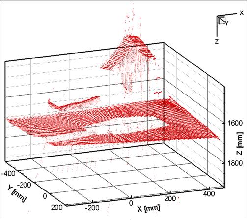
5 Fig. 5. Result of the proposed method. Obtained camera images (leftmost two columns), detected code bit images (3rd column), and a frame of 3D reconstruction result (rightmost) at 500 fps with 1,024 1,024 pixels camera images are shown. Fig. 6. Result of the conventional Gray code pattern projection method, at 500 fps with 1,024 1,024 pixels camera images. 3215


![AKNOWLEDGMENTS Part of this study is a joint work with Photron Limited supported by the Grant of the New Energy and Industrial Technology Development Organization (NEDO), Japan. REFERENES [1] J.](/docs-images/75/72152968/images/6-6.jpg "Batlle, E. Mouaddib, and J. Salvi. Recent progress in coded structured light as a technique to solve the correspondence problem: A survey. Pattern Recognition, 31(7):963 982, 1998.")
6 Fig. 7. Result of the proposed method, at 2,500 fps, pixels camera images. Fig. 8. images. Result of the proposed method, at 3,350 fps, camera code bit images by 5,000-fps projection and capturing with camera pixels, and a frame of reconstructed 3-D shape thus at 2,500 fps. Likewise, code bit images obtained by 6,700-fps projection and capturing with camera pixels and a frame of 3-D shape at 3,350-fps are shown in Fig. 8. This frame rate, 6,700 fps, is the maximum rate at which the projector and the camera could synchronize with each other using the TTL synchronization signal through the coaxial cable. The 3-D shape of the white rectangular solid was correctly reconstructed, but the human hand, of which the surface has lower reflectance, was hardly detected because of the shorter exposure times of the image sensor. V. ONLUSION A high-speed 3-D shape measurement system has been described. A novel technique called the temporally-coded multi-slit projection method enabled 3-D distance maps to be obtained every two frames, assuming that the system operates at a high frame rate. Implementing a high-speed projector based on an optics system of commercial projector and a DMD development kit, high frame rate binary image projection at several thousand fps has been achieved, being synchronized with an off-the-shelf high-speed camera. As a result, 3-D reconstruction at 500 fps with 1, 024 1, 024 camera pixels, or at 3,350 fps with camera pixels has been achieved. Future work includes hardware implementation of the image processing algorithm so that the system operates in real time, and to exploit the blank spaces between the slits in the projected patterns so that more dense 3-D distance maps can be obtained. AKNOWLEDGMENTS Part of this study is a joint work with Photron Limited supported by the Grant of the New Energy and Industrial Technology Development Organization (NEDO), Japan. REFERENES [1] J. Batlle, E. Mouaddib, and J. Salvi. Recent progress in coded structured light as a technique to solve the correspondence problem: A survey. Pattern Recognition, 31(7): , [2] Frank hen, Gordon M. Brown, and Mumin Song. Overview of three-dimensional shape measurement using optical methods. Optical Engineering, 39(1):10 22, [3] Shinichi Yoshimura, Toshinobu Sugiyama, Kazuya Yonemoto, and Kazuhiko Ueda. A 48kframe/s MOS image sensor for real-time 3-D sensing and motion detection. In Digest of Technical Papers of 2001 IEEE International Solid-State ircuits onference (ISS2001), pages 94 95, [4] Yusuke Oike, Makoto Ikeda, and Kunihiro Asada. A MOS image sensor for high-speed active range finding using column-parallel timedomain AD and position encoder. IEEE Transactions on Electron Devices, 50(1): , [5] M. Asada, H. Ichikawa, and S. Tsuji. Determining surface orientation by projecting a stripe pattern. IEEE Transactions on Pattern Analysis and Machine Intelligence, 10(5): , [6] Kazunori Umeda. A compact range image sensor suitable for robots. In 2004 IEEE International onference on Robotics and Automation (IRA2004), pages , [7] Dana Dudley, Walter Duncan, and John Slaughter. Emerging digital micromirror device (DMD) applications. Proceedings of SPIE, 4985, [8] Shingo Kagami, Masatsugu Shinmeimae, Takashi Komuro, Yoshihiro Watanabe, and Masatoshi Ishikawa. A pixel-parallel algorithm for detecting and tracking fast-moving modulated light signals. Journal of Robotics and Mechatronics, 17(4): , [9] Zhengyou Zhang. A flexible new technique for camera calibration. IEEE Transactions on Pattern Analysis and Machine Intelligence, 22(11): ,
A Coded Structured Light Projection Method for High-Frame-Rate 3D Image Acquisition
 A Coded Structured Light Projection Method for High-Frame-Rate D Image Acquisition 0 Idaku Ishii Hiroshima University Japan. Introduction Three-dimensional measurement technology has recently been used
Structured Light II. Guido Gerig CS 6320, Spring (thanks: slides Prof. S. Narasimhan, CMU, Marc Pollefeys, UNC)
") Structured Light II Guido Gerig CS 6320, Spring 2013 (thanks: slides Prof. S. Narasimhan, CMU, Marc Pollefeys, UNC) http://www.cs.cmu.edu/afs/cs/academic/class/15385- s06/lectures/ppts/lec-17.ppt Variant
Structured Light II Guido Gerig CS 6320, Spring 2013 (thanks: slides Prof. S. Narasimhan, CMU, Marc Pollefeys, UNC) http://www.cs.cmu.edu/afs/cs/academic/class/15385- s06/lectures/ppts/lec-17.ppt Variant
DEVELOPMENT OF REAL TIME 3-D MEASUREMENT SYSTEM USING INTENSITY RATIO METHOD
 DEVELOPMENT OF REAL TIME 3-D MEASUREMENT SYSTEM USING INTENSITY RATIO METHOD Takeo MIYASAKA and Kazuo ARAKI Graduate School of Computer and Cognitive Sciences, Chukyo University, Japan miyasaka@grad.sccs.chukto-u.ac.jp,
Structured Light. Tobias Nöll Thanks to Marc Pollefeys, David Nister and David Lowe
 Structured Light Tobias Nöll tobias.noell@dfki.de Thanks to Marc Pollefeys, David Nister and David Lowe Introduction Previous lecture: Dense reconstruction Dense matching of non-feature pixels Patch-based
A 100Hz Real-time Sensing System of Textured Range Images
 A 100Hz Real-time Sensing System of Textured Range Images Hidetoshi Ishiyama Course of Precision Engineering School of Science and Engineering Chuo University 1-13-27 Kasuga, Bunkyo-ku, Tokyo 112-8551,
3D Computer Vision. Structured Light I. Prof. Didier Stricker. Kaiserlautern University.
 3D Computer Vision Structured Light I Prof. Didier Stricker Kaiserlautern University http://ags.cs.uni-kl.de/ DFKI Deutsches Forschungszentrum für Künstliche Intelligenz http://av.dfki.de 1 Introduction
HIGH SPEED 3-D MEASUREMENT SYSTEM USING INCOHERENT LIGHT SOURCE FOR HUMAN PERFORMANCE ANALYSIS
 HIGH SPEED 3-D MEASUREMENT SYSTEM USING INCOHERENT LIGHT SOURCE FOR HUMAN PERFORMANCE ANALYSIS Takeo MIYASAKA, Kazuhiro KURODA, Makoto HIROSE and Kazuo ARAKI School of Computer and Cognitive Sciences,
Accurate and Dense Wide-Baseline Stereo Matching Using SW-POC
 Accurate and Dense Wide-Baseline Stereo Matching Using SW-POC Shuji Sakai, Koichi Ito, Takafumi Aoki Graduate School of Information Sciences, Tohoku University, Sendai, 980 8579, Japan Email: sakai@aoki.ecei.tohoku.ac.jp
Mirror Based Framework for Human Body Measurement
 362 Mirror Based Framework for Human Body Measurement 1 Takeshi Hashimoto, 2 Takayuki Suzuki, 3 András Rövid 1 Dept. of Electrical and Electronics Engineering, Shizuoka University 5-1, 3-chome Johoku,
Outdoor Scene Reconstruction from Multiple Image Sequences Captured by a Hand-held Video Camera
 Outdoor Scene Reconstruction from Multiple Image Sequences Captured by a Hand-held Video Camera Tomokazu Sato, Masayuki Kanbara and Naokazu Yokoya Graduate School of Information Science, Nara Institute
955-fps Real-time Shape Measurement of a Moving/Deforming Object using High-speed Vision for Numerous-point Analysis
 27 IEEE International Conference on Robotics and Automation Roma, Italy, 1-14 April 27 FrA2.4 955-fps Real-time Shape Measurement of a Moving/Deforming Object using High-speed Vision for Numerous-point
A three-step system calibration procedure with error compensation for 3D shape measurement
 January 10, 2010 / Vol. 8, No. 1 / CHINESE OPTICS LETTERS 33 A three-step system calibration procedure with error compensation for 3D shape measurement Haihua Cui ( ), Wenhe Liao ( ), Xiaosheng Cheng (
A FULL-COLOR SINGLE-CHIP-DLP PROJECTOR WITH AN EMBEDDED 2400-FPS HOMOGRAPHY WARPING ENGINE
 A FULL-COLOR SINGLE-CHIP-DLP PROJECTOR WITH AN EMBEDDED 2400-FPS HOMOGRAPHY WARPING ENGINE Shingo Kagami, Koichi Hashimoto Tohoku University 2018 SIGGRAPH. All Rights Reserved Photography & Recording Encouraged
A High Speed Face Measurement System
 A High Speed Face Measurement System Kazuhide HASEGAWA, Kazuyuki HATTORI and Yukio SATO Department of Electrical and Computer Engineering, Nagoya Institute of Technology Gokiso, Showa, Nagoya, Japan, 466-8555
High-resolution, real-time three-dimensional shape measurement
 Iowa State University From the SelectedWorks of Song Zhang December 13, 2006 High-resolution, real-time three-dimensional shape measurement Song Zhang, Harvard University Peisen S. Huang, State University
Depth. Common Classification Tasks. Example: AlexNet. Another Example: Inception. Another Example: Inception. Depth
 Common Classification Tasks Recognition of individual objects/faces Analyze object-specific features (e.g., key points) Train with images from different viewing angles Recognition of object classes Analyze
Handy Rangefinder for Active Robot Vision
 Handy Rangefinder for Active Robot Vision Kazuyuki Hattori Yukio Sato Department of Electrical and Computer Engineering Nagoya Institute of Technology Showa, Nagoya 466, Japan Abstract A compact and high-speed
What have we leaned so far?
 What have we leaned so far? Camera structure Eye structure Project 1: High Dynamic Range Imaging What have we learned so far? Image Filtering Image Warping Camera Projection Model Project 2: Panoramic
Miniaturized Camera Systems for Microfactories
 Miniaturized Camera Systems for Microfactories Timo Prusi, Petri Rokka, and Reijo Tuokko Tampere University of Technology, Department of Production Engineering, Korkeakoulunkatu 6, 33720 Tampere, Finland
Detecting motion by means of 2D and 3D information
 Detecting motion by means of 2D and 3D information Federico Tombari Stefano Mattoccia Luigi Di Stefano Fabio Tonelli Department of Electronics Computer Science and Systems (DEIS) Viale Risorgimento 2,
EASY PROJECTOR AND MONOCHROME CAMERA CALIBRATION METHOD USING PLANE BOARD WITH MULTIPLE ENCODED MARKERS
 EASY PROJECTOR AND MONOCHROME CAMERA CALIBRATION METHOD USING PLANE BOARD WITH MULTIPLE ENCODED MARKERS Tatsuya Hanayama 1 Shota Kiyota 1 Ryo Furukawa 3 Hiroshi Kawasaki 1 1 Faculty of Engineering, Kagoshima
High-speed Three-dimensional Mapping by Direct Estimation of a Small Motion Using Range Images
 MECATRONICS - REM 2016 June 15-17, 2016 High-speed Three-dimensional Mapping by Direct Estimation of a Small Motion Using Range Images Shinta Nozaki and Masashi Kimura School of Science and Engineering
Absolute Scale Structure from Motion Using a Refractive Plate
 Absolute Scale Structure from Motion Using a Refractive Plate Akira Shibata, Hiromitsu Fujii, Atsushi Yamashita and Hajime Asama Abstract Three-dimensional (3D) measurement methods are becoming more and
Range Imaging Through Triangulation. Range Imaging Through Triangulation. Range Imaging Through Triangulation. Range Imaging Through Triangulation
 Obviously, this is a very slow process and not suitable for dynamic scenes. To speed things up, we can use a laser that projects a vertical line of light onto the scene. This laser rotates around its vertical
Robust and Accurate One-shot 3D Reconstruction by 2C1P System with Wave Grid Pattern
 Robust and Accurate One-shot 3D Reconstruction by 2C1P System with Wave Grid Pattern Nozomu Kasuya Kagoshima University Kagoshima, Japan AIST Tsukuba, Japan nozomu.kasuya@aist.go.jp Ryusuke Sagawa AIST
Shape and deformation measurements by high-resolution fringe projection methods February 2018
 Shape and deformation measurements by high-resolution fringe projection methods February 2018 Outline Motivation System setup Principles of operation Calibration Applications Conclusions & Future work
3D Scanning. Qixing Huang Feb. 9 th Slide Credit: Yasutaka Furukawa
 3D Scanning Qixing Huang Feb. 9 th 2017 Slide Credit: Yasutaka Furukawa Geometry Reconstruction Pipeline This Lecture Depth Sensing ICP for Pair-wise Alignment Next Lecture Global Alignment Pairwise Multiple
Active Stereo Vision. COMP 4900D Winter 2012 Gerhard Roth
 Active Stereo Vision COMP 4900D Winter 2012 Gerhard Roth Why active sensors? Project our own texture using light (usually laser) This simplifies correspondence problem (much easier) Pluses Can handle different
Surround Structured Lighting for Full Object Scanning
 Surround Structured Lighting for Full Object Scanning Douglas Lanman, Daniel Crispell, and Gabriel Taubin Brown University, Dept. of Engineering August 21, 2007 1 Outline Introduction and Related Work
Gesture Recognition using Temporal Templates with disparity information
 8- MVA7 IAPR Conference on Machine Vision Applications, May 6-8, 7, Tokyo, JAPAN Gesture Recognition using Temporal Templates with disparity information Kazunori Onoguchi and Masaaki Sato Hirosaki University
Time-of-flight basics
 Contents 1. Introduction... 2 2. Glossary of Terms... 3 3. Recovering phase from cross-correlation... 4 4. Time-of-flight operating principle: the lock-in amplifier... 6 5. The time-of-flight sensor pixel...
3D Shape and Indirect Appearance By Structured Light Transport
 3D Shape and Indirect Appearance By Structured Light Transport CVPR 2014 - Best paper honorable mention Matthew O Toole, John Mather, Kiriakos N. Kutulakos Department of Computer Science University of
Measurement of 3D Foot Shape Deformation in Motion
 Measurement of 3D Foot Shape Deformation in Motion Makoto Kimura Masaaki Mochimaru Takeo Kanade Digital Human Research Center National Institute of Advanced Industrial Science and Technology, Japan The
An Innovative Three-dimensional Profilometer for Surface Profile Measurement Using Digital Fringe Projection and Phase Shifting
 An Innovative Three-dimensional Profilometer for Surface Profile Measurement Using Digital Fringe Projection and Phase Shifting Liang-Chia Chen 1, Shien-Han Tsai 1 and Kuang-Chao Fan 2 1 Institute of Automation
Flexible Calibration of a Portable Structured Light System through Surface Plane
 Vol. 34, No. 11 ACTA AUTOMATICA SINICA November, 2008 Flexible Calibration of a Portable Structured Light System through Surface Plane GAO Wei 1 WANG Liang 1 HU Zhan-Yi 1 Abstract For a portable structured
Parallel Extraction Architecture for Information of Numerous Particles in Real-Time Image Measurement
 Parallel Extraction Architecture for Information of Numerous Paper: Rb17-4-2346; May 19, 2005 Parallel Extraction Architecture for Information of Numerous Yoshihiro Watanabe, Takashi Komuro, Shingo Kagami,
Stereo and structured light
 Stereo and structured light http://graphics.cs.cmu.edu/courses/15-463 15-463, 15-663, 15-862 Computational Photography Fall 2018, Lecture 20 Course announcements Homework 5 is still ongoing. - Make sure
3D Sensing. 3D Shape from X. Perspective Geometry. Camera Model. Camera Calibration. General Stereo Triangulation.
 3D Sensing 3D Shape from X Perspective Geometry Camera Model Camera Calibration General Stereo Triangulation 3D Reconstruction 3D Shape from X shading silhouette texture stereo light striping motion mainly
Occlusion Detection of Real Objects using Contour Based Stereo Matching
 Occlusion Detection of Real Objects using Contour Based Stereo Matching Kenichi Hayashi, Hirokazu Kato, Shogo Nishida Graduate School of Engineering Science, Osaka University,1-3 Machikaneyama-cho, Toyonaka,
3D Sensing and Reconstruction Readings: Ch 12: , Ch 13: ,
 3D Sensing and Reconstruction Readings: Ch 12: 12.5-6, Ch 13: 13.1-3, 13.9.4 Perspective Geometry Camera Model Stereo Triangulation 3D Reconstruction by Space Carving 3D Shape from X means getting 3D coordinates
Dynamic 3-D surface profilometry using a novel color pattern encoded with a multiple triangular model
 Dynamic 3-D surface profilometry using a novel color pattern encoded with a multiple triangular model Liang-Chia Chen and Xuan-Loc Nguyen Graduate Institute of Automation Technology National Taipei University
DEVELOPMENT OF POSITION MEASUREMENT SYSTEM FOR CONSTRUCTION PILE USING LASER RANGE FINDER
 S17- DEVELOPMENT OF POSITION MEASUREMENT SYSTEM FOR CONSTRUCTION PILE USING LASER RANGE FINDER Fumihiro Inoue 1 *, Takeshi Sasaki, Xiangqi Huang 3, and Hideki Hashimoto 4 1 Technica Research Institute,
Surround Structured Lighting for Full Object Scanning
 Surround Structured Lighting for Full Object Scanning Douglas Lanman, Daniel Crispell, and Gabriel Taubin Department of Engineering, Brown University {dlanman,daniel crispell,taubin}@brown.edu Abstract
Stereo. 11/02/2012 CS129, Brown James Hays. Slides by Kristen Grauman
 Stereo 11/02/2012 CS129, Brown James Hays Slides by Kristen Grauman Multiple views Multi-view geometry, matching, invariant features, stereo vision Lowe Hartley and Zisserman Why multiple views? Structure
Three-Dimensional Sensors Lecture 2: Projected-Light Depth Cameras
 Three-Dimensional Sensors Lecture 2: Projected-Light Depth Cameras Radu Horaud INRIA Grenoble Rhone-Alpes, France Radu.Horaud@inria.fr http://perception.inrialpes.fr/ Outline The geometry of active stereo.
Creating a distortion characterisation dataset for visual band cameras using fiducial markers.
 Creating a distortion characterisation dataset for visual band cameras using fiducial markers. Robert Jermy Council for Scientific and Industrial Research Email: rjermy@csir.co.za Jason de Villiers Council
Phase error compensation for a 3-D shape measurement system based on the phase-shifting method
 46 6, 063601 June 2007 Phase error compensation for a 3-D shape measurement system based on the phase-shifting method Song Zhang, MEMBER SPIE Harvard University Department of Mathematics Cambridge, Massachusetts
3D Terrain Sensing System using Laser Range Finder with Arm-Type Movable Unit
 3D Terrain Sensing System using Laser Range Finder with Arm-Type Movable Unit 9 Toyomi Fujita and Yuya Kondo Tohoku Institute of Technology Japan 1. Introduction A 3D configuration and terrain sensing
Dense 3-D Reconstruction of an Outdoor Scene by Hundreds-baseline Stereo Using a Hand-held Video Camera
 Dense 3-D Reconstruction of an Outdoor Scene by Hundreds-baseline Stereo Using a Hand-held Video Camera Tomokazu Satoy, Masayuki Kanbaray, Naokazu Yokoyay and Haruo Takemuraz ygraduate School of Information
Dynamic three-dimensional sensing for specular surface with monoscopic fringe reflectometry
 Dynamic three-dimensional sensing for specular surface with monoscopic fringe reflectometry Lei Huang,* Chi Seng Ng, and Anand Krishna Asundi School of Mechanical and Aerospace Engineering, Nanyang Technological
Project Title: Welding Machine Monitoring System Phase II. Name of PI: Prof. Kenneth K.M. LAM (EIE) Progress / Achievement: (with photos, if any)
 Progress / Achievement: (with photos, if any)") Address: Hong Kong Polytechnic University, Phase 8, Hung Hom, Kowloon, Hong Kong. Telephone: (852) 3400 8441 Email: cnerc.steel@polyu.edu.hk Website: https://www.polyu.edu.hk/cnerc-steel/ Project Title:
Address: Hong Kong Polytechnic University, Phase 8, Hung Hom, Kowloon, Hong Kong. Telephone: (852) 3400 8441 Email: cnerc.steel@polyu.edu.hk Website: https://www.polyu.edu.hk/cnerc-steel/ Project Title:
Dynamic Reconstruction for Coded Aperture Imaging Draft Unpublished work please do not cite or distribute.
 Dynamic Reconstruction for Coded Aperture Imaging Draft 1.0.1 Berthold K.P. Horn 2007 September 30. Unpublished work please do not cite or distribute. The dynamic reconstruction technique makes it possible
From infinity To infinity Object Projected spot Z: dinstance Lens center b: baseline length Image plane k f: focal length k CCD camera Origin (Project
 Construction of a coaxial textured range image sensing system Yuki Uchida, Shinta Nozaki, Kenji Terabayashi and Kazunori Umeda Course of Precision Engineering, School of Science and Engineering, Chuo University,
A 3-D Scanner Capturing Range and Color for the Robotics Applications
 J.Haverinen & J.Röning, A 3-D Scanner Capturing Range and Color for the Robotics Applications, 24th Workshop of the AAPR - Applications of 3D-Imaging and Graph-based Modeling, May 25-26, Villach, Carinthia,
Multimedia Technology CHAPTER 4. Video and Animation
 CHAPTER 4 Video and Animation - Both video and animation give us a sense of motion. They exploit some properties of human eye s ability of viewing pictures. - Motion video is the element of multimedia
International Journal of Advance Engineering and Research Development
 Scientific Journal of Impact Factor (SJIF): 4.14 International Journal of Advance Engineering and Research Development Volume 3, Issue 3, March -2016 e-issn (O): 2348-4470 p-issn (P): 2348-6406 Research
Integration of Multiple-baseline Color Stereo Vision with Focus and Defocus Analysis for 3D Shape Measurement
 Integration of Multiple-baseline Color Stereo Vision with Focus and Defocus Analysis for 3D Shape Measurement Ta Yuan and Murali Subbarao tyuan@sbee.sunysb.edu and murali@sbee.sunysb.edu Department of
Construction Progress Management and Interior Work Analysis Using Kinect 3D Image Sensors
 33 rd International Symposium on Automation and Robotics in Construction (ISARC 2016) Construction Progress Management and Interior Work Analysis Using Kinect 3D Image Sensors Kosei Ishida 1 1 School of
Digital Halftoning Algorithm Based o Space-Filling Curve
 JAIST Reposi https://dspace.j Title Digital Halftoning Algorithm Based o Space-Filling Curve Author(s)ASANO, Tetsuo Citation IEICE TRANSACTIONS on Fundamentals o Electronics, Communications and Comp Sciences,
Compact and Low Cost System for the Measurement of Accurate 3D Shape and Normal
 Compact and Low Cost System for the Measurement of Accurate 3D Shape and Normal Ryusuke Homma, Takao Makino, Koichi Takase, Norimichi Tsumura, Toshiya Nakaguchi and Yoichi Miyake Chiba University, Japan
A Comparison between Active and Passive 3D Vision Sensors: BumblebeeXB3 and Microsoft Kinect
 A Comparison between Active and Passive 3D Vision Sensors: BumblebeeXB3 and Microsoft Kinect Diana Beltran and Luis Basañez Technical University of Catalonia, Barcelona, Spain {diana.beltran,luis.basanez}@upc.edu
A Simple Interface for Mobile Robot Equipped with Single Camera using Motion Stereo Vision
 A Simple Interface for Mobile Robot Equipped with Single Camera using Motion Stereo Vision Stephen Karungaru, Atsushi Ishitani, Takuya Shiraishi, and Minoru Fukumi Abstract Recently, robot technology has
Task selection for control of active vision systems
 The 29 IEEE/RSJ International Conference on Intelligent Robots and Systems October -5, 29 St. Louis, USA Task selection for control of active vision systems Yasushi Iwatani Abstract This paper discusses
STEREO BY TWO-LEVEL DYNAMIC PROGRAMMING
 STEREO BY TWO-LEVEL DYNAMIC PROGRAMMING Yuichi Ohta Institute of Information Sciences and Electronics University of Tsukuba IBARAKI, 305, JAPAN Takeo Kanade Computer Science Department Carnegie-Mellon
Temporally-Consistent Phase Unwrapping for a Stereo-Assisted Structured Light System
 Temporally-Consistent Phase Unwrapping for a Stereo-Assisted Structured Light System Ricardo R. Garcia and Avideh Zakhor Department of Electrical Engineering and Computer Science University of California,
Infrared Camera Calibration in the 3D Temperature Field Reconstruction
 , pp.27-34 http://dx.doi.org/10.14257/ijmue.2016.11.6.03 Infrared Camera Calibration in the 3D Temperature Field Reconstruction Sun Xiaoming, Wu Haibin, Wang Wei, Liubo and Cui Guoguang The higher Educational
3D Environment Measurement Using Binocular Stereo and Motion Stereo by Mobile Robot with Omnidirectional Stereo Camera
 3D Environment Measurement Using Binocular Stereo and Motion Stereo by Mobile Robot with Omnidirectional Stereo Camera Shinichi GOTO Department of Mechanical Engineering Shizuoka University 3-5-1 Johoku,
Projection Center Calibration for a Co-located Projector Camera System
 Projection Center Calibration for a Co-located Camera System Toshiyuki Amano Department of Computer and Communication Science Faculty of Systems Engineering, Wakayama University Sakaedani 930, Wakayama,
IEEE JOURNAL OF SELECTED TOPICS IN SIGNAL PROCESSING, VOL. 6, NO. 5, SEPTEMBER
 IEEE JOURNAL OF SELECTED TOPICS IN SIGNAL PROCESSING, VOL. 6, NO. 5, SEPTEMBER 2012 411 Consistent Stereo-Assisted Absolute Phase Unwrapping Methods for Structured Light Systems Ricardo R. Garcia, Student
Supplementary materials of Multispectral imaging using a single bucket detector
 Supplementary materials of Multispectral imaging using a single bucket detector Liheng Bian 1, Jinli Suo 1,, Guohai Situ 2, Ziwei Li 1, Jingtao Fan 1, Feng Chen 1 and Qionghai Dai 1 1 Department of Automation,
Depth Camera for Mobile Devices
 Depth Camera for Mobile Devices Instructor - Simon Lucey 16-423 - Designing Computer Vision Apps Today Stereo Cameras Structured Light Cameras Time of Flight (ToF) Camera Inferring 3D Points Given we have
Projector Calibration for Pattern Projection Systems
 Projector Calibration for Pattern Projection Systems I. Din *1, H. Anwar 2, I. Syed 1, H. Zafar 3, L. Hasan 3 1 Department of Electronics Engineering, Incheon National University, Incheon, South Korea.
StereoScan: Dense 3D Reconstruction in Real-time
 STANFORD UNIVERSITY, COMPUTER SCIENCE, STANFORD CS231A SPRING 2016 StereoScan: Dense 3D Reconstruction in Real-time Peirong Ji, pji@stanford.edu June 7, 2016 1 INTRODUCTION In this project, I am trying
Minimizing Noise and Bias in 3D DIC. Correlated Solutions, Inc.
 Minimizing Noise and Bias in 3D DIC Correlated Solutions, Inc. Overview Overview of Noise and Bias Digital Image Correlation Background/Tracking Function Minimizing Noise Focus Contrast/Lighting Glare
Change detection using joint intensity histogram
 Change detection using joint intensity histogram Yasuyo Kita National Institute of Advanced Industrial Science and Technology (AIST) Information Technology Research Institute AIST Tsukuba Central 2, 1-1-1
3D Modeling of Objects Using Laser Scanning
 1 3D Modeling of Objects Using Laser Scanning D. Jaya Deepu, LPU University, Punjab, India Email: Jaideepudadi@gmail.com Abstract: In the last few decades, constructing accurate three-dimensional models
Measurement of Pedestrian Groups Using Subtraction Stereo
 Measurement of Pedestrian Groups Using Subtraction Stereo Kenji Terabayashi, Yuki Hashimoto, and Kazunori Umeda Chuo University / CREST, JST, 1-13-27 Kasuga, Bunkyo-ku, Tokyo 112-8551, Japan terabayashi@mech.chuo-u.ac.jp
ENGN 2911 I: 3D Photography and Geometry Processing Assignment 2: Structured Light for 3D Scanning
 ENGN 2911 I: 3D Photography and Geometry Processing Assignment 2: Structured Light for 3D Scanning Instructor: Gabriel Taubin Assignment written by: Douglas Lanman 26 February 2009 Figure 1: Structured
Overview of Active Vision Techniques
 SIGGRAPH 99 Course on 3D Photography Overview of Active Vision Techniques Brian Curless University of Washington Overview Introduction Active vision techniques Imaging radar Triangulation Moire Active
Deduction and Logic Implementation of the Fractal Scan Algorithm
 Deduction and Logic Implementation of the Fractal Scan Algorithm Zhangjin Chen, Feng Ran, Zheming Jin Microelectronic R&D center, Shanghai University Shanghai, China and Meihua Xu School of Mechatronical
Random spatial sampling and majority voting based image thresholding
 1 Random spatial sampling and majority voting based image thresholding Yi Hong Y. Hong is with the City University of Hong Kong. yihong@cityu.edu.hk November 1, 7 2 Abstract This paper presents a novel
Omni-directional Multi-baseline Stereo without Similarity Measures
 Omni-directional Multi-baseline Stereo without Similarity Measures Tomokazu Sato and Naokazu Yokoya Graduate School of Information Science, Nara Institute of Science and Technology 8916-5 Takayama, Ikoma,
CHAPTER 2: THREE DIMENSIONAL TOPOGRAPHICAL MAPPING SYSTEM. Target Object
 CHAPTER 2: THREE DIMENSIONAL TOPOGRAPHICAL MAPPING SYSTEM 2.1 Theory and Construction Target Object Laser Projector CCD Camera Host Computer / Image Processor Figure 2.1 Block Diagram of 3D Areal Mapper
Augmenting Reality with Projected Interactive Displays
 Augmenting Reality with Projected Interactive Displays Claudio Pinhanez IBM T.J. Watson Research Center, P.O. Box 218 Yorktown Heights, N.Y. 10598, USA Abstract. This paper examines a steerable projection
Fast 3-D Shape Measurement Using Blink-Dot Projection
 203 IEEE/RSJ International Conference on Intelligent Robots and Systems (IROS) November 3-7, 203. Tokyo, Japan Fast 3-D Shape Measurement Using Blink-Dot Projection Jun Chen, Qingyi Gu, Hao Gao, Tadayoshi
MOTION STEREO DOUBLE MATCHING RESTRICTION IN 3D MOVEMENT ANALYSIS
 MOTION STEREO DOUBLE MATCHING RESTRICTION IN 3D MOVEMENT ANALYSIS ZHANG Chun-sen Dept of Survey, Xi an University of Science and Technology, No.58 Yantazhonglu, Xi an 710054,China -zhchunsen@yahoo.com.cn
CS 787: Assignment 4, Stereo Vision: Block Matching and Dynamic Programming Due: 12:00noon, Fri. Mar. 30, 2007.
 CS 787: Assignment 4, Stereo Vision: Block Matching and Dynamic Programming Due: 12:00noon, Fri. Mar. 30, 2007. In this assignment you will implement and test some simple stereo algorithms discussed in
Lumaxis, Sunset Hills Rd., Ste. 106, Reston, VA 20190
 White Paper High Performance Projection Engines for 3D Metrology Systems www.lumaxis.net Lumaxis, 11495 Sunset Hills Rd., Ste. 106, Reston, VA 20190 Introduction 3D optical metrology using structured light
Development of a video-rate range finder using dynamic threshold method for characteristic point detection
 Engineering Industrial & Management Engineering fields Year 1999 Development of a video-rate range finder using dynamic threshold method for characteristic point detection Yutaka Tanaka Nobuo Takeda Akio
ENGN D Photography / Spring 2018 / SYLLABUS
 ENGN 2502 3D Photography / Spring 2018 / SYLLABUS Description of the proposed course Over the last decade digital photography has entered the mainstream with inexpensive, miniaturized cameras routinely
Auto-focusing Technique in a Projector-Camera System
 2008 10th Intl. Conf. on Control, Automation, Robotics and Vision Hanoi, Vietnam, 17 20 December 2008 Auto-focusing Technique in a Projector-Camera System Lam Bui Quang, Daesik Kim and Sukhan Lee School
Sensing Deforming and Moving Objects with Commercial Off the Shelf Hardware
 Sensing Deforming and Moving Objects with Commercial Off the Shelf Hardware This work supported by: Philip Fong Florian Buron Stanford University Motivational Applications Human tissue modeling for surgical
Advanced Stamping Manufacturing Engineering, Auburn Hills, MI
 RECENT DEVELOPMENT FOR SURFACE DISTORTION MEASUREMENT L.X. Yang 1, C.Q. Du 2 and F. L. Cheng 2 1 Dep. of Mechanical Engineering, Oakland University, Rochester, MI 2 DaimlerChrysler Corporation, Advanced
LIGHT STRIPE PROJECTION-BASED PEDESTRIAN DETECTION DURING AUTOMATIC PARKING OPERATION
 F2008-08-099 LIGHT STRIPE PROJECTION-BASED PEDESTRIAN DETECTION DURING AUTOMATIC PARKING OPERATION 1 Jung, Ho Gi*, 1 Kim, Dong Suk, 1 Kang, Hyoung Jin, 2 Kim, Jaihie 1 MANDO Corporation, Republic of Korea,
Camera Calibration. Schedule. Jesus J Caban. Note: You have until next Monday to let me know. ! Today:! Camera calibration
 Camera Calibration Jesus J Caban Schedule! Today:! Camera calibration! Wednesday:! Lecture: Motion & Optical Flow! Monday:! Lecture: Medical Imaging! Final presentations:! Nov 29 th : W. Griffin! Dec 1
Multi-View Stereo for Community Photo Collections Michael Goesele, et al, ICCV Venus de Milo
 Vision Sensing Multi-View Stereo for Community Photo Collections Michael Goesele, et al, ICCV 2007 Venus de Milo The Digital Michelangelo Project, Stanford How to sense 3D very accurately? How to sense
Optical Flow-Based Person Tracking by Multiple Cameras
 Proc. IEEE Int. Conf. on Multisensor Fusion and Integration in Intelligent Systems, Baden-Baden, Germany, Aug. 2001. Optical Flow-Based Person Tracking by Multiple Cameras Hideki Tsutsui, Jun Miura, and
Color Segmentation Based Depth Adjustment for 3D Model Reconstruction from a Single Input Image
 Color Segmentation Based Depth Adjustment for 3D Model Reconstruction from a Single Input Image Vicky Sintunata and Terumasa Aoki Abstract In order to create a good 3D model reconstruction from an image,
Reprint. from the Journal. of the SID
 A 23-in. full-panel-resolution autostereoscopic LCD with a novel directional backlight system Akinori Hayashi (SID Member) Tomohiro Kometani Akira Sakai (SID Member) Hiroshi Ito Abstract An autostereoscopic
Pattern Feature Detection for Camera Calibration Using Circular Sample
 Pattern Feature Detection for Camera Calibration Using Circular Sample Dong-Won Shin and Yo-Sung Ho (&) Gwangju Institute of Science and Technology (GIST), 13 Cheomdan-gwagiro, Buk-gu, Gwangju 500-71,