New Frontiers in CAE Interoperability. Andy Chinn ITI TranscenData
|
|
|
- Amberlynn Greer
- 6 years ago
- Views:
Transcription

1 New Frontiers in CAE Interoperability Andy Chinn ITI TranscenData
2 Introduction Data Exchange Integrity Issue of Meshability Geometry Reasoning Geometry Reasoning Applications Conclusions
3 ITI TranscenData Europe Overview CAE and CAD background Meshing pioneer and research in the 1960 s FEGS Ltd formed in 1978 Original focus on CAE pre- and post-processing 1 st generation - FEMGEN & FEMVIEW 2 nd generation - FAM Field Analysis Modeller FAM 4 Re-focussed on key role of CAE geometry in rd generation - CADfix European subsidiary of ITI TranscenData in 1998 Leading provider of CAD/CAM/CAE/PDM interoperability solutions Focus on the critical role of CAD geometry in engineering processes, particularly CAD to CAE and process automation
4 Data Exchange Integrity Requirements Valid solids and well connected shells Seamless interface with little or no rework requirement Frequently not as straightforward as it should be! Different tolerances between systems System dependant geometrical and topological representations Poor implementations or adoption of standards e.g. IGES and STEP Different levels of complexity supported across diverse systems Data exchange is not the core business of a CAD or CAE system vendor and is often seen as an unwanted distraction


5 Data Exchange Integrity Example
6 Data Exchange Integrity Improvements There have been significant advances and improvements CAD system evolution, translator development and standards IGES translators fixed, STEP matured, translator support improved Kernels, e.g. Parasolid, more widely used as basis for CAD/CAE applications New native CAD translators Specialist and CAD data exchange and repair tools now available CAD and CAE System Integration Corporate CAD/CAE acquisitions for more integration and less translation Rationalisation of CAD systems and underlying geometry kernels Communication, awareness, modelling procedures and training


7 Meshability High integrity basic data exchange is not enough for CAE Need to consider the Meshability of the model Underlying geometrical definitions appropriate for meshing Appropriate level of detail required by the CAE process Simplest representation to reduce Degrees of Freedom and run time whilst maintaining design intent


8 Meshability Example - Invalid Surfaces Casting analysis across different systems Pro/E to CATIA CATIA to STL STL to MAGMA Solid contained over 300 badly defined or invalid surfaces!


9 Meshability Example - Design Features Part imports as solid and meshes automatically 57,100 elements 112,976 nodes Unwanted design features result in complex and dense mesh Simplified Model 15,360 elements 30,823 nodes


10 Meshability Example - CAD Artefacts Part imports as solid and meshes automatically 107,344 elements 160,001 nodes Unwanted small features result in complex and dense mesh Simplified Model Short edge removal, small face collapse, Face joining 22,113 elements 35,057 nodes
11 Meshability Improvements Short edges and small faces are less of an issue today But not for everyone Software Some meshers now suppress and mesh over topology constraints Data exchange tools developed to offer defeaturing capabilities Hardware Faster machines cope with larger problems But still DoF and time limitations (e.g. optimisation runs) System Integration Single geometry PLM model allows for CAD feature suppression But don t always have native CAD access with history tree
12 Advanced Applications and Automation Still more advanced geometry idealisation issues De-featuring - difference between intended and unwanted features Dimensional reduction - thin model to shell elements Domain partitioning - hex meshing or CFD block gridding Different considerations for different disciplines FEA stress raisers, CFD vortex inducers, CEM spark gaps Still mostly interactive and dependent on judgement e.g. When is a rib not a rib? Idealisation for CAE is difficult to automate and whilst the CAD BREP serves it s intended purpose well, it doesn t provide what is required to make intelligent CAE decisions


 of the CAD model GR technology is")

13 Geometry Reasoning A more intelligent use of a CAD model beyond what a BREP offers is needed TranscenData has developed an application to walk around the inside of an object, deducing properties Proximity Aspect ratio Thinnest Thickest Geometric Reasoning (GR) of the CAD model GR technology is key to future CAD-CAE process automation and will lead to major breakthroughs in engineering analysis applications


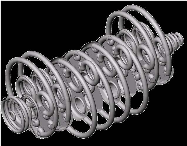
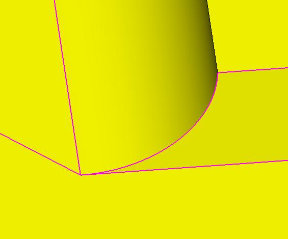
14 Medial Object and Geometry Reasoning Geometric Reasoning based on the Medial Object (MO) - or Medial Axis Transform MO is formed by rolling a maximal diameter disc inside a face, or a sphere inside a volume Path of the center of the disc or sphere describes the MO geometry MO populated with attributes Radius function = distance to boundary Parent geometry = geometrical entities that the medial object relates to Accurate, robust and complete 3D MO generation is not easy! Several years research and development at TranscenData and Queens University


15 3D Medial Object Examples Automatically generated MO of solid parts Non-manifold NURBS MO geometry


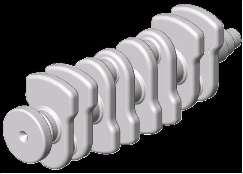
16 3D Medial Object Attributes MO is rich with 3D attributes and properties Radius function Parent geometry MO geometry and attributes available as the basis to build advanced CAD-CAE applications Contours of medial radius shown on MO geometry and parent geometry
17 MO Demonstration Medial Object generation and interrogation


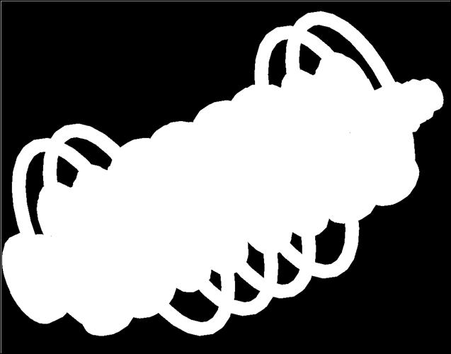
18 Many GR applications Feature recognition Spatial partitioning Dimensional reduction Mid-surfacing Shelling Geometry Reasoning Applications Manufacturability GR is key to future CAD-CAE integration


19 Proximity Tools for Meshing Challenge to automatically determine optimum element sizes GR offers a means to rapidly extract reliable proximity information Automatic edge-to-edge proximity within a face available today Promise of full 3D proximity inside and outside an object 2D MO, radius function and local mesh of gasket face


20 Robust Offsetting and Shelling GR used for robust and accurate offset and shelling Boundary layers Shrinkage Domain partitioning


21 Automatic Defeaturing Recognition of features defined by proximity and relative size Constrictions, pockets, through holes, voids Necks, slots, steps, tangencies, spikes, shoulders Protrusions, pockets Identifying features for simplification or automatic removal


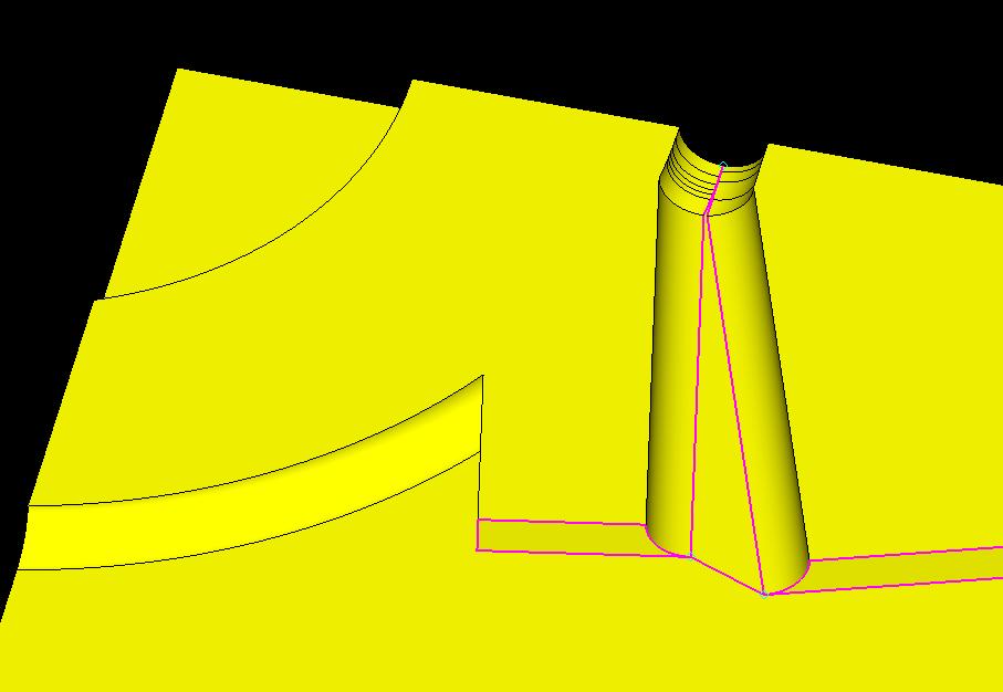
22 Automatic 2D Defeaturing 2D MO used to identify and fix potential problem areas for meshing Narrow regions Tangential conditions Sharp edge angles User control of process Threshold distance Merge position Truncate or merge to fix Intelligent automation


23 Automatic Defeaturing - Sharp Angle Fixer


24 Automatic 3D Defeaturing 3D MO offers the promise of intelligent 3D model defeaturing for analysis 1. CAD Part 2. Generate Medial Object 3. Identify major/ minor MO feature faces 4. Relationship back to parent CAD faces 5. Remove unwanted features


25 Spatial Partitioning / Subdivision GR using MO enables a geometry model to be traversed systematically in order to subdivide it into regions with limited complexity Automatic 2D subdivision for mapped meshing is an established method Potential for 3D GR subdivision 3D subdivision for Hex dominant meshing 3D subdivision for CFD body-fitted grids Thin-thick subdivision for mixed dimensional modeling


26 Mid Surface Extraction Automatic extraction of well connected and accurate mid surface models MO is close to a full mid surface - but not quite! Need to deal with intersections, edge conditions, thick regions Configurable GR application for accurate mid surfacing 100% theoretical sharp intersections Influence of features on shape of mid surface (effect of fillets etc) Not yet a full mid surface - but close! Major MO faces shown in red


27 Thin-Thick Subdivision Subdivision of a model into thin and thick regions Exploit theory of bending Mixed dimensional solid and shell mesh and analysis Significant degree of freedom reduction Potential for massive time savings for iterative optimisation analysis What is needed to make this a realistic application? Automatic process to derive a well connected, mixed dimensional model Facility to manage solid-shell interface in downstream analysis Potential for an analysis time reduction by a factor of
 Automatic derivation of 3D")
28 VIVACE Project Thin-Thick subdivision and mixed dimensional modelling was developed as part of the European VIVACE project involving aerospace companies, their suppliers, Universities and research institutes and software vendors A mixed-dimensional modelling methodology was researched and shown as a viable option for aero engine dynamics studies (Queens University) Automatic derivation of 3D thin-thick model from CAD (TranscenData) Demonstrated in a commercial analysis environment (Aero engine OEM) Tet mesh and analysis of engine component compared to that for a dimensionally reduced model Degrees of Freedom reduced from 9e6 to 7e5 Analysis time reduced by two orders of magnitude Acceptable error and mass deviation


29 Implementation of Thin-Thick Subdivision Implementation based on MO/GR with user controls for: Aspect ratio Setback factor Stay-thick tags Leave thick border on sheets Split into thin/thick solids Stress concentrations at shell edges (solution is 3D) Need to extend solids into shell region to capture stress concentrations Set Back Factor ensures valid stress pattern for shell elements and the application of bending theory Images courtesy of Queens University and VIVACE project

30 Original CAD part Thin-Thick Subdivision Example Full Tetrahedral mesh of section with too many DOF for iterative optimisation analysis Model courtesy of VIVACE project


31 Thin-Thick Subdivision Example Utilise MO geometry and attributes for Geometry Reasoning and automatically derive Thin-Thick subdivided model Thick solids Thin Shells Model courtesy of VIVACE project Subdivided model

32 Thin-Thick Subdivision Example Export subdivided model with required shell-solid connectivity attributes to CAE system for meshing and analysis Shell-solid connectivity achieved downstream with MPCs Auto generation possible using connectivity and mappings exported with mixed shell-solid geometry model Mixed tet and shell mesh with significant DoF saving Model courtesy of VIVACE project
33 Thin-Thick Subdivision Demonstration GR application to automatically subdivide a CAD model into thin and thick regions


")


34 Wedge and Hex Dominant Meshing Extrude surface mesh using MO proximity data (thickness map) Model courtesy of VIVACE project Tri mesh extruded for mixed tet and wedge mesh Quad mesh extruded for mixed tet and hex mesh Subdivision for hex dominant meshing Hex where possible but some regions left for tet meshing

35 Geometry is fundamental to future CAD-CAE processes Data exchange integrity and meshability has improved Demanding requirements for specialist CAE applications and process automation Automatic and intelligent defeaturing Automatic subdivision - 2D, Thin-Thick, Hex dominant, Fully Hex Mid surface extraction Shelling Conclusions Geometric Reasoning technology is unique with significant potential GR is key to future CAD-CAE integration and automation
36 CADfix Developments for CAE Exchange Integrity Meshability Process Automation CAD to CAE Issues Geometry Repair Geometry Transform Geometry Reasoning
37 New Frontiers in CAE Interoperability Thank you Any questions? Andy Chinn ITI TranscenData
Advanced geometry tools for CEM
 Advanced geometry tools for CEM Introduction Modern aircraft designs are extremely complex CAD models. For example, a BAE Systems aircraft assembly consists of over 30,000 individual components. Since
Shrinkwrap developments for computational electromagnetics in ICE NITe
 Shrinkwrap developments for computational electromagnetics in ICE NITe Preparing CAD models for electromagnetic analysis remains a complex, time consuming process. Typically, the CAD model will contain
VII. 3-D Meshing. 7.1 When to Use 3-D Elements
 VII 3-D Meshing This chapter includes material from the book Practical Finite Element Analysis. It also has been reviewed and has additional material added by Matthias Goelke. 7.1 When to Use 3-D Elements
Introduction to ANSYS ICEM CFD
 Lecture 4 Volume Meshing 14. 0 Release Introduction to ANSYS ICEM CFD 1 2011 ANSYS, Inc. March 21, 2012 Introduction to Volume Meshing To automatically create 3D elements to fill volumetric domain Generally
Using mesh-geometry relationships to transfer analysis models between CAE tools
 Using mesh-geometry relationships to transfer analysis models between CAE tools Tierney, C., Nolan, D., Robinson, T., & Armstrong, C. (2015). Using mesh-geometry relationships to transfer analysis models
Topology Optimization for Designers
 TM Topology Optimization for Designers Siemens AG 2016 Realize innovation. Topology Optimization for Designers Product Features Uses a different approach than traditional Topology Optimization solutions.
Best Practices: Volume Meshing Kynan Maley
 Best Practices: Volume Meshing Kynan Maley Volume Meshing Volume meshing is the basic tool that allows the creation of the space discretization needed to solve most of the CAE equations for: CFD Stress
NX Advanced FEM. fact sheet
 Advanced FEM fact sheet www.ugs.com Summary Advanced FEM is a comprehensive multi-cad finite element modeling and results visualization product that is designed to meet the needs of experienced CAE analysts.
Automatic & Robust Meshing in Fluids 2011 ANSYS Regional Conferences
 Automatic & Robust Meshing in Fluids 2011 ANSYS Regional Conferences 1 This is just a taste Note that full 14.0 update webinars of an hour per product will be scheduled closer to the release This presentation
Simulation Model Creation and Assembly Essentials. R2014x
 Simulation Model Creation and Assembly Essentials R2014x About this Course Course objectives Upon completion of this course you will be able to: Clean and repair native and imported geometry. Use advanced
10Femap10Femap10Fem. DeepDiveDeepDiveD
 ap DeepDive 10Femap10Fe DiveDeepDiveDeep map10femap10femap edeepdivedeepdivedeepdive p10femap10femap10femap10 pdivedeepdivedeepdivedeepd 10Femap10Femap10Fem DeepDiveDeepDiveD map10femap1 DiveDeep 10 F
Obtaining Meshable Surfaces
 Chapter 2 Obtaining Meshable Surfaces Exercise 2a: Importing and Repairing CAD Geometry Overview of Exercise Strategy: Import CAD geometry and organize your model using the Assembly Hierarchy. Evaluate
Feature and Topology Detection
 Feature and Topology Detection Greater possibilities with Capvidia extension and PARTsolutions Cadenas Industry Forum February 5th, 2015 Thomas Tillmann Capvidia GmbH Agenda Company Overview Application
Geometry Definition in the ADINA User Interface (AUI) Daniel Jose Payen, Ph.D. March 7, 2016
 Daniel Jose Payen, Ph.D. March 7, 2016") Geometry Definition in the ADINA User Interface (AUI) Daniel Jose Payen, Ph.D. March 7, 2016 ADINA R&D, Inc., 2016 1 Topics Presented ADINA에서쓰이는 Geometry 종류 Simple (AUI) geometry ADINA-M geometry ADINA-M
Geometry Definition in the ADINA User Interface (AUI) Daniel Jose Payen, Ph.D. March 7, 2016 ADINA R&D, Inc., 2016 1 Topics Presented ADINA에서쓰이는 Geometry 종류 Simple (AUI) geometry ADINA-M geometry ADINA-M
Femap automatic meshing simplifies virtual testing of even the toughest assignments
 Femap automatic meshing simplifies virtual testing of even the toughest assignments fact sheet Siemens PLM Software www.siemens.com/plm/femap Summary Femap version 10 software is the latest release of
Automatic & Robust Meshing in Fluids 2011 ANSYS Regional Conferences
 Automatic & Robust Meshing in Fluids 2011 ANSYS Regional Conferences 1 Automatic & Robust Meshing Assembly Meshing Assembly Meshing enables dramatically reduced time to mesh for typical CAD models by eliminating
CAD INTEROPERABILITY SOFTWARE SUITE
 CAD INTEROPERABILITY SOFTWARE SUITE 1 3D_Evolution Conversion Engine is today s leading MCAD collaboration suite. Designed for a seamless, integrated process, it is the ideal enhancement for your PLM environment.
NX Advanced FEM. Benefits
 Advanced FEM fact sheet Siemens PLM Software www.siemens.com/plm Summary Advanced FEM software is a comprehensive multi-cad finite element modeling and results visualization product that is designed to
CATIA V5R21 - FACT SHEET
 CATIA V5R21 - FACT SHEET Introduction What s New at a Glance Overview Detailed Description INTRODUCTION CATIA V5 is the leading solution for product success. It addresses all manufacturing organizations;
PARAMETRIC MODELING FOR MECHANICAL COMPONENTS 1
 PARAMETRIC MODELING FOR MECHANICAL COMPONENTS 1 Wawre S.S. Abstract: parametric modeling is a technique to generalize specific solid model. This generalization of the solid model is used to automate modeling
CADfix 10 SP2 Data Exchange Fix Change Notes
 CADfix 10 SP2 Data Exchange Fix Change Notes Change Notes for CADfix 10 SP2 as a brief summary of each fix arranged under their respective Problem report number(s): 7961 Parasolid imported Toroid Face
Abaqus/CAE: Geometry Import and Meshing
 Abaqus/CAE: Geometry Import and Meshing Day 1 Overview of Abaqus/CAE Lecture 1 Demonstration 1 Demonstration 2 Workshop 1 Workshop 2 Workshop 3 Geometry Import and Repair Geometry Import and Repair: Lens
Geometry Clean-up in. Numerical Simulations
 Geometry Clean-up in Numerical Simulations Scope of the this Presentation The guidelines are very generic in nature and has been explained with examples. However, the users may need to check their software
ANSYS 14.0 Geometry and Meshing Update Steve Varnam ANSYS UK Ltd.
 ANSYS 14.0 Geometry and Meshing Update Steve Varnam ANSYS UK Ltd. 1 ANSYS Workbench Platform The most comprehensive platform for Multiphysics Simulations ANSYS Workbench Framework ANSYS DesignXplorer ANSYS
Automated CFD blade design within a CAD system
 Automated CFD blade design within a CAD system Petter Andersson, Volvo Aero Corporation, Sweden Malin Ludvigson, Volvo Aero Corporation, Sweden Ola Isaksson, Volvo Aero Corporation, Sweden Summary: The
Convergent Modeling and Reverse Engineering
 Convergent Modeling and Reverse Engineering 25 October 2017 Realize innovation. Tod Parrella NX Design Product Management Product Engineering Solutions tod.parrella@siemens.com Realize innovation. Siemens
Abaqus/CAE: Geometry Import and Meshing. About this Course
 Abaqus/CAE: Geometry Import and Meshing R 6.12 About this Course Course objectives Upon completion of this course you will be able to: Import, edit, and repair CAD geometry. Import and edit orphan meshes.
CATIA V5-6R2015 Product Enhancement Overview
 Click to edit Master title style CATIA V5-6R2015 Product Enhancement Overview John Montoya, PLM Technical Support March 2015 1 2010 Inceptra LLC. All rights reserved. Overview of Enhanced Products Overview
OVERLAY GRID BASED GEOMETRY CLEANUP
 OVERLAY GRID BASED GEOMETRY CLEANUP Jiangtao Hu, Y. K. Lee, Ted Blacker and Jin Zhu FLUENT INC, 500 Davis St., Suite 600, Evanston, Illinois 60201 ABSTRACT A newly developed system for defining watertight
SimLab Release Notes. 1 A l t a i r E n g i n e e r i n g
 SimLab 11.0 Release Notes 1 A l t a i r E n g i n e e r i n g System Support extended to load and save GDA/SLB files of size greater than 4GB. Memory allocation is enhanced to support large models. Kubrix
Simcenter 3D Engineering Desktop
 Simcenter 3D Engineering Desktop Integrating geometry and FE modeling to streamline the product development process Benefits Speed simulation processes by up to 70 percent Increase product quality by rapidly
I-deas NX Series Master Modeler Foundation capabilities for feature-based variational solid modeling
 I-deas Series Master Modeler Foundation capabilities for feature-based variational solid modeling fact sheet www.ugs.com Summary I-deas Series Master Modeler is the core design module for the I-deas product
panelshop Solutions 2009 Version January 2009 icapp GmbH - Technoparkstrasse 1 - CH-8005 Zürich
 panelshop Solutions 2009 Version 9.0 30. January 2009 icapp GmbH - Technoparkstrasse 1 - CH-8005 Zürich www.icapp.ch contact@icapp.ch +41 43 818 2515 With the assistance of excellent tool and die shops
Lesson 2: Wireframe Creation
 Lesson 2: Wireframe Creation In this lesson you will learn how to create wireframes. Lesson Contents: Case Study: Wireframe Creation Design Intent Stages in the Process Reference Geometry Creation 3D Curve
SpaceClaim Professional The Natural 3D Design System. Advanced Technology
 SpaceClaim Professional The Natural 3D Design System SpaceClaim Professional is the 3D productivity tool for engineers who contribute to the design and manufacture of mechanical products across a broad
Lesson 4: Surface Re-limitation and Connection
 Lesson 4: Surface Re-limitation and Connection In this lesson you will learn how to limit the surfaces and form connection between the surfaces. Lesson contents: Case Study: Surface Re-limitation and Connection
Education Curriculum Surface Design Specialist
 Education Curriculum Surface Design Specialist Invest your time in imagining next generation designs. Here s what we will teach you to give shape to your imagination. CATIA Surface Design Specialist CATIA
Modelling Flat Spring Performance Using FEA
 Modelling Flat Spring Performance Using FEA Blessing O Fatola, Patrick Keogh and Ben Hicks Department of Mechanical Engineering, University of Corresponding author bf223@bath.ac.uk Abstract. This paper
CAD INTEROPERABILITY SOFTWARE SUITE
 CAD INTEROPERABILITY SOFTWARE SUITE 1 3D_Evolution Conversion Engine is today s leading MCAD collaboration suite. Designed for a seamless, integrated process, it is the ideal enhancement for your PLM environment.
Digital Image Processing Fundamentals
 Ioannis Pitas Digital Image Processing Fundamentals Chapter 7 Shape Description Answers to the Chapter Questions Thessaloniki 1998 Chapter 7: Shape description 7.1 Introduction 1. Why is invariance to
NX Advanced Simulation: FE modeling and simulation
 Advanced Simulation: FE modeling and simulation NX CAE Benefits Speed simulation processes by up to 70 percent Increase product quality by rapidly simulating design trade-off studies Lower overall product
STL Rapid Prototyping
 CATIA V5 Training Foils STL Rapid Prototyping Version 5 Release 19 January 2009 EDU_CAT_EN_STL_FI_V5R19 1 About this course Objectives of the course Upon completion of this course you will learn how to
Geometric Modeling Topics
 Geometric Modeling Topics George Allen, george.allen@siemens.com Outline General background Convergent modeling Multi-material objects Giga-face lattices Page 2 Boundary Representation (b-rep) Topology
Lecture 7: Mesh Quality & Advanced Topics. Introduction to ANSYS Meshing Release ANSYS, Inc. February 12, 2015
 Lecture 7: Mesh Quality & Advanced Topics 15.0 Release Introduction to ANSYS Meshing 1 2015 ANSYS, Inc. February 12, 2015 Overview In this lecture we will learn: Impact of the Mesh Quality on the Solution
Customized Pre/post-processor for DIANA. FX for DIANA
 Customized Pre/post-processor for DIANA FX for DIANA About FX4D for DIANA FX4D is a general purpose pre/post-processor for CAE simulation. FX4D has been specialized for civil/architectural applications.
GEOMETRY-BASED VIRTUAL MODEL VARIANTS FOR SHAPE OPTIMIZATION AND CAD REFEED
 GEOMETRY-BASED VIRTUAL MODEL VARIANTS FOR SHAPE OPTIMIZATION AND CAD REFEED *Dr. Werner Pohl, ** Prof. Dr. Klemens Rother *Fast Concept Modelling & Simulation (FCMS) GmbH, Munich, Germany, **University
Lecture 3 : General Preprocessing. Introduction to ANSYS Mechanical Release ANSYS, Inc. February 27, 2015
 Lecture 3 : General Preprocessing 16.0 Release Introduction to ANSYS Mechanical 1 2015 ANSYS, Inc. February 27, 2015 Chapter Overview In this chapter we cover basic preprocessing operations that are common
Workshop 3: Cutcell Mesh Generation. Introduction to ANSYS Fluent Meshing Release. Release ANSYS, Inc.
 Workshop 3: Cutcell Mesh Generation 14.5 Release Introduction to ANSYS Fluent Meshing 1 2011 ANSYS, Inc. December 21, 2012 I Introduction Workshop Description: CutCell meshing is a general purpose meshing
Hexahedral Meshing of Non-Linear Volumes Using Voronoi Faces and Edges
 Hexahedral Meshing of Non-Linear Volumes Using Voronoi Faces and Edges Alla Sheffer and Michel Bercovier Institute of Computer Science, The Hebrew University, Jerusalem 91904, Israel. sheffa berco @cs.huji.ac.il.
CAD Comparison and Related Technology For Enhanced Digital Workflows
 CAD Comparison and Related Technology For Enhanced Digital Workflows Thursday, November 16, 2017 Annalise Suzuki Director of Technology & Engagement Elysium Company Intro 30+ Years of CAD Expertise Strong
Fundamentals of Modeling with Simcenter 3D Robin Boeykens
 Fundamentals of Modeling with Simcenter 3D Robin Boeykens robin.boeykens@siemens.com Realize innovation. 3D CAE for the digital twin Simcenter 3D Page 2 Simcenter 3D Engineering Desktop Simcenter 3D Engineering
ixcube 4-10 Brief introduction for membrane and cable systems.
 ixcube 4-10 Brief introduction for membrane and cable systems. ixcube is the evolution of 20 years of R&D in the field of membrane structures so it takes a while to understand the basic features. You must
pre- & post-processing f o r p o w e r t r a i n
 pre- & post-processing f o r p o w e r t r a i n www.beta-cae.com With its complete solutions for meshing, assembly, contacts definition and boundary conditions setup, ANSA becomes the most efficient and
MAE 323: Lab 7. Instructions. Pressure Vessel Alex Grishin MAE 323 Lab Instructions 1
 Instructions MAE 323 Lab Instructions 1 Problem Definition Determine how different element types perform for modeling a cylindrical pressure vessel over a wide range of r/t ratios, and how the hoop stress
CATIA Surface Design
 CATIA V5 Training Exercises CATIA Surface Design Version 5 Release 19 September 2008 EDU_CAT_EN_GS1_FX_V5R19 Table of Contents (1/2) Creating Wireframe Geometry: Recap Exercises 4 Creating Wireframe Geometry:
quality and performance in automatic mesh generation
 quality and performance in automatic mesh generation www.beta-cae.com ANSA, combining the automatic geometry healing with the automated middle skin extraction and the Batch Meshing, offers the most efficient
Introduction to ANSYS DesignModeler
 Lecture 5 Modeling 14. 5 Release Introduction to ANSYS DesignModeler 2012 ANSYS, Inc. November 20, 2012 1 Release 14.5 Preprocessing Workflow Geometry Creation OR Geometry Import Geometry Operations Meshing
Abaqus/CAE: Geometry Import and Meshing. Abaqus 2018
 Abaqus/CAE: Geometry Import and Meshing Abaqus 2018 About this Course Course objectives Upon completion of this course you will be able to: Import, edit, and repair CAD geometry. Import and edit orphan
Dimension Reduction of Solid Models by Mid-Surface Generation
 Dimension Reduction of Solid Models by Mid-Surface Generation Dong-Pyoung Sheen and Tae-geun Son School of Mechanical and Aerospace Engineering, Seoul National University, Seoul, Korea Cheolho Ryu Department
Principal Roll Structure Design Using Non-Linear Implicit Optimisation in Radioss
 Principal Roll Structure Design Using Non-Linear Implicit Optimisation in Radioss David Mylett, Dr. Simon Gardner Force India Formula One Team Ltd. Dadford Road, Silverstone, Northamptonshire, NN12 8TJ,
Design Intent of Geometric Models
 School of Computer Science Cardiff University Design Intent of Geometric Models Frank C. Langbein GR/M78267 GR/S69085/01 NUF-NAL 00638/G Auckland University 15th September 2004; Version 1.1 Design Intent
Geometric Modeling Systems
 Geometric Modeling Systems Wireframe Modeling use lines/curves and points for 2D or 3D largely replaced by surface and solid models Surface Modeling wireframe information plus surface definitions supports
GEOMETRY MODELING & GRID GENERATION
 GEOMETRY MODELING & GRID GENERATION Dr.D.Prakash Senior Assistant Professor School of Mechanical Engineering SASTRA University, Thanjavur OBJECTIVE The objectives of this discussion are to relate experiences
SimLab 14.1 Release Notes
 SimLab 14.1 Release Notes Highlights SimLab 14.0 introduced the new user interface. SimLab 14.1 enhances the user interface using feedback from customers. In addition many new core features have been added.
Modeling Bolted Connections. Marilyn Tomlin CAE COE / Siemens Corporation
 Modeling Bolted Connections Marilyn Tomlin CAE COE / Siemens Corporation Overview Bolted Connection Engineering Judgment Modeling Options Summary Typical Bolted Connection Gasket Bolt Nut Washer Technology
Autodesk Moldflow Adviser. Design plastics confidently.
 Autodesk Moldflow Adviser Design plastics confidently. Design Plastic Parts and Injection Molds with Confidence Discover, communicate, and resolve potential manufacturing defects earlier in the product
Recent Approaches of CAD / CAE Product Development. Tools, Innovations, Collaborative Engineering.
 Recent Approaches of CAD / CAE Product Development. Tools, Innovations, Collaborative Engineering. Author: Dr.-Ing. Peter Binde Abstract: In this paper, the latest approaches in the field of CAD-CAE product
Section 8.3: Examining and Repairing the Input Geometry. Section 8.5: Examining the Cartesian Grid for Leakages
 Chapter 8. Wrapping Boundaries TGrid allows you to create a good quality boundary mesh using a bad quality surface mesh as input. This can be done using the wrapper utility in TGrid. The following sections
From CAD surface models to quality meshes. Patrick LAUG. Projet GAMMA. INRIA Rocquencourt. Outline
 From CAD surface models to quality meshes Patrick LAUG Projet GAMMA INRIA Rocquencourt Tetrahedron II Oct. 2007 1 Outline 1. Introduction B-Rep, patches 2. CAD repair ant topology recovery 3. Discretization
Healing Component. Chapter 1.
 Chapter 1. Component Component: * The Component (HEAL), in the heal directory, fixes solid models usually imported from other modeling systems into ACIS in which tolerance problems affect how ACIS interprets
New Techniques to Improve Modelling, Design and Optimization of Complex Thermoplastic Components
 New Techniques to Improve Modelling, Design and Optimization of Complex Thermoplastic Components Presenter: Marios Lambi Manager, Advanced Development and Computer Aided Engineering BASF Engineering Plastics
NX Advanced Simulation
 Siemens PLM Software Integrating FE modeling and simulation streamlines product development process Benefits Speed simulation processes by up to 70 percent Perform accurate, reliable structural analysis
ANSYS ICEM CFD User's Manual
 ANSYS ICEM CFD User's Manual ANSYS, Inc. Southpointe 2600 ANSYS Drive Canonsburg, PA 15317 ansysinfo@ansys.com http://www.ansys.com (T) 724-746-3304 (F) 724-514-9494 Release 17.0 January 2016 ANSYS, Inc.
Topology Optimization and Analysis of Crane Hook Model
 RESEARCH ARTICLE Topology Optimization and Analysis of Crane Hook Model Thejomurthy M.C 1, D.S Ramakrishn 2 1 Dept. of Mechanical engineering, CIT, Gubbi, 572216, India 2 Dept. of Mechanical engineering,
Future Trends Part - 1 A New CAD & CAE AIES Ltd
 Future Trends Part - 1 A New CAD & CAE Process @ AIES Ltd Dr Ian McLuckie April 2016 ian.mcluckie@aiesl.co.uk 1 Future Trends - CAD & CAE There is a lot of discussion about how we need bigger and faster
Multi-Pockets Machining
 CATIA V5 Training Foils Multi-Pockets Machining Version 5 Release 19 January 2009 EDU_CAT_EN_MPG_FF_V5R19 1 About this course Objectives of the course Upon completion of this course you will be able to
Offset Triangular Mesh Using the Multiple Normal Vectors of a Vertex
 285 Offset Triangular Mesh Using the Multiple Normal Vectors of a Vertex Su-Jin Kim 1, Dong-Yoon Lee 2 and Min-Yang Yang 3 1 Korea Advanced Institute of Science and Technology, sujinkim@kaist.ac.kr 2 Korea
midas NFX An insight into midas NFX
 midas NFX An insight into midas NFX Total Analysis Solutions for Multi-disciplinary Optimum Design Part 1. Work environment Multi-disciplinary CAE solutions in one unique work environment 1 Part 1. Work
This tutorial will take you all the steps required to import files into ABAQUS from SolidWorks
 ENGN 1750: Advanced Mechanics of Solids ABAQUS CAD INTERFACE TUTORIAL School of Engineering Brown University This tutorial will take you all the steps required to import files into ABAQUS from SolidWorks
WORKSHOP 10 HEX VS TET SOLID ELEMENT MESH
 WORKSHOP 10 HEX VS TET SOLID ELEMENT MESH VS WS10-1 WS10-2 Problem Description This workshop is for creating a tetrahedral and hexahedral element mesh for a geometric solid. The tetrahedral mesh can be
ZW3D 2011 New Features
 ZW3D 2011 New Features Table of Contents Introduction to ZW3D 2011... 1 1. Modeling Innovations... 2 1.1 SmoothFlow Direct Edit... 2 1.2 Dynamic Dimensions... 2 1.3 QuickEdit... 3 1.4 SmartPick... 4 1.5
NX Mach Series Industrial Design
 Mach Series Industrial Design Features Provides tools for creating, modifying and analyzing free form and aesthetically pleasing surfaces and shapes Allows for conceptual models as well as for producing
Chapter 9 3D Modeling
 Chapter 9 3D Modeling Copyright The McGraw-Hill Companies, Inc. Permission required for reproduction or display. 3D Modeling Snapshot Since Mid 1980 s become common place in industry Software Types Wireframe
Introduction to ANSYS FLUENT Meshing
 Workshop 02 Volume Fill Methods Introduction to ANSYS FLUENT Meshing 1 2011 ANSYS, Inc. December 21, 2012 I Introduction Workshop Description: Mesh files will be read into the Fluent Meshing software ready
Simcenter 3D Engineering Desktop
 Simcenter 3D Engineering Desktop Integrating geometry and FE modeling to streamline the product development process Benefits Speed simulation processes by up to 70 percent Increase product quality by rapidly
The Link Between Mesh and Geometry in Pointwise
 The Link Between Mesh and Geometry in Pointwise John P. Steinbrenner Pointwise, Inc. Fort Worth, TX USA ITI CAE Geometry Workshop, Murray Edwards College Cambridge, England 14-15 Sep 2017 Outline Evolution
Introduction to Solid Modeling Parametric Modeling. Mechanical Engineering Dept.
 Introduction to Solid Modeling Parametric Modeling 1 Why draw 3D Models? 3D models are easier to interpret. Simulation under real-life conditions. Less expensive than building a physical model. 3D models
Coupling of Smooth Faceted Surface Evaluations in the SIERRA FEA Code
 Coupling of Smooth Faceted Surface Evaluations in the SIERRA FEA Code Timothy J. Tautges Steven J. Owen Sandia National Laboratories University of Wisconsin-Madison Mini-symposium on Computational Geometry
Chapter 12 Solid Modeling. Disadvantages of wireframe representations
 Chapter 12 Solid Modeling Wireframe, surface, solid modeling Solid modeling gives a complete and unambiguous definition of an object, describing not only the shape of the boundaries but also the object
Parametric Modeling with SOLIDWORKS 2017
 Parametric Modeling with SOLIDWORKS 2017 NEW Contains a new chapter on 3D printing Covers material found on the CSWA exam Randy H. Shih Paul J. Schilling SDC PUBLICATIONS Better Textbooks. Lower Prices.
CREO ENGINEER PACKAGES. 3D CAD solutions optimized for your product development tasks
 CREO ENGINEER PACKAGES 3D CAD solutions optimized for your product development tasks From the smallest product design firm to the largest, manufacturing organizations are under constant pressure to develop
Incremental progress towards hexahedral mesh generation
 Incremental progress towards hexahedral mesh generation Cecil G Armstrong c.armstrong@qub.ac.uk School of Mechanical and Aerospace Engineering, Queen s University of Belfast 2D mesh singularity points
SimLab 14.3 Release Notes
 SimLab 14.3 Release Notes Highlights SimLab 14.0 introduced new graphical user interface and since then this has evolved continuously in subsequent versions. In addition, many new core features have been
Basic LOgical Bulk Shapes (BLOBs) for Finite Element Hexahedral Mesh Generation
 for Finite Element Hexahedral Mesh Generation") Basic LOgical Bulk Shapes (BLOBs) for Finite Element Hexahedral Mesh Generation Shang-Sheng Liu and Rajit Gadh Department of Mechanical Engineering University of Wisconsin - Madison Madison, Wisconsin
Basic LOgical Bulk Shapes (BLOBs) for Finite Element Hexahedral Mesh Generation Shang-Sheng Liu and Rajit Gadh Department of Mechanical Engineering University of Wisconsin - Madison Madison, Wisconsin
Using the Femap API to Streamline Geometry Preparation and Meshing for the Shipbuilding Industry
 Victoria Harris, Project Engineer, ATA Engineering, Inc Using the Femap API to Streamline Geometry Preparation and Meshing for the Shipbuilding Industry Femap Symposium 2014 May 14-16, Atlanta, GA, USA
CAD embedding and integration analysis of CFD and Electromagnetic simulation, with Confidence
 CAD embedding and integration analysis of CFD and Electromagnetic simulation, with Confidence Summary Fred Mendonça, CD-adapco, London fred@uk.cd-adapco.com Process Integration, Partnership, CAE Workflow,
Introduction to FEM Modeling
 Total Analysis Solution for Multi-disciplinary Optimum Design Apoorv Sharma midas NFX CAE Consultant 1 1. Introduction 2. Element Types 3. Sample Exercise: 1D Modeling 4. Meshing Tools 5. Loads and Boundary
EXTRACTING ENGINEERING FEATURES FROM B- REP GEOMETRIC MODELS
 27 TH INTERNATIONAL CONGRESS OF THE AERONAUTICAL SCIENCES EXTRACTING ENGINEERING FEATURES FROM B- REP GEOMETRIC MODELS Christian Van der Velden *, Hao-Lan Zhang *, Xinghuo Yu *, Tim Jones **, Ian Fieldhouse
Lecture 6: CAD Import Release. Introduction to ANSYS Fluent Meshing
 Lecture 6: CAD Import 14.5 Release Introduction to ANSYS Fluent Meshing 1 Fluent Meshing 14.5 Assembly meshing Workflow This Lecture Tessellated or Conformal CAD import Cap Inlet/Outlets, Create Domains/BOI
NX I-deas MasterFEM Complete standalone capabilities for creating FE models and evaluating simulation results
 I-deas MasterFEM Complete standalone capabilities for creating FE models and evaluating simulation results fact sheet Siemens PLM Software www.siemens.com/nx Summary I-deas MasterFEM software is the standalone