Customized Pre/post-processor for DIANA. FX for DIANA
|
|
|
- Jeffery Fisher
- 6 years ago
- Views:
Transcription


1 Customized Pre/post-processor for DIANA FX for DIANA
2 About FX4D for DIANA FX4D is a general purpose pre/post-processor for CAE simulation. FX4D has been specialized for civil/architectural applications. DIANA is the expert finite element analysis system for non-linear and detailed simulation for civil/architectural applications with special emphasis on Earthquake Analysis of RC structures.

3 Work Flow Geometry Modeling Mesh Generation Load & B.C. s Post-processing FX4D Post-Neutral File Performing Analysis Output to FX4D DIANA FILOS File Pre-Neutral File Mesh Editor Check & Final Editing Analysis Options

4 User Interface Main Menu Tabbed Toolbar Works Tree Property Window Table Window Output Window Developed based-on Task-oriented Design Paradigm (Windows Environment)

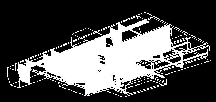
5 Graphic Representation (Geometry) Shading with Edge Wireframe Transparency Shading + Transparency
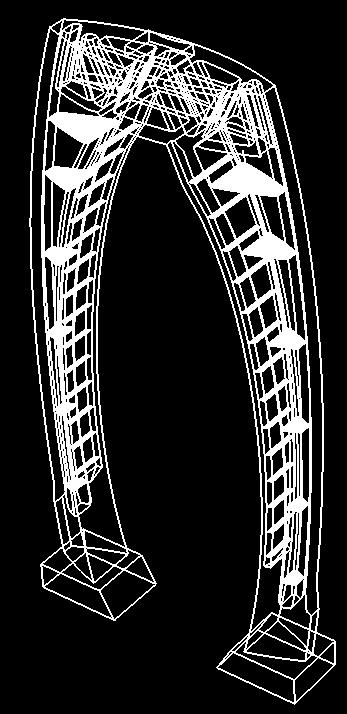
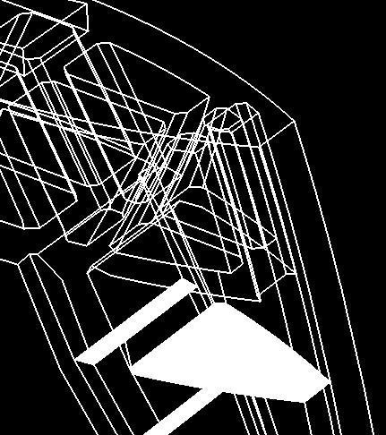
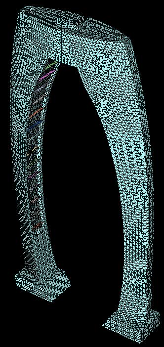

6 Graphic Representation (Mesh) Shrink Feature-Edge Wireframe (Free-Face) Shading Feature-Edge


7 Flying View
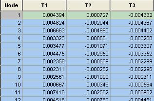
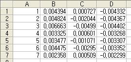
8 Benefits of FX4D (User Interface) Intuitive graphical user interface Windows based and CAD like user interface Easy to copy and paste into spreadsheets (MS-Excel) Easy access to desired task, command or model data Works Tree displays geometry, mesh, analysis and result data in a tree structure similar to Windows Explorer Property Window provides various information of selected item and allows change of basic properties such as name, color, material/property parameters, etc. MS-Excel compatible tables for nodes, elements, loads, constraints and results Various display options Shading, transparency, wireframe, bounding box, etc. (Combination allowed) Virtual Mesh Transformation Flying View for walk-through navigation Advanced selection methods Pick / window, circle, polyline, polygon, query pick, ID, etc. Dedicated selection filters for geometry and mesh entities

 Tunnel")
9 Geometry Modeling (Curve) Generation Modification Line Arc Circle Ellipse Parabola Hyperbola B-Spline Polyline Rectangle Polygon Profile Tunnel On-Surface Curve Shortest Path Line Surface Intersection Offset Curve Extrude Vertex Tangent Line Fillet / Chamfer Trim / Extend Merge / Break Intersect Align, Coincide Make Wire Arc Imported DXF Polyline Surface Intersection Line Circle Profile (Polyline+Tangent Arc) Tunnel Section B-Spline

10 Geometry Modeling (Surface/Solid) Generation Guide Curve Sweep Profile Extrude Profiles Loft Extrude Profile Revolve Loft Profiles


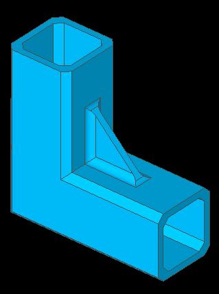


11 Geometry Modeling (Surface/Solid) Modification Trim Surfaces Local Prism (Fuse: Defined Height) Fillet Shell Offset Chamfer
12 Benefits of FX4D (Geometry Modeling) Advanced features for curve, surface and solid modeling Practical curve types: polyline, rectangle, B-spline, tunnel section, etc. Non-manifold surface modeling functions: sew, fuse, trim, divide, imprint, etc. Various solid primitives: box, cylinder, cone, torus, sphere, etc. CAD data exchange: AutoCAD DWG/DXF, ACIS, Parasolid, etc. CAD-like modeling functions Extrude, revolve, loft, sweep, local prism, fillet, chamfer, shell, etc. Powerful Boolean operation for solid modeling Fuse, cut, common, trim and embed Efficient and robust geometry checking & repairing tools Healing: split revolved surface, simplify surface, fix topology, etc. Repairing: merge/match/break sub-edges, merge surfaces, etc. Practical mouse snapping Coordinate input by mouse snapping (global & work plane) Grid, vertex, end, middle, intersection, center, quadrant, node, etc.


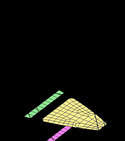
13 Surface Mesh Generation FX4D provides a number of modeling and meshing functions for non-manifold surface models. Check Mesh Non-manifold Connections Non-manifold Edge Free Edge


 is")


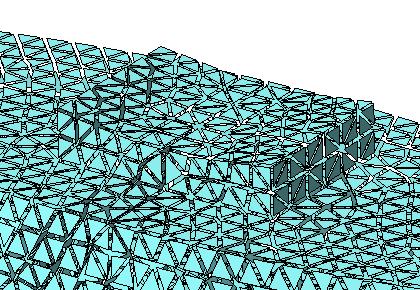
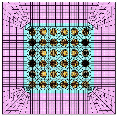
14 Automatic Solid Mesh Generation FX4D s Tetra Mesher auto-generates tetrahedral solid mesh with variable sizes in smooth transition. (200,000 Tetra s/min) FX4D s Tetra Mesher is capable of including holes, curves and points that are present in/on solids.


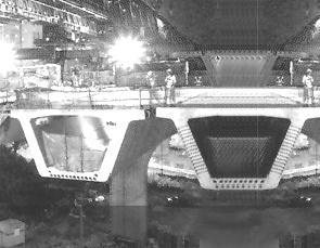
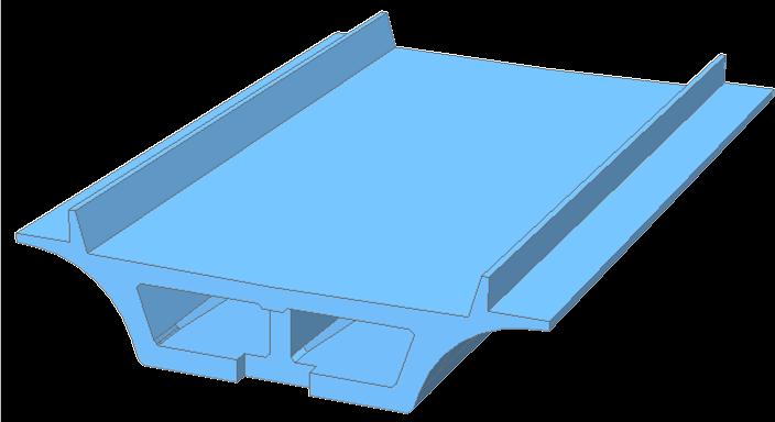
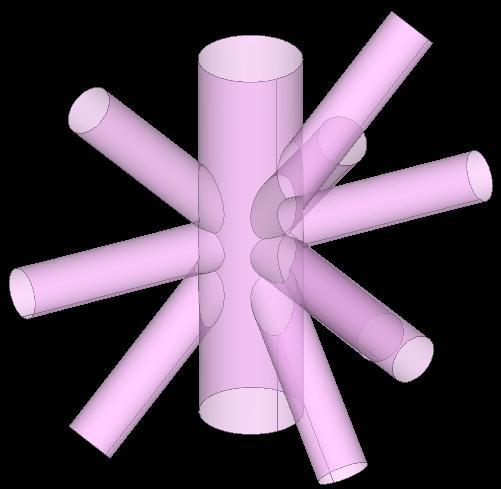
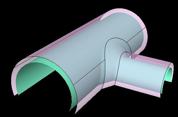
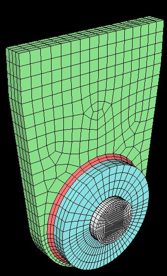
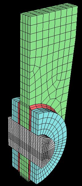
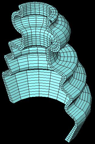
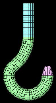
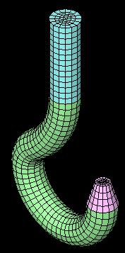
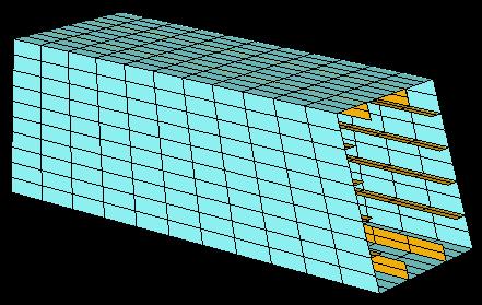
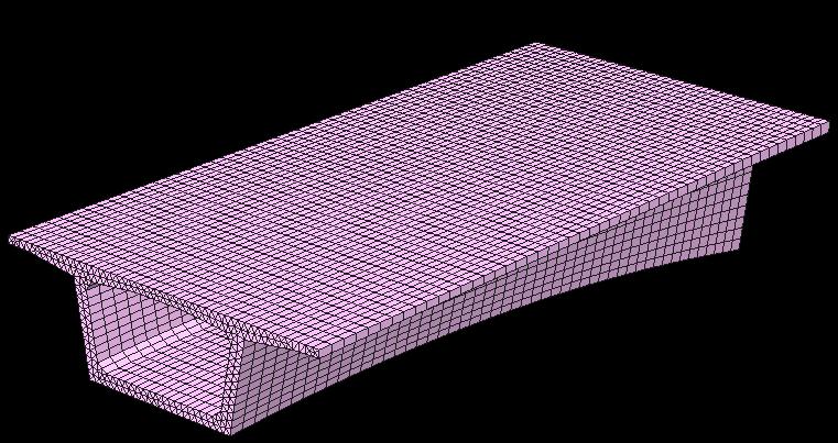
15 Mapped Mesh Generation FX4D s Map Mesher generates structured (regular & orthogonal) mesh both in surfaces and solids. k-sided Areas (Simply-connected) Pipe Junction Cargo Carrier Connection Part


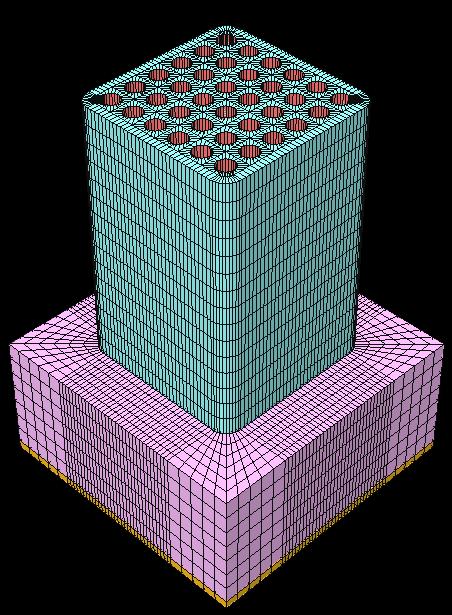

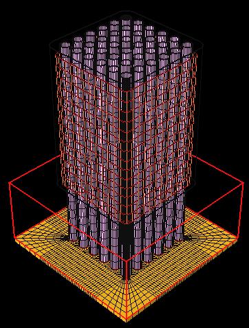
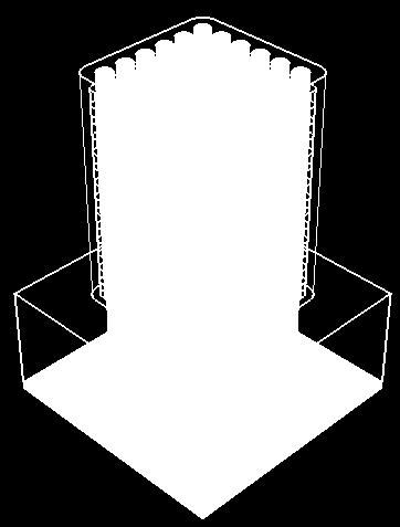
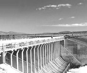
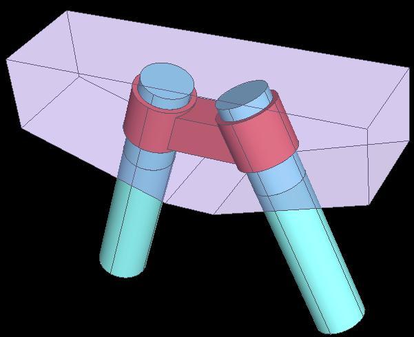
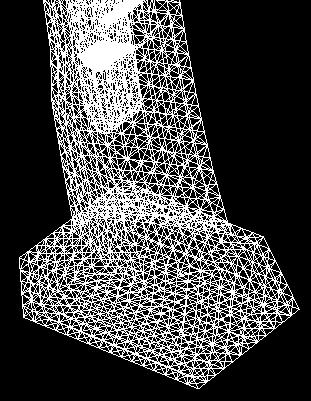
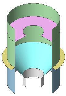
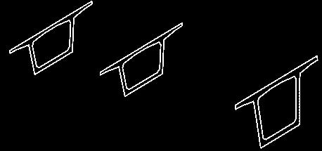
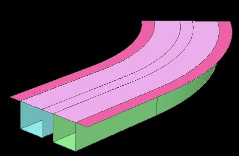
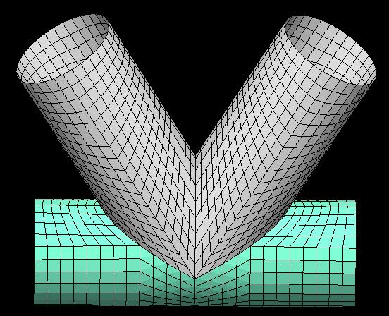
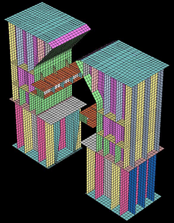
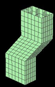
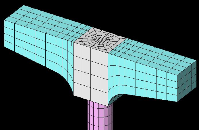
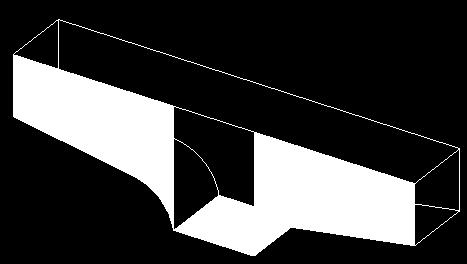
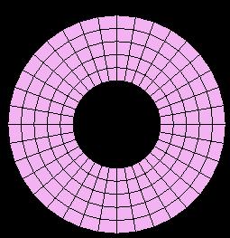
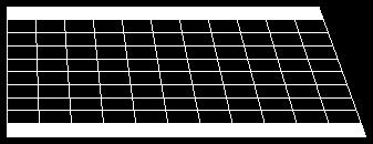
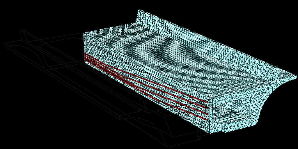
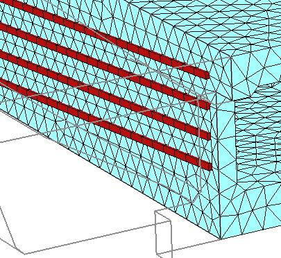
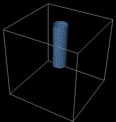
16 Mapped Mesh Generation FX4D s Solid Map Mesher generates hexa and/or penta mesh in simple solids by full mapping or combination (auto+map). Full Mapping (3D) Lug-Pin Joint Pier (Pipe + Reinforcement Steel + Concrete)


17 Mesh Protrusion Extrude (2D 3D) Fill (Curve 2D) Section Simulate Extrude thru Node Sequence (Curve 2D) Revolve (2D 3D)

18 Mesh Protrusion Fill (2D 3D) Project (Curve 3D) Top Same Topology Bottom Sweep (2D 3D) Guide Curve Scaled Sweep Offset (2D 3D)


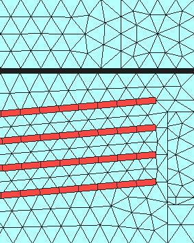

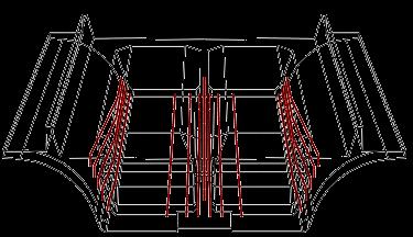
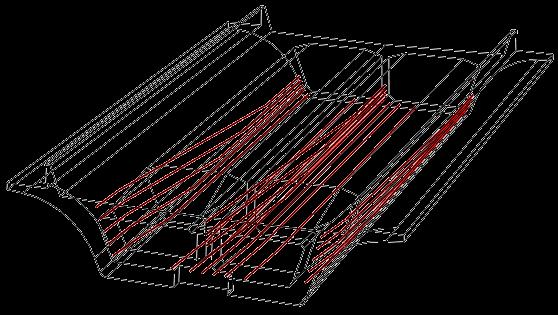
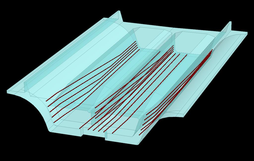
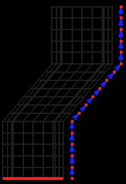
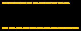
19 Reinforcement Elements Modeling Methods Embedded Bar (In-compatible Mesh) Truss (Compatible Mesh) + Interface (Slip, Friction) Prism Map-Mesh Embedded Bar (Incompatible) Truss + Interface (Compatible) Analysis Result


20 Interface Elements Generation Methods Select Nodes Input Node IDs Extract from Element Boundary Extract from Free-Faces Insert Both Sides of Beam/Plate Covert Elements Select Nodes Input Node IDs Extract from Element Boundary Extract from Free-Faces Insert Both Sides of Beam/Plate


21 Property Manager for DIANA Elements Tabs (Types) Color Types & Options Property Category Button Compatible Type List 1D Property Dialog (Beam) Section Template
22 Benefits of FX4D (Mesh Generation) Advanced features for mesh generation Extrude, revolve, fill, sweep, etc. Various easy & strong meshing algorithms for 1 st - and 2 nd -order elements Surface meshing: Looping, Delaunay, Grid-based approach and mapping Solid meshing: Tetra, full-mapping and combined mapping Both mesh and geometry based mesh generation Efficient size control methods Element length, division and biased seeding (length/ratio) Easy mesh manipulation Change property, order, normal, local csys., transformation, etc. Embedded reinforcements generation Automatic DIANA element type selection Dedicated element property manager for DIANA elements Categorized property management, copy, import, etc.


23 Load and Boundary Constraints Supported Functions Constraint Body Force Nodal Head Nodal / Surface Flux Force Moment Displacement Nodal Temperature Nodal Mass Initial Potential Pressure Element Beam Load Line Beam Load Prestress Element Temperature Concentration Maturity Pressure Head External Potential Prestress for Reinforcement Post Tension Heat Generation Arbitrary Point Load BC Set Load Set Constraint Tables Load Tables CSys-based Constraint Spatially Varying Pressure (Function Applied)
 Load Dialog")
24 Load and Boundary Constraints Load Set Element Type Table Equation-based Definition (supports mathematical expression) Object for Selection Operation Mode Graph Reset Value Input Preview Function Dialog (Spatial, Non-spatial: Time) Load Dialog (Prestress)

")

25 Load and Boundary Constraints Pre-Works Tree (Explorer-like) MS-Excel Load Table (Excel-compatible, Copy/Paste, Input/Delete)
26 Benefits of FX4D (LBCs) Full support of load and boundary conditions Including specific DIANA features like maturity, post-tensioning, pre-stress, etc. Both applicable on mesh and geometry entities Mesh: group, node and element Geometry: edge, wire, face and shell Provides Transfer to FE function which converts LBCs, assigned to geometry, to nodes or elements of geometry Function based definition Spatial and non-spatial (time) MS-Excel compatible tables Supports copy & paste operations Various display options for load and boundary constraints Symbol size: constant, proportional size to magnitude 3D symbols support vector (direction & magnitude) Symbol color, show/hide value, font size, etc.

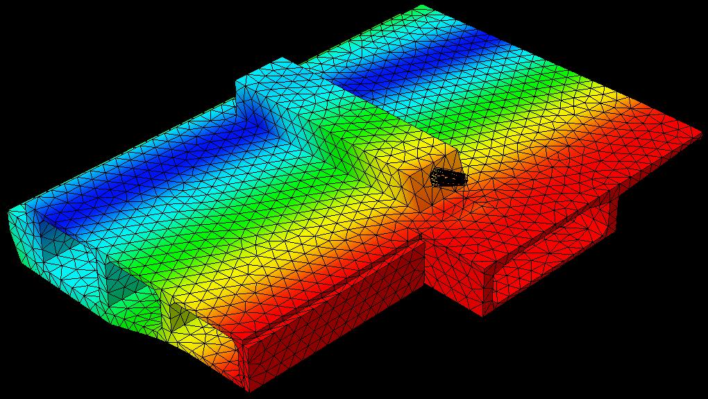
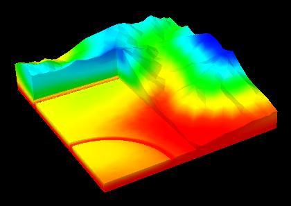
27 Post-processing Contour Plot Result Graph Works Tree MS-Excel Result Table


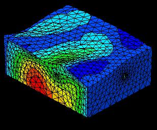
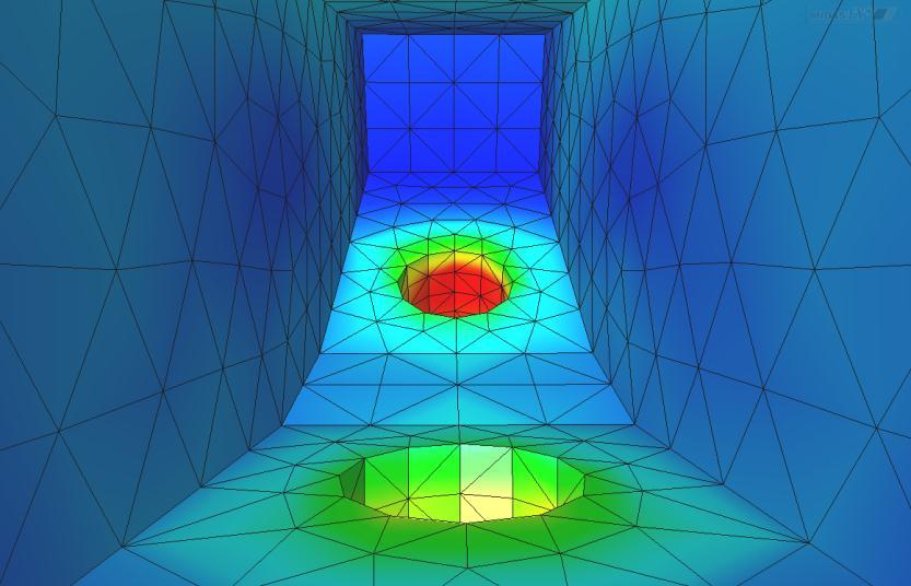
28 Contour Plot Type Contour with Mesh Contour with Iso-line Contour with Mesh & Iso-line Gradient Contour 2-Color Contour Gray Contour


29 Iso-surface Plot Iso-surface in Transparent Solid Geometry Capped Plot (Lower Part) Base Iso-surface Multiple Iso-surfaces Capped Plot (Upper Part)

")


30 Slice Plot Original Plot (Solid) Multiple Slice Planes Slice Plot at Arbitrary Plane


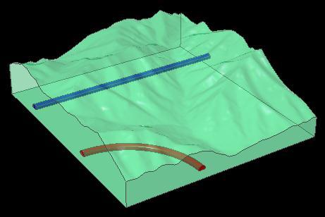
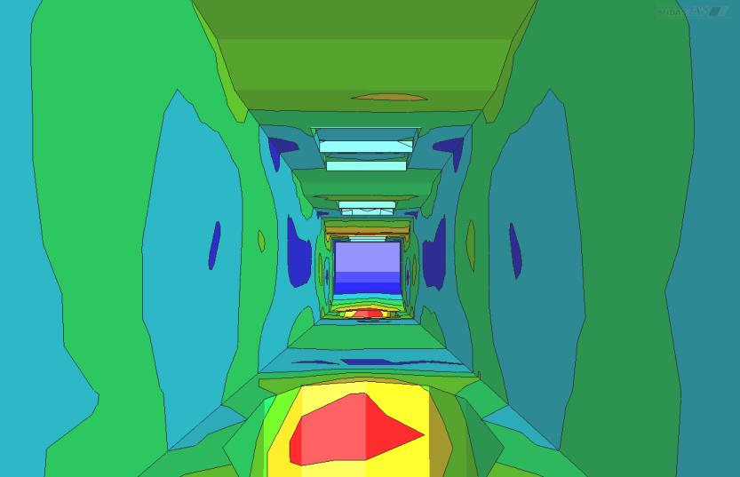
31 Clipping Plot Original Plot Multiple Clipping Planes


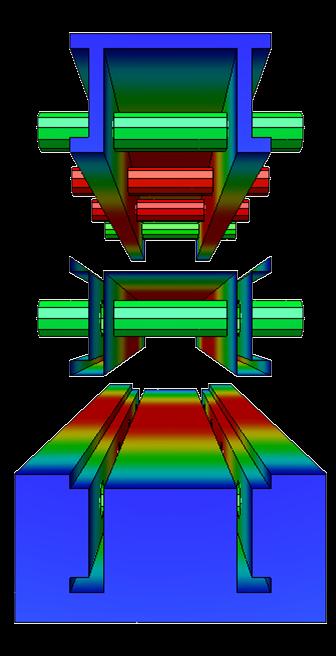

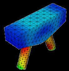
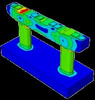
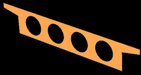
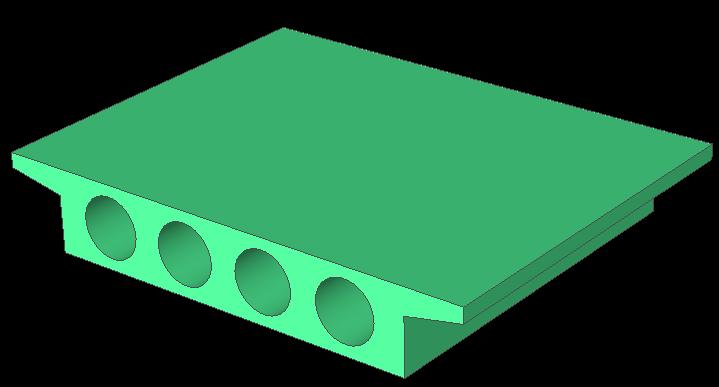
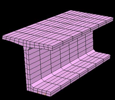
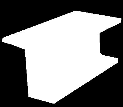
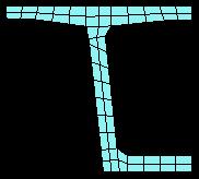
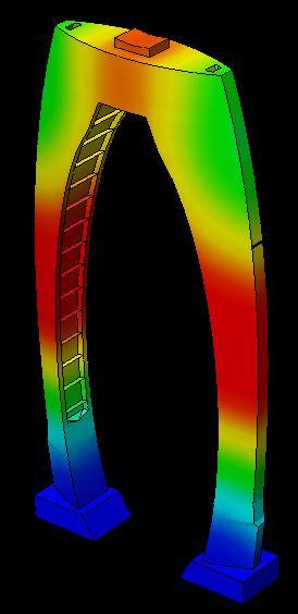
32 Partition Plot Steel Interface Concrete Steel-Concrete Composite Girder


33 Mirror Plot Symmetry Plane Symmetric Model Mirrored Contour Plot Mirrored Deformed Shape


34 Diagram Plot Solid Type Section Plot of Frames Diagram Plot with Deformed Shape Line Type

")


 with")


35 Vector Plot Vector Plot Option Head Type (Both, One, None) Constant Head Size Constant Body Size Color (Contour, Mono) Vector Plot with Deformation Vector Plot with Contour Vector Plot with Transparent Geometry
 Element Status Cracking:")


36 Crack Representation Results Crack Pattern (Crack Stress/Strain) Element Status Cracking: Partially/Fully Open, Closed, Not Yet Plasticity: Previously Plastic, Elastic, Plastic, Critical Contact: No Contact, Slip, Stick Symbols at Integration Points Disc Normal: Opening Direction Disc Color : Magnitude Line : Shearing Direction Steel Reinforced Concrete Bracket Crack Pattern (Disc Plot)

 Transient Analysis Results can be extracted")
 - Coordinate (User-defined")
37 Extract Results Start Step / Time End Step / Time Step / Output Set Result Type Node / Element IDs MS-Excel compatible Table (Time & Result Value) Graph (Time.vs. Result Value) Transient Analysis Results can be extracted based on: - Time (Transient Analysis) - Step (Nonlinear / Construction Stage Analysis) - Coordinate (User-defined Coordinate Sys.)


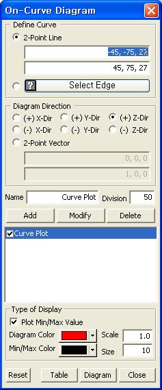
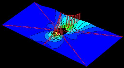
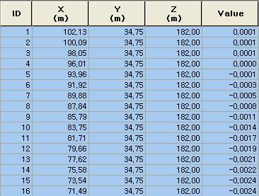
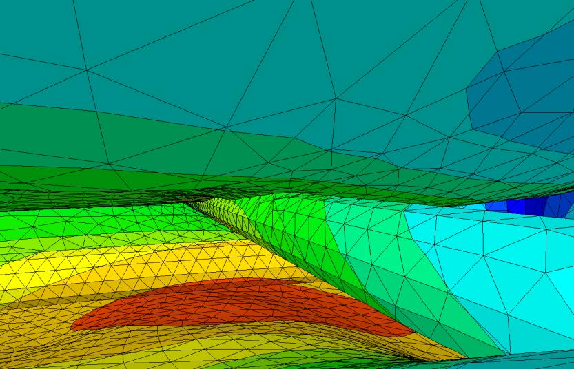
38 On-Curve Diagram 3D On-Curve Graphs on Contour Plot Result Data at User-Specified Sampling Points Fault Zone 2D On-Curve Graphs on Contour Plot Front View


")


39 Probe Result Sectional Result with Clipped Plot (Element Result) Nodal Result Probe & Add Result Tags at Specified Nodes/Elements
40 Benefits of FX4D (Post-processing) Complete solution to result interpretation Flexible user-control on legends, colors, fonts, magnification, etc. Multiple plots, graphs and tables in multiple windows Deformed shape combined with undeformed shape (including mode shape) Local plots defined by geometrical topology or user-selection Contour plots and animations (AVI, snap shots) Iso-value lines (2D) and surfaces (3D) Clipping planes and slice lines/planes Partitioned plots History plots in various graphs and animations (AVI) Result values in MS-Excel compatible tables Result probe and extraction Result extraction for construction stage analysis and time history analysis Screen-shots in WMF, BMP, PNG picture formats Works Tree, toolbar and Property Window-based operation and manipulation File I/O for configuration
41 Customized Pre/post-processor for DIANA FX for DIANA
DIANA FINITE ELEMENT ANALYSIS
 DIANA FINITE ELEMENT ANALYSIS DIANA FEA a TNO Company DIANA F I N I T E E L E M E N T A N A LY S I S DIANA (DIsplacement ANAlyzer) is a multi-purpose finite element program, with a special strength in
MIDAS/FEA. Advanced Nonlinear and Detailed Analysis Program. MIDAS Information Technology Co., Ltd.
 MIDAS/FEA Advanced Nonlinear and Detailed Analysis Program Analysis Capabilities Static Analysis Construction Stage Analysis Moving Load Analysis Modal Analysis Linear Buckling Analysis Transient / Frequency
DIANA. Finite Element Analysis. Civil Engineering Geotechnical Engineering Petroleum Engineering
 DIANA Finite Element Analysis Civil Engineering Geotechnical Engineering Petroleum Engineering NOW Advancing in new numerical analysis techniques Developing state-of-the-art solution for engineering applications
Advanced Webinar. Date: December 8, 2011 Topic: General Use of midas GTS (Part I) Presenter: Abid Ali, Geotechnical Engineer
 Presenter: Abid Ali, Geotechnical Engineer") midas GTS Advanced Webinar Date: December 8, 2011 Topic: General Use of midas GTS (Part I) Presenter: Abid Ali, Geotechnical Engineer Bridging Your Innovations to Realities Contents: 1. Introduction 2.
midas GTS Advanced Webinar Date: December 8, 2011 Topic: General Use of midas GTS (Part I) Presenter: Abid Ali, Geotechnical Engineer Bridging Your Innovations to Realities Contents: 1. Introduction 2.
Advanced Nonlinear and Detail Analysis Program
 Overview Overview Geometry Modeling Mesh Generation Analysis Post-processing 2 Overview About FEA FEA is a state-of-the art integrated finite element analysis system for nonlinear and detail simulations
Geometry Definition in the ADINA User Interface (AUI) Daniel Jose Payen, Ph.D. March 7, 2016
 Daniel Jose Payen, Ph.D. March 7, 2016") Geometry Definition in the ADINA User Interface (AUI) Daniel Jose Payen, Ph.D. March 7, 2016 ADINA R&D, Inc., 2016 1 Topics Presented ADINA에서쓰이는 Geometry 종류 Simple (AUI) geometry ADINA-M geometry ADINA-M
Geometry Definition in the ADINA User Interface (AUI) Daniel Jose Payen, Ph.D. March 7, 2016 ADINA R&D, Inc., 2016 1 Topics Presented ADINA에서쓰이는 Geometry 종류 Simple (AUI) geometry ADINA-M geometry ADINA-M
GTS. midas GTS Advanced Webinar. Date: June 5, 2012 Topic: General Use of midas GTS (Part II) Presenter: Vipul Kumar
 Presenter: Vipul Kumar") midas GTS Advanced Webinar Date: June 5, 2012 Topic: General Use of midas GTS (Part II) Presenter: Vipul Kumar Bridging Your Innovations to Realities GTS MIDAS Information Technology Co., Ltd. [1/30] Contents:
midas GTS Advanced Webinar Date: June 5, 2012 Topic: General Use of midas GTS (Part II) Presenter: Vipul Kumar Bridging Your Innovations to Realities GTS MIDAS Information Technology Co., Ltd. [1/30] Contents:
Eurocodes and Innovation. Developments in Finite Element Analysis for Bridges
 Eurocodes and Innovation Developments in Finite Element Analysis for Bridges Developments in Finite Element Analysis for Bridges Ease of Use Vehicle Loading - Autocombinations Cable Tuning Construction
SOLIDWORKS 2016: A Power Guide for Beginners and Intermediate Users
 SOLIDWORKS 2016: A Power Guide for Beginners and Intermediate Users The premium provider of learning products and solutions www.cadartifex.com Table of Contents Dedication... 3 Preface... 15 Part 1. Introducing
Input CAD Solid Model Assemblies - Split into separate Part Files. DXF, IGES WMF, EMF STL, VDA, Rhino Parasolid, ACIS
 General NC File Output List NC Code Post Processor Selection Printer/Plotter Output Insert Existing Drawing File Input NC Code as Geometry or Tool Paths Input Raster Image Files Report Creator and Designer
FEMAP FEMAP Modeler. Meshing: Subdivision and semi-automatic meshing of solids Automatic and mapped meshing (with quads or bricks), including biasing
, including biasing") FEMAP FEMAP Modeler Overview FEMAP V9.3 is a Windows-native pre- and post-processor used by engineering organizations world wide to model various products, processes, and systems. Its graphical user interface
FEMAP FEMAP Modeler Overview FEMAP V9.3 is a Windows-native pre- and post-processor used by engineering organizations world wide to model various products, processes, and systems. Its graphical user interface
SolidWorks. An Overview of SolidWorks and Its Associated Analysis Programs
 An Overview of SolidWorks and Its Associated Analysis Programs prepared by Prof. D. Xue University of Calgary SolidWorks - a solid modeling CAD tool. COSMOSWorks - a design analysis system fully integrated
3. Preprocessing of ABAQUS/CAE
 3.1 Create new model database 3. Preprocessing of ABAQUS/CAE A finite element analysis in ABAQUS/CAE starts from create new model database in the toolbar. Then save it with a name user defined. To build
World-class finite element analysis (FEA) solution for the Windows desktop
 solution for the Windows desktop") World-class finite element analysis (FEA) solution for the Windows desktop fact sheet Siemens PLM Software www.siemens.com/plm/femap Summary Femap software is an advanced engineering analysis environment
World-class finite element analysis (FEA) solution for the Windows desktop fact sheet Siemens PLM Software www.siemens.com/plm/femap Summary Femap software is an advanced engineering analysis environment
Version 2011 R1 - Router
 GENERAL NC File Output List NC Code Post Processor Selection Printer/Plotter Output Insert Existing Drawing File Input NC Code as Geometry or Tool Paths Input Raster Image Files Convert Raster to Vector
FEMAP All Rights Reserved NASTRAN 1
 FEMAP 1 Overview Femap V10.3 is a Windows-native pre- and postprocessor used by engineering organizations world wide to model various products, processes, and systems. Its graphical user interface provides
midas FEA V320 Table of Contents
 midas FEA V320 New Feature 01 CFD Moving Mesh Pre Process 01 File Open > File Preview 02 Extract Surface 03 Frame to Solid > Import 04 Tetra Auto mesh generation 05 Mesh options 06 Auto mesh Solid Function
Module 1: Basics of Solids Modeling with SolidWorks
 Module 1: Basics of Solids Modeling with SolidWorks Introduction SolidWorks is the state of the art in computer-aided design (CAD). SolidWorks represents an object in a virtual environment just as it exists
SOLIDWORKS 2016 and Engineering Graphics
 SOLIDWORKS 2016 and Engineering Graphics An Integrated Approach Randy H. Shih SDC PUBLICATIONS Better Textbooks. Lower Prices. www.sdcpublications.com Powered by TCPDF (www.tcpdf.org) Visit the following
Version 4.1 Demo. RecurDynTM 2002 RecurDyn User Conference
 Version 4.1 Demo RecurDynTM 2002 RecurDyn User Conference What s New? Using Parasolid Kernel Solid Modeler Other Program Interfaces New Data Structure New & Improved Features What s New? Using Parasolid
SOLIDWORKS - SYLLABUS
 SOLIDWORKS - SYLLABUS SolidWorks Syllabus 1 Introduction to CAD, CAE, PDM Features of SolidWorks, Total Duration : 90 Hour Various products available in SolidWorks for Product Design, Simulation, Communication
Lateral Loading of Suction Pile in 3D
 Lateral Loading of Suction Pile in 3D Buoy Chain Sea Bed Suction Pile Integrated Solver Optimized for the next generation 64-bit platform Finite Element Solutions for Geotechnical Engineering 00 Overview
Geometric Modeling Systems
 Geometric Modeling Systems Wireframe Modeling use lines/curves and points for 2D or 3D largely replaced by surface and solid models Surface Modeling wireframe information plus surface definitions supports
SimLab Release Notes. 1 A l t a i r E n g i n e e r i n g
 SimLab 11.0 Release Notes 1 A l t a i r E n g i n e e r i n g System Support extended to load and save GDA/SLB files of size greater than 4GB. Memory allocation is enhanced to support large models. Kubrix
VALLIAMMAI ENGINEERING COLLEGE
 VALLIAMMAI ENGINEERING COLLEGE SRM Nagar, Kattankulathur 603 203 DEPARTMENT OF MECHANICAL ENGINEERING QUESTION BANK M.E: CAD/CAM I SEMESTER ED5151 COMPUTER APPLICATIONS IN DESIGN Regulation 2017 Academic
CATIA Surface Design
 CATIA V5 Training Exercises CATIA Surface Design Version 5 Release 19 September 2008 EDU_CAT_EN_GS1_FX_V5R19 Table of Contents (1/2) Creating Wireframe Geometry: Recap Exercises 4 Creating Wireframe Geometry:
A Comprehensive Introduction to SolidWorks 2011
 A Comprehensive Introduction to SolidWorks 2011 Godfrey Onwubolu, Ph.D. SDC PUBLICATIONS www.sdcpublications.com Schroff Development Corporation Chapter 2 Geometric Construction Tools Objectives: When
NEi FEA. IRONCAD Advanced FEA. IRONCAD Advanced FEA. NEi FEA
 2011 Overview has been designed as a universal, adaptive and user-friendly graphical user interface for geometrical modeling, data input and visualization of results for all types of numerical simulation
World-class finite element analysis (FEA) solution for the Windows desktop
 solution for the Windows desktop") World-class finite element analysis (FEA) solution for the Windows desktop Benefits Significantly speed up the design process by bringing simulation closer to design and reducing time-to-market Reduce
World-class finite element analysis (FEA) solution for the Windows desktop Benefits Significantly speed up the design process by bringing simulation closer to design and reducing time-to-market Reduce
Introduction to ANSYS DesignModeler
 Lecture 5 Modeling 14. 5 Release Introduction to ANSYS DesignModeler 2012 ANSYS, Inc. November 20, 2012 1 Release 14.5 Preprocessing Workflow Geometry Creation OR Geometry Import Geometry Operations Meshing
SolidWorks 2013 and Engineering Graphics
 SolidWorks 2013 and Engineering Graphics An Integrated Approach Randy H. Shih SDC PUBLICATIONS Schroff Development Corporation Better Textbooks. Lower Prices. www.sdcpublications.com Visit the following
Exercise Guide. Published: August MecSoft Corpotation
 VisualCAD Exercise Guide Published: August 2018 MecSoft Corpotation Copyright 1998-2018 VisualCAD 2018 Exercise Guide by Mecsoft Corporation User Notes: Contents 2 Table of Contents About this Guide 4
AutoCAD for Engineers and Designers, 21st Edition. (3D and Advanced)
") AutoCAD 2015 for Engineers and Designers, 21st Edition (3D and Advanced) CADCIM Technologies 525 St. Andrews Drive Schererville, IN 46375, USA (www.cadcim.com) Contributing Author Sham Tickoo Professor
AutoCAD 2015 for Engineers and Designers, 21st Edition (3D and Advanced) CADCIM Technologies 525 St. Andrews Drive Schererville, IN 46375, USA (www.cadcim.com) Contributing Author Sham Tickoo Professor
DIANA 10 Finite Element Analysis. Civil Engineering Geotechnical Engineering Petroleum Engineering
 DIANA 10 Finite Element Analysis Civil Engineering Geotechnical Engineering Petroleum Engineering History of TNO DIANA 1972 TNO Department of Computational Mechanics 1975 Start of DIANA (Displacement ANAlyzer)
3D ModelingChapter1: Chapter. Objectives
 Chapter 1 3D ModelingChapter1: The lessons covered in this chapter familiarize you with 3D modeling and how you view your designs as you create them. You also learn the coordinate system and how you can
3D Modeling and Design Glossary - Beginner
 3D Modeling and Design Glossary - Beginner Align: to place or arrange (things) in a straight line. To use the Align tool, select at least two objects by Shift left-clicking on them or by dragging a box
GTS NX INTERFACES AUTOCAD MIDAS GEN FOR TUNNEL SOIL PILE INTERACTION ANALYSIS
 INTERFACES AUTOCAD MIDAS GEN FOR TUNNEL SOIL PILE INTERACTION ANALYSIS Angel F. Martinez Civil Engineer MIDASOFT Integrated Solver Optimized for the next generation 64-bit platform Finite Element Solutions
Convergent Modeling and Reverse Engineering
 Convergent Modeling and Reverse Engineering 25 October 2017 Realize innovation. Tod Parrella NX Design Product Management Product Engineering Solutions tod.parrella@siemens.com Realize innovation. Siemens
Lecture 4, 5/27/2017, Rhino Interface an overview
 數字建築與城市设计 Spring 2017 Lecture 4, 5/27/2017, Rhino Interface an overview Copyright 2017, Chiu-Shui Chan. All Rights Reserved. This lecture concentrates on the use of tools, 3D solid modeling and editing
Autodesk Inventor 2019 and Engineering Graphics
 Autodesk Inventor 2019 and Engineering Graphics An Integrated Approach Randy H. Shih SDC PUBLICATIONS Better Textbooks. Lower Prices. www.sdcpublications.com Powered by TCPDF (www.tcpdf.org) Visit the
Analysis Steps 1. Start Abaqus and choose to create a new model database
 Source: Online tutorials for ABAQUS Problem Description The two dimensional bridge structure, which consists of steel T sections (b=0.25, h=0.25, I=0.125, t f =t w =0.05), is simply supported at its lower
Engineering Drawing II
 Instructional Unit Basic Shading and Rendering -Basic Shading -Students will be able -Demonstrate the ability Class Discussions 3.1.12.B, -Basic Rendering to shade a 3D model to apply shading to a 3D 3.2.12.C,
TABLE OF CONTENTS WHAT IS ADVANCE DESIGN? INSTALLING ADVANCE DESIGN... 8 System requirements... 8 Advance Design installation...
 Starting Guide 2019 TABLE OF CONTENTS INTRODUCTION... 5 Welcome to Advance Design... 5 About this guide... 6 Where to find information?... 6 Contacting technical support... 6 WHAT IS ADVANCE DESIGN?...
COMPUTER AIDED ARCHITECTURAL GRAPHICS FFD 201/Fall 2013 HAND OUT 1 : INTRODUCTION TO 3D
 COMPUTER AIDED ARCHITECTURAL GRAPHICS FFD 201/Fall 2013 INSTRUCTORS E-MAIL ADDRESS OFFICE HOURS Özgür Genca ozgurgenca@gmail.com part time Tuba Doğu tubadogu@gmail.com part time Şebnem Yanç Demirkan sebnem.demirkan@gmail.com
Acknowledgement INTRODUCTION
 Submitted by: 1 Acknowledgement INTRODUCTION Computers are increasingly being used for doing engineering drawings and graphics work because computers allow the graphics designer or the draughtsman to change
Education Curriculum Surface Design Specialist
 Education Curriculum Surface Design Specialist Invest your time in imagining next generation designs. Here s what we will teach you to give shape to your imagination. CATIA Surface Design Specialist CATIA
Each trainee receives the official 260 page courseware as part of attending this course.
 Level 1 NURBS modelling with Rhino Course Outline This course is for anyone new, or nearly new, to Rhino. Recognised as THE introductory course for Rhino, all trainees receive an Official Certificate on
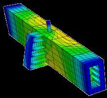
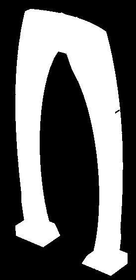
In-plane principal stress output in DIANA
 analys: linear static. class: large. constr: suppor. elemen: hx24l solid tp18l. load: edge elemen force node. materi: elasti isotro. option: direct. result: cauchy displa princi stress total. In-plane
Autodesk 123D Beta5 Overview
 Autodesk 123D Beta5 Overview Welcome. This overview document for Autodesk 123D will assist you in developing your understanding of the software and how you can use it to create your design ideas. Designing
Appendix B: Creating and Analyzing a Simple Model in Abaqus/CAE
 Getting Started with Abaqus: Interactive Edition Appendix B: Creating and Analyzing a Simple Model in Abaqus/CAE The following section is a basic tutorial for the experienced Abaqus user. It leads you
Lesson 4: Surface Re-limitation and Connection
 Lesson 4: Surface Re-limitation and Connection In this lesson you will learn how to limit the surfaces and form connection between the surfaces. Lesson contents: Case Study: Surface Re-limitation and Connection
form.z features Comparison Chart
 form.z features Comparison Chart Modeling Accurate robust internal representation of data including 3D solids, surfaces, trimmed surfaces, NURBS and parametric representations. ACIS modeling engine provides
ATENA Program Documentation Part 4-2. Tutorial for Program ATENA 3D. Written by: Jan Červenka, Zdenka Procházková, Tereza Sajdlová
 Červenka Consulting s.ro. Na Hrebenkach 55 150 00 Prague Czech Republic Phone: +420 220 610 018 E-mail: cervenka@cervenka.cz Web: http://www.cervenka.cz ATENA Program Documentation Part 4-2 Tutorial for
3D Design with 123D Design
 3D Design with 123D Design Introduction: 3D Design involves thinking and creating in 3 dimensions. x, y and z axis Working with 123D Design 123D Design is a 3D design software package from Autodesk. A
Lesson 5 Solid Modeling - Constructive Solid Geometry
 AutoCAD 2000i Tutorial 5-1 Lesson 5 Solid Modeling - Constructive Solid Geometry Understand the Constructive Solid Geometry Concept. Create a Binary Tree. Understand the basic Boolean Operations. Create
SimLab 14.2 Release Notes
 SimLab 14.2 Release Notes Highlights SimLab 14.2 comes with various changes that improve performance and graphics rendering. In addition to java scripting, python scripting is introduced. The enhancements,
SIMULATION CAPABILITIES IN CREO
 SIMULATION CAPABILITIES IN CREO Enhance Your Product Design with Simulation & Using digital prototypes to understand how your designs perform in real-world conditions is vital to your product development
CATIA V5 Analysis. CATIA V5 Training Foils. CATIA V5 Analysis. Copyright DASSAULT SYSTEMES 1. Student Notes:
 CATIA V5 Training Foils CATIA V5 Analysis Version 5 Release 19 January 2009 EDU_CAT_EN_V5A_FF_V5R19 1 Lesson 1: Introduction to Finite Element Analysis About this Course Introduction CATIA is a robust
Create Complex Surfaces
 Create Complex Surfaces In this lesson, you will be introduced to the functionalities available in the Generative Surface Design workbench. Lesson content: Case Study: Surface Design Design Intent Stages
Assessment TESTS SLO #1 CADD 131
 CADD 131 Assessment TESTS 1- SLO #1 1. Of what does a mesh model consist? 2. What is another term for mesh models? 3. What are tessellation divisions? 4. When creating a mesh primitive, when should mesh
Geometry Clean-up in. Numerical Simulations
 Geometry Clean-up in Numerical Simulations Scope of the this Presentation The guidelines are very generic in nature and has been explained with examples. However, the users may need to check their software
L1 - Introduction. Contents. Introduction of CAD/CAM system Components of CAD/CAM systems Basic concepts of graphics programming
 L1 - Introduction Contents Introduction of CAD/CAM system Components of CAD/CAM systems Basic concepts of graphics programming 1 Definitions Computer-Aided Design (CAD) The technology concerned with the
Additional Surface Tools
 Additional Surface Tools Several additional surface tools, techniques, and related functions are available. This supplement provides a brief introduction to those functions. Panel Part Features Replace
Geometric Modeling. Introduction
 Geometric Modeling Introduction Geometric modeling is as important to CAD as governing equilibrium equations to classical engineering fields as mechanics and thermal fluids. intelligent decision on the
Overview of ABAQUS II. Working with Geometry in ABAQUS III. Working with models Created Outside ABAQUS IV. Material and Section Properties
 ABAQUS TRAINING I. Overview of ABAQUS II. Working with Geometry in ABAQUS III. Working with models Created Outside ABAQUS IV. Material and Section Properties V. Assemblies in ABAQUS VI. Steps, Output,
Creating and Analyzing a Simple Model in Abaqus/CAE
 Appendix B: Creating and Analyzing a Simple Model in Abaqus/CAE The following section is a basic tutorial for the experienced Abaqus user. It leads you through the Abaqus/CAE modeling process by visiting
Embedded Reinforcements
 Embedded Reinforcements Gerd-Jan Schreppers, January 2015 Abstract: This paper explains the concept and application of embedded reinforcements in DIANA. Basic assumptions and definitions, the pre-processing
Tips and tricks. AutoCAD 2010
 Tips and tricks AutoCAD 2010 Parametric Drawing Powerful new parametric drawing functionality in AutoCAD 2010 enables you to dramatically increase productivity by constraining drawing objects based on
midas Civil Advanced Webinar Date: February 9th, 2012 Topic: General Use of midas Civil Presenter: Abhishek Das Bridging Your Innovations to Realities
 Advanced Webinar Date: February 9th, 2012 Topic: General Use of midas Civil Presenter: Abhishek Das Contents: Overview Modeling Boundary Conditions Loading Analysis Results Design and Misc. Introduction
Finite Element Analysis Using Creo Simulate 4.0
 Introduction to Finite Element Analysis Using Creo Simulate 4.0 Randy H. Shih SDC PUBLICATIONS Better Textbooks. Lower Prices. www.sdcpublications.com Powered by TCPDF (www.tcpdf.org) Visit the following
Spring 2011 Workshop ESSENTIALS OF 3D MODELING IN RHINOCEROS February 10 th 2011 S.R. Crown Hall Lower Core Computer Lab
 [1] Open Rhinoceros. PART 1 INTRODUCTION [4] Click and hold on the Boundary Lines in where they form a crossing and Drag from TOP RIGHT to BOTTOM LEFT to enable only the PERSPECTIVE VIEW. [2] When the
Create the Through Curves surface
 Create the Through Curves surface 1. Open ffm4_mc_fender. 2. Select all three strings, and then on the Analyze Shape toolbar, click Show End Points. Notice there are two curves in the strings on the left
Solid Modeling: Part 1
 Solid Modeling: Part 1 Basics of Revolving, Extruding, and Boolean Operations Revolving Exercise: Stepped Shaft Start AutoCAD and use the solid.dwt template file to create a new drawing. Create the top
Chapter 9 3D Modeling
 Chapter 9 3D Modeling Copyright The McGraw-Hill Companies, Inc. Permission required for reproduction or display. 3D Modeling Snapshot Since Mid 1980 s become common place in industry Software Types Wireframe
pre- & post-processing f o r p o w e r t r a i n
 pre- & post-processing f o r p o w e r t r a i n www.beta-cae.com With its complete solutions for meshing, assembly, contacts definition and boundary conditions setup, ANSA becomes the most efficient and
NX Advanced FEM. Benefits
 Advanced FEM fact sheet Siemens PLM Software www.siemens.com/plm Summary Advanced FEM software is a comprehensive multi-cad finite element modeling and results visualization product that is designed to
CATIA V5 Parametric Surface Modeling
 CATIA V5 Parametric Surface Modeling Version 5 Release 16 A- 1 Toolbars in A B A. Wireframe: Create 3D curves / lines/ points/ plane B. Surfaces: Create surfaces C. Operations: Join surfaces, Split & Trim
Table of Contents Memory Management... 3 Results Enveloping... 5 Set Random Property Colors... 8 Model Box Extend Merge Mesh...
 1 Table of Contents Memory Management... 3 Results Enveloping... 5 Set Random Property Colors... 8 Model Box... 11 Extend Merge Mesh... 13 NonManifold Add... 16 Element Visual Inspection... 18 Graphical
Geometric Modeling Topics
 Geometric Modeling Topics George Allen, george.allen@siemens.com Outline General background Convergent modeling Multi-material objects Giga-face lattices Page 2 Boundary Representation (b-rep) Topology
NX Advanced FEM. fact sheet
 Advanced FEM fact sheet www.ugs.com Summary Advanced FEM is a comprehensive multi-cad finite element modeling and results visualization product that is designed to meet the needs of experienced CAE analysts.
Images from 3D Creative Magazine. 3D Modelling Systems
 Images from 3D Creative Magazine 3D Modelling Systems Contents Reference & Accuracy 3D Primitives Transforms Move (Translate) Rotate Scale Mirror Align 3D Booleans Deforms Bend Taper Skew Twist Squash
CONTENTS. PART I. Getting Started. 1. Introduction. 2. Installation. 3. Understanding midas FEA
 1 CONTENTS PART I. Getting Started 1. Introduction 1.1 Introduction ------------------------------------------------------------------------------------ Ⅰ-1-1 2. Installation 2.1 System Requirements ----------------------------------------------------------------------
BobCAD CAM V25 4 Axis Standard Posted by Al /09/20 22:03
 BobCAD CAM V25 4 Axis Standard Posted by Al - 2012/09/20 22:03 Many BobCAD CAM clients that run a 4 axis have requested to work directly with Solids or STL files. In the past we only offered 4 axis indexing
Introduction to Solid Modeling Parametric Modeling. Mechanical Engineering Dept.
 Introduction to Solid Modeling Parametric Modeling 1 Why draw 3D Models? 3D models are easier to interpret. Simulation under real-life conditions. Less expensive than building a physical model. 3D models
SolidWorks 2014 Part II - Advanced Techniques
 SolidWorks 2014 Part II - Advanced Techniques Parts, Surfaces, Sheet Metal, SimulationXpress, Top-Down Assemblies, Core and Cavity Molds Paul Tran CSWE, CSWI SDC PUBLICATIONS Better Textbooks. Lower Prices.
Solidworks 2006 Surface-modeling
 Solidworks 2006 Surface-modeling (Tutorial 2-Mouse) Surface-modeling Solid-modeling A- 1 Assembly Design Design with a Master Model Surface-modeling Tutorial 2A Import 2D outline drawing into Solidworks2006
What s new in Femap 9.3
 What s new in Femap 9.3 fact sheet www.ugs.com/femap Summary Femap version 9.3 is the latest release of UGS robust pre and post processor for engineering finite element analysis (FEA). Femap software is
Abaqus CAE Tutorial 1: 2D Plane Truss
 ENGI 7706/7934: Finite Element Analysis Abaqus CAE Tutorial 1: 2D Plane Truss Lab TA: Xiaotong Huo EN 3029B xh0381@mun.ca Download link for Abaqus student edition: http://academy.3ds.com/software/simulia/abaqus-student-edition/
Computer Aided Engineering Applications
 Computer Aided Engineering Applications 1A.Geometric Modeling 1.1 Geometric modelling methods 1.2 Data representation 1.3 Modeling functions 1.4 Structure of a CAD system Engi 6928 - Fall 2014 1.Geometric
SOLIDWORKS 2019 Advanced Techniques
 SOLIDWORKS 2019 Advanced Techniques Mastering Parts, Surfaces, Sheet Metal, SimulationXpress, Top Down Assemblies, Core & Cavity Molds Paul Tran CSWE, CSWI SDC PUBLICATIONS Better Textbooks. Lower Prices.
3 AXIS STANDARD CAD. BobCAD-CAM Version 28 Training Workbook 3 Axis Standard CAD
 3 AXIS STANDARD CAD This tutorial explains how to create the CAD model for the Mill 3 Axis Standard demonstration file. The design process includes using the Shape Library and other wireframe functions
3D Soil Modelling (Geometry)
") 3D Soil Modelling (Geometry) Soil Profiling1 Description: This step shows how to import bolehole log data from a spreadsheet into GTS in preparation of soil modelling. Step 1. 1. Open GTS.exe 2. Main Menu:
3D Soil Modelling (Geometry) Soil Profiling1 Description: This step shows how to import bolehole log data from a spreadsheet into GTS in preparation of soil modelling. Step 1. 1. Open GTS.exe 2. Main Menu:
Torsional-lateral buckling large displacement analysis with a simple beam using Abaqus 6.10
 Torsional-lateral buckling large displacement analysis with a simple beam using Abaqus 6.10 This document contains an Abaqus tutorial for performing a buckling analysis using the finite element program
Additional Exercises. You will perform the following exercises to practice the concepts learnt in this course:
 Additional Exercises You will perform the following exercises to practice the concepts learnt in this course: Master Exercise : Mobile Phone Plastic Bottle Exercise 1 Master Exercise : Mobile Phone In
CE Advanced Structural Analysis. Lab 4 SAP2000 Plane Elasticity
 Department of Civil & Geological Engineering COLLEGE OF ENGINEERING CE 463.3 Advanced Structural Analysis Lab 4 SAP2000 Plane Elasticity February 27 th, 2013 T.A: Ouafi Saha Professor: M. Boulfiza 1. Rectangular
ANSYS AIM Tutorial Structural Analysis of a Plate with Hole
 ANSYS AIM Tutorial Structural Analysis of a Plate with Hole Author(s): Sebastian Vecchi, ANSYS Created using ANSYS AIM 18.1 Problem Specification Pre-Analysis & Start Up Analytical vs. Numerical Approaches
solidthinking Design Release Notes
 solidthinking Design 2017.2 Release Notes The solidthinking Design package includes Inspire and Evolve 2017.2. Inspire is available on Windows, while Evolve is available on Windows and Mac. solidthinking
Tutorial 4 Arch Bridge
 Tutorial 4 Arch Bridge Civil TUTORIAL 4. ARCH BRIDGE Summary 1 Analysis Model and Load Cases / 2 File Opening and Preferences Setting 5 Enter Material and Section Properties 6 Structural Modeling Using
Tutorial Second Level
 AutoCAD 2018 Tutorial Second Level 3D Modeling Randy H. Shih SDC PUBLICATIONS Better Textbooks. Lower Prices. www.sdcpublications.com Powered by TCPDF (www.tcpdf.org) Visit the following websites to learn
NX I-deas MasterFEM Complete standalone capabilities for creating FE models and evaluating simulation results
 I-deas MasterFEM Complete standalone capabilities for creating FE models and evaluating simulation results fact sheet Siemens PLM Software www.siemens.com/nx Summary I-deas MasterFEM software is the standalone