Practical modeling of diaphragm walls and foundation rafts with piles part I
|
|
|
- Monica Shields
- 5 years ago
- Views:
Transcription
1 Practical modeling of diaphragm walls and foundation rafts with piles part I
2 FE mesh This example concerns modeling of a deep excavation protected by concrete wall an then by a construction of foundation raft strengthened by bored piles. Foundation supports 11th storey building.
3 Horizontal cross section Diaphragm wall slab Dimension of the excavation is 90 m by 60 m in horizontal cross section.
4 Engineering draft 10 kn/m 2 Slabs thickness 30 cm 1 st stage 3.5 m 2 nd stage 3 rd stage 4 th stage -5 m 3.5 m 3.5 m 3.5 m 1.0 m m plate 13.0 m Diaphragm wall Excavation is protected by 0.8 m thick concrete wall and will be performed in four steps up to level m. Ground water table is at level -5.0 m. One meter thick plate is strengthen by ten meters long bored piles. Outside the excavation surface load of magnitude 10 kn/m2 is applied.


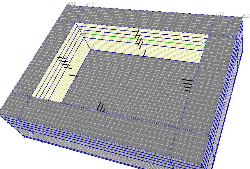
5 Model components Nodal links connection of nonconforming meshes Continuum 3D Piles Interface elements between diaphragm walls and soil shells

6 Box shaped solid boundary conditions and pressure boundary conditions for deformation and flow analysis have to be defined. Boundary conditions Pressure boundary conditions Solid boundary conditions Pressure head Seepage elements


7 Loads Surface load 10 kn/m 2 Nodal loads Surface load outside of excavation zone is applied to the soil and surface. Nodal loads are applied to foundation plate.

8 Model definition strategy internal.inp external.inp slabs.inp In order to simplify model generation, model will be defined in three parts: external, internal and building. External part contains soil close to model boundary with coarse mesh in order to decrease number of degrees of freedom in the analysis. Internal part contains excavation zone with diaphragm walls and foundation plate. Building with shells and beams will defined in third part. All parts will merged into one model.


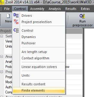
9 Run ZSoil 1. In Preselection screen select : - Analysis type: 3D - Problem type: Deformation + Flow Project preselection dialog box appears automatically when Zsoil Menu is started or for option File/New. Preselection can be changed in ZSoil Menu or/and in ZSoil Preprocessor:


10 Import data settings Definition of the material properties, load and existence functions and drivers will be skipped in this tutorial. All these settings will be imported from INP file.
11 Existence functions The sequence of excavation/construction stages is controlled by the existence functions, which are defined according to the sequence of events specified in the table below. Construction stage Time Action Initial state 0 Wall installation 1 Wall and interface on the wall 1 st excavation 10 excavation up to level -3.5 m Seepage on the level 0.0 m has to be removed Seepage on the level -3.5 m has to be defined 1 st slab 30 Slab at the level -3.5 has to be defined 2 nd excavation 30 excavation up to level -7.0 m Seepage on the level -3.5 m has to be removed Seepage on the level -7.0 m has to be defined 2 nd slab 50 Slab at the level -7.0 has to be defined 3 rd excavation 50 excavation up to level m Seepage on the level -7.0 m has to be removed Seepage on the level m has to be defined
12 Existence functions Construction stage Time Action 3 rd slab 70 Slab at the level has to be defined 4 th excavation 70 excavation up to level -15 m Seepage on the level m has to be removed Seepage on the level m has to be defined Piles 75 Plate 80

13 Click on this button to display next selected existence functions Click on the column in order to select all existence functions Selected existence functions are displayed on the plot

14 Click on this button to return to previously displayed existence functions Existence functions

15 Load functions The load time function associated with the surface load
16 Load functions The load time function associated with unloading of all excavation zones
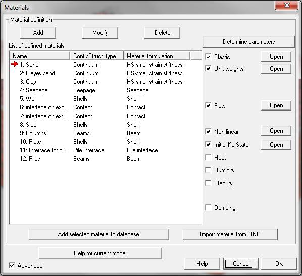
17 Materials


18 Saving files for all parts Imported data (materials, drivers, existence and load functions) will be used during geometry definition of all parts of the model. Let save current stage into 3 files. Under ZSoil Menu choose File\Save As 1. Save as Internal.inp 2. Save as slabs.inp 3. Save as external.inp 4. Run Preprocessing Last saved file is external.inp so data for this part of the model will generated in the Preprocessing.
19 Definition of external part - overview 1. Lines 2. Continuum 2D subdomain with virtual mesh 3. Extrude 2D subdomains to 3D subdomains 4. Delete one internal subdomain
 create construction lines using the toolbar, or top menu Settings/Construction")
20 Definition of external part Create construction lines To speedup drawing of the model (especially in 3D) create construction lines using the toolbar, or top menu Settings/Construction lines.


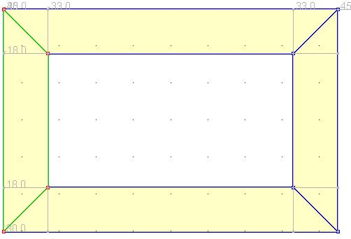
21 Create construction lines Delete all (clik on position column in order to select all elements and press Delete button) Add characteristic X coordinates: -95, -60, 60, 9, Delete all Add characteristic Y coordinate: 0 Delete all Add characteristic Z coordinates: -80, -45, 45, 80
22 Create two rectangles 1. Draw an external rectangle 2. Draw an internal rectangle


23 Create lines 3. Turn off Continue 4. Draw four remaining segments lines connecting external rectangle with internal one
24 Create Continuum 2D inside contour 1. Set XZ projection 2D continuum subdomains will be created through method 2D continuum in contour by picking the point within the closed contour. It is important to set proper project to avoid ambiguity during picking internal point.

25 Create Continuum 2D inside contour 2. Macro Model\Subdomain\ 2D Continuum inside contour 3. Pick 5 times to create 5 subdomains


26 Create virtual mesh 1. Macro Model\Subdomain\ Create virtual mesh 2. Pick internal Subdomain 3. Set Split 10 for Edge 1-2 and for edge Press button Create virtual mesh!

27 Create virtual mesh 5. Pick one of external Subdomain 6. Set Split for Edge 1-4, split for edge 1-2 will be inherited from internal subdomian, which defines split for common edge 7. Press button Create virtual mesh Split for this edge is defined by split adjustment to existing meshed Subdomains

28 Create virtual mesh 8. Pick next external Subdomain 9. Press button Create virtual mesh 10.Repeat steps for next two ramaining subdomains Split for both edges is defined by split adjustment to existing meshed Subdomains
29 Create Continuum 3D by faces extrusion 1. Set 3D view 2. Select faces in zoom box
30 Create Continuum 3D by faces extrusion 3. Macro Model\Subdomain\ 3D Continuum\ 3D Continuum by Face(s) extrusion

31 Create Continuum 3D by faces extrusion 4. Set vector 6. Define parameters for multiple extrusion and press OK 7. Apply 5. Check multiple extrusion
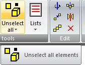
32 Delete Continuum 2D subdomains 1. Hide Continuum 3D subdomains 2. CTRL-A select all 3. Delete from menu SUBDOMAIN => Continuum 2D subdomains will be deleted 4. Show Continuum 3D subdomains
33 Remove top Continuum 3D subdomain 1. Macro Model\Subdomain\ Delete or icon Delete 2. Pick Subdomain


34 Definition of Seepage elements 1. Set orthogonal cameraortogonalną 2. Set XY view 3. Set cursor in Select faces in zoom box mode 4. Select top faces 5. Macro Model\ Seepage\On Subdomain face(s)


 5.")
35 Seepage 1. Unselect all 2. Set XZ view 3. Set cursor in Select faces in zoom box mode 4. Select external faces (4 x zoom box) 5. Macro Model\ Seepage\On Subdomain face(s)

36 Pressure BC 1. Macro Model\ Pressure BC\Fluid head on selected faces
37 Definition of external part is completed FILE\Save model and return to Main Menu Ignore warnings and exit application Save file in ZSoil menu =>File/Save

38 Definition of internal part In ZSoil menu Open Internal.inp Run Preprocessing Create construction lines


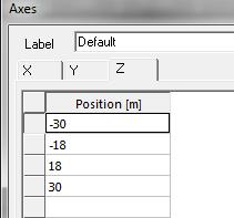
39 Create construction lines Delete all Add characteristic X coordinates: -60, -45, 45, 60 Delete all Add characteristic Y coordinate: 0 Delete all Add characteristic Z coordinates: -45, -30, 30, 45,

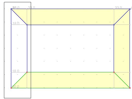
40 Create rectangles Draw 3 rectangles

41 Create Continuum 2D inside contour 1. Set XZ projection 2. Macro Model\Subdomain\ 2D Continuum inside contour 3. Pick 9 times to create 9 subdomains

42 Create virtual mesh 1. Macro Model\Subdomain\ Create virtual mesh 2. Pick internal Subdomain 3. Set Split 30 for Edge 1-2 and Press button Create virtual mesh

43 Create virtual mesh 5. Select corner SubdomainSubdomenę 6. Set split 6 for both edges 7. Create virtual mesh

44 Create virtual mesh Split 6 Split 6 Split 36 Split 6 Split 24 Split 6
45 Create Continuum 3D by faces extrusion 1. Set 3D view 2. Select faces in zoom box
46 Create Continuum 3D by faces extrusion 3. Macro Model\Subdomain\ 3D Continuum\ 3D Continuum by Face(s) extrusion

47 Create Continuum 3D by faces extrusion 4. Set vector 6. Define parameters for multiple extrusion and press OK 7. Apply 5. Check multiple extrusion
48 Delete Continuum 2D subdomains 1. Hide Continuum 3D subdomains 2. CTRL-A select all 3. Delete from menu SUBDOMAIN => Continuum 2D subdomains will be deleted 4. Show Continuum 3D subdomains


49 Setting parameters for excavated elements 1. Change to display Existence Function distribution 2. Define existence function and unloading function Macro Model\Subdomain\ Parameters
50 Setting parameters for excavated elements 1. Set cursor mode to Standard selection mode 2. Pick top internal subdomain 3. Hide selected elements Top subdomain has to be hidden in order to have acces to subdomain below
51 Setting parameters for excavated elements 1. Define existence function and unloading function Macro Model\Subdomain\ Parameters
52 Setting parameters for excavated elements 1. Set cursor mode to Standard selection mode 2. Pick top internal subdomain 3. Hide selected elements Top subdomain has to be hidden in order to have acces to subdomain below
53 Setting parameters for excavated elements 1. Define existence function and unloading function Macro Model\Subdomain\ Parameters
54 Setting parameters for excavated elements 1. Set cursor mode to Standard selection mode 2. Pick top internal subdomain 3. Hide selected elements
55 Setting parameters for excavated elements 1. Define existence function and unloading function Macro Model\Subdomain\ Parameters
56 Definition of the plate 1. Set cursor mode to Standard selection mode 2. Pick second internal subdomain 3. Hide selected elements

57 Plate 1. Macro Model\Subdomain\ 3D shell\3d shell on face(s)
58 Definition of the diaphragm wall These subdomains should be hidden Foundation plate 14 m 1 m Current state of the model Continuum 3D subdomain Model after hidding subdomains Definition of subdomains for diaphragm walls requires hidding foundation plate and continuum 3D subdomain below the plate
59 Definition of the diaphragm wall 1. Set cursor mode to Standard selection mode 2. Pick shell element 3. Hide selected elements 4. Pick 3rd subdomain 5. Hide selected elements


60 Definition of the diaphragm wall 1. Set cursor mode to Select faces with mouse mode 2. Select faces 3. Select Viewing mode to change camera orientation 4. Return to Select faces with mouse mode 5. Select faces


61 Definition of the diaphragm wall 3. Macro Model\Subdomain\ 3D shell\3d shell on face(s)

 5.")
62 Definition of Interface elements on the wall 1. Open dialog box for Subdomain selection 4. Select elements 3. Replace selection 2. Select material number 5 (wall) 5. Close dialog box


63 Show selected element Macro Model\Interface\On Structural Subdomain(s)

64 Positive side => side with external normal Internal Interface is on positive side in this case

65 Why is it worth to define different material number for external and internal interface elements?


66 Why is it worth to define different material number for external and internal interface elements - POSTPROCESSING Maps in postprocessing for interface elements are overlapped. MAP FOR INTERFACE ELEMENTS MAPS ARE OVERLAPPED


67 Select elements with material number 20 With material number required interface element can be selected easily

68 Once selected elements are hidden map is displayed for one layer of elements

69 Definition of Seepage elements 1. Restore hidden elemens 2. Set cursor mode to Standard selection mode 3. Select top external faces 4. Macro Model\ Seepage\On Subdomain face(s)
 7.")
70 Definition of Seepage elements 5. Unselect all faces 6. Macro Model\ Seepage\On Subdomain face(s) 7. Pick top face


71 Definition of Seepage elements under first excavated layer 1. Set cursor mode to Standard selection mode 2. Pick top subdomain 4. Hide selected elements 3. Pick top subdomain 4. Hide selected elements
72 Seepage first stage 1. Macro Model\ Seepage\On Subdomain face(s) 2. Pick top subdomain


73 Seepage second stage 1. Hide interface elements 2. Set cursor mode to Standard selection mode 3. Pick top seepage element 4. Hide selected elements 5. Pick top subdomain 6. Hide selected elements 7. Macro Model\Seepage\On Subdomain face(s) 8. Pick top face

74 Seepage third stage 1. Set cursor mode to Standard selection mode 2. Pick top seepage element 3. Hide selected elements 4. Pick top subdomain 5. Hide selected elements 6. Macro Model\Seepage\On Subdomain face(s) 7. Pick top face
 7. Pick top face")
75 Seepage 4 th stage 1. Set cursor mode to Standard selection mode 2. Pick top seepage element 3. Hide selected elements 4. Pick top subdomain 5. Hide selected elements 6. Hide shells 7. Macro Model\ Seepage\On Subdomain face(s) 7. Pick top face

76 Check excavation stages Definition of internal part is completed FILE\Save model and return to Main Menu with saving changes Ignore warnings and exit application Save file in ZSoil menu =>File/Save
77 Practical modeling of diaphragm walls and foundation rafts with piles part II


78 Slabs In ZSoil menu Open slabs.inp Run Preprocessing Create construction lines

79 1. Draw two rectangles 2. Draw 4 lines 3. Set XZ view 4. Set REPLACE selection mode 5. Set selection in Zoom box 6. Select 4 lines 6. Macro Model\Subdomain\Shell\3D Shell On Contour

80 1. Select 4 lines 2. Macro Model\Subdomain\Shell\3D Shell On Contour


81 Create virtual mesh split 4 split 36 split 24 split Set 3D view 2. Change direction for shell (if necessary) Macro Model\Subdomain\Reverse direction split 36
82 Parameters 1. Set selection in Zoom box 2. Select all shells 3. Macro Model\Subdomain\Parameters


83 1. Unselect all 2. Hide shell subdomains 3. Create beam FE Model\Beam\Enter XYZ for 2 points 4. Set parameters for beam FE Model\Beam\Parameters
84 1. Copy beam with translation FE Model\Beam\ Copy with translation

85 1. Set orthogonal camera 2. Set XZ view 3. Select beams in zoom box 4. Copy selected beams FE Model\Beam\Copy with translation 5. Unselect all
86 1. Change view 2. Move beam FE Model\Beam\Move 1. Change view 2. Move beam FE Model\Beam\Move


87 1. Select all Beams 2. Create auxiliary plane 2. Copy beam by symmetry 3. FE Model\Beam\Copy by symmetry
88 1. Unselect all 2. Set cursor in Standard selection mode 3. Select two beams 4. Copy selected beams FE Model\Beam\Copy with translation
89 1. Set XZ view 2. Set REPLACE selection mode 3. Set selection in Zoom box mode 4. Select one row of beams on left side 5. Copy selected beams FE Model\Beam\Copy with translation
90 1. Set selection in Zoom box mode 2. Select one row of beams on right side 3. Copy selected beams Model\Beam\Copy with translation


91 Copy columns and slabs 1. Show shell subdomains 2. Select all beams 3. Select all subdomains 4. Copy selected elements
92 Columns extension by 1 m up to level -15 m 1. Set orthogonal camera 2. Set XY view 3. Unselect all elements 4. Set selection in Zoom box mode 5. Select nodes in zoom box
93 Columns extension by 1 m up to level -15 m 1. FE Model\Node\Move

94 Set existence function for the slabs 1. Set Replace selection mode 2. Set selection in Zoom box 3. Select top slab 4. Macro ModeSubdomain\Parameters

95 Set existence function for the slabs 1. Select second slab 2. Macro ModeSubdomain\Parameters 3. Select third slab 4. Macro ModeSubdomain\Parameters
96 Piles under temporary columns 1. Creat lines by selected NODES extrusion Macro Model\Objects\Line\By Node(s) extrusion
97 Piles under building Set XZ view


98 Piles under building 1. Create point: Macro Model\Point\Point 2. Copy point: Macro Model\Point\Copy \Copy with translation


99 Piles under building 1. Select points in Zoom Box 2. Copy points: Macro Model\Point\Copy \Copy with translation


100 Piles under building 1. Select points in Zoom Box 2. Creat lines by selected POINTS extrusion: Macro Model\Objects\Line\By Point(s) extrusion

101 Piles on selected objects 1. Set orthogonal camera 2. Set XY view 3. Unselect all elements 4. Set selection in Zoom box 5. Select lines dragging from rigth to left

102 Piles on selected objects 1. Macro Model\Pile\On object(s)

103 Set parameters for piles under building Set XZ view 1. Select elements in Zoom box 2. Macro Model\Pile\Parameters


104 Create real mesh 1. CTRL-A 2. Macro Model\Subdomain\Vistrual->Real mesh 3. Unselect all 4. Set 3D view 5. Hide local bases for shells


105 Linking columns with slabs 1. Select all beams 2. Select all nodes which belong to beams 3. Select all shells one layer


106 Linking columns with slabs 1. Show selected elements 2. Set XY view 3. Unselet all elements 4. Set selection in Zoom box mode

107 Linking columns with slabs 1. Select top nodes and shells 2. FE Model\Nodal link On node(s) 3. Unselet all elements

108 Linking columns with slabs 1. Set selection in Zoom box and select next nodes and shells 2. FE Model\Nodal link On node(s) 3. Unselet all elements

109 Linking columns with slabs 1. Set selection in Zoom box and select next nodes and shells 2. FE Model\Nodal link On node(s) 3. Unselet all elements


110 Check construction stages 1. Set 3D view 2. Set Show excavation/construction stages mode Save model and return Main Menu
 internal.")
111 Merging defined parts 1. Open External.inp in Zsoil Menu 2. Save as Wall3D.inp 3. Run preprocessing 4. File\Import geometrical model (*.inp) internal.inp


112 Surface load definition 1. Hide seepage 2. Select subdomain Faces 3. Macro Model\Surface Load\On Face(s) (Uniform)


113 Create Real mesh Select All (CTRL-A) Macro Model\Subdomain\Virtual -> Real mesh Hide objects 4. Unselect all


114 Create Nodal links 1. Select nodes with Inconsisten split


115 Create Nodal links 1. Set orthogonal camera 2. Set XZ view 3. Select Continuum 3D in zoom box : FE Model\Continnum 3D\In zoom box SELECTION BY ZOOM BOX FROM RIGHT TO LEFT (CROSSING)


116 Create Nodal links 1. Set XY view 2. Select Continuum 3D in zoom box : 3. Select Nodes from selected elements BRICK (B8) subtract from selection


")
117 Create Nodal links FE Model\Nodal link\ On node(s) Unselect all
118 Merging step 2 File\Import geometrical model (*.inp) -> slabs.inp


119 Link Pile Head 1. Unselect all 2. Select shells with material Select all piles 4. Select all beams 5. Show selected elements


120 Link Pile Head 6. Macro Model\Piles\ Link Pile head

121 Import nodal loads from external file FE Model\Loads\Noda load\import


122 Link nodes with nodal load with plate 1. Show hidden nodes 2. Select nodes with nodal load

123 Link nodes with nodal load with plate FE Model\Nodal link\ On node(s)
124 Create boreholes Domain\Boreholes\From dialog 1. Press New 2. Enter Label 3. Enter coordinates 4. Enter data for layers 5. Press Add

125 Borehole 2 1. Press New 2. Enter Label 3. Enter coordinates 4. Enter data for layers 5. Press Add
126 Borehole 3 1. Press New 2. Enter Label 3. Enter coordinates 4. Enter data for layers 5. Press Add

127 Borehole 3 1. Enter data 2. Close dialog box


128 Domain\Boreholes\Map material on visible elements Select and show Continuum 3D elements with material 1 Results of material mapping can be checked by selection Continuum 3D elements with Initial material and displaying selected elements

129 Initial stresses FE Model\Initial Conditions\Initial stresses\on bounding box


130 Initial stresses
131 Solid BC FE Model\Boundary Conditions\Solid BC On box FILE\Save model and return to Main Menu with saving changes


 Check excavation stages")
132 Linking bottom part of the wall with soil 1. Click line in order to select nodes 2. Press Return to the application 3. FE Model\Interface\Link Interface node(s) Check excavation stages FILE\Save model and return to Main Menu
133 Drivers c v E 2 oed k m d = = γ F kn m h t γ c = = 0.26 [ d] θc v 10 kn 3 m = m d 2
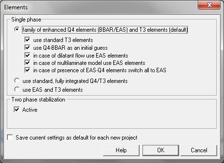
134 Two phase stabilization
FOUNDATION IN OVERCONSOLIDATED CLAY
 1 FOUNDATION IN OVERCONSOLIDATED CLAY In this chapter a first application of PLAXIS 3D is considered, namely the settlement of a foundation in clay. This is the first step in becoming familiar with the
Nailing of a slope. c ZACE Services Ltd. August / 38 2 / 38
 Nailing of a slope c ZACE Services Ltd August 2011 1 / 38 2 / 38 3D draft Y 12m X 13m 13m 10m 15m 15m 10m 15m 10m Z 3 / 38 1 We want to generate a model of a nailed slope with the given geometry 2 This
PLAXIS 3D. Tutorial Manual
 PLAXIS 3D Tutorial Manual 2010 Build 2681 TABLE OF CONTENTS TABLE OF CONTENTS 1 Introduction 5 2 Lesson 1: Foundation in overconsolidated clay 7 2.1 Geometry 7 2.2 Case A: Rigid foundation 8 2.3 Case B:
PLAXIS 3D. Tutorial Manual
 PLAXIS 3D Tutorial Manual 2017 Build 9039 TABLE OF CONTENTS TABLE OF CONTENTS 1 Foundation in overconsolidated clay 7 1.1 Case A: Rigid foundation 8 1.2 Case B: Raft foundation 20 1.3 Case C: Pile-Raft
SETTLEMENT OF A CIRCULAR FOOTING ON SAND
 1 SETTLEMENT OF A CIRCULAR FOOTING ON SAND In this chapter a first application is considered, namely the settlement of a circular foundation footing on sand. This is the first step in becoming familiar
TABLE OF CONTENTS WHAT IS ADVANCE DESIGN? INSTALLING ADVANCE DESIGN... 8 System requirements... 8 Advance Design installation...
 Starting Guide 2019 TABLE OF CONTENTS INTRODUCTION... 5 Welcome to Advance Design... 5 About this guide... 6 Where to find information?... 6 Contacting technical support... 6 WHAT IS ADVANCE DESIGN?...
Advance Design. Tutorial
 TUTORIAL 2018 Advance Design Tutorial Table of Contents About this tutorial... 1 How to use this guide... 3 Lesson 1: Preparing and organizing your model... 4 Step 1: Start Advance Design... 5 Step 2:
DRY EXCAVATION USING A TIE BACK WALL
 3 This example involves the dry construction of an excavation. The excavation is supported by concrete diaphragm walls. The walls are tied back by prestressed ground anchors. Silt Sand 10 m 2 m 20 m 10
Case Study 1: Piezoelectric Rectangular Plate
 Case Study 1: Piezoelectric Rectangular Plate PROBLEM - 3D Rectangular Plate, k31 Mode, PZT4, 40mm x 6mm x 1mm GOAL Evaluate the operation of a piezoelectric rectangular plate having electrodes in the
PHASED EXCAVATION OF A SHIELD TUNNEL
 5 PHASED EXCAVATION OF A SHIELD TUNNEL The lining of a shield tunnel is often constructed using prefabricated concrete ring segments, which are bolted together within the tunnel boring machine to form
Introduction: RS 3 Tutorial 1 Quick Start
 Introduction: RS 3 Tutorial 1 Quick Start Welcome to RS 3. This tutorial introduces some basic features of RS 3. The model analyzes the effect of tank loading on an existing sloped underground tunnel.
Creating and Analyzing a Simple Model in Abaqus/CAE
 Appendix B: Creating and Analyzing a Simple Model in Abaqus/CAE The following section is a basic tutorial for the experienced Abaqus user. It leads you through the Abaqus/CAE modeling process by visiting
GTS NX INTERFACES AUTOCAD MIDAS GEN FOR TUNNEL SOIL PILE INTERACTION ANALYSIS
 INTERFACES AUTOCAD MIDAS GEN FOR TUNNEL SOIL PILE INTERACTION ANALYSIS Angel F. Martinez Civil Engineer MIDASOFT Integrated Solver Optimized for the next generation 64-bit platform Finite Element Solutions
PLAXIS 2D - SUBMERGED CONSTRUCTION OF AN EXCAVATION
 PLAXIS 2D - SUBMERGED CONSTRUCTION OF AN EXCAVATION 3 SUBMERGED CONSTRUCTION OF AN EXCAVATION This tutorial illustrates the use of PLAXIS for the analysis of submerged construction of an excavation. Most
Appendix B: Creating and Analyzing a Simple Model in Abaqus/CAE
 Getting Started with Abaqus: Interactive Edition Appendix B: Creating and Analyzing a Simple Model in Abaqus/CAE The following section is a basic tutorial for the experienced Abaqus user. It leads you
Lateral Loading of Suction Pile in 3D
 Lateral Loading of Suction Pile in 3D Buoy Chain Sea Bed Suction Pile Integrated Solver Optimized for the next generation 64-bit platform Finite Element Solutions for Geotechnical Engineering 00 Overview
SUBMERGED CONSTRUCTION OF AN EXCAVATION
 2 SUBMERGED CONSTRUCTION OF AN EXCAVATION This tutorial illustrates the use of PLAXIS for the analysis of submerged construction of an excavation. Most of the program features that were used in Tutorial
Finite Element Analysis Using NEi Nastran
 Appendix B Finite Element Analysis Using NEi Nastran B.1 INTRODUCTION NEi Nastran is engineering analysis and simulation software developed by Noran Engineering, Inc. NEi Nastran is a general purpose finite
3D Soil Modelling (Geometry)
") 3D Soil Modelling (Geometry) Soil Profiling1 Description: This step shows how to import bolehole log data from a spreadsheet into GTS in preparation of soil modelling. Step 1. 1. Open GTS.exe 2. Main Menu:
3D Soil Modelling (Geometry) Soil Profiling1 Description: This step shows how to import bolehole log data from a spreadsheet into GTS in preparation of soil modelling. Step 1. 1. Open GTS.exe 2. Main Menu:
PLAXIS 2D. Tutorial Manual
 PLAXIS 2D Tutorial Manual 2017 Build 8601 TABLE OF CONTENTS TABLE OF CONTENTS 1 Settlement of a circular footing on sand 7 1.1 Geometry 7 1.2 Case A: Rigid footing 8 1.3 Case B: Flexible footing 23 2 Submerged
v GMS 10.0 Tutorial UTEXAS Dam with Seepage Use SEEP2D and UTEXAS to model seepage and slope stability of an earth dam
 v. 10.0 GMS 10.0 Tutorial Use SEEP2D and UTEXAS to model seepage and slope stability of an earth dam Objectives Learn how to build an integrated SEEP2D/UTEXAS model in GMS. Prerequisite Tutorials SEEP2D
v. 9.0 GMS 9.0 Tutorial UTEXAS Dam with Seepage Use SEEP2D and UTEXAS to model seepage and slope stability of a earth dam Prerequisite Tutorials None
 v. 9.0 GMS 9.0 Tutorial Use SEEP2D and UTEXAS to model seepage and slope stability of a earth dam Objectives Learn how to build an integrated SEEP2D/UTEXAS model in GMS. Prerequisite Tutorials None Required
Quarter Symmetry Tank Stress (Draft 4 Oct 24 06)
") Quarter Symmetry Tank Stress (Draft 4 Oct 24 06) Introduction You need to carry out the stress analysis of an outdoor water tank. Since it has quarter symmetry you start by building only one-fourth of
Quarter Symmetry Tank Stress (Draft 4 Oct 24 06) Introduction You need to carry out the stress analysis of an outdoor water tank. Since it has quarter symmetry you start by building only one-fourth of
Start AxisVM by double-clicking the AxisVM icon in the AxisVM folder, found on the Desktop, or in the Start, Programs Menu.
 4. MEMBRANE MODEL 1.1. Preprocessing with surface elements Start New Start AxisVM by double-clicking the AxisVM icon in the AxisVM folder, found on the Desktop, or in the Start, Programs Menu. Create a
5. Shell Reinforcement According To Eurocode 2
 5. Shell Reinforcement According To Eurocode Applicable CivilFEM Product: All CivilFEM Products Level of Difficulty: Moderate Interactive Time Required: 5 minutes Discipline: Concrete Shell Reinforcement
Torsional-lateral buckling large displacement analysis with a simple beam using Abaqus 6.10
 Torsional-lateral buckling large displacement analysis with a simple beam using Abaqus 6.10 This document contains an Abaqus tutorial for performing a buckling analysis using the finite element program
Case Study 2: Piezoelectric Circular Plate
 Case Study 2: Piezoelectric Circular Plate PROBLEM - 3D Circular Plate, kp Mode, PZT4, D=50mm x h=1mm GOAL Evaluate the operation of a piezoelectric circular plate having electrodes in the top and bottom
Lesson: Static Stress Analysis of a Connecting Rod Assembly
 Lesson: Static Stress Analysis of a Connecting Rod Assembly In this tutorial we determine the effects of a 2,000 pound tensile load acting on a connecting rod assembly (consisting of the rod and two pins).
PLAXIS 3D FOUNDATION Reference Manual Version 2
 PLAXIS 3D FOUNDATION Reference Manual Version 2 TABLE OF CONTENTS TABLE OF CONTENTS 1 Introduction...1-1 2 General information...2-1 2.1 Units and sign conventions...2-1 2.2 File handling...2-3 2.2.1
Kratos Multi-Physics 3D Fluid Analysis Tutorial. Pooyan Dadvand Jordi Cotela Kratos Team
 Kratos Multi-Physics 3D Fluid Analysis Tutorial Pooyan Dadvand Jordi Cotela Kratos Team Kratos 3D Fluid Tutorial In this tutorial we will solve a simple example using GiD and Kratos Geometry Input data
CE Advanced Structural Analysis. Lab 4 SAP2000 Plane Elasticity
 Department of Civil & Geological Engineering COLLEGE OF ENGINEERING CE 463.3 Advanced Structural Analysis Lab 4 SAP2000 Plane Elasticity February 27 th, 2013 T.A: Ouafi Saha Professor: M. Boulfiza 1. Rectangular
Abaqus/CAE (ver. 6.10) Stringer Tutorial
 Stringer Tutorial") Abaqus/CAE (ver. 6.10) Stringer Tutorial Problem Description A table made of steel tubing with a solid steel top and shelf is loaded with an oblique impulse load. Determine the transient response of the
Abaqus/CAE (ver. 6.10) Stringer Tutorial Problem Description A table made of steel tubing with a solid steel top and shelf is loaded with an oblique impulse load. Determine the transient response of the
Basic Modeling 1 Tekla Structures 12.0 Basic Training September 19, 2006
 Tekla Structures 12.0 Basic Training September 19, 2006 Copyright 2006 Tekla Corporation Contents Contents 3 1 5 1.1 Start Tekla Structures 6 1.2 Create a New Model BasicModel1 7 1.3 Create Grids 10 1.4
Exercise 1. 3-Point Bending Using the GUI and the Bottom-up-Method
 Exercise 1 3-Point Bending Using the GUI and the Bottom-up-Method Contents Learn how to... 1 Given... 2 Questions... 2 Taking advantage of symmetries... 2 A. Preprocessor (Setting up the Model)... 3 A.1
Large scale modeling and simulations with ZSOIL
 Large scale modeling and simulations with ZSOIL c ZACE Services Ltd January 2017 1 / 79 Contents Tackling the large scale modeling and simulations Hardware requirements Getting started Pre-Processing -
Modeling Foundations in RS
 Modeling Foundations in RS 3 Piled Raft Modeling in RS 3 Deep foundation piles are commonly used to increase foundation stability and to increase the bearing capacity of structural systems. The design
Revised Iain A MacLeod
 LUSAS User Guidelines Revised 01.07.15 Iain A MacLeod Contents 1 Geometrical features and meshes... 1 2 Toolbars... 2 3 Inserting points... 2 4 Inserting a line between two points... 2 5 Creating a dataset...
v GMS 10.0 Tutorial SEEP2D Sheet Pile Use SEEP2D to create a flow net around a sheet pile Prerequisite Tutorials Feature Objects
 v. 10.0 GMS 10.0 Tutorial Use SEEP2D to create a flow net around a sheet pile Objectives Learn how to set up and solve a seepage problem involving flow around a sheet pile using the SEEP2D interface in
Static Stress Analysis
 Static Stress Analysis Determine stresses and displacements in a connecting rod assembly. Lesson: Static Stress Analysis of a Connecting Rod Assembly In this tutorial we determine the effects of a 2,000-pound
PLAXIS 3D FOUNDATION. Tutorial Manual version 1.5
 PLAXIS 3D FOUNDATION Tutorial Manual version 1.5 TABLE OF CONTENTS TABLE OF CONTENTS 1 Introduction...1-1 2 Getting started...2-1 2.1 Installation...2-1 2.2 General modelling aspects...2-1 2.3 Input procedures...2-3
v SEEP2D Sheet Pile Use SEEP2D to create a flow net around a sheet pile GMS Tutorials Time minutes Prerequisite Tutorials Feature Objects
 v. 10.1 GMS 10.1 Tutorial Use SEEP2D to create a flow net around a sheet pile Objectives Learn how to set up and solve a seepage problem involving flow around a sheet pile using the SEEP2D interface in
v. 9.0 GMS 9.0 Tutorial SEEP2D Sheet Pile Use SEEP2D to create a flow net around a sheet pile Prerequisite Tutorials None Time minutes
 v. 9.0 GMS 9.0 Tutorial Use SEEP2D to create a flow net around a sheet pile Objectives Learn how to set up and solve a seepage problem involving flow around a sheet pile using the SEEP2D interface in GMS.
FINITE ELEMENT ANALYSIS OF A PLANAR TRUSS
 Problem Description: FINITE ELEMENT ANALYSIS OF A PLANAR TRUSS Instructor: Professor James Sherwood Revised: Dimitri Soteropoulos Programs Utilized: Abaqus/CAE 6.11-2 This tutorial explains how to build
3 SETTLEMENT OF A CIRCULAR FOOTING ON SAND (LESSON 1) Figure 3.1 Geometry of a circular footing on a sand layer
 Figure 3.1 Geometry of a circular footing on a sand layer") SETTLEMENT OF A CIRCULAR FOOTING ON SAND (LESSON 1) 3 SETTLEMENT OF A CIRCULAR FOOTING ON SAND (LESSON 1) In the previous chapter some general aspects and basic features of the PLAXIS program were presented.
SETTLEMENT OF A CIRCULAR FOOTING ON SAND (LESSON 1) 3 SETTLEMENT OF A CIRCULAR FOOTING ON SAND (LESSON 1) In the previous chapter some general aspects and basic features of the PLAXIS program were presented.
General Information Project management Introduction... 4 Getting Started Input geometry... 7
 Tutorial Shell Tutorial Shell All information in this document is subject to modification without prior notice. No part or this manual may be reproduced, stored in a database or retrieval system or published,
Example Plate with a hole
 Course in ANSYS Example Plate with a hole A Objective: Determine the maximum stress in the x-direction for point A and display the deformation figure Tasks: Create a submodel to increase the accuracy of
Important Note - Please Read:
 Important Note - Please Read: This tutorial requires version 6.01 or later of SAFE to run successfully. You can determine what version of SAFE you have by starting the program and then clicking the Help
Custom Components for Precast Concrete Tekla Structures 12.0 Basic Training September 19, 2006
 Custom Components for Precast Concrete Tekla Structures 12.0 Basic Training September 19, 2006 Copyright 2006 Tekla Corporation Contents Contents...i 4...3 4.1 Define Custom Part of Fastener Plate...3
Tekla Structures Analysis Guide. Product version 21.0 March Tekla Corporation
 Tekla Structures Analysis Guide Product version 21.0 March 2015 2015 Tekla Corporation Contents 1 Getting started with analysis... 7 1.1 What is an analysis model... 7 Analysis model objects...9 1.2 About
ANSYS 5.6 Tutorials Lecture # 2 - Static Structural Analysis
 R50 ANSYS 5.6 Tutorials Lecture # 2 - Static Structural Analysis Example 1 Static Analysis of a Bracket 1. Problem Description: The objective of the problem is to demonstrate the basic ANSYS procedures
3 AXIS STANDARD CAD. BobCAD-CAM Version 28 Training Workbook 3 Axis Standard CAD
 3 AXIS STANDARD CAD This tutorial explains how to create the CAD model for the Mill 3 Axis Standard demonstration file. The design process includes using the Shape Library and other wireframe functions
ECE421: Electronics for Instrumentation
 ECE421: Electronics for Instrumentation Lecture #8: Introduction to FEA & ANSYS Mostafa Soliman, Ph.D. March 23 rd 2015 Mostafa Soliman, Ph.D. 1 Outline Introduction to Finite Element Analysis Introduction
Lecture # 5 Modal or Dynamic Analysis of an Airplane Wing
 Lecture # 5 Modal or Dynamic Analysis of an Airplane Wing Problem Description This is a simple modal analysis of a wing of a model airplane. The wing is of uniform configuration along its length and its
Autodesk Inventor 2019 and Engineering Graphics
 Autodesk Inventor 2019 and Engineering Graphics An Integrated Approach Randy H. Shih SDC PUBLICATIONS Better Textbooks. Lower Prices. www.sdcpublications.com Powered by TCPDF (www.tcpdf.org) Visit the
Abaqus/CAE Heat Transfer Tutorial
 Abaqus/CAE Heat Transfer Tutorial Problem Description The thin L shaped steel part shown above (lengths in meters) is exposed to a temperature of 20 o C on the two surfaces of the inner corner, and 120
RFEM 5. Spatial Models Calculated acc. to Finite Element Method. Dlubal Software GmbH Am Zellweg 2 D Tiefenbach
 Version July 2013 Program RFEM 5 Spatial Models Calculated acc. to Finite Element Method Tutorial All rights, including those of translations, are reserved. No portion of this book may be reproduced mechanically,
Start AxisVM by double-clicking the AxisVM icon in the AxisVM folder, found on the Desktop, or in the Start, Programs Menu.
 1. BEAM MODEL Start New Start AxisVM by double-clicking the AxisVM icon in the AxisVM folder, found on the Desktop, or in the Start, Programs Menu. Create a new model with the New Icon. In the dialogue
GTS. midas GTS Advanced Webinar. Date: June 5, 2012 Topic: General Use of midas GTS (Part II) Presenter: Vipul Kumar
 Presenter: Vipul Kumar") midas GTS Advanced Webinar Date: June 5, 2012 Topic: General Use of midas GTS (Part II) Presenter: Vipul Kumar Bridging Your Innovations to Realities GTS MIDAS Information Technology Co., Ltd. [1/30] Contents:
midas GTS Advanced Webinar Date: June 5, 2012 Topic: General Use of midas GTS (Part II) Presenter: Vipul Kumar Bridging Your Innovations to Realities GTS MIDAS Information Technology Co., Ltd. [1/30] Contents:
Tutorial. Spring Foundation
 Page i Preface This tutorial provides an example on how to model a spring foundation using BRIGADE/Plus. Page ii Contents 1 OVERVIEW... 1 2 GEOMETRY... 1 3 MATERIAL AND SECTION PROPERTIES... 2 4 STEP DEFINITION...
Revised Iain A MacLeod
 LUSAS User Guidelines Revised 20.06.14 Iain A MacLeod Contents 1 Geometrical features and meshes... 1 2 Toolbars... 1 3 Inserting points... 1 4 Inserting a line between two points... 1 5 Creating a dataset...
Learning Module 8 Shape Optimization
 Learning Module 8 Shape Optimization What is a Learning Module? Title Page Guide A Learning Module (LM) is a structured, concise, and self-sufficient learning resource. An LM provides the learner with
Installation Guide. Beginners guide to structural analysis
 Installation Guide To install Abaqus, students at the School of Civil Engineering, Sohngaardsholmsvej 57, should log on to \\studserver, whereas the staff at the Department of Civil Engineering should
Lesson 1 Parametric Modeling Fundamentals
 1-1 Lesson 1 Parametric Modeling Fundamentals Create Simple Parametric Models. Understand the Basic Parametric Modeling Process. Create and Profile Rough Sketches. Understand the "Shape before size" approach.
Multiframe Oct 2008
 Multiframe 11.01 3 Oct 2008 Windows Release Note This release note describes the Windows version 11.01 of Multiframe, Steel Designer and Section Maker. This release will run on Windows XP/2003/Vista/2008.
Settlement Analysis of a Strip Footing Linear Static Analysis (Benchmark Example)
") Settlement Analysis of a Strip Footing Linear Static Analysis (Benchmark Example) analys: linear static. constr: suppor. elemen: ct12e pstrai. load: edge elemen force. materi: elasti isotro porosi. option:
Settlement Analysis of a Strip Footing Linear Static Analysis (Benchmark Example) analys: linear static. constr: suppor. elemen: ct12e pstrai. load: edge elemen force. materi: elasti isotro porosi. option:
Workbench Tutorial Minor Losses, Page 1 Tutorial Minor Losses using Pointwise and FLUENT
 Workbench Tutorial Minor Losses, Page 1 Tutorial Minor Losses using Pointwise and FLUENT Introduction This tutorial provides instructions for meshing two internal flows. Pointwise software will be used
ME 442. Marc/Mentat-2011 Tutorial-1
 ME 442 Overview Marc/Mentat-2011 Tutorial-1 The purpose of this tutorial is to introduce the new user to the MSC/MARC/MENTAT finite element program. It should take about one hour to complete. The MARC/MENTAT
Abaqus/CAE Axisymmetric Tutorial (Version 2016)
") Abaqus/CAE Axisymmetric Tutorial (Version 2016) Problem Description A round bar with tapered diameter has a total load of 1000 N applied to its top face. The bottom of the bar is completely fixed. Determine
Abaqus/CAE Axisymmetric Tutorial (Version 2016) Problem Description A round bar with tapered diameter has a total load of 1000 N applied to its top face. The bottom of the bar is completely fixed. Determine
Exercise Guide. Published: August MecSoft Corpotation
 VisualCAD Exercise Guide Published: August 2018 MecSoft Corpotation Copyright 1998-2018 VisualCAD 2018 Exercise Guide by Mecsoft Corporation User Notes: Contents 2 Table of Contents About this Guide 4
CE366/ME380 Finite Elements in Applied Mechanics I Fall 2007
 CE366/ME380 Finite Elements in Applied Mechanics I Fall 2007 FE Project 1: 2D Plane Stress Analysis of acantilever Beam (Due date =TBD) Figure 1 shows a cantilever beam that is subjected to a concentrated
Analysis Steps 1. Start Abaqus and choose to create a new model database
 Source: Online tutorials for ABAQUS Problem Description The two dimensional bridge structure, which consists of steel T sections (b=0.25, h=0.25, I=0.125, t f =t w =0.05), is simply supported at its lower
Memo Block. This lesson includes the commands Sketch, Extruded Boss/Base, Extruded Cut, Shell, Polygon and Fillet.
 Commands Used New Part This lesson includes the commands Sketch, Extruded Boss/Base, Extruded Cut, Shell, Polygon and Fillet. Click File, New on the standard toolbar. Select Part from the New SolidWorks
ATENA Program Documentation Part 4-2. Tutorial for Program ATENA 3D. Written by: Jan Červenka, Zdenka Procházková, Tereza Sajdlová
 Červenka Consulting s.ro. Na Hrebenkach 55 150 00 Prague Czech Republic Phone: +420 220 610 018 E-mail: cervenka@cervenka.cz Web: http://www.cervenka.cz ATENA Program Documentation Part 4-2 Tutorial for
BioIRC solutions. CFDVasc manual
 BioIRC solutions CFDVasc manual Main window of application is consisted from two parts: toolbar - which consist set of button for accessing variety of present functionalities image area area in which is
Chapter 2. Structural Tutorial
 Chapter 2. Structural Tutorial Tutorials> Chapter 2. Structural Tutorial Static Analysis of a Corner Bracket Problem Specification Problem Description Build Geometry Define Materials Generate Mesh Apply
ANSYS. Geometry. Material Properties. E=2.8E7 psi v=0.3. ansys.fem.ir Written By:Mehdi Heydarzadeh Page 1
 Attention: This tutorial is outdated, you will be redirected automatically to the new site. If you are not redirected, click this link to the confluence site. Problem Specification Geometry Material Properties
Contact Analysis. Learn how to: define surface contact solve a contact analysis display contact results. I-DEAS Tutorials: Simulation Projects
 Contact Analysis I-DEAS Tutorials: Simulation Projects This tutorial shows how to analyze surface contact. The electrical flash contacts in a 35mm camera will be modeled to calculate the contact forces.
Step by Step. Tutorial for AxisVM X4. Edited by: Inter-CAD Kft.
 Step by Step Tutorial for AxisVM X4 Edited by: Inter-CAD Kft. 2018 Inter-CAD Kft. All rights reserved All brand and product names are trademarks or registered trademarks. Intentionally blank page Step
file://c:\documents and Settings\sala\Configuración local\temp\~hha54f.htm
 Página 1 de 26 Tutorials Chapter 2. Structural Tutorial 2.1. Static Analysis of a Corner Bracket 2.1.1. Problem Specification Applicable ANSYS Products: Level of Difficulty: Interactive Time Required:
Autodesk Fusion 360: Model. Overview. Modeling techniques in Fusion 360
 Overview Modeling techniques in Fusion 360 Modeling in Fusion 360 is quite a different experience from how you would model in conventional history-based CAD software. Some users have expressed that it
This document gives a detailed summary of the new features and improvements of FEM- Design version 16.
 This document gives a detailed summary of the new features and improvements of FEM- Design version 16. We hope you will enjoy using the program and its new tools and possibilities. We wish you success.
Version October 2015 RFEM 5. Spatial Models Calculated acc. to Finite Element Method. Introductory Example
 Version October 2015 Program RFEM 5 Spatial Models Calculated acc. to Finite Element Method Introductory Example All rights, including those of translations, are reserved. No portion of this book may be
Concrete Plate Concrete Slab (ACI )
") Tutorial Tutorial Concrete Plate Concrete Slab (ACI 318-08) Tutorial Concrete Plate All information in this document is subject to modification without prior notice. No part or this manual may be reproduced,
Tutorial Tutorial Concrete Plate Concrete Slab (ACI 318-08) Tutorial Concrete Plate All information in this document is subject to modification without prior notice. No part or this manual may be reproduced,
Solidworks 2006 Surface-modeling
 Solidworks 2006 Surface-modeling (Tutorial 2-Mouse) Surface-modeling Solid-modeling A- 1 Assembly Design Design with a Master Model Surface-modeling Tutorial 2A Import 2D outline drawing into Solidworks2006
SAFI Sample Projects. Design of a Steel Structure. SAFI Quality Software Inc. 3393, chemin Sainte-Foy Ste-Foy, Quebec, G1X 1S7 Canada
 SAFI Sample Projects Design of a Steel Structure SAFI Quality Software Inc. 3393, chemin Sainte-Foy Ste-Foy, Quebec, G1X 1S7 Canada Contact: Rachik Elmaraghy, P.Eng., M.A.Sc. Tel.: 1-418-654-9454 1-800-810-9454
Abaqus CAE Tutorial 1: 2D Plane Truss
 ENGI 7706/7934: Finite Element Analysis Abaqus CAE Tutorial 1: 2D Plane Truss Lab TA: Xiaotong Huo EN 3029B xh0381@mun.ca Download link for Abaqus student edition: http://academy.3ds.com/software/simulia/abaqus-student-edition/
RAPID DRAWDOWN ANALYSIS
 RAPID DRAWDOWN ANALYSIS 6 RAPID DRAWDOWN ANALYSIS This example concerns the stability of a reservoir dam under conditions of drawdown. Fast reduction of the reservoir level may lead to instability of the
TUTORIAL 2. OBJECTIVE: Use SolidWorks/COSMOS to model and analyze a cattle gate bracket that is subjected to a force of 100,000 lbs.
 TUTORIAL 2 OBJECTIVE: Use SolidWorks/COSMOS to model and analyze a cattle gate bracket that is subjected to a force of 100,000 lbs. GETTING STARTED: 1. Open the SolidWorks program. 2. Open a new part file.
LAB # 2 3D Modeling, Properties Commands & Attributes
 COMSATS Institute of Information Technology Electrical Engineering Department (Islamabad Campus) LAB # 2 3D Modeling, Properties Commands & Attributes Designed by Syed Muzahir Abbas 1 1. Overview of the
An Introduction to SolidWorks Flow Simulation 2010
 An Introduction to SolidWorks Flow Simulation 2010 John E. Matsson, Ph.D. SDC PUBLICATIONS www.sdcpublications.com Schroff Development Corporation Chapter 2 Flat Plate Boundary Layer Objectives Creating
CECOS University Department of Electrical Engineering. Wave Propagation and Antennas LAB # 1
 CECOS University Department of Electrical Engineering Wave Propagation and Antennas LAB # 1 Introduction to HFSS 3D Modeling, Properties, Commands & Attributes Lab Instructor: Amjad Iqbal 1. What is HFSS?
Table of Contents Memory Management... 3 Results Enveloping... 5 Set Random Property Colors... 8 Model Box Extend Merge Mesh...
 1 Table of Contents Memory Management... 3 Results Enveloping... 5 Set Random Property Colors... 8 Model Box... 11 Extend Merge Mesh... 13 NonManifold Add... 16 Element Visual Inspection... 18 Graphical
PLAXIS 3D Tunnel. Tutorial Manual
 PLAXIS 3D Tunnel Tutorial Manual TABLE OF CONTENTS TABLE OF CONTENTS 1 Introduction...1-1 2 Getting started...2-1 2.1 Installation...2-1 2.2 General modelling aspects...2-1 2.3 Input procedures...2-3
Problem O. Isolated Building - Nonlinear Time History Analysis. Steel E =29000 ksi, Poissons Ratio = 0.3 Beams: W24X55; Columns: W14X90
 Problem O Isolated Building - Nonlinear Time History Analysis Steel E =29000 ksi, Poissons Ratio = 0.3 Beams: W24X55; Columns: W14X90 Rubber Isolator Properties Vertical (axial) stiffness = 10,000 k/in
NX Tutorial - Centroids and Area Moments of Inertia ENAE 324 Aerospace Structures Spring 2015
 NX will automatically calculate area and mass information about any beam cross section you can think of. This tutorial will show you how to display a section s centroid, principal axes, 2 nd moments of
3ds Max Cottage Step 1. Always start out by setting up units: We re going with this setup as we will round everything off to one inch.
 3ds Max Cottage Step 1 Always start out by setting up units: We re going with this setup as we will round everything off to one inch. File/Import the CAD drawing Be sure Files of Type is set to all formats
ABAQUS for CATIA V5 Tutorials
 ABAQUS for CATIA V5 Tutorials AFC V2.5 Nader G. Zamani University of Windsor Shuvra Das University of Detroit Mercy SDC PUBLICATIONS Schroff Development Corporation www.schroff.com ABAQUS for CATIA V5,
Finite Element Analysis using ANSYS Mechanical APDL & ANSYS Workbench
 Finite Element Analysis using ANSYS Mechanical APDL & ANSYS Workbench Course Curriculum (Duration: 120 Hrs.) Section I: ANSYS Mechanical APDL Chapter 1: Before you start using ANSYS a. Introduction to
Oasys GSA. Getting Started
 Getting Started 13 Fitzroy Street London W1T 4BQ Telephone: +44 (0) 20 7755 3302 Facsimile: +44 (0) 20 7755 3720 Central Square Forth Street Newcastle Upon Tyne NE1 3PL Telephone: +44 (0) 191 238 7559
SolidWorks Flow Simulation 2014
 An Introduction to SolidWorks Flow Simulation 2014 John E. Matsson, Ph.D. SDC PUBLICATIONS Better Textbooks. Lower Prices. www.sdcpublications.com Powered by TCPDF (www.tcpdf.org) Visit the following websites