Lecture # 5 Modal or Dynamic Analysis of an Airplane Wing
|
|
|
- Randolph Poole
- 6 years ago
- Views:
Transcription

1 Lecture # 5 Modal or Dynamic Analysis of an Airplane Wing Problem Description This is a simple modal analysis of a wing of a model airplane. The wing is of uniform configuration along its length and its cross-sectional area is defined to be a straight line and a spline as shown. It is held fixed to the body of the airplane on one end and hangs freely at the other. The objective of the problem is to find the wing's natural frequencies and mode shapes. Given The dimensions of the wing are as shown above. The wing is made of low density polyethylene with a Young's modulus of 38x10 3 psi, Poisson's ration of 0.3, and a density of 1.033E-3 slugs/in 3. Approach and Assumptions Assume the side of the wing connected to the plane is completely fixed in all degrees of freedom. The wing is solid and material properties are constant and isotropic. Use solid modeling to generate a 2-D model of the cross-section of the wing, create a reasonable mesh and then extrude the cross-section into a 3-D solid model that will automatically be meshed. To minimize the solid modeling time, simplify the creation of the 2-D airfoil profile. To accurately follow the contour of this airfoil would require making more data points. Additionally, the mesh used in this example will be fairly coarse for the element types used. This coarse mesh is used here so that this tutorial can be used with the ANSYS/ED product. Summary of Steps Use the information in this description and the steps below as a guideline in solving the problem on your own. Or, use the detailed interactive step-by-step solution by choosing the link for step 1. Build Geometry 1. Create keypoints at given locations. 2. Create lines and splines between keypoints. 3. Create cross-sectional area. Define Materials 4. Define constant material properties. Generate Mesh 5. Set preferences. 6. Define element type. 7. Mesh the area. 8. Extrude the meshed area into a meshed volume.
2 Apply Loads 9. Unselect 2-D elements. 10. Apply constraints to the model. Obtain Solution 11. Specify analysis types and options. 12. Solve. Review Results 13. List the natural frequencies. 14. Animate the five mode shapes. 15. Exit the ANSYS program. Build Geometry 1. Create keypoints at given locations. -Modeling-Create Keypoints In Active CS 2. Enter 1 for keypoint number (ANSYS will automatically number keypoints if this field is left blank. These are generally preferred, but, for illustration, enter keypoint numbers manually). -» 3. Enter 0,0,0 for X,Y,Z location for keypoint 1. (Here, by leaving the fields blank, ANSYS will take their default value of zero). -» 4. Apply -» 5. Enter 2 for Keypoint number -» 6. Enter 2,0,0 for X,Y,Z location -» 7. Apply -» 8. Enter 3 for Keypoint number -» 9. Enter 2.3,0.2,0 for X,Y,Z location -» 10. Apply -» 11. Enter 4 for Keypoint number -» 12. Enter 1.9,0.45,0 for X,Y,Z location -» 13. Apply -» 14. Enter 5 for Keypoint number -» 15. Enter 1,0.25,0 for X,Y,Z location -» 16. OK -» 2. Create lines and splines between keypoints. -Modeling-Create -Lines-Lines Straight Line 2. Pick keypoints 1, 2, 5, 1 in this order (keypoint 1 is at the origin) 3. OK (in picking menu) Use keypoints 2 through 5 to draw a spline defining the curved part of the wing. ANSYS provides an option to define the orientation of an outward vector tangent at the first and last points on the spline. Use this option to define the spline so that it has a slope of zero at the bottom of the wing and a slope of 0.25 at the top, as shown in the problem sketch.
3 4. Main Menu: Preprocessor -Modeling-Create -Lines-Splines With Options Spline thru KPs 5. Pick keypoints 2, 3, 4, 5 in this order 6. OK (in picking menu) 7. Enter -1,0,0 for XV1, YV1, ZV1 -» 8. Enter -1,-.25,0 for XV6, YV6, ZV6 -» 9. OK -» 3. Create cross-sectional area. -Modeling-Create -Areas-Arbitrary By Lines 2. Pick all 3 lines 3. OK (in picking menu) 4. Toolbar: SAVE_DB Define Materials 4. Define constant material properties. Material Props -Constant-Isotropic 2. OK for material set number 1 -» 3. Enter for EX -» 4. Enter 1.033e-3 for DENS -» 5. Enter.3 for NUXY -» 6. OK -» Generate Mesh 5. Set Preferences 1. Main Menu: Preferences 2. Turn on Structural filtering -» 3. OK -» 6. Define element types. Define two element types: a 2-D element and a 3-D element. Mesh the wing cross-sectional area with 2- D elements, and then extrude the area to create a 3-D volume. The mesh will be "extruded" along with the geometry so 3-D elements will automatically be created in the volume. Element Type Add/Edit/Delete 2. Add -» 3. Structural solid family of elements -» 4. Apply to choose the Quad 4node (PLANE42) -» 5. Structural solid family of elements -» 6. Choose Brick 8node (SOLID45) -» 7. OK -» 8. Close -» 9. Toolbar: SAVE_DB
 7. Close -» 8. Close Mesh Tool -» 9. Toolbar: SAVE_DB In designing this problem, the maximum node limit of ANSYS/ED was taken into consideration.")
4 7. Mesh the area. The next step is to specify mesh controls in order to obtain a particular mesh density. Mesh Tool 2. Set global size controls -» 3. Enter 0.25 for element edge length -» 4. OK -» 5. Mesh -» 6. Pick All (in picking menu) 7. Close -» 8. Close Mesh Tool -» 9. Toolbar: SAVE_DB In designing this problem, the maximum node limit of ANSYS/ED was taken into consideration. That is why the 4-node PLANE42 element, rather than the 8-node PLANE82 element was used. Note that the mesh contains a PLANE42 triangle, which results in a warning. If you are not using ANSYS/ED, you may use PLANE82 during the element definitions to avoid this message. Note however that PLANE82 does not work unless you get rid of the Global Element edge length (which was set to 0.25). Note: The mesh you see on your screen may vary slightly from the mesh shown above. As a result of this, you may see slightly different results during postprocessing. 8. Extrude the meshed area into a meshed volume. In this step, the 3-D volume is generated by first changing the element type to SOLID45, which is defined as element type 2, and then extruding the area into a volume. -Modeling-Operate Extrude/Sweep Elem Ext Opt 2. Choose 2 (SOLID45) for Element type number -» 3. Enter 10 for the No. of element divisions -» 4. OK -» 5. Main Menu: Preprocessor -Modeling-Operate
5 Extrude/Sweep -Areas-By XYZ Offset 6. Pick All (in picking menu) 7. Enter 0,0,10 for Offsets for extrusion in the Z direction -» 8. OK -» 9. Close -» Using SOLID45 to run this problem in ANSYS/ED will produce this warning message. If ANSYS/ED is not being used, then SOLID95 (20-node brick) can be used as element type 2. Using PLANE82 and SOLID95 produces a warning message about shape warning limits for 10 out of 127 elements in the volume. 10. Utility Menu: PlotCtrls Pan, Zoom, Rotate 11. Choose ISO -» 12. Close -» Apply Loads 9. Unselect 2-D elements. Before applying constraints to the fixed end of the wing, unselect all PLANE42 elements used in the 2-D area mesh since they will not be used for the analysis. 1. Utility Menu: Select Entities 2. Choose Elements -» 3. Choose By Attributes -» 4. Choose Elem type num -» 5. Enter 1 for the element type number -» 6. Choose Unselect -» 7. Apply -» 10. Apply constraints to the model. Constraints will be applied to all nodes located where the wing is fixed to the body. Select all nodes at z=0, then apply the displacement constraints. 1. Choose Nodes -» 2. Choose By Location -» 3. Choose Z coordinates -» 4. Enter 0 for the Z coordinate location -» 5. Choose From Full -» 6. Apply -» 7. Main Menu: Preprocessor Loads -Loads- Apply -Structural-Displacement On Nodes 8. Pick All (in picking menu) to pick all selected nodes 9. Choose All DOF -» 10. OK (Note: By leaving Displacement value blank, a default value of zero is used.) -» Reselect all nodes. 11. Choose By Num/Pick -» 12. Sele All to immediately select all nodes from entire database -» 13. Cancel to close dialog box -»
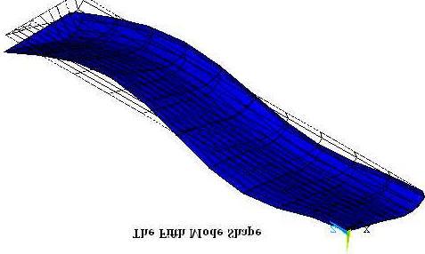
6 14. Toolbar: SAVE_DB Obtain Solution 11. Specify analysis type and options. Specify a modal analysis type. 1. Main Menu: Solution -Analysis Type-New Analysis 2. Choose Modal -» 3. OK -» 4. Main Menu: Solution -Analysis Type-Analysis Options 5. Choose Block Lanczos -» 6. Enter 5 for the No. of modes to extract -» 7. Enter 5 for the No. of modes to expand -» 8. OK -» 9. OK (All default values are acceptable for this analysis.) -» 10. Toolbar: SAVE_DB 12. Solve. 1. Main Menu: Solution -Solve-Current LS 2. Review the information in the status window, then choose File Close (Windows NT / Windows 95) 3. OK to initiate the solution -» 4. Yes -» 5. Yes -» Based on previous discussions, the warnings are accepted. The messages presented in the verification window are due to the face that PLANE42 elements have been defined but not used in the analysis. They were used to mesh a 2-D cross-sectional area. 6. Close to acknowledge that the solution is done -» Review Results 13. List the natural frequencies. 1. Main Menu: General Postproc Results Summary 2. File Close (Windows NT / Windows 95)-» 14. Animate the five mode shapes. Set the results for the first mode to be animated. 1. Main Menu: General Postproc -Read Results-First Set 2. Utility Menu: PlotCtrls Animate Mode Shape 3. OK -» For Windows NT systems only: the Media Player appears. Make sure the Auto Repeat option is selected before

7 viewing the animation. Animate the next mode shape. 4. Main Menu: General Postproc -Read Results-Next Set 5. Utility Menu: PlotCtrls Animate Mode Shape 6. OK -» Observe the second mode shape: Observe the third mode shape: Observe the fifth mode shape:
8
Chapter 2. Structural Tutorial
 Chapter 2. Structural Tutorial Tutorials> Chapter 2. Structural Tutorial Static Analysis of a Corner Bracket Problem Specification Problem Description Build Geometry Define Materials Generate Mesh Apply
file://c:\documents and Settings\sala\Configuración local\temp\~hha54f.htm
 Página 1 de 26 Tutorials Chapter 2. Structural Tutorial 2.1. Static Analysis of a Corner Bracket 2.1.1. Problem Specification Applicable ANSYS Products: Level of Difficulty: Interactive Time Required:
Bell Crank. Problem: Joseph Shigley and Charles Mischke. Mechanical Engineering Design 5th ed (New York: McGraw Hill, May 2002) page 87.
 page 87.") Problem: A cast-iron bell-crank lever, depicted in the figure below is acted upon by forces F 1 of 250 lb and F 2 of 333 lb. The section A-A at the central pivot has a curved inner surface with a radius
Problem: A cast-iron bell-crank lever, depicted in the figure below is acted upon by forces F 1 of 250 lb and F 2 of 333 lb. The section A-A at the central pivot has a curved inner surface with a radius
ANSYS. Geometry. Material Properties. E=2.8E7 psi v=0.3. ansys.fem.ir Written By:Mehdi Heydarzadeh Page 1
 Attention: This tutorial is outdated, you will be redirected automatically to the new site. If you are not redirected, click this link to the confluence site. Problem Specification Geometry Material Properties
Structural static analysis - Analyzing 2D frame
 Structural static analysis - Analyzing 2D frame In this tutorial we will analyze 2D frame (see Fig.1) consisting of 2D beams with respect to resistance to two different kinds of loads: (a) the downward
Exercise 1. 3-Point Bending Using the GUI and the Bottom-up-Method
 Exercise 1 3-Point Bending Using the GUI and the Bottom-up-Method Contents Learn how to... 1 Given... 2 Questions... 2 Taking advantage of symmetries... 2 A. Preprocessor (Setting up the Model)... 3 A.1
Structural static analysis - Analyzing 2D frame
 Structural static analysis - Analyzing 2D frame In this tutorial we will analyze 2D frame (see Fig.1) consisting of 2D beams with respect to resistance to two different kinds of loads: (a) the downward
Latch Spring. Problem:
 Problem: Shown in the figure is a 12-gauge (0.1094 in) by 3/4 in latching spring which supports a load of F = 3 lb. The inside radius of the bend is 1/8 in. Estimate the stresses at the inner and outer
Example Cantilever beam
 Course in ANSYS Example0300 Example Cantilever beam Objective: Compute the maximum deflection and locate point of maximum deflection Tasks: How should this be modelled? Compare results with results obtained
Two Dimensional Truss
 Two Dimensional Truss Introduction This tutorial was created using ANSYS 7.0 to solve a simple 2D Truss problem. This is the first of four introductory ANSYS tutorials. Problem Description Determine the
Course in ANSYS. Example0410. ANSYS Computational Mechanics, AAU, Esbjerg
 Course in Example0410 Example Frame 2D Objective: Compute the harmonic response Tasks: Perform a modal analysis Display the mode shapes Perform a harmonic analysis Topics: Topics: Start of analysis, Element
Statically Indeterminate Beam
 Problem: Using Castigliano's Theorem, determine the deflection at point A. Neglect the weight of the beam. W 1 N/m B 5 cm H 1 cm 1.35 m Overview Anticipated time to complete this tutorial: 45 minutes Tutorial
Module 1.5: Moment Loading of a 2D Cantilever Beam
 Module 1.5: Moment Loading of a D Cantilever Beam Table of Contents Page Number Problem Description Theory Geometry 4 Preprocessor 7 Element Type 7 Real Constants and Material Properties 8 Meshing 9 Loads
Module 1.6: Distributed Loading of a 2D Cantilever Beam
 Module 1.6: Distributed Loading of a 2D Cantilever Beam Table of Contents Page Number Problem Description 2 Theory 2 Geometry 4 Preprocessor 7 Element Type 7 Real Constants and Material Properties 8 Meshing
Chapter 3. Thermal Tutorial
 Chapter 3. Thermal Tutorial Tutorials> Chapter 3. Thermal Tutorial Solidification of a Casting Problem Specification Problem Description Prepare for a Thermal Analysis Input Geometry Define Materials Generate
Ansys Lab Frame Analysis
 Ansys Lab Frame Analysis Analyze the highway overpass frame shown in Figure. The main horizontal beam is W24x162 (area = 47.7 in 2, moment of inertia = 5170 in 4, height = 25 in). The inclined members
Structural modal analysis - 2D frame
 Structural modal analysis - 2D frame Determine the first six vibration characteristics, namely natural frequencies and mode shapes, of a structure depicted in Fig. 1, when Young s modulus= 27e9Pa, Poisson
ANSYS EXERCISE ANSYS 5.6 Temperature Distribution in a Turbine Blade with Cooling Channels
 I. ANSYS EXERCISE ANSYS 5.6 Temperature Distribution in a Turbine Blade with Cooling Channels Copyright 2001-2005, John R. Baker John R. Baker; phone: 270-534-3114; email: jbaker@engr.uky.edu This exercise
Course in ANSYS. Example0505. ANSYS Computational Mechanics, AAU, Esbjerg
 Course in Example0505 Example Plate Objective: Compute the buckling load Tasks: How should this be modelled? Compare results with results obtained from norm calculations? Topics: Element type, Real constants,
Structural modal analysis - 2D frame
 Structural modal analysis - 2D frame Determine the first six vibration characteristics, namely natural frequencies and mode shapes, of a structure depicted in Fig. 1, when Young s modulus= 27e9Pa, Poisson
Module 3: Buckling of 1D Simply Supported Beam
 Module : Buckling of 1D Simply Supported Beam Table of Contents Page Number Problem Description Theory Geometry 4 Preprocessor 7 Element Type 7 Real Constants and Material Properties 8 Meshing 9 Solution
NonLinear Analysis of a Cantilever Beam
 NonLinear Analysis of a Cantilever Beam Introduction This tutorial was created using ANSYS 7.0 The purpose of this tutorial is to outline the steps required to do a simple nonlinear analysis of the beam
Course in ANSYS. Example0303. ANSYS Computational Mechanics, AAU, Esbjerg
 Course in Example0303 Example Gear axle 3D Objective: Compute the maximum stress von Mise Tasks: How should this be modeled? Topics: Element type, Real constants, modeling, Plot results, output graphics,
Melting Using Element Death
 Melting Using Element Death Introduction This tutorial was completed using ANSYS 7.0 The purpose of the tutorial is to outline the steps required to use element death to model melting of a material. Element
ANSYS 5.6 Tutorials Lecture # 2 - Static Structural Analysis
 R50 ANSYS 5.6 Tutorials Lecture # 2 - Static Structural Analysis Example 1 Static Analysis of a Bracket 1. Problem Description: The objective of the problem is to demonstrate the basic ANSYS procedures
Essay 5 Tutorial for a Three-Dimensional Heat Conduction Problem Using ANSYS
 Essay 5 Tutorial for a Three-Dimensional Heat Conduction Problem Using ANSYS 5.1 Introduction The problem selected to illustrate the use of ANSYS software for a three-dimensional steadystate heat conduction
Coupled Structural/Thermal Analysis
 Coupled Structural/Thermal Analysis Introduction This tutorial was completed using ANSYS 7.0 The purpose of this tutorial is to outline a simple coupled thermal/structural analysis. A steel link, with
Course in ANSYS. Example0154. ANSYS Computational Mechanics, AAU, Esbjerg
 Course in Example0154 Example Frame 2D E = 210000N/mm 2 n = 0.3 L= 1000mm H = 1000mm a = 20mm b = 50mm c = 400mm F = 10000N I = 208333N/mm 4 Example0154 2 Example Frame 2D Objective: Compute the maximum
Transient Thermal Conduction Example
 Transient Thermal Conduction Example Introduction This tutorial was created using ANSYS 7.0 to solve a simple transient conduction problem. Special thanks to Jesse Arnold for the analytical solution shown
Institute of Mechatronics and Information Systems
 EXERCISE 4 Free vibrations of an electrical machine model Target Getting familiar with the fundamental issues of free vibrations analysis of a simplified model of an electrical machine, with the use of
Buckling of Euler Column
 Problem: An Euler column with one end fixed and one end free is to be made of an aluminum alloy (E = 71 GPa). The cross sectional area of the column is 600 mm and the column is.5 m long. Determine the
6. Results Combination in Hexagonal Shell
 6. Results Combination in Hexagonal Shell Applicable CivilFEM Product: All CivilFEM Products Level of Difficulty: Moderate Interactive Time Required: 0 minutes Discipline: Load combinations results Analysis
Module 1.7: Point Loading of a 3D Cantilever Beam
 Module 1.7: Point Loading of a D Cantilever Beam Table of Contents Page Number Problem Description Theory Geometry 4 Preprocessor 6 Element Type 6 Material Properties 7 Meshing 8 Loads 9 Solution 15 General
Course in ANSYS. Example Truss 2D. Example0150
 Course in ANSYS Example0150 Example Truss 2D Objective: Compute the maximum deflection Tasks: Display the deflection figure? Topics: Topics: Start of analysis, Element type, Real constants, Material, modeling,
NonLinear Materials AH-ALBERTA Web:
 NonLinear Materials Introduction This tutorial was completed using ANSYS 7.0 The purpose of the tutorial is to describe how to include material nonlinearities in an ANSYS model. For instance, the case
Course in ANSYS. Example0504. ANSYS Computational Mechanics, AAU, Esbjerg
 Course in Example0504 Example Cantilever beam Objective: Compute the buckling load Tasks: Display the deflection figure? Topics: Topics: Start of analysis, Element type, Real constants, Material, modeling,
Course in ANSYS. Example0601. ANSYS Computational Mechanics, AAU, Esbjerg
 Course in Example0601 Example Turbine Blade Example0601 2 Example Turbine Blade Objective: Solve for the temperature distribution within the 6mm thick turbine blade, with 2mm x 6mm rectangular cooling
Module 1.2: Moment of a 1D Cantilever Beam
 Module 1.: Moment of a 1D Cantilever Beam Table of Contents Page Number Problem Description Theory Geometry Preprocessor 6 Element Type 6 Real Constants and Material Properties 7 Meshing 9 Loads 10 Solution
Course in ANSYS. Example0153. ANSYS Computational Mechanics, AAU, Esbjerg
 Course in Example0153 Example Offshore structure F Objective: Display the deflection figure and von Mises stress distribution Tasks: Import geometry from IGES. Display the deflection figure? Display the
3. Check by Eurocode 3 a Steel Truss
 TF 3. Check by Eurocode 3 a Steel Truss Applicable CivilFEM Product: All CivilFEM Products Level of Difficulty: Moderate Interactive Time Required: 40 minutes Discipline: Structural Steel Analysis Type:
Example Plate with a hole
 Course in ANSYS Example Plate with a hole A Objective: Determine the maximum stress in the x-direction for point A and display the deformation figure Tasks: Create a submodel to increase the accuracy of
Institute of Mechatronics and Information Systems
 EXERCISE 2 Free vibrations of a beam arget Getting familiar with the fundamental issues of free vibrations analysis of elastic medium, with the use of a finite element computation system ANSYS. Program
Stresses in an Elliptical Beam
 Problem: An offset tensile link is shaped to clear an obstruction with a geometry as shown in the figure. The cross section at the critical location is elliptical, with a major axis of 4 in and a minor
Course in ANSYS. Example0152. ANSYS Computational Mechanics, AAU, Esbjerg
 Course in Example0152 Example Truss 2D E = 210e09N/m 2 n = 0.3 L1 = L2 = L3 = 3.6m H = 3.118m a = b = 0.050mm F1 = 280kN F2 = 210kN F3 = 280kN F4 = 360kN Example0152 2 Example Truss 2D Objective: Compute
ECE421: Electronics for Instrumentation
 ECE421: Electronics for Instrumentation Lecture #8: Introduction to FEA & ANSYS Mostafa Soliman, Ph.D. March 23 rd 2015 Mostafa Soliman, Ph.D. 1 Outline Introduction to Finite Element Analysis Introduction
Torsional-lateral buckling large displacement analysis with a simple beam using Abaqus 6.10
 Torsional-lateral buckling large displacement analysis with a simple beam using Abaqus 6.10 This document contains an Abaqus tutorial for performing a buckling analysis using the finite element program
Course in ANSYS. Example0500. ANSYS Computational Mechanics, AAU, Esbjerg
 Course in Example0500 Example Column beam Objective: Compute the critical buckling load and display the mode shape Tasks: Create a table and compare results with results obtained from buckling theory?
ANSYS Tutorials. Table of Contents. Grady Lemoine
 ANSYS Tutorials Grady Lemoine Table of Contents Example 1: 2-D Static Stress Analysis in ANSYS...2 Example 2: 3-D Static Stress Analysis...5 Example 3: 2-D Frame With Multiple Materials and Element Types...10
ANSYS Mechanical APDL Tutorials
 ANSYS Mechanical APDL Tutorials ANSYS, Inc. Southpointe 275 Technology Drive Canonsburg, PA 15317 ansysinfo@ansys.com http://www.ansys.com (T) 724-746-3304 (F) 724-514-9494 Release 13.0 November 2010 ANSYS,
Interface with FE programs
 Page 1 of 47 Interdisciplinary > RFlex > Flexible body Interface Interface with FE programs RecurDyn/RFlex can import FE model from ANSYS, NX/NASTRAN, MSC/NASTRAN and I-DEAS. Figure 1 RecurDyn/RFlex Interface
MECH 3130: Mechanics of Materials. Fall Laboratory Manual. Volume II
 MECH 3130: Mechanics of Materials Fall 2015 Laboratory Manual Volume II Instructor Dr. Peter Schwartz Dr. Nels Madsen Lab Teaching Assistants Quang Nguyen: qzn0003@auburn.edu Abhiram Pasumarthy rzp0025@auburn.edu
FINITE ELEMENT ANALYSIS OF A PROPPED CANTILEVER BEAM
 FINITE ELEMENT ANALYSIS OF A PROPPED CANTILEVER BEAM Problem Description: Instructor: Professor James Sherwood Revised: Venkat Putcha, Dimitri Soteropoulos Programs Utilized: HyperMesh Desktop 12.0, OptiStruct,
ANSYS Tutorial Version 6
 ANSYS Tutorial Version 6 Fracture Analysis Consultants, Inc www.fracanalysis.com Revised: November 2011 Table of Contents: 1.0 Introduction... 4 2.0 Tutorial 1: Crack Insertion and Growth in a Cube...
Installation Guide. Beginners guide to structural analysis
 Installation Guide To install Abaqus, students at the School of Civil Engineering, Sohngaardsholmsvej 57, should log on to \\studserver, whereas the staff at the Department of Civil Engineering should
11. Push-over analysis
 . Push-over analysis Applicable CivilFEM Product: All CivilFEM Products Level of Difficulty: Moderate Interactive Time Required: 90 minutes Discipline: Structural Steel Analysis Type: Push Over Element
Appendix B: Creating and Analyzing a Simple Model in Abaqus/CAE
 Getting Started with Abaqus: Interactive Edition Appendix B: Creating and Analyzing a Simple Model in Abaqus/CAE The following section is a basic tutorial for the experienced Abaqus user. It leads you
Linear Bifurcation Buckling Analysis of Thin Plate
 LESSON 13a Linear Bifurcation Buckling Analysis of Thin Plate Objectives: Construct a quarter model of a simply supported plate. Place an edge load on the plate. Run an Advanced FEA bifurcation buckling
SolidWorks. An Overview of SolidWorks and Its Associated Analysis Programs
 An Overview of SolidWorks and Its Associated Analysis Programs prepared by Prof. D. Xue University of Calgary SolidWorks - a solid modeling CAD tool. COSMOSWorks - a design analysis system fully integrated
ME 442. Marc/Mentat-2011 Tutorial-1
 ME 442 Overview Marc/Mentat-2011 Tutorial-1 The purpose of this tutorial is to introduce the new user to the MSC/MARC/MENTAT finite element program. It should take about one hour to complete. The MARC/MENTAT
CHAPTER 8 FINITE ELEMENT ANALYSIS
 If you have any questions about this tutorial, feel free to contact Wenjin Tao (w.tao@mst.edu). CHAPTER 8 FINITE ELEMENT ANALYSIS Finite Element Analysis (FEA) is a practical application of the Finite
Modal Analysis of a Steel Frame
 Modal Analysis of a Steel Frame Name: Sushanth Kumareshwar Panchaxrimath Department: Mechanical Engineering Course: Powertrain NVH of Electrified Vehicles Date: 11/26/2016 SUMMARY A dynamic modal analysis
3 AXIS STANDARD CAD. BobCAD-CAM Version 28 Training Workbook 3 Axis Standard CAD
 3 AXIS STANDARD CAD This tutorial explains how to create the CAD model for the Mill 3 Axis Standard demonstration file. The design process includes using the Shape Library and other wireframe functions
Modelling and Analysis Lab (FEA)
") Channabasaveshwara Institute of Technology (Affiliated to VTU, Belagavi & Approved by AICTE, New Delhi) (NAAC Accredited & ISO 9001:2015 Certified Institution) NH 206 (B.H. Road), Gubbi, Tumakuru 572 216.
Channabasaveshwara Institute of Technology (Affiliated to VTU, Belagavi & Approved by AICTE, New Delhi) (NAAC Accredited & ISO 9001:2015 Certified Institution) NH 206 (B.H. Road), Gubbi, Tumakuru 572 216.
Figure Random vibration analysis of a simply supported beam
 Example 6.5.8-1 [Spectrum Analysis] Determine the first two natural frequencies and the response of a damped two degree of freedom system subject to a random acceleration with a spectral density function
FINITE ELEMENT ANALYSIS OF A PLANAR TRUSS
 Problem Description: FINITE ELEMENT ANALYSIS OF A PLANAR TRUSS Instructor: Professor James Sherwood Revised: Dimitri Soteropoulos Programs Utilized: Abaqus/CAE 6.11-2 This tutorial explains how to build
Practical modeling of diaphragm walls and foundation rafts with piles part I
 Practical modeling of diaphragm walls and foundation rafts with piles part I FE mesh This example concerns modeling of a deep excavation protected by concrete wall an then by a construction of foundation
300 N All lengths in meters. Step load applied at time 0.0.
 Problem description In this problem, we subject the beam structure of problem 1 to an impact load as shown. 300 N 0.02 0.02 1 All lengths in meters. Step load applied at time 0.0. E = 2.07 10 11 N/m 2
H Stab and V Stab. Chapter 6. Glider. A. Open and Save as "H STAB". Step 1. Open your STABILIZER BLANK file.
 Chapter 6 Glider H Stab and V Stab A. Open and Save as "H STAB". Step 1. Open your STABILIZER BLANK file. Step 2. Click File Menu > Save As. Step 3. Key-in H STAB for the filename and press ENTER. B. Sketch
FINITE ELEMENT ANALYSIS OF A PROPPED CANTILEVER BEAM
 FINITE ELEMENT ANALYSIS OF A PROPPED CANTILEVER BEAM Problem Description: Instructor: Professor James Sherwood Revised: Venkat Putcha, Dimitri Soteropoulos, Sanjay Nainani Programs Utilized: HyperMesh
Glider. Wing. Top face click Sketch. on the Standard Views. (S) on the Sketch toolbar.
 on the Sketch toolbar.") Chapter 5 Glider Wing 4 Panel Tip A. Open and Save As "WING 4 PANEL". Step 1. Open your WING BLANK file. Step 2. Click File Menu > Save As. Step 3. Key-in WING 4 PANEL for the filename and press ENTER.
Chapter 5 Glider Wing 4 Panel Tip A. Open and Save As "WING 4 PANEL". Step 1. Open your WING BLANK file. Step 2. Click File Menu > Save As. Step 3. Key-in WING 4 PANEL for the filename and press ENTER.
Module 1: Basics of Solids Modeling with SolidWorks
 Module 1: Basics of Solids Modeling with SolidWorks Introduction SolidWorks is the state of the art in computer-aided design (CAD). SolidWorks represents an object in a virtual environment just as it exists
Modeling a Shell to a Solid Element Transition
 LESSON 9 Modeling a Shell to a Solid Element Transition Objectives: Use MPCs to replicate a Solid with a Surface. Compare stress results of the Solid and Surface 9-1 9-2 LESSON 9 Modeling a Shell to a
Exercise 9a - Analysis Setup and Loading
 Exercise 9a - Analysis Setup and Loading This exercise will focus on setting up a model for analysis. At the end of this exercise, you will run an analysis in OptiStruct. While this exercise is focused
Quarter Symmetry Tank Stress (Draft 4 Oct 24 06)
") Quarter Symmetry Tank Stress (Draft 4 Oct 24 06) Introduction You need to carry out the stress analysis of an outdoor water tank. Since it has quarter symmetry you start by building only one-fourth of
Quarter Symmetry Tank Stress (Draft 4 Oct 24 06) Introduction You need to carry out the stress analysis of an outdoor water tank. Since it has quarter symmetry you start by building only one-fourth of
Release 10. Kent L. Lawrence. Mechanical and Aerospace Engineering University of Texas at Arlington SDC PUBLICATIONS
 ANSYS Release 10 Tutorial Kent L. Lawrence Mechanical and Aerospace Engineering University of Texas at Arlington SDC PUBLICATIONS Schroff Development Corporation www.schroff.com www.schroff-europe.com
Finite Element Analysis using ANSYS Mechanical APDL & ANSYS Workbench
 Finite Element Analysis using ANSYS Mechanical APDL & ANSYS Workbench Course Curriculum (Duration: 120 Hrs.) Section I: ANSYS Mechanical APDL Chapter 1: Before you start using ANSYS a. Introduction to
ANSYS Tutorial Release 11.0
 ANSYS Tutorial Release 11.0 Structural & Thermal Analysis Using the ANSYS Release 11.0 Environment Kent L. Lawrence Mechanical and Aerospace Engineering University of Texas at Arlington SDC PUBLICATIONS
Abaqus/CAE (ver. 6.10) Stringer Tutorial
 Stringer Tutorial") Abaqus/CAE (ver. 6.10) Stringer Tutorial Problem Description A table made of steel tubing with a solid steel top and shelf is loaded with an oblique impulse load. Determine the transient response of the
Abaqus/CAE (ver. 6.10) Stringer Tutorial Problem Description A table made of steel tubing with a solid steel top and shelf is loaded with an oblique impulse load. Determine the transient response of the
5. Shell Reinforcement According To Eurocode 2
 5. Shell Reinforcement According To Eurocode Applicable CivilFEM Product: All CivilFEM Products Level of Difficulty: Moderate Interactive Time Required: 5 minutes Discipline: Concrete Shell Reinforcement
Introduction to MSC.Patran
 Exercise 1 Introduction to MSC.Patran Objectives: Create geometry for a Beam. Add Loads and Boundary Conditions. Review analysis results. MSC.Patran 301 Exercise Workbook - Release 9.0 1-1 1-2 MSC.Patran
Case Study 1: Piezoelectric Rectangular Plate
 Case Study 1: Piezoelectric Rectangular Plate PROBLEM - 3D Rectangular Plate, k31 Mode, PZT4, 40mm x 6mm x 1mm GOAL Evaluate the operation of a piezoelectric rectangular plate having electrodes in the
FEA of Composites Classical Lamination Theory Example 1
 FEA of Composites Classical Lamination Theory Example 1 22.514 Instructor: Professor James Sherwood Author: Dimitri Soteropoulos Revised by Jacob Wardell Problem Description: A four layer [0/90] s graphite-epoxy
FINITE ELEMENT ANALYSIS OF A PLANAR TRUSS
 FINITE ELEMENT ANALYSIS OF A PLANAR TRUSS Instructor: Professor James Sherwood Revised: Michael Schraiber, Dimitri Soteropoulos, Sanjay Nainani Programs Utilized: HyperMesh Desktop v2017.2, OptiStruct,
Sliding Split Tube Telescope
 LESSON 15 Sliding Split Tube Telescope Objectives: Shell-to-shell contact -accounting for shell thickness. Creating boundary conditions and loads by way of rigid surfaces. Simulate large displacements,
Truss Optimization. Problem:
 Problem: Assuming that the compression members of the truss showing in the figure will not buckle, find the minimum cross sectional area of each member using an allowable stress of 50 MPa. The dimensions
Creating and Analyzing a Simple Model in Abaqus/CAE
 Appendix B: Creating and Analyzing a Simple Model in Abaqus/CAE The following section is a basic tutorial for the experienced Abaqus user. It leads you through the Abaqus/CAE modeling process by visiting
Kratos Multi-Physics 3D Fluid Analysis Tutorial. Pooyan Dadvand Jordi Cotela Kratos Team
 Kratos Multi-Physics 3D Fluid Analysis Tutorial Pooyan Dadvand Jordi Cotela Kratos Team Kratos 3D Fluid Tutorial In this tutorial we will solve a simple example using GiD and Kratos Geometry Input data
Abaqus CAE Tutorial 6: Contact Problem
 ENGI 7706/7934: Finite Element Analysis Abaqus CAE Tutorial 6: Contact Problem Problem Description In this problem, a segment of an electrical contact switch (steel) is modeled by displacing the upper
Normal Modes - Rigid Element Analysis with RBE2 and CONM2
 APPENDIX A Normal Modes - Rigid Element Analysis with RBE2 and CONM2 T 1 Z R Y Z X Objectives: Create a geometric representation of a tube. Use the geometry model to define an analysis model comprised
Sliding Block LESSON 26. Objectives: Demonstrate the use of Contact LBCs in a simple exercise.
 LESSON 26 Sliding Block 5 Objectives: Demonstrate the use of Contact LBCs in a simple exercise. Present method for monitoring a non-linear analysis progress. 26-1 26-2 LESSON 26 Sliding Block Model Description:
Structural & Thermal Analysis Using the ANSYS Workbench Release 12.1 Environment
 ANSYS Workbench Tutorial Structural & Thermal Analysis Using the ANSYS Workbench Release 12.1 Environment Kent L. Lawrence Mechanical and Aerospace Engineering University of Texas at Arlington SDC PUBLICATIONS
Linear and Nonlinear Analysis of a Cantilever Beam
 LESSON 1 Linear and Nonlinear Analysis of a Cantilever Beam P L Objectives: Create a beam database to be used for the specified subsequent exercises. Compare small vs. large displacement analysis. Linear
Module 1.7W: Point Loading of a 3D Cantilever Beam
 Module 1.7W: Point Loading of a 3D Cantilever Beam Table of Contents Page Number Problem Description 2 Theory 2 Workbench Analysis System 4 Engineering Data 5 Geometry 6 Model 11 Setup 13 Solution 14 Results
TUTORIAL 7: Stress Concentrations and Elastic-Plastic (Yielding) Material Behavior Initial Project Space Setup Static Structural ANSYS ZX Plane
 Material Behavior Initial Project Space Setup Static Structural ANSYS ZX Plane") TUTORIAL 7: Stress Concentrations and Elastic-Plastic (Yielding) Material Behavior In this tutorial you will learn how to recognize and deal with a common modeling issues involving stress concentrations
TUTORIAL 7: Stress Concentrations and Elastic-Plastic (Yielding) Material Behavior In this tutorial you will learn how to recognize and deal with a common modeling issues involving stress concentrations
Adjust model for 3D Printing. Direct modeling tools 13,0600,1489,1616(SP6)
") Adjust model for 3D Printing Direct modeling tools 13,0600,1489,1616(SP6) Sometimes, the model needs to be prepared or adapted for printing. Adding material, change of a draft angles are an example. In
Adjust model for 3D Printing Direct modeling tools 13,0600,1489,1616(SP6) Sometimes, the model needs to be prepared or adapted for printing. Adding material, change of a draft angles are an example. In
University of Utah ME EN 6510/5510 Introduction to Finite Elements Fall 2005
 University of Utah ME EN 6510/5510 Introduction to Finite Elements Fall 2005 Running ANSYS on the CADE lab workstations CADE Lab Accounts You need to get account information in EMCB 224 from the operators
Command. Command BOUNDARY CONDITIONS. 4.4 Mode analysis of a one-axis precision moving table using elastic hinges 201
 4.4 Mode analysis of a one-axis precision moving table using elastic hinges 201 C D Figure 4.96 Window of Element Sizes on Picked Lines. (5) Pick the area of the table on NSYS Graphics window and click
Tutorial 2: Rock Cutting Disc 3D. Rock Cutting Disc
 Rock Cutting Disc This tutorial details the simulation of a process with granular non-cohesive material, concretely a Mill. Advanced and specific aspects should be clarified during training seminars using
FINITE ELEMENT ANALYSIS OF A PLANAR TRUSS
 FINITE ELEMENT ANALYSIS OF A PLANAR TRUSS Instructor: Professor James Sherwood Revised: Michael Schraiber, Dimitri Soteropoulos Programs Utilized: HyperMesh Desktop v12.0, OptiStruct, HyperView This tutorial
Stiffness of Tapered Beam
 Problem: A bar in tension has a conical shape of length L. The task is to find the stiffness of the tapered section. Compare the stiffness given by ANSYS to the theoretical stiffness given by: EA1 ( r2