CVGIP: Graphical Models and Image Processing, Academic Press, 60(5),pp , September 1998.
|
|
|
- Jeffrey Harrison
- 5 years ago
- Views:
Transcription
1 CVGIP: Graphical Models and Image Processing, Academic Press, 60(5),pp , September Contour-Based Warping Kwai Hung Chan Rynson W.H. Lau Computer Graphics and Media Laboratory Department of Computing The Hong Kong Polytechnic University, Hong Kong Paper Title Contact Author Address : Contour-Based Warping : Dr. Rynson W.H. Lau : Department of Computer Science City University of Hong Kong Tat Chee Avenue, Kowloon, Hong Kong Telephone No. : (852) Fax No. : (852) rynson@cs.cityu.edu.hk 1
2 Contour-Based Warping Abstract In this paper, a new warping technique called contour-based warping is presented. Feature contours of objects are dened and mapped to their target shapes. This allows the user greater exibility in dening the warping with minimal eort. Two image warping methods are introduced in this paper and both are based on the concept of mapping contours. The peel-and-resample method can warp simple image objects with a single inner-feature in a short time, but suers from the problems of misalignment and inability of handling multiple features. The wave propagation method solves these two problems. Unlike most existing methods, this method warps image objects based on specied feature contours instead of points or vectors. Results of this method demonstrate that increasing the number of contour features distributed on the warping image reduces the computational time. However, it is slower compared with the peel-and-resample method when warping simple image objects with a single inner-feature. 2
3 1 Introduction Image warping is the geometrical mapping of an image from one spatial domain (the source shape) onto another (the target shape). Digital image warping involves issues such as spatial transformation, resampling and antialiasing. This has been extensively discussed in [10][19]. Various image warping techniques were proposed and dierent results were obtained. They can be categorized into three main types of methods - patch-based, point-based and vector-based warping methods. In patch-based warping, the spatial domain of the source image is rstly subdivided into a set of small patches. Then another set of patches is obtained by similar subdivision of the target image. The image is warped by transforming each patch of the source to its corresponding patch of the target. The pioneer of this type of method is the 2-pass mesh warping algorithm [17]. With this technique, a 2-pass transformation replaces a 2-D transformation with a sequence of orthogonal 1-D transformations. There are also investigations of other patch-based warping methods such as [8][11] which map triangular patch-pairs. In point-based warping, important points are used as the basic corresponding mapping feature pairs. Many point-based methods treat warping as a scattered-data interpolation function. Specic interpolation functions which can interpolate through all feature points are used. A warping technique based on radial basis function was introduced in [1] and was applied in synthesizing simple facial expression. Radial basis function is an eective function in multivariate interpolation of scattered data without preferred orientation. A similar approach was presented in [2][4]. Instead of radial basis function, they use thin plate splines as the basis of the interpolation function. Another point-based method [12][13] handles the warping as a free-form deformation problem depending on 2D feature points. A more complete discussion of point-based warping is given in [14]. Vector-based warping techniques use vector pairs as the basis of the warping transformation. Vector-based image warping was rstly proposed by Beier and Neely [3]. A vector pair denes a coordinate mapping between them. The displacement of any point in the image is then a weighted sum of the mappings due to all specied vector feature pairs. 3
4 In practical situations, very often we need to warp image objects of arbitrary shapes. One of the main concerns is the warping of the boundary contours of the objects in a controllable way, such as the example shown in gure 1. The matching of corresponding pairs in existing methods may be very time consuming if a ne approximation is required. It is because they are not based on mapping contours and the computational cost is proportional to the number of feature pairs specied. In this paper, we introduce a new warping technique called contour-based warping that warps objects with arbitrary contours in a controllable way, and two warping methods that are based on this new warping technique. Object Boundary Mapping Important Inner Feature Mapping Source Image Target Image Figure 1: Warping of image objects with arbitrary contours. The two warping methods introduced are the peel-and-resample method and the wave propagation method. The peel-and-resample method is fast and simple. It can warp an object with a single feature inside. However, it suers from the problems of misalignment and inability of handling multiple inner-features, as will be discussed in section 3.4. The wave propagation method solves these two problems. It warps an image in a manner similar to wave propagated from the dened feature contours. Results show that the increase in the number of specied contour features distributed on the warping image can reduce the computational time. This indicates that, unlike other existing methods, the computational time of this method is not proportional to the number of features used. However, compared with the peel-and-resample method, a longer computational time is required when warping simple objects with a single inner-feature. The rest of the paper is organized as follows. Section 2 describes the basic concept of contour- 4
5 based warping. Section 3 presents the peel-and-resample method while section 4 presents the wave propagation method. Finally, section 5 draws a conclusion of this paper and discusses possible future directions. 2 Principle Concept of Contour-Based Warping To develop a warping technique which warps image objects with arbitrary shapes, we have proposed the idea of seeking the contour correspondence of the source and target images in our earlier paper [5]. Contour pairs are determined and those in the source are mapped onto those in the target, as shown in gure 2. Contour Mapping of a unique point C(u, v) -> (u, v ) (u, v) (u, v ) Corresponding Contour Mapping Source Image Target Image Figure 2: Idea of contour mapping for image warping. Ideally, a mathematical model should be used to map each point from the source to the target. In continuous domain, given a set of contour pairs f(c 1 ; C 0 1 ); (C 2; C 0 2 ); ::::; (C n; C 0 n )g where contour C i can be considered as a continuous parametric function that maps [0; 1] to < 2. We dene a continuous mapping function, C W arp, which maps each point (u; v) in source domain to point (u 0 ; v 0 ) in target domain : (u 0 ; v 0 ) = C W arp(u; v) such that (u 0 ; v 0 ) 2 C 0 i ) (u; v) 2 C i; i 2 [1; n] 5
6 However, there is no easy way to mathematically dene the correct contour correspondence of arbitrary planar objects as in gure 2. Here, we apply mathematical morphology in nding the contour correspondence. Mathematical morphology is a special branch of nonlinear image processing. One of its main applications is simplifying images and preserving the main shape of objects. It has been used in image preprocessing, such as shape simplication and noise ltering, and enhancing structures of image objects such as thinning and thickening. A morphological operation is given by the relation of the image object, I, with another structuring element set, S. The structuring element set is applied to each spatial point of the image object with the specied relation. Two basic morphological operators are used in this paper : erosion and dilation. Mathematically, erosion is a vector subtraction operation of the structuring element set to the image object while dilation is a vector addition. erosion(i; S) = fxj(x + s) 2 I; 8s 2 Sg (1) dilation(i; S) = fxjx = i + s; 8i 2 I; 8s 2 Sg (2) Theoretically, mathematical morphology can be applied to continuous domain. However, digital version is mostly handled in practical situation. A detailed introduction of mathematical morphology can be obtained from related materials [7][9][16]. Our contour-based warping is initially based on a peel-and-resample method. It is ecient but it suers from the misalignment problem and the inability of handling multiple inner-features. A second method, called the wave propagation method, was then developed. This method overcomes the two limitations of the peel-and-resample method. However, it is slower than the peel-andresample method when warping objects with a single inner-feature. 6
7 3 Peel-and-Resample method The very rst inspiration of this method was drawn from a skeleton-based warping method introduced by [18]. A planar image object with arbitrary shape is warped to another based on a skeletal thinning technique. The image is partitioned into layers, similar to peeling an object. A three pass resampling process is then performed to transform the layers rstly to a rectangular form in the original space, then to the rectangular form in the output space and nally to the output image. However, no consideration has been made on the warping eect inside the object and no control has been given on how to change the features inside the image object. Our peel-and-resample method solves this problem. In this method, the contours are determined/peeled by two morphological operators : erosion and dilation. The peeled contours are then resampled to a standard rectangular shape for mapping. 3.1 Erosion-Based Contour Determination The erosion operator can be realised as a set operation which uses vector subtraction of elements, or pixels in image processing. This eect is equivalent to eroding an object layer by layer. The eroded layer can be treated as the corresponding contour away from the original boundary. To determine the corresponding contour pairs of the original and nal objects, the peeled contours or layers of the original object (obtained by eroding function E s ) is transformed onto a rectangular grid (by rectangularization function R s ) and then resampled to the contours of the nal image (by inverse of destination eroding and rectangularization functions E 01 d process of warping an object by using the erosion operator. R01 d ). Figure 3 shows the Thus, each point p in the source is mapped to p 0 in the destination : p 0 = Erode(p) = E 01 d (R01 d (R s(e s (p)))) (3) When determining the contours between the boundary of an object and its inside feature, erosion provides no control of the warping eect inside the outer boundary. Under such situation, the dilation operator can be used to extract the corresponding contours. 7
8 Source Image Target Image Es Contour Determination -1 Ed Contour Determination Contour Strips Resampling Resampling Rs Rectangular Form -1 Rd Figure 3: Principle of warping using the erosion operator. 8
9 3.2 Dilation-Based Contour Determination Let us imagine that a stone with an arbitrary shape is thrown into the water. When the stone has just made contact with the water surface, water wave starts forming and propagating outwards. This process is similar to the dilation operation in mathematical morphology, which expands an object layer by layer in all directions. Analogous to the water wave phenomenon, when an image object with an inner-feature is required to be warped in a controllable way, we treat the inside object as the stone being thrown. A dilation operator can be used to determine the \propagating water waves", and thus the contours between the main object boundary and the boundary of the inner-feature. The peeling of the object layers starts from the boundary of the inside feature and proceeds outwards as shown in gure 4. Inner Feature Boundaries Contour Mapping Object Boundaries Source Image Target Image Figure 4: Contour determination using dilation. Ideally, the contours have to be determined mathematically and correctly in order to have an accurate mapping of the corresponding contour pairs. However, erosion and dilation are pixel-based operations which process the image in pixel interval. Thus, the ideal contour which in fact may be fractional in pixel space cannot be obtained by these two primary morphological operators. In our dilation case, we connect the contour segments which have reached the boundary with the boundary contour as shown in gure 5. However, this causes the awkward warping eect where a large area of the boundary of the nal image has the same pixel values. To solve this problem, additional resampling of the rectangular grid is suggested here to get 9
10 Boundary problem occurs when pixel-based contour reaches the outer boundary Corresponding Contour Mapping Source Image Target Image Figure 5: Boundary problem of dilation in determining contours. rid of the duplicated boundary pixels so that a correct contour can be approximated as shown in gure 6. In the diagram, the black areas represent the overlapping regions of the contour strips. These areas are removed in the additional resampling operation. Similar to the Eroding function, each point p in the source is mapped to p 0 in the destination by p 0 = Dilate(p) = D 01 d (R01 d (B01 d (B s(r s (D s (p)))))) (4) 3.3 Warping Objects with a Single Inner-Feature To warp an object with a single inner-feature, we separate the problem into two parts. In the rst part, we treat the single inner-feature as a warping object without inner-feature. We use the erosion operator to determine the warped position of each point inside this inner-feature. In the second part, we handle the region between the inner-feature and the object boundary. Dilation operation is used and each point in this region is mapped according to the determined contour mapping. Thus, given a set of non-overlapping feature contour pairs with two elements only, f(c 1 ; C 0 1); (C 2 ; C 0 2)g where (C 1 ; C1 0 ) is the object boundary contour pair and (C 2; C2 0 ) is the boundary contour pair of 10
11 Source Image Target Image Contour Determination Ds -1 Dd Contour Determination Contour Strips Resampling R s -1 Rd Resampling Rectangular Form with Boundary Additional Resampling B s -1 Bd Additional Resampling Rectangular Form Figure 6: Handling the boundary problem of dilation. 11
12 the inner-feature, we solve the problem by using the Erode-Dilate E D function below : E D(u; v) = 8>< >: Erode(u; v) if (u; v) inside C 2 Dilate(u; v) otherwise (5) 3.4 Results and Discussions Figure 7 demonstrates some results of this method. Image a shows a human head of resolution Image b shows the dilated contours between the object boundary (the face silhouette) and an inner feature (the nose), while image c shows the input image overlaid with the determined contours. The contours inside the inner feature were determined by using the erosion operator and warped directly. The contours between the object boundary and the inner feature were determined by using the dilation operator. Image d shows target shapes of the face and the nose. Image e is the warped image from source b to target d. The resampled rectangular form R s (D s (p)), the boundary removed rectangular form B s (R s (D s (p))), and the mapped rectangular form B 01 (B d s(r s (D s (p)))) are shown in the top, middle and bottom diagrams of image f respectively. Note that the dened contours of the head and the nose in the destination mask are irregular, and the image is warped to a funny shape. We tested the program on a SUN SPARC 10 system and the processing time required to produce the warped image was about 2.5 seconds. The computational time is only proportional to the size of the specied region, thus the region inside the face silhouette in this example of the image, of the image to be warped. However, two basic problems were found and needed to be solved - the misalignment problem and the inability of handling multiple inner-features. The misalignment problem is that some pixels may not be able to retain the neighborhood relationship with their adjacent pixels after the warping process. Images h and i in gure 7 show an example of this case. The warped image h is generated by mapping the source contours in image b to those in image g. We can see that the eye region of the warped face is misaligned. Image i shows the magnication of the warped eye region. It clearly illustrates the misalignment problem. For a continuous and smooth mapping, the spatial adjacency of pixels must be maintained. 12
 (d)")
 (h)")


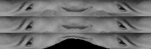
13 (a) (b) (c) (d) (e) (f) (g) (h) (i) Figure 7: Results of the peel-and-resample method. 13
14 The second problem is that the peel-and-resample method can only handle objects with a single feature inside. In the case of multiple inner features, the whole warping process needs to be solved by a weighted sum approach of partitioned sub-problems. Each sub-problem consists of the object boundary and one of the inner features only. It is simply a single inner-feature problem discussed in section 3.3. However, this cannot guarantee an appropriate warping and the desired warping eect may not be obtained. Wave propagation method is introduced to solve these problems. It warps an image in a manner similar to wave propagation. 4 Wave Propagation Method In wave propagation method, the misalignment problem of the peel-and-resample method is overcome by introducing linking force to maintain the geometrical relationship of neighboring pixels. This eectively forms a linking grid to the image. As such, image warping can be realized as deforming a linking grid by wave propagation based on specied feature contours. 4.1 Equilibrium of the Linking Grid In order to maintain the neighborhood relationship, each spatial point in the image domain is connected to adjacent neighboring points by linking forces. Here, we only consider preserving the relationship of 4-connected neighborhood. As shown in gure 8, the neighborhood relationship of the center pixel with the 4 adjacent pixels (drawn in black dot) is retained by the linking force. Other non-neighbors are kept away from the linking force region. At equilibrium state of the linking grid, any point p having the set of neighboring pixels N p : X q2np F l (p; q) + F a (p) = 0 (6) where F l (p; q) is the linking force between points p and q. F a (p) is an additional force used to characterize the warping eect. For example, we may consider F a (p) as a friction force. When it is equal to zero, the linking grid will be formed in a way that all pixel will tend to be evenly 14
15 neighboring pixels non-neighboring pixel warping linking force region Figure 8: Maintaining the neighborhood relationship by linking forces. distributed. When it is a reaction force with factor proportional to the distance of the pixel p from the dened contour, the warping will tend to be localized. Because solving the equilibrium problem mathematically is impractical, we use an iterative approach in the implementation of the method instead. 4.2 Wave Propagation Given a set of n feature contour pairs : C = ((C 1 ; C 0 1); (C 2 ; C 0 2); :::::; (C n ; C 0 n)) where C i and Ci 0, i 2 [1; n], are the source and the corresponding target contours. When warping starts from anchoring each given source contour C i to the position of its corresponding destination contour Ci 0, its neighbors start moving accordingly. The linking force will force the adjacent neighbors to shift to the new positions such that the linking force between them can be minimized to zero. Similar to the concept of wave propagation, the \moving wave" will propagate from the given source contours to their neighbors layer by layer. Thus image warping becomes a process of deforming the linking grid. As mentioned earlier, because solving the equilibrium problem mathematically is impractical, we use an iterative approach in the implementation of the technique. In each iteration cycle, each pixel which is close to the feature contours is rstly moved to a new position so that the summation of all its linking forces is close to zero. Then the process will propagate to pixels further away from 15


 In addition to solving the misalignment problem, this method also solves the problem of handling multiple inner-features in the peel-and-resample method naturally.")

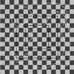
16 the feature contours. The iteration cycle continues until an equilibrium state is reached. The process of deforming a checkerboard image through wave propagation is illustrated in gure 9. The original rectangular feature contours in black color are mapped to the destination feature contours having arbitrary shape in white color as shown in the original checkerboard image a. The waves start propagating from the \anchored" feature contours outwards and their immediate neighbors are then displaced according to equation 6. These neighbors further propagate the wave to the rest of the image. Images b and c show the warped images after 10 and 30 iterations respectively of wave propagation. The nal warped checkerboard at its equilibrium state after 93 iterations is shown in image d. (a) (b) (c) Figure 9: Warping of a checkerboard image using wave propagation. (d) In addition to solving the misalignment problem, this method also solves the problem of handling multiple inner-features in the peel-and-resample method naturally. There is no limitation on how many inner-features can be specied. The new warping process is equivalent to anchoring the feature contour in a linking grid, and adjusting the locations of other grid nodes until a equilibrium state is obtained. The following shows the pseudo code of the method. Given the input image \InputImage", the specied contour features of the source domain \source-contours", and the specied contour features of the target domain \target-contours", 16
17 Determine-contours(InputImage,determined-contours) Anchor(source-contours to target-contours) While (if not-equilibrium) from source-contours outwards EndWhile for each pixel p in determined-contours if P q2np F l(p; q) + F a (p) 6= 0 move p so-that P q2np F l(p; q) + F a (p) = 0 The function Determine-contours() determines other corresponding contours, \determined-contours", for wave propagation in the image space based on \source-contours" and \target-contours". 4.3 Results and Discussion We have implemented this wave propagation method and some results have been obtained. We use the simple vector ~pq as the directional linking force F l (p; q), which has the magnitude directly proportional to the distance between two neighboring nodes p and q. F l (p; q) = ~pq We also treat the additional force, F a (p), as a special friction force based on a critical force F c : F a (p) = 8>< >: 0 if jp F l (p; q)j > jf c j 0 P F l (p; q) otherwise P When the magnitude of the total linking force F l (p; q) is larger than that of the critical friction force F c, there will be no reaction force against the pixel node and F a (p) is equal to zero. The net force will force the pixel node to move to a new position such that the new net force is close to zero. However, when the total linking force is equal to or smaller than the critical force, the friction force will react as an opposite force totally against the total linking force and keep the pixel node in the same position. 17

18 4.3.1 Maintaining Alignment Figure 10 shows the warped image based on contour features specifying the facial silhouette and nose. The specied contours are those used to produce image i of gure 7 in the peel-and-resample method. The human contours are shown in image 7b and the ape contours are shown in image 7g. In gure 10, the left image shows the mapping vectors from the source position to the target position. The warped human face is shown on the right. It clearly illustrates that the image is smoothly warped to the desired shape and the misalignment has been overcome. However, it took 109 iterations before reaching the equilibrium state. The overall time required to produce the image is about 31 seconds. Compared with the peel-and-resample method, this method requires a longer computational time for warping an image object with a single inner-feature. Figure 10: Result of maintaining alignment Warping Eect of Multiple Inner Features Figure 11 shows the eect of warping multiple inner features by using the wave propagation method. A human face is warped to the shape of an ape in the left column, while the ape is warped to the shape of the human in the right. Images a and b show the original faces and their corresponding facial features. These feature contours are specied in terms of arbitrary shapes which t the actual boundaries of the facial features. Images c and d indicate the determined contours overlaid 18
19 on the images. Images e and f show the intermediate deforming frames after 10 iterations of wave propagation. Note that the images have basically been warped appropriately, especially in the regions nearby the dened contours. Images g and h show the vectors of mapping from source to the target, while images i and j are the nal warped images after 109 and 97 iterations respectively Eect of Specifying Additional Features Figure 12 shows similar warping operations of gure 11. However, there are two extra feature contours specied beside the left and right cheeks as shown in image a. The specied feature contours of the source domain are shown in black color and those of the target domain are shown in white. Image b is obtained after 10 iterations. This intermediate warped image is very close to the nal one as shown on the right. The nal warped image c requires only 70 iterations of wave propagation to reach the equilibrium state. Compared with gure 11i which needs 109 iterations, this requires only 64% of the original computational cost to obtain a similar warping eect. Hence, unlike other existing warping techniques, the computational time of this method is not proportional to the number of features specied. On the contrary, it can be reduced with additional features distributed on the image as demonstrated in this example. It is only aected by the size of the image and the maximum displacement from the source contour to the target one, which may alter the number of wave iterations required to reach the equilibrium state. All examples shown here were produced on a SUN SPARC 10 system. It took 31 and 21 seconds to generate images 11i and 12c respectively. However, this method requires longer computational time compared with the peel-and-resample method when warping simple images with a single inner-feature Eect of Overlapping Contours During our investigation of the problem, we have found that unpredictable warping eect is obtained when some dened contours overlap each other. It leads to an irreversible \folding" eect, which is also a common problem of other image warping methods. Figure 13 shows two examples of this overlapping problem. Image a shows the newly dened target contours (in white curves) of the ape 19
20 and image b is the warped image. The source contours of the human are the same as those shown in gure 11a. Note that the specied contours of the ape's mouth and nose are overlapped and this causes the strange warping eect around the region. Another example is shown in images c and d. Image c shows an original checkerboard with two rectangular source contours in black and two overlapping target contours in white, while image d shows the warped checkerboard with strange folding eect in the overlapping regions near the six intersection points Method Applied in Morphing Figure 14 shows the synthesized images of applying the new warping method to produce morphing eect using the human image in gure 11a and the ape in gure 11b. The same sets of feature contours are specied. This gure is an example of morphing eect using the common \warp and cross-dissolve" approach. The left column of images in the gure is the result of pixel interpolation between a set of warped ape images and the images in the right column of the gure. The images on the left column of gure 14 are the intermediate frames of the morphing process and produces the eect of transforming a human head to an ape face smoothly. The warped images of the human for the morphing process are shown on the right. Note that the human face is warped to the desired shapes. An additional morphing example by using the new method is shown in gure 15, which transforms a mouse to a cat. 5 Conclusion and Future Directions Contour-based warping has been presented. It allows image features to be dened naturally in terms of contours, instead of point, vector or patch based features in conventional methods. Two methods based on mapping contours, the peel-and-resample and the wave propagation methods, are introduced in this paper. The peel-and-resample method is a fast and simple technique, which can warp an object with a single feature inside. However, it suers from the problems of misalignment and inability of 20
21 handling multiple inner-features. Wave propagation method warps an image in a manner similar to wave propagation from the dened feature contours. The method solves the misalignment problem of the peel-and-resample method by introducing linking force, and can handle multiple innerfeatures naturally. Linking force is applied to neighboring pixels for maintaining the neighborhood relationship. Results of warping objects with arbitrary features show that the method warps the image objects to the desired shapes. Furthermore, additional investigations show that the increase in the number of specied contour features distributed on the warping image can reduce the computational time. This indicates that, unlike other existing methods, the computational time of this method is not proportional to the number of features used. However, compared with the peel-and-resample method, a longer computational time is required when warping simple objects with a single inner-feature. Some morphing results using this method are also given. In order to reduce the computational time required in the wave propagation method, we are planning to investigate a multi-resolution approach of the method and the application of a more sophisticated iterative methods. The image may be subsampled to smaller images with dierent resolutions of the original. Together with subsampled feature contours, the subsampled image with the lowest resolution will rstly be warped by the technique. The warped linking grid will be used to guide the warping process applied to the higher resolution image and so on until the original one. This method can reduce the overall computational time. It can also provide a real time interaction where we can trade o between the quality of the warped image and the speed of the interaction. On the other hand, the iterative algorithm used in our implementation presented in section 4.2 is basically a Gauss-Seidel iteration method. Some other preconditioned iterative methods, such as Conjugate Gradients, GMRES and QMR, generally can converge much faster [15]. They can be used in future enhancements of the technique. The new method can also be used to assist further development of a semi-automatic motion morphing system and a model-based image coding system when accompanied with robust feature extractors, as proposed in our earlier paper [5]. The proposed work presented in [6] is also a good reference for developing this system, by integrating automatic matching method and active contour 21
22 model with our new warping technique. In addition, the extension of this 2D method to 3D warping and morphing of 3D volumetric data is also being investigated. 6 Acknowledgement We would like to thank the anonymous reviewers for their useful and constructive comments. The authors also gratefully acknowledge the help and advice of the people in the graphics research team of the Hong Kong Polytechnic University. 22
 Figure")


23 (a) (b) (a) (b) (c) Figure 12: Example of reducing computational time by adding extra feature contours. (c) (d) (e) (f) (g) (h) (a) (b) (i) (j) Figure 11: Warping with multiple inner features. (c) (d) Figure 13: Example of the overlapping effect. 23


24 Figure 15: Morphing from mouse to cat. Figure 14: Morphing from human to ape. 24
25 References [1] N. Arad, N. Dyn, D. Reisfeld, and Y. Yeshurun, Image warping by radial basis functions: Application to facial expressions, CVGIP : Graphical Models and Image Processing, 56 (1994), pp. 161{ 172. [2] I. Barrodale, D. Skea, M. Berkley, R. Kuwahara, and R. Poeckert, Warping digital images using thin plate splines, Pattern Recognition, 26 (1993), pp. 375{376. [3] T. Beier and S. Neely, Feature-based image metamorphosis, Computer Graphics, 26 (1992), pp. 35{ 42. [4] F.L. Bookstein, Principal warps: Thin-plate splines and the decomposition of deformations, IEEE Transactions of Pattern Analysis and Machine Intelligence, 11 (1989), pp. 567{585. [5] K.H. Chan and R.W.H. Lau, Contour-based image warping, Electronic Imaging and Multimedia Systems, Proc. SPIE 2898, (1996), pp. 306{316. [6] M. Covell, Autocorrespondence: Feature-based match estimation and image metamorphosis, Proc. IEEE International Conference on Systems, Man and Cybernetics, (1995), pp. 2736{2741. [7] E.R. Dougherty, An Introduction to Morphological Image Processing, SPIE Optical Engineering Press, Washington, [8] C. Frederick and E.L. Schwartz, Conformal image warping, IEEE Computer Graphics and Applications, (1990), pp. 54{61. [9] C.R. Giardina and E.R. Dougherty, Morphological Methods in Image and Signal Processing, Prentice-Hall, Inc., USA, [10] P. Heckbert, Fundamentals of texture mapping and image warping, Master Thesis, University of California, Berkeley, (1989). [11] P. Landau and E. Schwartz, Subset warping : Rubber sheeting with cuts, CVGIP : Graphical Models and Image Processing, 56 (1994), pp. 247{266. [12] S. Lee, K. Chwa, S.Y. Shin, and G. Wolberg, Image metamorphosis using snakes and free-form deformations, Computer Graphics, (1995), pp. 439{448. [13] S. Lee, G. Wolberg, K. Chwa, and S.Y. Shin, Image metamorphosis with scattered feature constraints, IEEE Transactions on Visualization and Computer Graphics, 2 (1996), pp. 337{
26 [14] D. Ruprecht and H. Muller, Image warping with scattered data interpolation, IEEE Computer Graphics and Applications, (1995), pp. 37{43. [15] Y. Saad, Iterative Methods for Sparse Linear Systems, PWS Pub. Co., Boston, [16] J. Serra, Image Analysis and Mathematical Morphology, Academic Press, London, [17] A.R. Smith, Planar 2-pass texture mapping and warping, Computer Graphics, 25 (1987), pp. 263{272. [18] G. Wolberg, Skeleton-based image warping, The Visual Computer, 5 (1989), pp. 95{108. [19] G. Wolberg, Digital Image Warping, IEEE Computer Society Press, Washington,
Facial Expression Morphing and Animation with Local Warping Methods
 Facial Expression Morphing and Animation with Local Warping Methods Daw-Tung Lin and Han Huang Department of Computer Science and Information Engineering Chung Hua University 30 Tung-shiang, Hsin-chu,
Image warping/morphing
 Image warping/morphing Digital Visual Effects Yung-Yu Chuang with slides by Richard Szeliski, Steve Seitz, Tom Funkhouser and Alexei Efros Image warping Image formation B A Sampling and quantization What
network and image warping. In IEEE International Conference on Neural Networks, volume III,
 Mary YY Leung, Hung Yen Hui, and Irwin King Facial expression synthesis by radial basis function network and image warping In IEEE International Conference on Neural Networks, volume III, pages 1{15, Washington
Image warping/morphing
 Image warping/morphing Digital Visual Effects, Spring 2007 Yung-Yu Chuang 2007/3/20 with slides b Richard Szeliski, Steve Seitz, Tom Funkhouser and Aleei Efros Image warping Image formation B A Sampling
Prof. Feng Liu. Winter /05/2019
 Prof. Feng Liu Winter 2019 http://www.cs.pd.edu/~fliu/courses/cs410/ 02/05/2019 Last Time Image alignment 2 Toda Image warping The slides for this topic are used from Prof. Yung-Yu Chuang, which use materials
POLYMORPH: AN ALGORITHM FOR MORPHING AMONG MULTIPLE IMAGES
 POLYMORPH: AN ALGORITHM FOR MORPHING AMONG MULTIPLE IMAGES Seungyong Lee Department of Computer Science and Engineering Pohang University of Science and Technology Pohang, 790-784, S. Korea leesy@postech.ac.kr
Radial Basis Network for Facial Expression Synthesis. I. King H. T. Hou. The Chinese University of Hong Kong
 Radial Basis Network for Facial Expression Synthesis I King H T Hou fking,hthoug@cscuhkeduhk Department of Computer Science & Engineering The Chinese University of Hong Kong Shatin, New Territories, Hong
09/11/2017. Morphological image processing. Morphological image processing. Morphological image processing. Morphological image processing (binary)
") Towards image analysis Goal: Describe the contents of an image, distinguishing meaningful information from irrelevant one. Perform suitable transformations of images so as to make explicit particular shape
Towards image analysis Goal: Describe the contents of an image, distinguishing meaningful information from irrelevant one. Perform suitable transformations of images so as to make explicit particular shape
Morphological Image Processing
 Morphological Image Processing Ranga Rodrigo October 9, 29 Outline Contents Preliminaries 2 Dilation and Erosion 3 2. Dilation.............................................. 3 2.2 Erosion..............................................
Introduction. Computer Vision & Digital Image Processing. Preview. Basic Concepts from Set Theory
 Introduction Computer Vision & Digital Image Processing Morphological Image Processing I Morphology a branch of biology concerned with the form and structure of plants and animals Mathematical morphology
morphology on binary images
 morphology on binary images Ole-Johan Skrede 10.05.2017 INF2310 - Digital Image Processing Department of Informatics The Faculty of Mathematics and Natural Sciences University of Oslo After original slides
Binary Shape Characterization using Morphological Boundary Class Distribution Functions
 Binary Shape Characterization using Morphological Boundary Class Distribution Functions Marcin Iwanowski Institute of Control and Industrial Electronics, Warsaw University of Technology, ul.koszykowa 75,
FACIAL IMAGE MORPHING FOR ANIMATION USING MESH WARPING AND CROSS DISSOLVING TECHNIQUE
 FACIAL IMAGE MORPHING FOR ANIMATION USING MESH WARPING AND CROSS DISSOLVING TECHNIQUE 1 D B SHIRORE, 2 S R BAJI 1 PG student, Dept of Electronics & Telecommunication, L G N Sapkal College of Engineering
The aim is to find an average between two objects Not an average of two images of objects but an image of the average object!
 The aim is to find an average between two objects Not an average of two images of objects but an image of the average object! How can we make a smooth transition in time? Do a weighted average over time
Egemen Tanin, Tahsin M. Kurc, Cevdet Aykanat, Bulent Ozguc. Abstract. Direct Volume Rendering (DVR) is a powerful technique for
 is a powerful technique for") Comparison of Two Image-Space Subdivision Algorithms for Direct Volume Rendering on Distributed-Memory Multicomputers Egemen Tanin, Tahsin M. Kurc, Cevdet Aykanat, Bulent Ozguc Dept. of Computer Eng. and
Comparison of Two Image-Space Subdivision Algorithms for Direct Volume Rendering on Distributed-Memory Multicomputers Egemen Tanin, Tahsin M. Kurc, Cevdet Aykanat, Bulent Ozguc Dept. of Computer Eng. and
Digital Image Processing Fundamentals
 Ioannis Pitas Digital Image Processing Fundamentals Chapter 7 Shape Description Answers to the Chapter Questions Thessaloniki 1998 Chapter 7: Shape description 7.1 Introduction 1. Why is invariance to
ARTIFICIAL INTELLIGENCE LABORATORY. A.I. Memo No September, Vectorizing Face Images by Interleaving Shape and Texture.
 MASSACHUSETTS INSTITUTE OF TECHNOLOGY ARTIFICIAL INTELLIGENCE LABORATORY A.I. Memo No. 1537 September, 1995 C.B.C.L. Paper No. 122 Vectorizing Face Images by Interleaving Shape and Texture Computations
Images from 3D Creative Magazine. 3D Modelling Systems
 Images from 3D Creative Magazine 3D Modelling Systems Contents Reference & Accuracy 3D Primitives Transforms Move (Translate) Rotate Scale Mirror Align 3D Booleans Deforms Bend Taper Skew Twist Squash
EE795: Computer Vision and Intelligent Systems
 EE795: Computer Vision and Intelligent Systems Spring 2012 TTh 17:30-18:45 WRI C225 Lecture 04 130131 http://www.ee.unlv.edu/~b1morris/ecg795/ 2 Outline Review Histogram Equalization Image Filtering Linear
Stereo pairs from linear morphing
 Proc. of SPIE Vol. 3295, Stereoscopic Displays and Virtual Reality Systems V, ed. M T Bolas, S S Fisher, J O Merritt (Apr 1998) Copyright SPIE Stereo pairs from linear morphing David F. McAllister Multimedia
SECTION 5 IMAGE PROCESSING 2
 SECTION 5 IMAGE PROCESSING 2 5.1 Resampling 3 5.1.1 Image Interpolation Comparison 3 5.2 Convolution 3 5.3 Smoothing Filters 3 5.3.1 Mean Filter 3 5.3.2 Median Filter 4 5.3.3 Pseudomedian Filter 6 5.3.4
Facial Animation System Based on Image Warping Algorithm
 Facial Animation System Based on Image Warping Algorithm Lanfang Dong 1, Yatao Wang 2, Kui Ni 3, Kuikui Lu 4 Vision Computing and Visualization Laboratory, School of Computer Science and Technology, University
Document Image Restoration Using Binary Morphological Filters. Jisheng Liang, Robert M. Haralick. Seattle, Washington Ihsin T.
 Document Image Restoration Using Binary Morphological Filters Jisheng Liang, Robert M. Haralick University of Washington, Department of Electrical Engineering Seattle, Washington 98195 Ihsin T. Phillips
Normals of subdivision surfaces and their control polyhedra
 Computer Aided Geometric Design 24 (27 112 116 www.elsevier.com/locate/cagd Normals of subdivision surfaces and their control polyhedra I. Ginkel a,j.peters b,,g.umlauf a a University of Kaiserslautern,
UNSTRUCTURED GRIDS ON NURBS SURFACES. The surface grid can be generated either in a parameter. surfaces. Generating grids in a parameter space is
 UNSTRUCTURED GRIDS ON NURBS SURFACES Jamshid Samareh-Abolhassani 1 Abstract A simple and ecient computational method is presented for unstructured surface grid generation. This method is built upon an
Morphological Image Processing
 Morphological Image Processing Binary image processing In binary images, we conventionally take background as black (0) and foreground objects as white (1 or 255) Morphology Figure 4.1 objects on a conveyor
Parameterization of Triangular Meshes with Virtual Boundaries
 Parameterization of Triangular Meshes with Virtual Boundaries Yunjin Lee 1;Λ Hyoung Seok Kim 2;y Seungyong Lee 1;z 1 Department of Computer Science and Engineering Pohang University of Science and Technology
EE 584 MACHINE VISION
 EE 584 MACHINE VISION Binary Images Analysis Geometrical & Topological Properties Connectedness Binary Algorithms Morphology Binary Images Binary (two-valued; black/white) images gives better efficiency
C E N T E R A T H O U S T O N S C H O O L of H E A L T H I N F O R M A T I O N S C I E N C E S. Image Operations II
 T H E U N I V E R S I T Y of T E X A S H E A L T H S C I E N C E C E N T E R A T H O U S T O N S C H O O L of H E A L T H I N F O R M A T I O N S C I E N C E S Image Operations II For students of HI 5323
Morphological Image Processing
 Morphological Image Processing Introduction Morphology: a branch of biology that deals with the form and structure of animals and plants Morphological image processing is used to extract image components
An Adaptive Eigenshape Model
 An Adaptive Eigenshape Model Adam Baumberg and David Hogg School of Computer Studies University of Leeds, Leeds LS2 9JT, U.K. amb@scs.leeds.ac.uk Abstract There has been a great deal of recent interest
EE795: Computer Vision and Intelligent Systems
 EE795: Computer Vision and Intelligent Systems Spring 2012 TTh 17:30-18:45 FDH 204 Lecture 14 130307 http://www.ee.unlv.edu/~b1morris/ecg795/ 2 Outline Review Stereo Dense Motion Estimation Translational
Morphological Image Processing
 Morphological Image Processing Morphology Identification, analysis, and description of the structure of the smallest unit of words Theory and technique for the analysis and processing of geometric structures
Subset Warping: Rubber Sheeting with Cuts
 Subset Warping: Rubber Sheeting with Cuts Pierre Landau and Eric Schwartz February 14, 1994 Correspondence should be sent to: Eric Schwartz Department of Cognitive and Neural Systems Boston University
Artifacts and Textured Region Detection
 Artifacts and Textured Region Detection 1 Vishal Bangard ECE 738 - Spring 2003 I. INTRODUCTION A lot of transformations, when applied to images, lead to the development of various artifacts in them. In
transformation must be reversed if vector is the final data type required. Unfortunately, precision and information are lost during the two transforma
 Vector-based Mathematical Morphology Huayi Wu, Wenxiu Gao State Key Laboratory of Information Engineering in Surveying, Mapping and Remote Sensing, Wuhan University, 129 Luoyu Road, Wuhan, 430079, China
Motion. 1 Introduction. 2 Optical Flow. Sohaib A Khan. 2.1 Brightness Constancy Equation
 Motion Sohaib A Khan 1 Introduction So far, we have dealing with single images of a static scene taken by a fixed camera. Here we will deal with sequence of images taken at different time intervals. Motion
Takayuki ITOH 3 Yasushi YAMAGUCHI 33 Koji KOYAMADA 3. Tokyo Research Laboratory, IBM Japan 3
 Volume Thinning for Automatic Isosurface Propagation Takayuki ITOH 3 Yasushi YAMAGUCHI 33 Koji KOYAMADA 3 Tokyo Research Laboratory, IBM Japan 3 Graduate School of Arts and Sciences, The University oftokyo
Morphological Image Processing
 Morphological Image Processing Megha Goyal Dept. of ECE, Doaba Institute of Engineering and Technology, Kharar, Mohali, Punjab, India Abstract The purpose of this paper is to provide readers with an in-depth
Free-Form Deformation and Other Deformation Techniques
 Free-Form Deformation and Other Deformation Techniques Deformation Deformation Basic Definition Deformation: A transformation/mapping of the positions of every particle in the original object to those
LOCALIZATION OF FACIAL REGIONS AND FEATURES IN COLOR IMAGES. Karin Sobottka Ioannis Pitas
 LOCALIZATION OF FACIAL REGIONS AND FEATURES IN COLOR IMAGES Karin Sobottka Ioannis Pitas Department of Informatics, University of Thessaloniki 540 06, Greece e-mail:fsobottka, pitasg@zeus.csd.auth.gr Index
Specification and Computation of Warping and Morphing Transformations. Bruno Costa da Silva Microsoft Corp.
 Specification and Computation of Warping and Morphing Transformations Bruno Costa da Silva Microsoft Corp. Morphing Transformations Representation of Transformations Specification of Transformations Specification
Topic 6 Representation and Description
 Topic 6 Representation and Description Background Segmentation divides the image into regions Each region should be represented and described in a form suitable for further processing/decision-making Representation
International Journal of Advance Engineering and Research Development. Applications of Set Theory in Digital Image Processing
 Scientific Journal of Impact Factor (SJIF): 4.72 International Journal of Advance Engineering and Research Development Volume 4, Issue 11, November -2017 Applications of Set Theory in Digital Image Processing
Phase2. Phase 1. Video Sequence. Frame Intensities. 1 Bi-ME Bi-ME Bi-ME. Motion Vectors. temporal training. Snake Images. Boundary Smoothing
 CIRCULAR VITERBI BASED ADAPTIVE SYSTEM FOR AUTOMATIC VIDEO OBJECT SEGMENTATION I-Jong Lin, S.Y. Kung ijonglin@ee.princeton.edu Princeton University Abstract - Many future video standards such as MPEG-4
Image Morphing. Application: Movie Special Effects. Application: Registration /Alignment. Image Cross-Dissolve
 Image Morphing Application: Movie Special Effects Morphing is turning one image into another (through a seamless transition) First movies with morphing Willow, 1988 Indiana Jones and the Last Crusade,
Biomedical Image Analysis. Mathematical Morphology
 Biomedical Image Analysis Mathematical Morphology Contents: Foundation of Mathematical Morphology Structuring Elements Applications BMIA 15 V. Roth & P. Cattin 265 Foundations of Mathematical Morphology
Using Game Theory for Image Segmentation
 Using Game Theory for Image Segmentation Elizabeth Cassell Sumanth Kolar Alex Yakushev 1 Introduction 21st March 2007 The goal of image segmentation, is to distinguish objects from background. Robust segmentation
1.2 Numerical Solutions of Flow Problems
 1.2 Numerical Solutions of Flow Problems DIFFERENTIAL EQUATIONS OF MOTION FOR A SIMPLIFIED FLOW PROBLEM Continuity equation for incompressible flow: 0 Momentum (Navier-Stokes) equations for a Newtonian
u 0+u 2 new boundary vertex
 Combined Subdivision Schemes for the design of surfaces satisfying boundary conditions Adi Levin School of Mathematical Sciences, Tel-Aviv University, Tel-Aviv 69978, Israel. Email:fadilev@math.tau.ac.ilg
Image-Based Deformation of Objects in Real Scenes
 Image-Based Deformation of Objects in Real Scenes Han-Vit Chung and In-Kwon Lee Dept. of Computer Science, Yonsei University sharpguy@cs.yonsei.ac.kr, iklee@yonsei.ac.kr Abstract. We present a new method
Matching. Compare region of image to region of image. Today, simplest kind of matching. Intensities similar.
 Matching Compare region of image to region of image. We talked about this for stereo. Important for motion. Epipolar constraint unknown. But motion small. Recognition Find object in image. Recognize object.
Accurate Reconstruction by Interpolation
 Accurate Reconstruction by Interpolation Leow Wee Kheng Department of Computer Science School of Computing National University of Singapore International Conference on Inverse Problems and Related Topics
Synthesizing Realistic Facial Expressions from Photographs
 Synthesizing Realistic Facial Expressions from Photographs 1998 F. Pighin, J Hecker, D. Lischinskiy, R. Szeliskiz and D. H. Salesin University of Washington, The Hebrew University Microsoft Research 1
Image Processing, Analysis and Machine Vision
 Image Processing, Analysis and Machine Vision Milan Sonka PhD University of Iowa Iowa City, USA Vaclav Hlavac PhD Czech Technical University Prague, Czech Republic and Roger Boyle DPhil, MBCS, CEng University
Interactive Deformation with Triangles
 Interactive Deformation with Triangles James Dean Palmer and Ergun Akleman Visualization Sciences Program Texas A&M University Jianer Chen Department of Computer Science Texas A&M University Abstract In
Image Warping. Srikumar Ramalingam School of Computing University of Utah. [Slides borrowed from Ross Whitaker] 1
![Image Warping. Srikumar Ramalingam School of Computing University of Utah. [Slides borrowed from Ross Whitaker] 1](/thumbs/78/77189591.jpg "Image Warping. Srikumar Ramalingam School of Computing University of Utah. [Slides borrowed from Ross Whitaker] 1") Image Warping Srikumar Ramalingam School of Computing University of Utah [Slides borrowed from Ross Whitaker] 1 Geom Trans: Distortion From Optics Barrel Distortion Pincushion Distortion Straight lines
Image Warping Srikumar Ramalingam School of Computing University of Utah [Slides borrowed from Ross Whitaker] 1 Geom Trans: Distortion From Optics Barrel Distortion Pincushion Distortion Straight lines
Normals of subdivision surfaces and their control polyhedra
 Normals of subdivision surfaces and their control polyhedra I. Ginkel, a, J. Peters b, and G. Umlauf a, a University of Kaiserslautern, Germany b University of Florida, Gainesville, FL, USA Abstract For
2D Image Morphing using Pixels based Color Transition Methods
 2D Image Morphing using Pixels based Color Transition Methods H.B. Kekre Senior Professor, Computer Engineering,MP STME, SVKM S NMIMS University, Mumbai,India Tanuja K. Sarode Asst.Professor, Thadomal
2 F. ZANOGUERA ET AL. are no longer valid. 2. Although some of the techniques proposed can directly be applied to the segmentation of 3D images, no pr
 A SEGMENTATION PYRAMID FOR THE INTERACTIVE SEGMENTATION OF 3-D IMAGES AND VIDEO SEQUENCES F. ZANOGUERA, B. MARCOTEGUI and F. MEYER Centre de Morphologie Mathematique - Ecole des Mines de Paris 35, rue
Filters. Advanced and Special Topics: Filters. Filters
 Filters Advanced and Special Topics: Filters Dr. Edmund Lam Department of Electrical and Electronic Engineering The University of Hong Kong ELEC4245: Digital Image Processing (Second Semester, 2016 17)
Warping and Morphing. Ligang Liu Graphics&Geometric Computing Lab USTC
 Warping and Morphing Ligang Liu Graphics&Geometric Computing Lab USTC http://staff.ustc.edu.cn/~lgliu Metamorphosis "transformation of a shape and its visual attributes" Intrinsic in our environment Deformations
Initial Partitions. Region. Region Interpolation. 3. Region parametrization. Ordering. Partition Creation. Interpolated Partitions
 SEGMENTATION-BASED MORPHOLOGICAL INTERPOLATION OF PARTITION SEQUENCES R. BR EMOND and F. MARQU ES Dept. of Signal Theory and Communications Universitat Politecnica de Catalunya Campus Nord -Modulo D5 C/
Unwarping paper: A differential geometric approach
 Unwarping paper: A differential geometric approach Nail Gumerov, Ali Zandifar, Ramani Duraiswami and Larry S. Davis March 28, 2003 Outline Motivation Statement of the Problem Previous Works Definition
Lecture 7: Image Morphing. Idea #2: Align, then cross-disolve. Dog Averaging. Averaging vectors. Idea #1: Cross-Dissolving / Cross-fading
 Lecture 7: Image Morphing Averaging vectors v = p + α (q p) = (1 - α) p + α q where α = q - v p α v (1-α) q p and q can be anything: points on a plane (2D) or in space (3D) Colors in RGB or HSV (3D) Whole
CHAPTER 6 DETECTION OF MASS USING NOVEL SEGMENTATION, GLCM AND NEURAL NETWORKS
 130 CHAPTER 6 DETECTION OF MASS USING NOVEL SEGMENTATION, GLCM AND NEURAL NETWORKS A mass is defined as a space-occupying lesion seen in more than one projection and it is described by its shapes and margin
Image Morphing. The user is responsible for defining correspondences between features Very popular technique. since Michael Jackson s clips
 Image Morphing Image Morphing Image Morphing Image Morphing The user is responsible for defining correspondences between features Very popular technique since Michael Jackson s clips Morphing Coordinate
Computer Animation Visualization. Lecture 5. Facial animation
 Computer Animation Visualization Lecture 5 Facial animation Taku Komura Facial Animation The face is deformable Need to decide how all the vertices on the surface shall move Manually create them Muscle-based
Motion Estimation. There are three main types (or applications) of motion estimation:
 of motion estimation:") Members: D91922016 朱威達 R93922010 林聖凱 R93922044 謝俊瑋 Motion Estimation There are three main types (or applications) of motion estimation: Parametric motion (image alignment) The main idea of parametric motion
Members: D91922016 朱威達 R93922010 林聖凱 R93922044 謝俊瑋 Motion Estimation There are three main types (or applications) of motion estimation: Parametric motion (image alignment) The main idea of parametric motion
Lecture 7: Morphological Image Processing
 I2200: Digital Image processing Lecture 7: Morphological Image Processing Prof. YingLi Tian Oct. 25, 2017 Department of Electrical Engineering The City College of New York The City University of New York
Research Article Image Segmentation Using Gray-Scale Morphology and Marker-Controlled Watershed Transformation
 Discrete Dynamics in Nature and Society Volume 2008, Article ID 384346, 8 pages doi:10.1155/2008/384346 Research Article Image Segmentation Using Gray-Scale Morphology and Marker-Controlled Watershed Transformation
C O M P U T E R G R A P H I C S. Computer Animation. Guoying Zhao 1 / 66
 Computer Animation Guoying Zhao 1 / 66 Basic Elements of Computer Graphics Modeling construct the 3D model of the scene Rendering Render the 3D model, compute the color of each pixel. The color is related
Partition definition. Partition coding. Texture coding
 IEEE TRANSACTIONS ON IMAGE PROCESSING, VOL. 5, NO. 6, JUNE 1996 881 Morphological Operators for Image and Video Compression Philippe Salembier, Patrick Brigger, Josep R. Casas and Montse Pardas Abstract
Topological Issues in Hexahedral Meshing
 Topological Issues in Hexahedral Meshing David Eppstein Univ. of California, Irvine Dept. of Information and Computer Science Outline I. What is meshing? Problem statement Types of mesh Quality issues
2D rendering takes a photo of the 2D scene with a virtual camera that selects an axis aligned rectangle from the scene. The photograph is placed into
 2D rendering takes a photo of the 2D scene with a virtual camera that selects an axis aligned rectangle from the scene. The photograph is placed into the viewport of the current application window. A pixel
Shape Blending Using the Star-Skeleton Representation
 Shape Blending Using the Star-Skeleton Representation Michal Shapira Ari Rappoport Institute of Computer Science, The Hebrew University of Jerusalem Jerusalem 91904, Israel. arir@cs.huji.ac.il Abstract:
FACIAL ANIMATION FROM SEVERAL IMAGES
 International Archives of Photogrammetry and Remote Sensing. Vol. XXXII, Part 5. Hakodate 1998 FACIAL ANIMATION FROM SEVERAL IMAGES Yasuhiro MUKAIGAWAt Yuichi NAKAMURA+ Yuichi OHTA+ t Department of Information
Looming Motion Segmentation in Vehicle Tracking System using Wavelet Transforms
 Looming Motion Segmentation in Vehicle Tracking System using Wavelet Transforms K. SUBRAMANIAM, S. SHUKLA, S.S. DLAY and F.C. RIND Department of Electrical and Electronic Engineering University of Newcastle-Upon-Tyne
Digital Makeup Face Generation
 Digital Makeup Face Generation Wut Yee Oo Mechanical Engineering Stanford University wutyee@stanford.edu Abstract Make up applications offer photoshop tools to get users inputs in generating a make up
Face Detection Using Color Based Segmentation and Morphological Processing A Case Study
 Face Detection Using Color Based Segmentation and Morphological Processing A Case Study Dr. Arti Khaparde*, Sowmya Reddy.Y Swetha Ravipudi *Professor of ECE, Bharath Institute of Science and Technology
Surfaces, meshes, and topology
 Surfaces from Point Samples Surfaces, meshes, and topology A surface is a 2-manifold embedded in 3- dimensional Euclidean space Such surfaces are often approximated by triangle meshes 2 1 Triangle mesh
Facial Animation System Design based on Image Processing DU Xueyan1, a
 4th International Conference on Machinery, Materials and Computing Technology (ICMMCT 206) Facial Animation System Design based on Image Processing DU Xueyan, a Foreign Language School, Wuhan Polytechnic,
Use of Shape Deformation to Seamlessly Stitch Historical Document Images
 Use of Shape Deformation to Seamlessly Stitch Historical Document Images Wei Liu Wei Fan Li Chen Jun Sun Satoshi Naoi In China, efforts are being made to preserve historical documents in the form of digital
Elastic Bands: Connecting Path Planning and Control
 Elastic Bands: Connecting Path Planning and Control Sean Quinlan and Oussama Khatib Robotics Laboratory Computer Science Department Stanford University Abstract Elastic bands are proposed as the basis
Machine vision. Summary # 5: Morphological operations
 1 Machine vision Summary # 5: Mphological operations MORPHOLOGICAL OPERATIONS A real image has continuous intensity. It is quantized to obtain a digital image with a given number of gray levels. Different
Image Segmentation Techniques for Object-Based Coding
 Image Techniques for Object-Based Coding Junaid Ahmed, Joseph Bosworth, and Scott T. Acton The Oklahoma Imaging Laboratory School of Electrical and Computer Engineering Oklahoma State University {ajunaid,bosworj,sacton}@okstate.edu
Techniques. IDSIA, Istituto Dalle Molle di Studi sull'intelligenza Articiale. Phone: Fax:
 Incorporating Learning in Motion Planning Techniques Luca Maria Gambardella and Marc Haex IDSIA, Istituto Dalle Molle di Studi sull'intelligenza Articiale Corso Elvezia 36 - CH - 6900 Lugano Phone: +41
Human Body Shape Deformation from. Front and Side Images
 Human Body Shape Deformation from Front and Side Images Yueh-Ling Lin 1 and Mao-Jiun J. Wang 2 Department of Industrial Engineering and Engineering Management, National Tsing Hua University, Hsinchu, Taiwan
Max{Planck{Institut. Technical Report No. 15 April modeling two-dimensional images of human faces. Thomas Vetter and Nikolaus Troje.
 Max{Planck{Institut fur biologische Kybernetik A r b e i t s g r u p p e B u l t h o f f Technical Report No. 15 April 1995 A separated linear shape and texture space for modeling two-dimensional images
Mathematical Morphology and Distance Transforms. Robin Strand
 Mathematical Morphology and Distance Transforms Robin Strand robin.strand@it.uu.se Morphology Form and structure Mathematical framework used for: Pre-processing Noise filtering, shape simplification,...
Detection of Edges Using Mathematical Morphological Operators
 OPEN TRANSACTIONS ON INFORMATION PROCESSING Volume 1, Number 1, MAY 2014 OPEN TRANSACTIONS ON INFORMATION PROCESSING Detection of Edges Using Mathematical Morphological Operators Suman Rani*, Deepti Bansal,
Pattern-based Texture Metamorphosis
 Pattern-based Texture Metamorphosis Ziqiang Liu Ce Liu Heung-Yeung Shum Yizhou Yu Microsoft Research Asia Zhejiang University University of Illinois at Urbana-Champaign zqliu@msrchina.research.microsoft.com
Robust and Efficient Skeletal Graphs
 Robust and Efficient Skeletal Graphs Pavel Dimitrov Carlos Phillips McGill University School of Computer Science & Center for Intelligent Machines pdimit,carlos,siddiqi @cim.mcgill.ca Kaleem Siddiqi Abstract
Image warping. image filtering: change range of image. image warping: change domain of image g(x) = f(h(x)) h(y)=0.5y+0.5. h([x,y])=[x,y/2] f h
![Image warping. image filtering: change range of image. image warping: change domain of image g(x) = f(h(x)) h(y)=0.5y+0.5. h([x,y])=[x,y/2] f h](/thumbs/71/65976347.jpg "Image warping. image filtering: change range of image. image warping: change domain of image g(x) = f(h(x)) h(y)=0.5y+0.5. h([x,y])=[x,y/2] f h") Image warping Image warping image filtering: change range of image g() () = h(f()) h(f()) f h g h()=0.5+0.5 image warping: change domain of image g() = f(h()) f h g h([,])=[,/2] Parametric (global) warping
Image warping Image warping image filtering: change range of image g() () = h(f()) h(f()) f h g h()=0.5+0.5 image warping: change domain of image g() = f(h()) f h g h([,])=[,/2] Parametric (global) warping
Interactive Shape Metamorphosis
 Interactive Shape Metamorphosis David T. Chen Andrei State Department of Computer Science University of North Carolina Chapel Hill, NC 27599 David Banks Institute for Computer Applications in Science and
Digital Image Processing
 Digital Image Processing Third Edition Rafael C. Gonzalez University of Tennessee Richard E. Woods MedData Interactive PEARSON Prentice Hall Pearson Education International Contents Preface xv Acknowledgments
EECS490: Digital Image Processing. Lecture #17
 Lecture #17 Morphology & set operations on images Structuring elements Erosion and dilation Opening and closing Morphological image processing, boundary extraction, region filling Connectivity: convex
Face Hallucination Based on Eigentransformation Learning
 Advanced Science and Technology etters, pp.32-37 http://dx.doi.org/10.14257/astl.2016. Face allucination Based on Eigentransformation earning Guohua Zou School of software, East China University of Technology,
Globally Stabilized 3L Curve Fitting
 Globally Stabilized 3L Curve Fitting Turker Sahin and Mustafa Unel Department of Computer Engineering, Gebze Institute of Technology Cayirova Campus 44 Gebze/Kocaeli Turkey {htsahin,munel}@bilmuh.gyte.edu.tr
Lecture 10: Image Descriptors and Representation
 I2200: Digital Image processing Lecture 10: Image Descriptors and Representation Prof. YingLi Tian Nov. 15, 2017 Department of Electrical Engineering The City College of New York The City University of