Diffraction-based approaches to the in-situ measurement of dimensional variations in components produced by thermoplastic micro- and nano-embossing
|
|
|
- Allan Jacobs
- 5 years ago
- Views:
Transcription

1 Diffraction-based approaches to the in-situ measurement of dimensional variations in components produced by thermoplastic micro- and nano-embossing Hayden Taylor and Duane Boning 23 January 2008 Microsystems Technology Laboratories and the Center for Polymer Microfabrication Massachusetts Institute of Technology
2 Outline What types of defects do we need to detect? Why consider diffraction? Motivation for using tailored diffractive patterns Two example schemes: Depth measurement of channels ~ 1 µm deep Detection of incomplete micro-pattern embossing Future directions 2


3 Examples of processing defects in hot embossing Nano-channel depth variation Nano-channel collapsing Demolding-related defects Incomplete stamp filling Intra-part non-uniformity 3
4 Requirements of an in-line metrology system Speed: tens of components per minute alignment required not better than ± 1 mm or ± 1 Non-destructive ideally non-contact System cost perhaps ~ $1k (cf. embossing systems ~ $100k) Measurement capabilities lateral dimensions µm out-of-plane resolution sub-100 nm able to measure buried structures optically transparent materials 4
5 Existing approaches Optical methods interferometry microscopy Scanning probe methods Scanning electron microscopy V. Shilpiekandula, D.J. Burns, K. Youcef-Toumi, K. El Rifai, S. Li, I. Reading, and S.F. Yoon, Metrology of Microembossed Devices: a Review, in Proc. Intl Micromanufacturing Conf., Sep. 2006, pp

 Embossed sample under test")

6 Proposed approach: use Fraunhofer diffraction Coherent, collimated monochromatic light (e.g. from HeNe laser) Embossed sample under test Far-field diffraction pattern interpreted Potential benefits: contact- and alignment- free Inspired by scatterometry, used in semiconductor metrology 6
7 Proposed approach: use Fraunhofer diffraction Unlike scatterometry, we have: wavelength << lateral feature dimensions; transmissive substrates; many more diffracted orders produced; plus we require higher measuring speeds 7
 z( 0 x S d 2π jkd sinθ 2π jxsinθ B( θ ) = exp exp jϕ( x) k = 1 λ0 0 λ0 ) dx For number, S, of grating periods large: F.T. envelope: F.T. of a single grating period 8")
8 Proposed approach: use Fraunhofer diffraction Far-field amplitudes B(θ) can be computed as Fourier Transform of component s transmission function ϕ( x) = 2π ( n λ 0 n) z( 0 x S d 2π jkd sinθ 2π jxsinθ B( θ ) = exp exp jϕ( x) k = 1 λ0 0 λ0 ) dx For number, S, of grating periods large: F.T. envelope: F.T. of a single grating period 8


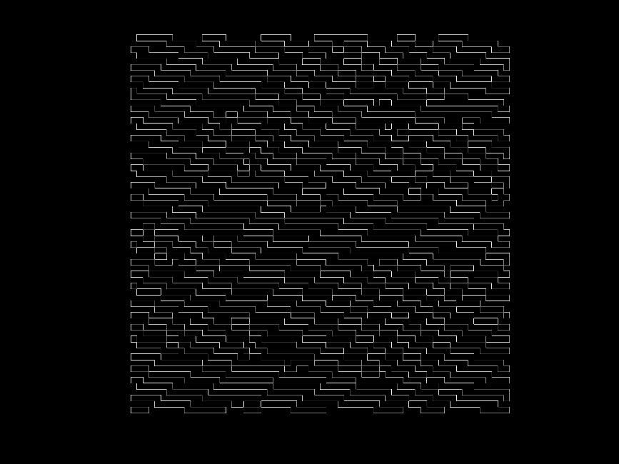
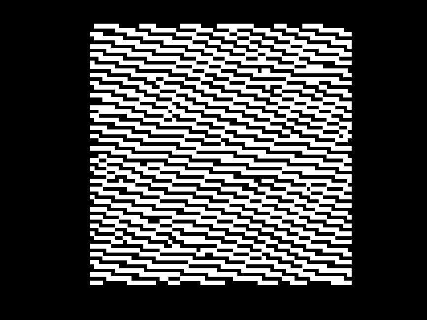
9 Simplest approach: use regular, 1-D grating Detection of collapsed nanochannels: promising 9
 100 µm")
 angle in far field (radians) Irrelevant variations may complicate interpretation Need a")
10 Simplest approach: use regular, 1-D grating Incomplete embossing: changes in topography cause non-intuitive changes in envelope Topography of one grating period s cross-section (µm) 100 µm interpolated Intensity of observed diffraction orders (a.u.) angle in far field (radians) Irrelevant variations may complicate interpretation Need a calibrated sensor and controlled environment 10


11 Holographic elements instead of regular gratings? Holograms redistribute energy in far-field, and provide more information within a given angular range. Could design holograms to reduce interpretation of diffraction patterns to intensity comparisons only Can we design patterns to identify specific defects? Simple grating Δ diffract 0 λ/δ sin θ Hologram, pixel size Δ NΔ diffract 0 pitch λ/nδ λ/δ sin θ 11
12 Two approaches using holograms 1. Reference holograms modulate light passing through a simple part containing an embossed grating 2. Hologram built into the part itself 12

![with hologram: Reference hologram h[m, n] H[u,](/docs-images/87/95235935/images/13-1.jpg "v] H[u N/2, v] Grating: pitch = 2Δ, phase-relief")
![= π rad h[m, n] Different grating phase-reliefs](/docs-images/87/95235935/images/13-6.jpg "produce a weighted superposition of these two")
13 Idea 1: measuring the depths of nanochannels Quadrant-swapping effect of grating in contact with hologram: Reference hologram h[m, n] H[u, v] H[u N/2, v] Grating: pitch = 2Δ, phase-relief = π rad h[m, n] Different grating phase-reliefs produce a weighted superposition of these two cases 13
 = 0 π/4 π/2")
δz/λ0 Set of 9 reference")
![holograms hk[m, n] illuminated](/docs-images/87/95235935/images/14-6.jpg "together through part under")
14 Nanochannel depth-measurement scheme Δφ (mod 2π) = 0 π/4 π/2 3π/4 π 5π/4 3π/2 7π/4 Δφ = 2π(n n0)δz/λ0 Set of 9 reference holograms hk[m, n] illuminated together through part under test 14


15 Nanochannel depth-measurement scheme 15
16 Nanochannel depth-measurement: limitations Resolution for red light and PMMA ~ 200 nm with present hologram designs Angular alignment sensitivity is severe Linear offset introduces ambiguity if phase-relief can be greater than π rad. Requires physical contact between holograms and part under test Always ambiguous for gratings with a phase-relief of larger than 2π rad; yet we will sometimes need to measure channels that are many λ deep. 16


17 Idea 2: measuring incomplete feature formation Narrower features harder to fill than wider, when polymer in a rubbery regime 3 µm pattern-dependency test stamp measured topography, PMMA, 110 C, 8 MPa Can exploit this behaviour to detect excessively low embossing pressure 17


18 Topography of pixel determines intensity envelope 1. Pixel shapes depend on stamp design and embossing conditions 2. Fourier transform 2. Fourier transform 3. Multiply 4. Focus on a particular part of the Fraunhofer plane 18


19 Two pixel designs developed to give substantial and opposite changes in envelope intensity Pixel shape 1: easier to fill Embossed topographies 5 MPa Intensity envelopes stamp recess 3 MPa Pixel 1, 3 MPa Pixel 2, 5 MPa Pixel 1, 5 MPa Pixel shape 2: harder to fill 5 MPa 3 MPa Pixel 2, 3 MPa Flat square pixel Position in envelope region of interest (multiples of sin θ = λ/nδ) 19


20 Two holograms and corresponding pixel designs respond to varying embossing pressure 20
21 Idea 2: challenges and opportunities Requires definition of sub-pixel features: stamp fabrication expensive? Could enhance information provided by designing holograms with richer, graded-intensity patterns If multi-level stamps are available, could have greater control of pressure-sensitivity 21
22 Summary and future directions Overall idea: reduce interpretation of diffraction patterns to a series of binary intensity comparisons Idea 1: nanochannel depth measurement well defined output requires contact and alignment Idea 2: incomplete filling detection for microchannels design approach demonstrated uses optimised pixel and hologram designs a promising stand-alone metrology tool needs fabricating and testing need to check insensitivity to other processing defects Future directions layer-layer alignment global distortion check diffractive components in fluidic devices 22
23 Acknowledgements Matthew Dirckx, David Hardt, George Barbastathis, Yee Cheong Lam, Nici Ames and Lallit Anand The Singapore-MIT Alliance 23
Diffraction-based Approaches to the In-situ Measurement of Dimensional Variations in Components Produced by Thermoplastic Micro- and Nano-embossing
 Diffraction-based Approaches to the In-situ Measurement of Dimensional Variations in Components Produced by Thermoplastic Micro- and Nano-embossing Hayden K. Taylor and Duane. Boning Microsystems Technology
Tutorial Solutions. 10 Holographic Applications Holographic Zone-Plate
 10 Holographic Applications 10.1 Holographic Zone-Plate Tutorial Solutions Show that if the intensity pattern for on on-axis holographic lens is recorded in lithographic film, then a one-plate results.
MEMS SENSOR FOR MEMS METROLOGY
 MEMS SENSOR FOR MEMS METROLOGY IAB Presentation Byungki Kim, H Ali Razavi, F. Levent Degertekin, Thomas R. Kurfess 9/24/24 OUTLINE INTRODUCTION Motivation Contact/Noncontact measurement Optical interferometer
Optics Vac Work MT 2008
 Optics Vac Work MT 2008 1. Explain what is meant by the Fraunhofer condition for diffraction. [4] An aperture lies in the plane z = 0 and has amplitude transmission function T(y) independent of x. It is
Problem Solving 10: Double-Slit Interference
 MASSACHUSETTS INSTITUTE OF TECHNOLOGY Department of hysics roblem Solving 10: Double-Slit Interference OBJECTIVES 1. To introduce the concept of interference. 2. To find the conditions for constructive
Interference. Electric fields from two different sources at a single location add together. The same is true for magnetic fields at a single location.
 Interference Electric fields from two different sources at a single location add together. The same is true for magnetic fields at a single location. Thus, interacting electromagnetic waves also add together.
Control of Light. Emmett Ientilucci Digital Imaging and Remote Sensing Laboratory Chester F. Carlson Center for Imaging Science 8 May 2007
 Control of Light Emmett Ientilucci Digital Imaging and Remote Sensing Laboratory Chester F. Carlson Center for Imaging Science 8 May 007 Spectro-radiometry Spectral Considerations Chromatic dispersion
Measurement of Highly Parabolic Mirror using Computer Generated Hologram
 Measurement of Highly Parabolic Mirror using Computer Generated Hologram Taehee Kim a, James H. Burge b, Yunwoo Lee c a Digital Media R&D Center, SAMSUNG Electronics Co., Ltd., Suwon city, Kyungki-do,
4D IMAGING AT YOUR FINGERTIPS Real-time, Portable, High-Resolution Solutions for your Quality Control Needs
 STDO Dynamic 3D 4D Imaging Microscopy Instrument Systems 4D IMAGING AT YOUR FINGERTIPS Real-time, Portable, High-Resolution Solutions for your Quality Control Needs STDO-HOLO Overview: STDO-HOLO enables
Digitalna Holografija i Primjene
 Digitalna Holografija i Primjene Hrvoje Skenderović Institut za fiziku 5. PIF Radionica, IRB, 16.12.2014. Holography Dennis Gabor invented holography in 1948 as a method for recording and reconstructing
Lecture 39. Chapter 37 Diffraction
 Lecture 39 Chapter 37 Diffraction Interference Review Combining waves from small number of coherent sources double-slit experiment with slit width much smaller than wavelength of the light Diffraction
PHYSICS. Chapter 33 Lecture FOR SCIENTISTS AND ENGINEERS A STRATEGIC APPROACH 4/E RANDALL D. KNIGHT
 PHYSICS FOR SCIENTISTS AND ENGINEERS A STRATEGIC APPROACH 4/E Chapter 33 Lecture RANDALL D. KNIGHT Chapter 33 Wave Optics IN THIS CHAPTER, you will learn about and apply the wave model of light. Slide
Supplementary Figure 1 Optimum transmissive mask design for shaping an incident light to a desired
 Supplementary Figure 1 Optimum transmissive mask design for shaping an incident light to a desired tangential form. (a) The light from the sources and scatterers in the half space (1) passes through the
Part 7 Holography. Basic Hologram Setup
 Part 7 Holography Basic Holographic Technique Light Sources Recording Materials Holographic Non-Destructive Testing Real-Time Double-Exposure Time-Average 2000 - James C. Wyant Part 7 Page 1 of 28 Basic
G3 TWO-SOURCE INTERFERENCE OF WAVES
 G3 TWO-SOURCE INTERFERENCE OF WAVES G4 DIFFRACTION GRATINGS HW/Study Packet Required: READ Tsokos, pp 624-631 SL/HL Supplemental: Hamper, pp 424-428 DO Questions pp 631-632 #1,3,8,9,10 REMEMBER TO. Work
Coupling of surface roughness to the performance of computer-generated holograms
 Coupling of surface roughness to the performance of computer-generated holograms Ping Zhou* and Jim Burge College of Optical Sciences, University of Arizona, Tucson, Arizona 85721, USA *Corresponding author:
Experiment 8 Wave Optics
 Physics 263 Experiment 8 Wave Optics In this laboratory, we will perform two experiments on wave optics. 1 Double Slit Interference In two-slit interference, light falls on an opaque screen with two closely
16. Holography. Dennis Gabor (1947) Nobel Prize in Physics (1971)
 Nobel Prize in Physics (1971)") 16. Holography Dennis Gabor (1947) Nobel Prize in Physics (1971) Photography Records intensity distribution of light. Does not record direction. Two-dimensional image. Holography = whole + writing Records
16. Holography Dennis Gabor (1947) Nobel Prize in Physics (1971) Photography Records intensity distribution of light. Does not record direction. Two-dimensional image. Holography = whole + writing Records
COHERENCE AND INTERFERENCE
 COHERENCE AND INTERFERENCE - An interference experiment makes use of coherent waves. The phase shift (Δφ tot ) between the two coherent waves that interfere at any point of screen (where one observes the
Chapter 36. Diffraction. Dr. Armen Kocharian
 Chapter 36 Diffraction Dr. Armen Kocharian Diffraction Light of wavelength comparable to or larger than the width of a slit spreads out in all forward directions upon passing through the slit This phenomena
Sensor based adaptive laser micromachining using ultrashort pulse lasers for zero-failure manufacturing
 Sensor based adaptive laser micromachining using ultrashort pulse lasers for zero-failure manufacturing Fraunhofer Institute for Production Technology, Aachen M. Sc. Guilherme Mallmann Prof. Dr.-Ing. Robert
University Physics (Prof. David Flory) Chapt_37 Monday, August 06, 2007
 Chapt_37 Monday, August 06, 2007") Name: Date: 1. If we increase the wavelength of the light used to form a double-slit diffraction pattern: A) the width of the central diffraction peak increases and the number of bright fringes within
Name: Date: 1. If we increase the wavelength of the light used to form a double-slit diffraction pattern: A) the width of the central diffraction peak increases and the number of bright fringes within
d has a relationship with ψ
 Principle of X-Ray Stress Analysis Metallic materials consist of innumerable crystal grains. Each grain usually faces in a random direction. When stress is applied on such materials, the interatomic distance
Metrology of Microfluidic Devices: A Review
 Metrology of Microfluidic Devices: A Review ICOMM 2006 No.: 49 Vijay Shilpiekandula 1, Daniel J. Burns 1, Khalid El Rifai 1, Kamal Youcef-Toumi 1, Li Shiguang 2, Ivan Reading 2, Soon Fatt Yoon 3 1 Dept.
1 Laboratory #4: Division-of-Wavefront Interference
 1051-455-0073, Physical Optics 1 Laboratory #4: Division-of-Wavefront Interference 1.1 Theory Recent labs on optical imaging systems have used the concept of light as a ray in goemetrical optics to model
Diffraction and Interference of Plane Light Waves
 PHY 92 Diffraction and Interference of Plane Light Waves Diffraction and Interference of Plane Light Waves Introduction In this experiment you will become familiar with diffraction patterns created when
Chapter 37. Wave Optics
 Chapter 37 Wave Optics Wave Optics Wave optics is a study concerned with phenomena that cannot be adequately explained by geometric (ray) optics. Sometimes called physical optics These phenomena include:
Optical Diffraction and Interference using Single Photon Counting
 Optical Diffraction and Interference using Single Photon Counting Optical Diffraction and Interference using Single Photon Counting In this experiment the wave and quantum properties of light can be studied
Introduction to Diffraction Gratings
 Introduction to Diffraction Diffraction (Ruled and Holographic) Diffraction gratings can be divided into two basic categories: holographic and ruled. A ruled grating is produced by physically forming grooves
High spatial resolution measurement of volume holographic gratings
 High spatial resolution measurement of volume holographic gratings Gregory J. Steckman, Frank Havermeyer Ondax, Inc., 8 E. Duarte Rd., Monrovia, CA, USA 9116 ABSTRACT The conventional approach for measuring
LECTURE 14 PHASORS & GRATINGS. Instructor: Kazumi Tolich
 LECTURE 14 PHASORS & GRATINGS Instructor: Kazumi Tolich Lecture 14 2 Reading chapter 33-5 & 33-8 Phasors n Addition of two harmonic waves n Interference pattern from multiple sources n Single slit diffraction
STEEL SURFACE CHARACTERIZATION USING 3D PROFILOMETRY
 STEEL SURFACE CHARACTERIZATION USING 3D PROFILOMETRY Prepared by Andrea Novitsky 6 Morgan, Ste156, Irvine CA 92618 P: 949.461.9292 F: 949.461.9232 nanovea.com Today's standard for tomorrow's materials.
Hyperspectral interferometry for single-shot absolute measurement of 3-D shape and displacement fields
 EPJ Web of Conferences 6, 6 10007 (2010) DOI:10.1051/epjconf/20100610007 Owned by the authors, published by EDP Sciences, 2010 Hyperspectral interferometry for single-shot absolute measurement of 3-D shape
Three-dimensional imaging of 30-nm nanospheres using immersion interferometric lithography
 Three-dimensional imaging of 30-nm nanospheres using immersion interferometric lithography Jianming Zhou *, Yongfa Fan, Bruce W. Smith Microelectronics Engineering Department, Rochester Institute of Technology,
Development of EUV-Scatterometry for CD Characterization of Masks. Frank Scholze, Gerhard Ulm Physikalisch-Technische Bundesanstalt, Berlin, Germany
 Development of EUV-Scatterometry for CD Characterization of Masks PB Frank Scholze, Gerhard Ulm Physikalisch-Technische Bundesanstalt, Berlin, Germany Jan Perlich, Frank-Michael Kamm, Jenspeter Rau nfineon
Chapter 4 - Diffraction
 Diffraction is the phenomenon that occurs when a wave interacts with an obstacle. David J. Starling Penn State Hazleton PHYS 214 When a wave interacts with an obstacle, the waves spread out and interfere.
Chapter 37. Interference of Light Waves
 Chapter 37 Interference of Light Waves Wave Optics Wave optics is a study concerned with phenomena that cannot be adequately explained by geometric (ray) optics These phenomena include: Interference Diffraction
SOLAR CELL SURFACE INSPECTION USING 3D PROFILOMETRY
 SOLAR CELL SURFACE INSPECTION USING 3D PROFILOMETRY Prepared by Benjamin Mell 6 Morgan, Ste16, Irvine CA 92618 P: 949.461.9292 F: 949.461.9232 nanovea.com Today's standard for tomorrow's materials. 21
O-RING SURFACE INSPECTION USING 3D PROFILOMETRY
 O-RING SURFACE INSPECTION USING 3D PROFILOMETRY Prepared by Jorge Ramirez 6 Morgan, Ste156, Irvine CA 92618 P: 949.461.9292 F: 949.461.9232 nanovea.com Today's standard for tomorrow's materials. 2010 NANOVEA
Holography & Coherence For Holography need coherent beams Two waves coherent if fixed phase relationship between them for some period of time
 Holography & Coherence For Holography need coherent beams Two waves coherent if fixed phase relationship between them for some period of time Coherence Coherence appear in two ways Spatial Coherence Waves
SURFACE BOUNDARY MEASUREMENT USING 3D PROFILOMETRY
 SURFACE BOUNDARY MEASUREMENT USING 3D PROFILOMETRY Prepared by Craig Leising 6 Morgan, Ste156, Irvine CA 92618 P: 949.461.9292 F: 949.461.9232 nanovea.com Today's standard for tomorrow's materials. 2013
WARPAGE MEASUREMENT OF PCB USING 3D PROFILOMETRY
 WARPAGE MEASUREMENT OF PCB USING 3D PROFILOMETRY Prepared by Craig Leising 6 Morgan, Ste156, Irvine CA 92618 P: 949.461.9292 F: 949.461.9232 nanovea.com Today's standard for tomorrow's materials. 2010
Lecture 6: Waves Review and Examples PLEASE REVIEW ON YOUR OWN. Lecture 6, p. 1
 Lecture 6: Waves Review and Examples PLEASE REVEW ON YOUR OWN Lecture 6, p. 1 Single-Slit Slit Diffraction (from L4) Slit of width a. Where are the minima? Use Huygens principle: treat each point across
TISSUE SURFACE TOPOGRAPHY USING 3D PRFILOMETRY
 TISSUE SURFACE TOPOGRAPHY USING 3D PRFILOMETRY Prepared by Craig Leising 6 Morgan, Ste156, Irvine CA 92618 P: 949.461.9292 F: 949.461.9232 nanovea.com Today's standard for tomorrow's materials. 2011 NANOVEA
No Brain Too Small PHYSICS
 Level 3 Physics: Demonstrate understanding of Waves Waves Behaviour - Answers In 03, AS 953 replaced AS 9050. The Mess that is NCEA Assessment Schedules. In AS 9050 there was an Evidence column with the
CHARACTERIZATION OF FISH SCALE USING 3D PROFILOMETRY
 CHARACTERIZATION OF FISH SCALE USING 3D PROFILOMETRY 2 4 6 8 1 mm 1 2 3 4 5 6 7 8 mm Prepared by Andrea Novitsky 6 Morgan, Ste156, Irvine CA 92618 P: 949.461.9292 F: 949.461.9232 nanovea.com Today's standard
Using a multipoint interferometer to measure the orbital angular momentum of light
 CHAPTER 3 Using a multipoint interferometer to measure the orbital angular momentum of light Recently it was shown that the orbital angular momentum of light can be measured using a multipoint interferometer,
Limits of computational white-light holography
 Journal of Physics: Conference Series Limits of computational white-light holography To cite this article: Sebastian Mader et al 2013 J. Phys.: Conf. Ser. 415 012046 View the article online for updates
Single Slit Diffraction
 Name: Date: PC1142 Physics II Single Slit Diffraction 5 Laboratory Worksheet Part A: Qualitative Observation of Single Slit Diffraction Pattern L = a 2y 0.20 mm 0.02 mm Data Table 1 Question A-1: Describe
3D Holographic Lithography
 3D Holographic Lithography Luke Seed, Gavin Williams, Jesus Toriz-Garcia Department of Electronic and Electrical Engineering University of Sheffield Richard McWilliam, Alan Purvis, Richard Curry School
Interference of Light
 Lecture 22 Chapter 22 Physics II Wave Optics: Interference of Light Course website: http://faculty.uml.edu/andriy_danylov/teaching/physicsii Wave Motion Interference Models of Light (Water waves are Easy
Roughness parameters and surface deformation measured by "Coherence Radar" P. Ettl, B. Schmidt, M. Schenk, I. Laszlo, G. Häusler
 Roughness parameters and surface deformation measured by "Coherence Radar" P. Ettl, B. Schmidt, M. Schenk, I. Laszlo, G. Häusler University of Erlangen, Chair for Optics Staudtstr. 7/B2, 91058 Erlangen,
SURFACE FINISH INSPECTION OF WOOD USING 3D PROFILOMETRY
 SURFACE FINISH INSPECTION OF WOOD USING 3D PROFILOMETRY Prepared by Duanjie Li & Craig Leising 6 Morgan, Ste156, Irvine CA 92618 P: 949.461.9292 F: 949.461.9232 nanovea.com Today's standard for tomorrow's
Techniques of Noninvasive Optical Tomographic Imaging
 Techniques of Noninvasive Optical Tomographic Imaging Joseph Rosen*, David Abookasis and Mark Gokhler Ben-Gurion University of the Negev Department of Electrical and Computer Engineering P. O. Box 653,
Chapter 8: Physical Optics
 Chapter 8: Physical Optics Whether light is a particle or a wave had puzzled physicists for centuries. In this chapter, we only analyze light as a wave using basic optical concepts such as interference
Chapter 7. Widely Tunable Monolithic Laser Diodes
 Chapter 7 Widely Tunable Monolithic Laser Diodes We have seen in Chapters 4 and 5 that the continuous tuning range λ is limited by λ/λ n/n g, where n is the index change and n g the group index of the
Physical & Electromagnetic Optics: Diffraction Gratings
 31/05/2018 Physical & Electromagnetic Optics: Diffraction Gratings Optical Engineering Prof. Elias N. Glytsis School of Electrical & Computer Engineering National Technical University of Athens Multiple
Chapter 38 Wave Optics (II)
") Chapter 38 Wave Optics (II) Initiation: Young s ideas on light were daring and imaginative, but he did not provide rigorous mathematical theory and, more importantly, he is arrogant. Progress: Fresnel,
Chapter 38 Wave Optics (II) Initiation: Young s ideas on light were daring and imaginative, but he did not provide rigorous mathematical theory and, more importantly, he is arrogant. Progress: Fresnel,
MEASUREMENT OF PATTERNED WAFER SURFACE DEFECTS USING ANNULAR EVANESCENT LIGHT ILLUMINATION METHOD
 XVIII IMEKO WORLD CONGRESS Metrology for a Sustainable Development September, 17 22, 26, Rio de Janeiro, Brazil MEASUREMENT OF PATTERNED WAFER SURFACE DEFECTS USING ANNULAR EVANESCENT LIGHT ILLUMINATION
Unit I Light and Optics
 Unit I Light and Optics Outline By the time you finish this, you should understand the following aspects of our experiment: 1) Why you produce a grating pattern when you cross two laser beams. 2) What
Determining Wave-Optics Mesh Parameters for Modeling Complex Systems of Simple Optics
 Determining Wave-Optics Mesh Parameters for Modeling Complex Systems of Simple Optics Dr. Justin D. Mansell, Steve Coy, Liyang Xu, Anthony Seward, and Robert Praus MZA Associates Corporation Outline Introduction
To see how a sharp edge or an aperture affect light. To analyze single-slit diffraction and calculate the intensity of the light
 Diffraction Goals for lecture To see how a sharp edge or an aperture affect light To analyze single-slit diffraction and calculate the intensity of the light To investigate the effect on light of many
AP Physics Problems -- Waves and Light
 AP Physics Problems -- Waves and Light 1. 1975-4 (Physical Optics) a. Light of a single wavelength is incident on a single slit of width w. (w is a few wavelengths.) Sketch a graph of the intensity as
Supplementary Figure 1: Schematic of the nanorod-scattered wave along the +z. direction.
 Supplementary Figure 1: Schematic of the nanorod-scattered wave along the +z direction. Supplementary Figure 2: The nanorod functions as a half-wave plate. The fast axis of the waveplate is parallel to
MEASUREMENT OF THE WAVELENGTH WITH APPLICATION OF A DIFFRACTION GRATING AND A SPECTROMETER
 Warsaw University of Technology Faculty of Physics Physics Laboratory I P Irma Śledzińska 4 MEASUREMENT OF THE WAVELENGTH WITH APPLICATION OF A DIFFRACTION GRATING AND A SPECTROMETER 1. Fundamentals Electromagnetic
Formulas of possible interest
 Name: PHYS 3410/6750: Modern Optics Final Exam Thursday 15 December 2011 Prof. Bolton No books, calculators, notes, etc. Formulas of possible interest I = ɛ 0 c E 2 T = 1 2 ɛ 0cE 2 0 E γ = hν γ n = c/v
Determining Wave-Optics Mesh Parameters for Complex Optical Systems
 Copyright 007 Society of Photo-Optical Instrumentation Engineers. This paper was published in SPIE Proc. Vol. 6675-7 and is made available as an electronic reprint with permission of SPIE. One print or
SCDI for EUV photomask metrology RESCAN - Reflective EUV Mask Scanning Lensless Imaging Tool
 EUV Litho Workshop 2017 WIR SCHAFFEN WISSEN HEUTE FÜR MORGEN P. Helfenstein a, I. Mochi a, R. Rajendran a, S. Fernandez a, S. Yoshitake b, Y. Ekinci a a Paul Scherrer Institut, Switzerland b NuFlare Technology
Information virtual indicator with combination of diffractive optical elements
 Journal of Physics: Conference Series PAPER OPEN ACCESS Information virtual indicator with combination of diffractive optical elements To cite this article: Y A Grad et al 2016 J. Phys.: Conf. Ser. 737
E x Direction of Propagation. y B y
 x E x Direction of Propagation k z z y B y An electromagnetic wave is a travelling wave which has time varying electric and magnetic fields which are perpendicular to each other and the direction of propagation,
No Brain Too Small PHYSICS
 Level 3 Physics: Demonstrate understanding of Waves Waves Behaviour - Answers In 203, AS 9523 replaced AS 90520. The Mess that is NCEA Assessment Schedules. In AS 90520 there was an Evidence column with
Diffraction and Interference
 Diffraction and Interference Kyle Weigand, Mark Hillstrom Abstract: We measure the patterns produced by a CW laser near 650 nm passing through one and two slit apertures with a detector mounted on a linear
29. Diffraction of waves
 29. Diffraction of waves Light bends! Diffraction assumptions The Kirchhoff diffraction integral Fresnel Diffraction diffraction from a slit Diffraction Light does not always travel in a straight line.
SIMULATION AND VISUALIZATION IN THE EDUCATION OF COHERENT OPTICS
 SIMULATION AND VISUALIZATION IN THE EDUCATION OF COHERENT OPTICS J. KORNIS, P. PACHER Department of Physics Technical University of Budapest H-1111 Budafoki út 8., Hungary e-mail: kornis@phy.bme.hu, pacher@phy.bme.hu
Manual Diffraction. Manual remote experiment Project e-xperimenteren+ J. Snellenburg, J.M.Mulder
 Manual remote experiment Project e-xperimenteren+ J. Snellenburg, J.M.Mulder 30-01-006 Colofon Manual diffraction Manual remote experiment Project e-xperimenteren+ Stichting Digitale Universiteit Oudenoord
Interference of Light
 Lecture 23 Chapter 22 Physics II Wave Optics: Interference of Light Course website: http://faculty.uml.edu/andriy_danylov/teaching/physicsii Lecture Capture: http://echo360.uml.edu/danylov201415/physics2spring.html
Second Year Optics 2017 Problem Set 1
 Second Year Optics 2017 Problem Set 1 Q1 (Revision of first year material): Two long slits of negligible width, separated by a distance d are illuminated by monochromatic light of wavelength λ from a point
MICRO SCRATCH DEPTH USING 3D PROFILOMETRY
 MICRO SCRATCH DEPTH USING 3D PROFILOMETRY Prepared by Jorge Ramirez 6 Morgan, Ste156, Irvine CA 92618 P: 949.461.9292 F: 949.461.9232 nanovea.com Today's standard for tomorrow's materials. 2012 NANOVEA
14 Chapter. Interference and Diffraction
 14 Chapter Interference and Diffraction 14.1 Superposition of Waves... 14-14.1.1 Interference Conditions for Light Sources... 14-4 14. Young s Double-Slit Experiment... 14-4 Example 14.1: Double-Slit Experiment...
Overview of Active Vision Techniques
 SIGGRAPH 99 Course on 3D Photography Overview of Active Vision Techniques Brian Curless University of Washington Overview Introduction Active vision techniques Imaging radar Triangulation Moire Active
Optical Topography Measurement of Patterned Wafers
 Optical Topography Measurement of Patterned Wafers Xavier Colonna de Lega and Peter de Groot Zygo Corporation, Laurel Brook Road, Middlefield CT 6455, USA xcolonna@zygo.com Abstract. We model the measurement
College Physics B - PHY2054C
 Young College - PHY2054C Wave Optics: 10/29/2014 My Office Hours: Tuesday 10:00 AM - Noon 206 Keen Building Outline Young 1 2 3 Young 4 5 Assume a thin soap film rests on a flat glass surface. Young Young
Optical simulations within and beyond the paraxial limit
 Optical simulations within and beyond the paraxial limit Daniel Brown, Charlotte Bond and Andreas Freise University of Birmingham 1 Simulating realistic optics We need to know how to accurately calculate
WAVE SUPERPOSITION. Challenging MCQ questions by The Physics Cafe. Compiled and selected by The Physics Cafe
 WVE SUPERPOSITION hallenging MQ questions by The Physics afe ompiled and selected by The Physics afe 1 Two coherent monochromatic waves of equal amplitude are brought together to form an interference pattern
Wavelength scanning interferometry for measuring transparent films of the fusion targets
 Wavelength scanning interferometry for measuring transparent films of the fusion targets F. Gao *, X. Jiang, H. Muhamedsalih and H. Martin Centre for precision Technologies, University of Huddersfield,
Holography. How is that different than photography? How is it accomplished? Amplitude & Phase
 Holography 1948: Dennis Gabor proposes lensless imaging: wavefront reconstruction. Calls it total recording or Holo gram Concept: record and recreate wavefront incident on film. Amplitude & Phase How is
Lecture 4. Physics 1502: Lecture 35 Today s Agenda. Homework 09: Wednesday December 9
 Physics 1502: Lecture 35 Today s Agenda Announcements: Midterm 2: graded soon» solutions Homework 09: Wednesday December 9 Optics Diffraction» Introduction to diffraction» Diffraction from narrow slits»
White-light interference microscopy: minimization of spurious diffraction effects by geometric phase-shifting
 White-light interference microscopy: minimization of spurious diffraction effects by geometric phase-shifting Maitreyee Roy 1, *, Joanna Schmit 2 and Parameswaran Hariharan 1 1 School of Physics, University
LIGHT SCATTERING THEORY
 LIGHT SCATTERING THEORY Laser Diffraction (Static Light Scattering) When a Light beam Strikes a Particle Some of the light is: Diffracted Reflected Refracted Absorbed and Reradiated Reflected Refracted
MACHINING SURFACE FINISH QUALITY USING 3D PROFILOMETRY
 MACHINING SURFACE FINISH QUALITY USING 3D PROFILOMETRY Prepared by Duanjie Li, PhD Morgan, Ste1, Irvine CA 91 P: 99.1.99 F: 99.1.93 nanovea.com Today's standard for tomorrow's materials. 1 NANOVEA INTRODUCTION
University of Huddersfield Repository
 University of Huddersfield Repository Muhamedsalih, Hussam, Jiang, Xiang and Gao, F. Comparison of fast Fourier transform and convolution in wavelength scanning interferometry Original Citation Muhamedsalih,
PHYS 450 Fall semester Lecture 08: Young s Double Slit. Ron Reifenberger Birck Nanotechnology Center Purdue University
 /4/6 PHYS 45 Fall semester 6 Lecture 8: Young s Double Slit Ron Reifenberger Birck Nanotechnolog Center Purdue Universit Lecture 8 Young s Double Slit Experiment 83 ( double path genre of experiments)
Transmission Electron Microscopy 2. Scattering and Diffraction
 Transmission Electron Microscopy 2. Scattering and Diffraction EMA 6518 Spring 2007 01/07 Outline Why are we interested in electron scattering? Terminology of scattering The characteristics of electron
Fourier, Fresnel and Image CGHs of three-dimensional objects observed from many different projections
 Fourier, Fresnel and Image CGHs of three-dimensional objects observed from many different projections David Abookasis and Joseph Rosen Ben-Gurion University of the Negev Department of Electrical and Computer
ratio of the volume under the 2D MTF of a lens to the volume under the 2D MTF of a diffraction limited
 SUPPLEMENTARY FIGURES.9 Strehl ratio (a.u.).5 Singlet Doublet 2 Incident angle (degree) 3 Supplementary Figure. Strehl ratio of the singlet and doublet metasurface lenses. Strehl ratio is the ratio of
Full-field optical methods for mechanical engineering: essential concepts to find one way
 Full-field optical methods for mechanical engineering: essential concepts to find one way Yves Surrel Techlab September 2004 1 Contents 1 Introduction 3 2 White light methods 4 2.1 Random encoding............................................
Innovations in beam shaping & illumination applications
 Innovations in beam shaping & illumination applications David L. Shealy Department of Physics University of Alabama at Birmingham E-mail: dls@uab.edu Innovation Novelty The introduction of something new
Class 33: Outline. Hour 1: Interference. Hour 2: Experiment 13: Interference P33-
 Class 33: Outline Hour 1: Interference Hour 2: Experiment 13: Interference P33-1 Last time: Microwaves (mw) c f = 2 10 9 Hz λ = = 15cm mw mw f This time: Visible (red) light: c = 4.6 10 = = 6.54 10 f 14
Diffraction and Interference of Plane Light Waves
 1 Diffraction and Interference of Plane Light Waves Introduction In this experiment you will become familiar with diffraction patterns created when a beam of light scatters from objects placed in its path.
DENTAL WEAR SURFACE USING 3D PROFILOMETRY
 DENTAL WEAR SURFACE USING 3D PROFILOMETRY Prepared by Ali Mansouri 6 Morgan, Ste156, Irvine CA 92618 P: 949.461.9292 F: 949.461.9232 nanovea.com Today's standard for tomorrow's materials. 2016 NANOVEA