REAL TIME DIGITAL SIGNAL PROCESSING
|
|
|
- Agnes Lambert
- 5 years ago
- Views:
Transcription

1 REAL TIME DIGITAL SIGNAL PROCESSING UTN-FRBA 2011 Eng. Julian Bruno
2 Architecture Introduction to the Blackfin Processor


3 Core Architecture BF53X Control Units Program Sequencer Conditional jumps and subroutine calls Nested zero-overhead looping Code density
4 Control Units BF53X Program Sequencing Interrupt Processing modules Program Flow Control External Event Management Specific interrupt sources

 INSTRUCTION ADDRESS BUS (IAB)")
5 Program Sequencing and Interrupt Processing Block Diagram PERIPHERAL ACCESS BUS (PAB) REGISTER ACCESS BUS (RAB) INSTRUCTION ADDRESS BUS (IAB) INSTRUCTION DATA BUS (IDB)
6 Program Flow Program flow in the chip is mostly linear The processor executing program instructions sequentially The linear flow varies occasionally when the program uses nonsequential program structures, such as: Loops. Subroutines. Jumps. Interrupts and Exceptions. Idle.

7 Program Flow Variations

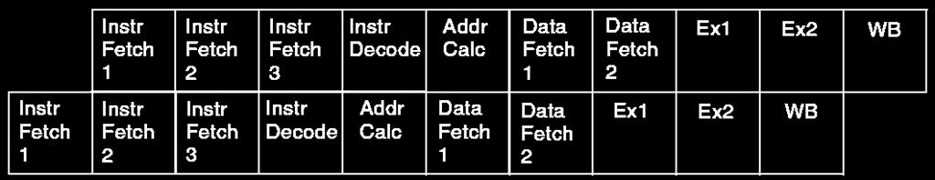
8 Instruction Pipeline The program sequencer determines the next instruction address by examining both the current instruction being executed and the current state of the processor. The processor has a ten-stage instruction pipeline The instructions can be 16, 32, or 64 bits wide Multi-issue instructions are 64 bits in length and consist of one 32-bit instruction and two 16-bit instructions
9 Instruction Pipeline (II) Pipeline Stage Instruction Fetch 1 (IF1) Instruction Fetch 2 (IF2) Instruction Fetch 3 (IF3) Instruction Decode (DEC) Address Calculation (AC) Data Fetch 1 (DF1) Data Fetch 2 (DF2) Execute 1 (EX1) Execute 2 (EX2) Write Back (WB) Description Issue instruction address to IAB bus, start compare tag of instruction cache Wait for instruction data Read from IDB bus and align instruction Decode instructions Calculation of data addresses and branch target address Issue data address to DA0 and DA1 bus, start compare tag of data cache Read register files Read data from LD0 and LD1 bus, start multiply and video instructions Execute/Complete instructions (shift, add, logic, etc.) Writes back to register files, SD bus, and pointer updates (also referred to as the commit stage)


10 Instruction Pipeline (III)
11 Instruction Pipeline (IV) Inst. #1 Inst. #2 Inst. #3 Inst. #4 Inst. #5 Inst. #6 Inst. #7 Inst. #8 Inst. #9 IF1 IF2 IF3 DE AC EX EX EX EX WB IF1 IF2 IF3 DE AC EX EX EX EX WB IF1 IF2 IF3 DE AC EX EX EX EX WB IF1 IF2 IF3 DE AC EX EX EX EX IF1 IF2 IF3 DE AC EX EX EX IF1 IF2 IF3 DE AC EX EX IF1 IF2 IF3 DE AC EX IF1 IF2 IF3 DE AC IF1 IF2 IF3 DE Inst. #10 IF1 IF2 IF3 #1 #2 #3 #4 #5 #6 #7 #8 #9 #10 Pipeline is full and completes one instruction per cycle cycle
12 Branches A branch occurs when a JUMP or CALL instruction begins execution at a new location other than the next sequential address. The are five types of return instructions: RTS, RTI, RTX, RTN and RTE. Each return type has its own register for holding the return address. RETS, RETI, RETX, RETN and RETE.
13 Branches (II) The program sequencer can evaluate the CC status bit to decide whether to execute a branch. Conditional JUMP instructions use static branch prediction to reduce the branch latency caused by the length of the pipeline. Branches can be direct or indirect. A direct branch address is determined solely by the instruction word. JUMP 0x30; An indirect branch gets its address from the contents of a DAG register. JUMP(P3);
14 Branches (III) Direct Short and Long Jumps Direct Call Indirect Branch and Call PC-Relative Indirect Branch and Call Subroutines Condition Code Flag Branch Prediction
15 Direct Short and Long Jumps The target of the branch is: PC-relative address + Offset Short jump: The PC-relative offset is a 13-bit immediate value that must be a multiple of two Dynamic range of 4096 to bytes. JUMP.S 0xnnnn Long jump: The PC-relative offset for is a 25-bit immediate value that must also be a multiple of two. Dynamic range of 16,777,216 to +16,777,214 bytes. JUMP.L 0xnnnnnnn
16 Branches (III) Direct Short and Long Jumps Direct Call Indirect Branch and Call PC-Relative Indirect Branch and Call Subroutines Condition Code Flag Branch Prediction
17 Direct Call CALL instruction copies the address of the instruction which would have executed next into the RETS register. The direct CALL instruction has a 25-bit, PCrelative offset that must be a multiple of two. The 25-bit value gives an effective dynamic range of 16,777,216 to +16,777,214 bytes. A direct CALL instruction is always a 4-byte instruction.
18 Branches (III) Direct Short and Long Jumps Direct Call Indirect Branch and Call PC-Relative Indirect Branch and Call Subroutines Condition Code Flag Branch Prediction
19 Indirect Branch and Call The indirect instructions get their destination address from a data address generator (DAG) P-register. For the CALL instruction, the RETS register is loaded with the address of the instruction which would have executed. P4.H = HI(mytarget); P4.L = LO(mytarget); JUMP (P4);. mytarget: /* continue here */
20 Branches (III) Direct Short and Long Jumps Direct Call Indirect Branch and Call PC-Relative Indirect Branch and Call Subroutines Condition Code Flag Branch Prediction
21 PC-Relative Indirect Branch and Call The PC-relative indirect JUMP and CALL instructions use the contents of a P-register as an offset to the branch target. For the CALL instruction, the RETS register is loaded with the address of the instruction which would have executed next JUMP (PC + P3) ; CALL (PC + P0) ;
22 Branches (III) Direct Short and Long Jumps Direct Call Indirect Branch and Call PC-Relative Indirect Branch and Call Subroutines Condition Code Flag Branch Prediction
; /* pass a parameter */ CALL myfunction; /* continue here after the")
23 Subroutines Subroutines are code sequences that are invoked by a CALL instruction. leaf functions RETS = This address /* parent function */ R0 = 0x1234 (Z); /* pass a parameter */ CALL myfunction; /* continue here after the call */ [P0] = R0; /* save return value */ JUMP somewhereelse;
24 Subroutines - Leaf functions myfunction: /* subroutine label */ [--SP] = (R7:7, P5:5); /* multiple push instruction */ P5.H = HI(myregister); /* P5 used locally */ P5.L = LO(myregister); R7 = [P5]; /* R7 used locally */ R0 = R0 + R7; /* R0 user for parameter passing*/ (R7:7, P5:5) = [SP++]; /* multiple pop instruction */ RTS; /* return from subroutine */ myfunction.end: /* closing subroutine label */
; [--SP] = RETS; // save RETS onto stack CALL function_b; // call further subroutines CALL function_c; RETS = [SP++]; // restore RETS (R7:7, P5:5) = [SP++]; RTS; function_b: /*")
25 Subroutines - No leaf functions /* parent function */ CALL function_a; /* continue here after the call */ JUMP somewhereelse; RETS = This address RETS = This address RETS = This address function_a: [--SP] = (R7:7, P5:5); [--SP] = RETS; // save RETS onto stack CALL function_b; // call further subroutines CALL function_c; RETS = [SP++]; // restore RETS (R7:7, P5:5) = [SP++]; RTS; function_b: /* do something */ RTS; function_c: /* do something else */ RTS;
26 Managing the Stack

![R1; CALL _sub; R1 = [SP++]; // R1 = 4 R0](/docs-images/94/122075085/images/27-1.jpg "= [SP++]; // R0 = 2... _parent.")
![end: _sub: [--SP] = FP; FP = SP; [--SP]](/docs-images/94/122075085/images/27-2.jpg "= (R7:5); // save frame pointer // new")
![frame // multiple push R6 = [FP+4]; //](/docs-images/94/122075085/images/27-3.jpg "R6 = 3 R7 = [FP+8]; // R7 = 1 R5 = R6 +")

![R6 = 2 (R7:5) = [SP++]; // multiple pop](/docs-images/94/122075085/images/27-5.jpg "FP = [SP++]; RTS; _sub.")
27 Subroutines - Parameter Passing _parent:... R0 = 1; R1 = 3; [--SP] = R0; [--SP] = R1; CALL _sub; R1 = [SP++]; // R1 = 4 R0 = [SP++]; // R0 = 2... _parent.end: _sub: [--SP] = FP; FP = SP; [--SP] = (R7:5); // save frame pointer // new frame // multiple push R6 = [FP+4]; // R6 = 3 R7 = [FP+8]; // R7 = 1 R5 = R6 + R7; R6 = R6 - R7; // calculate anything [FP+4] = R5; // R5 = 4 [FP+8] = R6; // R6 = 2 (R7:5) = [SP++]; // multiple pop FP = [SP++]; RTS; _sub.end: // restore frame pointer
28 Subroutines Link and Unlink Code Sequencer LINK n; [--SP] = RETS; [--SP] = FP; FP = SP; SP += -n; _sub2: LINK 0; [--SP] = (R7:5); R6 = [FP+8]; //R6 = 3 R7 = [FP+12]; //R7 = 1 R5 = R6 + R7; R6 = R6 - R7; [FP+8] = R5; // R5 = 4 [FP+12] = R6; // R6 = 2 (R7:5) = [SP++]; UNLINK; RTS; _sub2.end: UNLINK SP = FP; FP = [SP++]; RETS = [SP++];.. _sub3: LINK 8; [--SP] = (R7:0, P5:0); R7 = 0 (Z); [FP-4] = R7; [FP-8] = R7;... (R7:0, P5:0) = [SP++]; UNLINK; RTS; _sub3.end:
![Subroutines Link and Unlink Code Sequencer LINK n; [--SP] = RETS; [--SP] = FP; FP = SP; SP += -n; _sub2: LINK 0; [--SP] = (R7:5); R6 = [FP+8]; //R6 = 3 R7 = [FP+12]; //R7 = 1 R5 = R6 + R7; R6 = R6 -](/docs-images/94/122075085/images/29-0.jpg "R7; [FP+8] = R5; // R5 = 4 [FP+12] = R6; // R6 = 2 (R7:5) = [SP++]; UNLINK; RTS; _sub2.end: UNLINK SP = FP; FP = [SP++]; RETS = [SP++];.")
29 Subroutines Link and Unlink Code Sequencer LINK n; [--SP] = RETS; [--SP] = FP; FP = SP; SP += -n; _sub2: LINK 0; [--SP] = (R7:5); R6 = [FP+8]; //R6 = 3 R7 = [FP+12]; //R7 = 1 R5 = R6 + R7; R6 = R6 - R7; [FP+8] = R5; // R5 = 4 [FP+12] = R6; // R6 = 2 (R7:5) = [SP++]; UNLINK; RTS; _sub2.end: UNLINK SP = FP; FP = [SP++]; RETS = [SP++];.. _sub3: LINK 8; [--SP] = (R7:0, P5:0); R7 = 0 (Z); [FP-4] = R7; [FP-8] = R7;... (R7:0, P5:0) = [SP++]; UNLINK; RTS; _sub3.end:
30 Branches (III) Direct Short and Long Jumps Direct Call Indirect Branch and Call PC-Relative Indirect Branch and Call Subroutines Condition Code Flag Branch Prediction
31 Condition Code (CC) Flag The CC flag can resolve the direction of a branch or the movement of a register. Conditional Branch Conditional Register Move IF CC JUMP dest; IF CC R0 = P0; There are eight ways of accessing the CC, and are used to control program flow.
32 Condition Code (CC) Flag (II) 1. A conditional branch is resolved by the value in CC. 2. A Data register value may be copied into CC, and the value in CC may be copied to a Data register. 3. The BITTST instruction accesses the CC flag. 4. A status flag may be copied into CC, and the value in CC may be copied to a status flag. 5. The CC flag bit may be set to the result of a Pointer register comparison. 6. The CC flag bit may be set to the result of a Data register comparison. 7. Some shifter instructions (rotate or BXOR) use CC as a portion of the shift operand/result. 8. Test and set instructions can set and clear the CC bit.
33 Branches (III) Direct Short and Long Jumps Direct Call Indirect Branch and Call PC-Relative Indirect Branch and Call Subroutines Condition Code Flag Branch Prediction
34 Branch Prediction Static branch strategy based on CC state. Predicted-not-taken (default) /* previous instructions */ If CC JUMP dest Predicted-taken (bp) /* previous instructions */ If CC JUMP dest (bp) /* following instructions */ /* following instructions */ dest: /* branch instructions */ dest: /* branch instructions */
35 Branch Prediction (II) Branch latency (CPU cycles) True Not-taken Taken Prediction Not-taken 0 8 Taken 8 4 Conclusion Typically, code analysis shows that a good default condition is to predict branch-taken for branches to a prior address (backwards branches), and to predict branch-not-taken for branches to subsequent addresses (forward branches).


36 Hardware Loops
37 Hardware Loops (II) The sequencer supports a mechanism of zerooverhead looping. The sequencer contains two loop units, each containing three registers: Loop Top register (LT0, LT1) Holds the address of the first instruction within a loop. Loop Bottom register (LB0,LB1) Holds the address of the last instruction of the loop. Loop Count register (LC0, LC1). Maintains a count of the remaining iterations of the loop. Loop unit 1 has a higher priority than loop unit 0. Loop unit 1 is used for the inner loop and loop unit 0 is used for the outer loop.
 Holds the address of the first instruction within a loop.")
38 Hardware Loops (II) The sequencer supports a mechanism of zerooverhead looping. The sequencer contains two loop units, each containing three registers: Loop Top register (LT0, LT1) Holds the address of the first instruction within a loop. Loop Bottom register (LB0,LB1) Holds the address of the last instruction of the loop. Loop Count register (LC0, LC1). Maintains a count of the remaining iterations of the loop. Loop unit 1 has a higher priority than loop unit 0. Loop unit 1 is used for the inner loop and loop unit 0 is used for the outer loop.
39 Hardware Loops (III) The processor supports a 4-location instruction loop buffer that reduces instruction fetches while in loops. If the loop code is <=4 instructions, then no fetches to instruction memory are necessary. The loop buffer effectively eliminates the instruction fetch time in loops with more than 4 instructions by allowing fetches to take place while instructions in the loop buffer are being executed.

40 Hardware Loops (IV) The LSETUP instruction can be used to load all three registers of a loop unit at once. Each loop register can also be loaded individually with a register transfer Loading individually incurs a significant overhead.

41 Hardware Loops (V) Some restrictions First/Last Address of the Loop Top / First Bottom / Last PC-Relative Offset Used to Compute the Loop Start Address 5-bit signed immediate; must be a multiple of bit signed immediate; must be a multiple of 2. Effective Range of the Loop Start Instruction 0 to 30 bytes away from LSETUP instruction. 0 to 2046 bytes away from LSETUP instruction (the defined loop can be 2046 bytes long). A 4-cycle latency occurs on the first loopback when the LSETUP specifies a nonzero start offset (lp_start). The processor has no restrictions regarding which instructions can occur in a loop end position. Branches and calls are allowed in that position.
42 Hardware Loops (VI) Loop Unrolling Loops are often unrolled in order to pass only N-1 times. The initial data fetch is executed before the loop is entered. The final calculations are done after the loop terminates. This technique has two advantage: Data is fetched exactly N times I-Registers have their initial value after processing. The algorithm sequence can be executed multiple times without any need to initialize DAG-Registers again.
; I1.H = 0xFF90; I1.L = 0x0000; B1 = I1; L1 = N*2 (Z); The final calculations are done after the loop terminates.")
43 Hardware Loops (VI) Loop Unrolling Loops are often unrolled in order to pass only N-1 times. #define N 1024 The initial data fetch is executed before the loop is entered. // setup I0.H = 0xFF80; I0.L = 0x0000; B0 = I0; L0 = N*2 (Z); I1.H = 0xFF90; I1.L = 0x0000; B1 = I1; L1 = N*2 (Z); The final calculations are done after the loop terminates. This technique P5 = N-1 (Z); has two advantage: Data is fetched exactly N times // algorithm I-Registers have their initial value after processing. A0 = 0 R0.H = W[I0++] R1.L = W[I1++]; The algorithm sequence can be executed multiple LSETUP (lp,lp) LC0 = P5; times lp: without A0+= any R0.H * need R1.L R0.H to initialize = W[I0++] R1.L DAG-Registers = W[I1++]; again. A0+= R0.H * R1.L;
44 Hardware Loops (VII) Saving and Resuming Loops Is needed an special care when: If the loop is interrupted by an interrupt service routine that also contains a hardware loop and requires the same loop unit. If the loop is interrupted by a preemptive task switch. If the loop contains a CALL instruction that invokes an unknown subroutine that may have local loops. This environment can be saved and restored by pushing and popping the loop registers. This takes multiple cycles, as the loop buffers must also be prefilled again.

45 Hardware Loops (VII) Saving and Resuming Loops Is needed lhandler: special care when: If the loop.. is //Save interrupted other registers by an here interrupt service routine that also contains a hardware loop and requires the same [--SP] = LC0; // save loop 0 loop unit. [--SP] = LB0; If the loop [--SP] is interrupted = LT0; by a preemptive task switch. If the loop.. contains //Handlera code CALL here instruction that invokes an unknown subroutine that may have local loops. LT0 = [SP++]; This environment LB0 = [SP++]; can be saved and restored by LC0 = [SP++]; /* This will cause a replay, pushing and popping the loop registers. that is, a ten-cycle refetch. */ This takes.. multiple //Restore other cycles, registersas herethe loop buffers must also be prefilled again. RTI;
46 Recommended bibliography Blackfin Processor Programming Reference, Revision 1.3, September 2008 Ch4: PROGRAM SEQUENCER Ch7: PROGRAM FLOW CONTROL Ch10: STACK CONTROL WS Gan, SM Kuo. Embedded Signal Processing with the MSA. John Wiley and Sons Ch 6: Introduction to the Blackfin Processor NOTE: Many images used in this presentation were extracted from the recommended bibliography.
47 Questions? Thank you!
Section 7 Program Sequencer
 Section 7 Program Sequencer 7-1 a ADSP-BF533 Block Diagram Core Timer 64 L1 Instruction Memory Performance Monitor JTAG/ Debug Core Processor LD0 32 LD1 32 L1 Data Memory SD32 DMA Mastered 32 bus Core
Instruction Set Reference
 Instruction Set Reference Preliminary Edition, November 2001 Part Number 82-000410-14 Analog Devices, Inc. DSP and Systems Products Group Three Technology Way Norwood, Mass. 02062-9106 a Copyright Information
REAL TIME DIGITAL SIGNAL PROCESSING
 REAL TIME DIGITAL SIGNAL PROCESSING UTN-FRBA 2011 www.electron.frba.utn.edu.ar/dplab Architecture Introduction to the Blackfin Processor Introduction to MSA Micro Signal Architecture (MSA) core was jointly
Chapter 12. CPU Structure and Function. Yonsei University
 Chapter 12 CPU Structure and Function Contents Processor organization Register organization Instruction cycle Instruction pipelining The Pentium processor The PowerPC processor 12-2 CPU Structures Processor
Northern India Engineering College, Delhi (GGSIP University) PAPER I
 PAPER I") PAPER I Q1.Explain IVT? ANS. interrupt vector table is a memory space for storing starting addresses of all the interrupt service routine. It stores CS:IP PAIR corresponding to each ISR. An interrupt vector
PAPER I Q1.Explain IVT? ANS. interrupt vector table is a memory space for storing starting addresses of all the interrupt service routine. It stores CS:IP PAIR corresponding to each ISR. An interrupt vector
ME 4447/6405. Microprocessor Control of Manufacturing Systems and Introduction to Mechatronics. Instructor: Professor Charles Ume LECTURE 6
 ME 4447/6405 Microprocessor Control of Manufacturing Systems and Introduction to Mechatronics Instructor: Professor Charles Ume LECTURE 6 MC9S12C Microcontroller Covered in Lecture 5: Quick Introduction
Digital System Design Using Verilog. - Processing Unit Design
 Digital System Design Using Verilog - Processing Unit Design 1.1 CPU BASICS A typical CPU has three major components: (1) Register set, (2) Arithmetic logic unit (ALU), and (3) Control unit (CU) The register
Microcontroller Intel [Instruction Set]
![Microcontroller Intel [Instruction Set]](/thumbs/82/86620819.jpg "Microcontroller Intel [Instruction Set]") Microcontroller Intel 8051 [Instruction Set] Structure of Assembly Language [ label: ] mnemonic [operands] [ ;comment ] Example: MOV R1, #25H ; load data 25H into R1 2 8051 Assembly Language Registers
Microcontroller Intel 8051 [Instruction Set] Structure of Assembly Language [ label: ] mnemonic [operands] [ ;comment ] Example: MOV R1, #25H ; load data 25H into R1 2 8051 Assembly Language Registers
Chapter 7 Central Processor Unit (S08CPUV2)
") Chapter 7 Central Processor Unit (S08CPUV2) 7.1 Introduction This section provides summary information about the registers, addressing modes, and instruction set of the CPU of the HCS08 Family. For a more
Chapter 7 Central Processor Unit (S08CPUV2) 7.1 Introduction This section provides summary information about the registers, addressing modes, and instruction set of the CPU of the HCS08 Family. For a more
EEL 4744C: Microprocessor Applications. Lecture 7. Part 1. Interrupt. Dr. Tao Li 1
 EEL 4744C: Microprocessor Applications Lecture 7 Part 1 Interrupt Dr. Tao Li 1 M&M: Chapter 8 Or Reading Assignment Software and Hardware Engineering (new version): Chapter 12 Dr. Tao Li 2 Interrupt An
Reading Assignment. Interrupt. Interrupt. Interrupt. EEL 4744C: Microprocessor Applications. Lecture 7. Part 1
 Reading Assignment EEL 4744C: Microprocessor Applications Lecture 7 M&M: Chapter 8 Or Software and Hardware Engineering (new version): Chapter 12 Part 1 Interrupt Dr. Tao Li 1 Dr. Tao Li 2 Interrupt An
6x86 PROCESSOR Superscalar, Superpipelined, Sixth-generation, x86 Compatible CPU
 1-6x86 PROCESSOR Superscalar, Superpipelined, Sixth-generation, x86 Compatible CPU Product Overview Introduction 1. ARCHITECTURE OVERVIEW The Cyrix 6x86 CPU is a leader in the sixth generation of high
SECTION 5 PROGRAM CONTROL UNIT
 SECTION 5 PROGRAM CONTROL UNIT MOTOROLA PROGRAM CONTROL UNIT 5-1 SECTION CONTENTS SECTION 5.1 PROGRAM CONTROL UNIT... 3 SECTION 5.2 OVERVIEW... 3 SECTION 5.3 PROGRAM CONTROL UNIT (PCU) ARCHITECTURE...
Control Hazards. Prediction
 Control Hazards The nub of the problem: In what pipeline stage does the processor fetch the next instruction? If that instruction is a conditional branch, when does the processor know whether the conditional
Rui Wang, Assistant professor Dept. of Information and Communication Tongji University.
 Instructions: ti Language of the Computer Rui Wang, Assistant professor Dept. of Information and Communication Tongji University it Email: ruiwang@tongji.edu.cn Computer Hierarchy Levels Language understood
CPE300: Digital System Architecture and Design
 CPE300: Digital System Architecture and Design Fall 2011 MW 17:30-18:45 CBC C316 Arithmetic Unit 10032011 http://www.egr.unlv.edu/~b1morris/cpe300/ 2 Outline Recap Chapter 3 Number Systems Fixed Point
M. Sc (CS) (II Semester) Examination, Subject: Computer System Architecture Paper Code: M.Sc-CS-203. Time: Three Hours] [Maximum Marks: 60
![M. Sc (CS) (II Semester) Examination, Subject: Computer System Architecture Paper Code: M.Sc-CS-203. Time: Three Hours] [Maximum Marks: 60](/thumbs/87/96339673.jpg "M. Sc (CS) (II Semester) Examination, Subject: Computer System Architecture Paper Code: M.Sc-CS-203. Time: Three Hours] [Maximum Marks: 60") M. Sc (CS) (II Semester) Examination, 2012-13 Subject: Computer System Architecture Paper Code: M.Sc-CS-203 Time: Three Hours] [Maximum Marks: 60 Note: Question Number 1 is compulsory. Answer any four
M. Sc (CS) (II Semester) Examination, 2012-13 Subject: Computer System Architecture Paper Code: M.Sc-CS-203 Time: Three Hours] [Maximum Marks: 60 Note: Question Number 1 is compulsory. Answer any four
Hardware-based speculation (2.6) Multiple-issue plus static scheduling = VLIW (2.7) Multiple-issue, dynamic scheduling, and speculation (2.
 Multiple-issue plus static scheduling = VLIW (2.7) Multiple-issue, dynamic scheduling, and speculation (2.") Instruction-Level Parallelism and its Exploitation: PART 2 Hardware-based speculation (2.6) Multiple-issue plus static scheduling = VLIW (2.7) Multiple-issue, dynamic scheduling, and speculation (2.8)
Instruction-Level Parallelism and its Exploitation: PART 2 Hardware-based speculation (2.6) Multiple-issue plus static scheduling = VLIW (2.7) Multiple-issue, dynamic scheduling, and speculation (2.8)
8086 Interrupts and Interrupt Responses:
 UNIT-III PART -A INTERRUPTS AND PROGRAMMABLE INTERRUPT CONTROLLERS Contents at a glance: 8086 Interrupts and Interrupt Responses Introduction to DOS and BIOS interrupts 8259A Priority Interrupt Controller
Delhi Noida Bhopal Hyderabad Jaipur Lucknow Indore Pune Bhubaneswar Kolkata Patna Web: Ph:
 Serial : 2BS_CS_C_Computer Orgnisation_248 Delhi Noida Bhopal Hyderabad Jaipur Lucknow Indore Pune Bhubaneswar Kolkata Patna Web: E-mail: info@madeeasy.in Ph: -452462 CLASS TEST 28- COMPUTER SCIENCE &
icroprocessor istory of Microprocessor ntel 8086:
 Microprocessor A microprocessor is an electronic device which computes on the given input similar to CPU of a computer. It is made by fabricating millions (or billions) of transistors on a single chip.
Today s Menu. >Use the Internal Register(s) >Use the Program Memory Space >Use the Stack >Use global memory
 >Use the Program Memory Space >Use the Stack >Use global memory") Today s Menu Methods >Use the Internal Register(s) >Use the Program Memory Space >Use the Stack >Use global memory Look into my See examples on web-site: ParamPassing*asm and see Methods in Software and
Today s Menu Methods >Use the Internal Register(s) >Use the Program Memory Space >Use the Stack >Use global memory Look into my See examples on web-site: ParamPassing*asm and see Methods in Software and
Microcomputer Architecture and Programming
 IUST-EE (Chapter 1) Microcomputer Architecture and Programming 1 Outline Basic Blocks of Microcomputer Typical Microcomputer Architecture The Single-Chip Microprocessor Microprocessor vs. Microcontroller
CS433 Homework 2 (Chapter 3)
") CS Homework 2 (Chapter ) Assigned on 9/19/2017 Due in class on 10/5/2017 Instructions: 1. Please write your name and NetID clearly on the first page. 2. Refer to the course fact sheet for policies on collaboration..
CS Homework 2 (Chapter ) Assigned on 9/19/2017 Due in class on 10/5/2017 Instructions: 1. Please write your name and NetID clearly on the first page. 2. Refer to the course fact sheet for policies on collaboration..
Accumulator and memory instructions 1. Loads, stores, and transfers 2. Arithmetic operations 3. Multiply and divide 4. Logical operations 5. Data test
 HC11 Instruction Set Instruction classes 1. 2. 3. 4. Accumulator and Memory Stack and Index Register Condition Code Register Program control instructions 2 1 Accumulator and memory instructions 1. Loads,
3 PROGRAM SEQUENCER. Overview. Figure 3-0. Table 3-0. Listing 3-0.
 3 PROGRAM SEQUENCER Figure 3-0. Table 3-0. Listing 3-0. Overview The DSP s program sequencer implements program flow which constantly provides the address of the next instruction to be executed by other
William Stallings Computer Organization and Architecture 8 th Edition. Chapter 12 Processor Structure and Function
 William Stallings Computer Organization and Architecture 8 th Edition Chapter 12 Processor Structure and Function CPU Structure CPU must: Fetch instructions Interpret instructions Fetch data Process data
Hardware and Software Architecture. Chapter 2
 Hardware and Software Architecture Chapter 2 1 Basic Components The x86 processor communicates with main memory and I/O devices via buses Data bus for transferring data Address bus for the address of a
CPU Structure and Function. Chapter 12, William Stallings Computer Organization and Architecture 7 th Edition
 CPU Structure and Function Chapter 12, William Stallings Computer Organization and Architecture 7 th Edition CPU must: CPU Function Fetch instructions Interpret/decode instructions Fetch data Process data
Control Hazards - branching causes problems since the pipeline can be filled with the wrong instructions.
 Control Hazards - branching causes problems since the pipeline can be filled with the wrong instructions Stage Instruction Fetch Instruction Decode Execution / Effective addr Memory access Write-back Abbreviation
Control Hazards. Branch Prediction
 Control Hazards The nub of the problem: In what pipeline stage does the processor fetch the next instruction? If that instruction is a conditional branch, when does the processor know whether the conditional
PESIT Bangalore South Campus
 INTERNAL ASSESSMENT TEST I Date: 30/08/2017 Max Marks: 40 Subject & Code: Computer Organization 15CS34 Semester: III (A & B) Name of the faculty: Mrs.Sharmila Banu.A Time: 8.30 am 10.00 am Answer any FIVE
ARM ARCHITECTURE. Contents at a glance:
 UNIT-III ARM ARCHITECTURE Contents at a glance: RISC Design Philosophy ARM Design Philosophy Registers Current Program Status Register(CPSR) Instruction Pipeline Interrupts and Vector Table Architecture
Computer System Architecture
 CSC 203 1.5 Computer System Architecture Department of Statistics and Computer Science University of Sri Jayewardenepura Addressing 2 Addressing Subject of specifying where the operands (addresses) are
SPRING TERM BM 310E MICROPROCESSORS LABORATORY PRELIMINARY STUDY
 BACKGROUND 8086 CPU has 8 general purpose registers listed below: AX - the accumulator register (divided into AH / AL): 1. Generates shortest machine code 2. Arithmetic, logic and data transfer 3. One
CS433 Homework 2 (Chapter 3)
") CS433 Homework 2 (Chapter 3) Assigned on 9/19/2017 Due in class on 10/5/2017 Instructions: 1. Please write your name and NetID clearly on the first page. 2. Refer to the course fact sheet for policies
CS433 Homework 2 (Chapter 3) Assigned on 9/19/2017 Due in class on 10/5/2017 Instructions: 1. Please write your name and NetID clearly on the first page. 2. Refer to the course fact sheet for policies
Grundlagen Microcontroller Processor Core. Günther Gridling Bettina Weiss
 Grundlagen Microcontroller Processor Core Günther Gridling Bettina Weiss 1 Processor Core Architecture Instruction Set Lecture Overview 2 Processor Core Architecture Computes things > ALU (Arithmetic Logic
Chapter 4. The Processor
 Chapter 4 The Processor Introduction CPU performance factors Instruction count Determined by ISA and compiler CPI and Cycle time Determined by CPU hardware We will examine two MIPS implementations A simplified
ARM Architecture and Instruction Set
 AM Architecture and Instruction Set Ingo Sander ingo@imit.kth.se AM Microprocessor Core AM is a family of ISC architectures, which share the same design principles and a common instruction set AM does
CS 3330 Exam 3 Fall 2017 Computing ID:
 S 3330 Fall 2017 Exam 3 Variant E page 1 of 16 Email I: S 3330 Exam 3 Fall 2017 Name: omputing I: Letters go in the boxes unless otherwise specified (e.g., for 8 write not 8 ). Write Letters clearly: if
EXPERIMENT WRITE UP. LEARNING OBJECTIVES: 1. Get hands on experience with Assembly Language Programming 2. Write and debug programs in TASM/MASM
 EXPERIMENT WRITE UP AIM: Assembly language program for 16 bit BCD addition LEARNING OBJECTIVES: 1. Get hands on experience with Assembly Language Programming 2. Write and debug programs in TASM/MASM TOOLS/SOFTWARE
E3940 Microprocessor Systems Laboratory. Introduction to the Z80
 E3940 Microprocessor Systems Laboratory Introduction to the Z80 Andrew T. Campbell comet.columbia.edu/~campbell campbell@comet.columbia.edu E3940 Microprocessor Systems Laboratory Page 1 Z80 Laboratory
Module 8: Atmega32 Stack & Subroutine. Stack Pointer Subroutine Call function
 Module 8: Atmega32 Stack & Subroutine Stack Pointer Subroutine Call function Stack Stack o Stack is a section of RAM used by the CPU to store information temporarily (i.e. data or address). o The CPU needs
6 THE ETRAX Introduction. Special registers. 6 The ETRAX 4
 6 THE ETRAX 4 6.1 Introduction The ETRAX 4 is the processor prior to the ETRAX 1 in the ETRAX family. The differences between the CRIS implementation in the ETRAX 1 and the ETRAX 4 are presented in this
UNIT-II. Part-2: CENTRAL PROCESSING UNIT
 Page1 UNIT-II Part-2: CENTRAL PROCESSING UNIT Stack Organization Instruction Formats Addressing Modes Data Transfer And Manipulation Program Control Reduced Instruction Set Computer (RISC) Introduction:
3 INSTRUCTION FLOW. Overview. Figure 3-0. Table 3-0. Listing 3-0.
 3 INSTRUCTION FLOW Figure 3-0. Table 3-0. Listing 3-0. Overview The TigerSHARC is a pipelined RISC-like machine, where ructions are read from memory o the ruction alignment buffer in quad words. Instruction
ARM processor organization
 ARM processor organization P. Bakowski bako@ieee.org ARM register bank The register bank,, which stores the processor state. r00 r01 r14 r15 P. Bakowski 2 ARM register bank It has two read ports and one
CPU Structure and Function
 Computer Architecture Computer Architecture Prof. Dr. Nizamettin AYDIN naydin@yildiz.edu.tr nizamettinaydin@gmail.com http://www.yildiz.edu.tr/~naydin CPU Structure and Function 1 2 CPU Structure Registers
9/25/ Software & Hardware Architecture
 8086 Software & Hardware Architecture 1 INTRODUCTION It is a multipurpose programmable clock drive register based integrated electronic device, that reads binary instructions from a storage device called
BASIC INTERFACING CONCEPTS
 Contents i SYLLABUS UNIT - I 8085 ARCHITECTURE Introduction to Microprocessors and Microcontrollers, 8085 Processor Architecture, Internal Operations, Instructions and Timings, Programming the 8085-Introduction
CS401 - Computer Architecture and Assembly Language Programming Glossary By
 CS401 - Computer Architecture and Assembly Language Programming Glossary By absolute address : A virtual (not physical) address within the process address space that is computed as an absolute number.
Program controlled semiconductor device (IC) which fetches (from memory), decodes and executes instructions.
 which fetches (from memory), decodes and executes instructions.") 8086 Microprocessor Microprocessor Program controlled semiconductor device (IC) which fetches (from memory), decodes and executes instructions. It is used as CPU (Central Processing Unit) in computers.
8086 Microprocessor Microprocessor Program controlled semiconductor device (IC) which fetches (from memory), decodes and executes instructions. It is used as CPU (Central Processing Unit) in computers.
COMP 4211 Seminar Presentation
 COMP Seminar Presentation Based On: Computer Architecture A Quantitative Approach by Hennessey and Patterson Presenter : Feri Danes Outline Exceptions Handling Floating Points Operations Case Study: MIPS
Assignment 1 solutions
 Assignment solutions. The jal instruction does a jump identical to the j instruction (i.e., replacing the low order 28 bits of the with the ress in the instruction) and also writes the value of the + 4
VARDHAMAN COLLEGE OF ENGINEERING (AUTONOMOUS) Shamshabad, Hyderabad
 Shamshabad, Hyderabad") Introduction to MS-DOS Debugger DEBUG In this laboratory, we will use DEBUG program and learn how to: 1. Examine and modify the contents of the 8086 s internal registers, and dedicated parts of the memory
Introduction to MS-DOS Debugger DEBUG In this laboratory, we will use DEBUG program and learn how to: 1. Examine and modify the contents of the 8086 s internal registers, and dedicated parts of the memory
Blackfin Embedded Processor
 a Blackfin Embedded Processor ABOUT SILICON ANOMALIES These anomalies represent the currently known differences between revisions of the Blackfin product(s) and the functionality specified in the data
ADVANCED PROCESSOR ARCHITECTURES AND MEMORY ORGANISATION Lesson-11: 80x86 Architecture
 ADVANCED PROCESSOR ARCHITECTURES AND MEMORY ORGANISATION Lesson-11: 80x86 Architecture 1 The 80x86 architecture processors popular since its application in IBM PC (personal computer). 2 First Four generations
Trap Vector Table. Interrupt Vector Table. Operating System and Supervisor Stack. Available for User Programs. Device Register Addresses
 Chapter 1 The LC-3b ISA 1.1 Overview The Instruction Set Architecture (ISA) of the LC-3b is defined as follows: Memory address space 16 bits, corresponding to 2 16 locations, each containing one byte (8
Microprocessors 1. The 8051 Instruction Set. Microprocessors 1 1. Msc. Ivan A. Escobar Broitman
 Microprocessors 1 The 8051 Instruction Set Microprocessors 1 1 Instruction Groups The 8051 has 255 instructions Every 8-bit opcode from 00 to FF is used except for A5. The instructions are grouped into
8051 Overview and Instruction Set
 8051 Overview and Instruction Set Curtis A. Nelson Engr 355 1 Microprocessors vs. Microcontrollers Microprocessors are single-chip CPUs used in microcomputers Microcontrollers and microprocessors are different
 1 cycle per instruction I
 Complex Pipelines and Branch Prediction
 Complex Pipelines and Branch Prediction Daniel Sanchez Computer Science & Artificial Intelligence Lab M.I.T. L22-1 Processor Performance Time Program Instructions Program Cycles Instruction CPI Time Cycle
Hardware-based Speculation
 Hardware-based Speculation Hardware-based Speculation To exploit instruction-level parallelism, maintaining control dependences becomes an increasing burden. For a processor executing multiple instructions
Advanced Parallel Architecture Lesson 3. Annalisa Massini /2015
 Advanced Parallel Architecture Lesson 3 Annalisa Massini - 2014/2015 Von Neumann Architecture 2 Summary of the traditional computer architecture: Von Neumann architecture http://williamstallings.com/coa/coa7e.html
ECE 375 Computer Organization and Assembly Language Programming Winter 2018 Solution Set #2
 ECE 375 Computer Organization and Assembly Language Programming Winter 2018 Set #2 1- Consider the internal structure of the pseudo-cpu discussed in class augmented with a single-port register file (i.e.,
PROGRAM CONTROL UNIT (PCU)
") nc. SECTION 5 PROGRAM CONTROL UNIT (PCU) MOTOROLA PROGRAM CONTROL UNIT (PCU) 5-1 nc. SECTION CONTENTS 5.1 INTRODUCTION........................................ 5-3 5.2 PROGRAM COUNTER (PC)...............................
nc. SECTION 5 PROGRAM CONTROL UNIT (PCU) MOTOROLA PROGRAM CONTROL UNIT (PCU) 5-1 nc. SECTION CONTENTS 5.1 INTRODUCTION........................................ 5-3 5.2 PROGRAM COUNTER (PC)...............................
Design document: Handling exceptions and interrupts
 Design document: Handling exceptions and interrupts his document describes what happens on pipeline in case of an exception or interrupt or a combination of these. Definitions an interrupt An external/internal
Lecture 8: Compiling for ILP and Branch Prediction. Advanced pipelining and instruction level parallelism
 Lecture 8: Compiling for ILP and Branch Prediction Kunle Olukotun Gates 302 kunle@ogun.stanford.edu http://www-leland.stanford.edu/class/ee282h/ 1 Advanced pipelining and instruction level parallelism
Section 6 Blackfin ADSP-BF533 Memory
 Section 6 Blackfin ADSP-BF533 Memory 6-1 a ADSP-BF533 Block Diagram Core Timer 64 L1 Instruction Memory Performance Monitor JTAG/ Debug Core Processor LD0 32 LD1 32 L1 Data Memory SD32 DMA Mastered 32
231 Spring Final Exam Name:
 231 Spring 2010 -- Final Exam Name: No calculators. Matching. Indicate the letter of the best description. (1 pt. each) 1. b address 2. d object code 3. g condition code 4. i byte 5. k ASCII 6. m local
CS252 Spring 2017 Graduate Computer Architecture. Lecture 8: Advanced Out-of-Order Superscalar Designs Part II
 CS252 Spring 2017 Graduate Computer Architecture Lecture 8: Advanced Out-of-Order Superscalar Designs Part II Lisa Wu, Krste Asanovic http://inst.eecs.berkeley.edu/~cs252/sp17 WU UCB CS252 SP17 Last Time
Assuming ideal conditions (perfect pipelining and no hazards), how much time would it take to execute the same program in: b) A 5-stage pipeline?
, how much time would it take to execute the same program in: b) A 5-stage pipeline?") 1. Imagine we have a non-pipelined processor running at 1MHz and want to run a program with 1000 instructions. a) How much time would it take to execute the program? 1 instruction per cycle. 1MHz clock
1. Imagine we have a non-pipelined processor running at 1MHz and want to run a program with 1000 instructions. a) How much time would it take to execute the program? 1 instruction per cycle. 1MHz clock
UNIT- 5. Chapter 12 Processor Structure and Function
 UNIT- 5 Chapter 12 Processor Structure and Function CPU Structure CPU must: Fetch instructions Interpret instructions Fetch data Process data Write data CPU With Systems Bus CPU Internal Structure Registers
Lecture1: introduction. Outline: History overview Central processing unite Register set Special purpose address registers Datapath Control unit
 Lecture1: introduction Outline: History overview Central processing unite Register set Special purpose address registers Datapath Control unit 1 1. History overview Computer systems have conventionally
INSTRUCTION SET AND EXECUTION
 SECTION 6 INSTRUCTION SET AND EXECUTION Fetch F1 F2 F3 F3e F4 F5 F6 Decode D1 D2 D3 D3e D4 D5 Execute E1 E2 E3 E3e E4 Instruction Cycle: 1 2 3 4 5 6 7 MOTOROLA INSTRUCTION SET AND EXECUTION 6-1 SECTION
appendix a The LC-3 ISA A.1 Overview
 A.1 Overview The Instruction Set Architecture (ISA) of the LC-3 is defined as follows: Memory address space 16 bits, corresponding to 2 16 locations, each containing one word (16 bits). Addresses are numbered
EKT 303 WEEK Pearson Education, Inc., Hoboken, NJ. All rights reserved.
 + EKT 303 WEEK 13 2016 Pearson Education, Inc., Hoboken, NJ. All rights reserved. + Chapter 15 Reduced Instruction Set Computers (RISC) Table 15.1 Characteristics of Some CISCs, RISCs, and Superscalar
Digital IP Cell 8-bit Microcontroller PE80
 1. Description The is a Z80 compliant processor soft-macro - IP block that can be implemented in digital or mixed signal ASIC designs. The Z80 and its derivatives and clones make up one of the most commonly
Lecture 9: Case Study MIPS R4000 and Introduction to Advanced Pipelining Professor Randy H. Katz Computer Science 252 Spring 1996
 Lecture 9: Case Study MIPS R4000 and Introduction to Advanced Pipelining Professor Randy H. Katz Computer Science 252 Spring 1996 RHK.SP96 1 Review: Evaluating Branch Alternatives Two part solution: Determine
2 MARKS Q&A 1 KNREDDY UNIT-I
 2 MARKS Q&A 1 KNREDDY UNIT-I 1. What is bus; list the different types of buses with its function. A group of lines that serves as a connecting path for several devices is called a bus; TYPES: ADDRESS BUS,
Donn Morrison Department of Computer Science. TDT4255 ILP and speculation
 TDT4255 Lecture 9: ILP and speculation Donn Morrison Department of Computer Science 2 Outline Textbook: Computer Architecture: A Quantitative Approach, 4th ed Section 2.6: Speculation Section 2.7: Multiple
Chapter 3 Instruction-Level Parallelism and its Exploitation (Part 1)
") Chapter 3 Instruction-Level Parallelism and its Exploitation (Part 1) ILP vs. Parallel Computers Dynamic Scheduling (Section 3.4, 3.5) Dynamic Branch Prediction (Section 3.3) Hardware Speculation and Precise
Chapter 3 Instruction-Level Parallelism and its Exploitation (Part 1) ILP vs. Parallel Computers Dynamic Scheduling (Section 3.4, 3.5) Dynamic Branch Prediction (Section 3.3) Hardware Speculation and Precise
CPE300: Digital System Architecture and Design
 CPE300: Digital System Architecture and Design Fall 2011 MW 17:30-18:45 CBC C316 RISC: The SPARC 09282011 http://www.egr.unlv.edu/~b1morris/cpe300/ 2 Outline Recap Finish Motorola MC68000 The SPARC Architecture
UNIT 2 PROCESSORS ORGANIZATION CONT.
 UNIT 2 PROCESSORS ORGANIZATION CONT. Types of Operand Addresses Numbers Integer/floating point Characters ASCII etc. Logical Data Bits or flags x86 Data Types Operands in 8 bit -Byte 16 bit- word 32 bit-
3.1 DATA MOVEMENT INSTRUCTIONS 45
 3.1.1 General-Purpose Data Movement s 45 3.1.2 Stack Manipulation... 46 3.1.3 Type Conversion... 48 3.2.1 Addition and Subtraction... 51 3.1 DATA MOVEMENT INSTRUCTIONS 45 MOV (Move) transfers a byte, word,
Lecture 10 Exceptions and Interrupts. How are exceptions generated?
 Lecture 10 Exceptions and Interrupts The ARM processor can work in one of many operating modes. So far we have only considered user mode, which is the "normal" mode of operation. The processor can also
EC2304-MICROPROCESSOR AND MICROCONROLLERS 2 marks questions and answers UNIT-I
 EC2304-MICROPROCESSOR AND MICROCONROLLERS 2 marks questions and answers 1. Define microprocessors? UNIT-I A semiconductor device(integrated circuit) manufactured by using the LSI technique. It includes
Instruction Pipelining Review
 Instruction Pipelining Review Instruction pipelining is CPU implementation technique where multiple operations on a number of instructions are overlapped. An instruction execution pipeline involves a number
Computer System Overview OPERATING SYSTEM TOP-LEVEL COMPONENTS. Simplified view: Operating Systems. Slide 1. Slide /S2. Slide 2.
 BASIC ELEMENTS Simplified view: Processor Slide 1 Computer System Overview Operating Systems Slide 3 Main Memory referred to as real memory or primary memory volatile modules 2004/S2 secondary memory devices
Computer System Overview
 Computer System Overview Operating Systems 2005/S2 1 What are the objectives of an Operating System? 2 What are the objectives of an Operating System? convenience & abstraction the OS should facilitate
CMCS Mohamed Younis CMCS 611, Advanced Computer Architecture 1
 CMCS 611-101 Advanced Computer Architecture Lecture 9 Pipeline Implementation Challenges October 5, 2009 www.csee.umbc.edu/~younis/cmsc611/cmsc611.htm Mohamed Younis CMCS 611, Advanced Computer Architecture
Advanced Parallel Architecture Lesson 3. Annalisa Massini /2015
 Advanced Parallel Architecture Lesson 3 Annalisa Massini - Von Neumann Architecture 2 Two lessons Summary of the traditional computer architecture Von Neumann architecture http://williamstallings.com/coa/coa7e.html
CSE Lecture 13/14 In Class Handout For all of these problems: HAS NOT CANNOT Add Add Add must wait until $5 written by previous add;
 CSE 30321 Lecture 13/14 In Class Handout For the sequence of instructions shown below, show how they would progress through the pipeline. For all of these problems: - Stalls are indicated by placing the
Computer Organization and Technology Processor and System Structures
 Computer Organization and Technology Processor and System Structures Assoc. Prof. Dr. Wattanapong Kurdthongmee Division of Computer Engineering, School of Engineering and Resources, Walailak University
William Stallings Computer Organization and Architecture. Chapter 11 CPU Structure and Function
 William Stallings Computer Organization and Architecture Chapter 11 CPU Structure and Function CPU Structure CPU must: Fetch instructions Interpret instructions Fetch data Process data Write data Registers
Midterm 2 Review Chapters 4-16 LC-3
 Midterm 2 Review Chapters 4-16 LC-3 ISA You will be allowed to use the one page summary. 8-2 LC-3 Overview: Instruction Set Opcodes 15 opcodes Operate instructions: ADD, AND, NOT Data movement instructions:
ECE 4750 Computer Architecture, Fall 2017 T05 Integrating Processors and Memories
 ECE 4750 Computer Architecture, Fall 2017 T05 Integrating Processors and Memories School of Electrical and Computer Engineering Cornell University revision: 2017-10-17-12-06 1 Processor and L1 Cache Interface
MICROPROCESSOR PROGRAMMING AND SYSTEM DESIGN
 MICROPROCESSOR PROGRAMMING AND SYSTEM DESIGN ROAD MAP SDK-86 Intel 8086 Features 8086 Block Diagram 8086 Architecture Bus Interface Unit Execution Unit 8086 Architecture 8086 Programmer s Model Flag Register
Chapter 13 Reduced Instruction Set Computers
 Chapter 13 Reduced Instruction Set Computers Contents Instruction execution characteristics Use of a large register file Compiler-based register optimization Reduced instruction set architecture RISC pipelining
Chapter 7 Subroutines. Richard P. Paul, SPARC Architecture, Assembly Language Programming, and C
 Chapter 7 Subroutines Richard P. Paul, SPARC Architecture, Assembly Language Programming, and C 2 Subroutines Subroutines allow us to either to repeat a computation or to repeat the computation with different