9/25/ Software & Hardware Architecture
|
|
|
- Domenic Fisher
- 6 years ago
- Views:
Transcription
1 8086 Software & Hardware Architecture 1
2 INTRODUCTION It is a multipurpose programmable clock drive register based integrated electronic device, that reads binary instructions from a storage device called memory as input & process the data according to those instructions and provides results as output. It has decision making capability & it do operations in micro seconds. 2 2
3 Topics to be covered 1. Software Architecture of the INTEL Hardware Architecture of INTEL Programming and program development. 3 3
4 Software architecture of the INTEL 8086 Memory segmentation and addressing Block diagram of 8086 Address space & Data organization Data Types Registers Stack I/O space 4 4
5 Hardware Architecture of INTEL 8086 Pin Diagram and Pin Details min/max mode Coprocessor and Multiprocessor configuration Hardware organization of address space Control signals I/O interfaces 5 5
6 8086 programmingand program development. Assembly Language Programming. Instruction Set. Assembler Directives. Programming Exercises. 6 6
7 Software Architecture of INTEL 8086 Microprocessor & Microcontroller 7 7
8 It is a 16-bit μp. Features 8086 has a 20 bit address bus can access up to 2 20 memory locations (1 MB). It can support up to 64K I/O ports. It provides 14, 16 -bit registers. Word size is 16 bits. It has multiplexed address and data bus AD0- AD15 and A16 A19. It requires single phase clock with 33% duty cycle to provide internal timing. 8 8
9 8086 is designed to operate in two modes, Minimum and Maximum. It can prefetchesup to 6instruction bytes from memory and queues them in order to speed up instruction execution. It requires +5V power supply. A 40 pin dual in line package. 9 9
10 Intel 8086 Internal Architecture 10 10
11 Internal architecture of has two blocks BIUand EU. The BIU handles all transactions of data and addresses on the buses for EU. The BIU performs all bus operations such as instruction fetching, reading and writing operands for memory and calculating the addresses of the memory operands. The instruction bytes are transferred to the instruction queue. EU executes instructions from the instruction system byte queue
12 Both units operate asynchronouslyto give the 8086 an overlapping instruction fetch and execution mechanism which is called as Pipelining. This results in efficient use of the system bus and system performance. BIU contains Instruction queue, Segment registers, Instruction pointer, Address adder. EU contains Control circuitry, Instruction decoder, ALU, Pointer and Index register, Flag register
13 EXECUTION UNIT Decodes instructions fetched by the BIU Generate control signals, Executes instructions. The main parts are: Control Circuitry Instruction decoder ALU 13 13
14 Register EXECUTION UNIT General Purpose Registers Purpose AX Word multiply, word divide, word I /O AL Byte multiply, byte divide, byte I/O, decimal arithmetic AH Byte multiply, byte divide BX Store address information CX String operation, loops CL Variable shift and rotate DX Word multiply, word divide, indirect I/O (Used to hold I/O address during I/O instructions. If the result is more than 16-bits, the lower order 16-bits are stored in accumulator and higher order 16-bits are stored in DX register) 14 14
15 Pointer And Index Registers used to keep offset addresses. Used in various forms of memory addressing. In the case of SP and BP the default reference to form a physical address is the Stack Segment (SS-will be discussed under the BIU) The index registers (SI& DI) and the BX generally default to the Data segment register (DS). SP: Stack pointer Used with SS to access the stack segment BP: Base Pointer Primarily used to access data on the stack Can be used to access data in other segments 15 15
16 SI: Source Index register is required for some string operations When string operations are performed, the SI register points to memory locations in the data segment which is addressed by the DS register. Thus, SI is associated with the DS in string operations. DI: Destination Index register is also required for some string operations. When string operations are performed, the DI register points to memory locations in the data segment which is addressed by the ES register. 16 Thus, DI is associated with the ES in string 16
17 EXECUTION UNIT Flag Register Flag Carry (CF) Parity (PF) Purpose Holds the carry after addition or the borrow after subtraction. Also indicates some error conditions, as dictated by some programs and procedures. PF=0;odd parity, PF=1;even parity. Auxiliary (AF) Zero (ZF) Sign (SF) Holds the carry (half carry) after addition or borrow after subtraction between bit positions 3 and 4 of the result (for example, in BCD addition or subtraction.) Shows the result of the arithmetic or logic operation. Z=1; result is zero. Z=0; The result is 0 Holds the sign of the result after an arithmetic/logic instruction execution. S=1; negative, S=
18 Flag Trap (TF) Interrupt (IF) Direction (DF) Overflow (OF) Purpose A control flag. Enables the trapping through an on-chip debugging feature. A control flag. Controls the operation of the INTR (interrupt request) I=0; INTR pin disabled. I=1; INTR pin enabled. A control flag. It selects either the increment or decrement mode for DI and /or SI registers during the string instructions. Overflow occurs when signed numbers are added or subtracted. An overflow indicates the result has exceeded the capacity of the Machine 18 18
19 Execution unit Flag Register Sixof the flags are status indicators reflecting properties of the last arithmetic or logical instruction. For example, if register AL = 7Fh and the instruction ADD AL,1 is executed then the following happen AL = 80h CF = 0; there is no carry out of bit 7 PF = 0; 80h has an odd number of ones AF = 1; there is a carry out of bit 3 into bit 4 ZF = 0; the result is not zero SF = 1; bit seven is one OF = 1; the sign bit has changed 19 19
20 BUS INTERFACE UNIT (BIU) Contains 6-byte Instruction Queue (Q) The Segment Registers (CS, DS, ES, SS). The Instruction Pointer (IP). The Address Summing block (Σ) 20 20
21 Segmented Memory The memory in an 8086/88 based system is organized as segmented memory Physical Memory Code segment (64KB) The CPU 8086 is able to address 1Mbyte of memory. The Complete physically available memory may be divided into a number of logical segments. FFFFF Data segment (64KB) Extra segment (64KB) Stack segment (64KB) 1 MB 21 21
22 The 4 segments are Code, Data, Extra and Stack segments. A Segment is a 64kbyte block of memory. The 16 bit contents of the segment registers in the BIU actually point to the starting locationcular segment. Segments may be overlapped or non-overlapped Advantages of Segmented memory Scheme Allows the memory capacity to be 1Mb although the actual addresses to be handled are of 16 bit size. Allows the placing of code, data and stack portions of the same program in different parts (segments) of the m/y, for data and code protection. Permits a program and/or its data to be put into different areas of memory each time program is executed, i.e. provision for relocation may be done. 22 The segment registers are used to allow the instruction, data or stack portion of 22
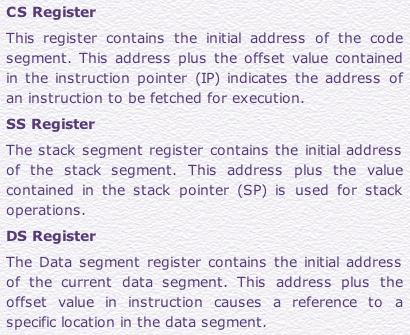
23 Segment registers In 8086/88 the processors have 4 segments registers Code Segment register (CS), Data Segment register (DS), Extra Segment register (ES) and Stack Segment (SS) register. All are 16 bit registers. Each of the Segment registers store the upper 16 bit address of the starting address of the corresponding segments
24 24 24
25 MEMORY BIU Segment Registers CSR 34BA DSR 44EB ESR 54EB 695E SSR 34BA0 44B9F 44EB0 54EAF 54EB0 64EAF 695E0 795DF CODE (64k) DATA (64K) EXTRA (64K) STACK (64K) 1 MB Each segment register store the upper 16 bit of the starting address of the segments 25 25
26 26 26
27 Segment and Address register combination CS:IP SS:SP SS:BP DS:BX DS:SI DS:DI (for other than string operations) ES:DI (for string operations) 27 27
28 Block diagram of 8086 RCET Microprocessor & Microcontroller 28 28
29 Block diagram of 8086 RCET Microprocessor & Microcontroller 29 29
30 General Purpose Registers AX - the Accumulator BX -the Base Register CX -the Count Register DX -the Data Register Normally used for storing temporary results Each of the registers is 16 bits wide (AX, BX, CX, DX) Can be accessed as either 16 or 8 bits AX, AH, AL 30 30
31 General Purpose Registers AX Accumulator Register Preferred register to use in arithmetic, logic and data transfer instructions because it generates the shortest Machine Language Code Must be used in multiplication and division operations Must also be used in I/O operations BX Base Register Also serves as an address register 31 31
32 General Purpose Registers CX Count register Used as a loop counter Used in shift and rotate operations DX Data register Used in multiplication and division Also used in I/O operations 32 32
33 Pointer and Index Registers All 16 bits wide, L/H bytes are not accessible Used as memory pointers Example: MOV AH, [SI] Move the byte stored in memory location whose address is contained in register SI to register AH IP is not under direct control of the programmer 33 33
34 Flag Register Overflow Direction Parity Carry Interrupt enable Trap Sign Zero Auxiliary Carry 6 are status flags 3 are control flag 34 34
35 8086 Programmer s Model BIU registers (20 bit adder) ES CS SS DS IP Extra Segment Code Segment Stack Segment Data Segment Instruction Pointer EU registers AX BX CX DX AH BH CH DH SP BP SI DI FLAGS AL BL CL DL Accumulator Base Register Count Register Data Register Stack Pointer Base Pointer Source Index Register Destination Index Register 35 35
36 The Stack The stack is used for temporary storage of information such as data or addresses. When a CALL is executed, the 8086 automatically PUSHes thecurrentvalueofcsandipontothe stack. Other registers can also be pushed Before return from the subroutine, POP instructions can be used to pop values back from the stack into the corresponding registers

37 The Stack 37 37
38 Hardware Architecture of INTEL
39 Hardware Architecture of INTEL 8086 Pin Diagram and Pin Details min/max mode Hardware organization of address space Control signals Coprocessor and Multiprocessor configuration I/O interfaces 39 39
40 INTEL Pin Diagram Microprocessor & Microcontroller 40 40
41 INTEL Pin Details Ground Clock Duty cycle: 33% Power Supply 5V ±10% Reset Registers, seg regs, flags CS: FFFFH, IP: 0000H If high for minimum 4 clks Microprocessor & Microcontroller 41 41
42 INTEL Pin Details Address/Data Bus: Contains address bits A 15 -A 0 when ALE is 1 & data bits D 15 D 0 when ALE is 0. Address Latch Enable: When high, multiplexed address/data bus contains address information. Microprocessor & Microcontroller 42 42
43 INTEL Pin Details INTERRUPT Non -maskable interrupt Interrupt acknowledge Interrupt request Microprocessor & Microcontroller 43 43
44 INTEL Pin Details Direct Memory Access Hold Hold acknowledge Microprocessor & Microcontroller 44 44

45 INTEL Pin Details Address/Status Bus Address bits A 19 A 16 & Status bits S 6 S 3 Microprocessor & Microcontroller 45 45
46 INTEL Pin Details BHE#, A 0 : 0,0: Whole word (16-bits) 0,1: High byte to/from odd address 1,0: Low byte to/from even address Bus High Enable/S7 Enables most significant data bits D 15 D 8 during read or write operation. S 7 : Always 1. 1,1: No selection Microprocessor & Microcontroller 46 46
47 INTEL Pin Details Min/Max mode Minimum Mode: +5V Maximum Mode: 0V Minimum Mode Pins Maximum Mode Pins Microprocessor & Microcontroller 47 47
48 Minimum Mode- Pin Details Read Signal Write Signal Memory or I/0 Data Transmit/Receive Microprocessor & Microcontroller Data Bus Enable 48 48
49 Maximum Mode - Pin Details S2 S1 S0 000: INTA 001: read I/O port 010: write I/O port 011: halt 100: code access 101: read memory 110: write memory 111: none -passive Status Signal Inputs to 8288 to generate eliminated signals due to max mode. Microprocessor & Microcontroller 49 49
50 Maximum Mode - Pin Details Lock Output Used to lock peripherals off the system Activated by using the LOCK: prefix on any instruction DMA Request/Grant Lock Output Microprocessor & Microcontroller 50 50
51 Maximum Mode - Pin Details QS1 QS0 00: Queue is idle 01: First byte of opcode 10: Queue is empty 11: Subsequent byte of opcode Queue Status Used by numeric coprocessor (8087) Microprocessor & Microcontroller 51 51
52 Minimum Mode 8086 System Microprocessor & Microcontroller 52 52
53 Maximum Mode 8086 System Microprocessor & Microcontroller 53 53
54 Flow Control Instructions - Cont. Single-flag jumps JS jump if sign negative JNS jump if nonnegative sign JP/JPE jump if parity even JNP/JPO jump if parity odd Jump based on CX JCXZ Loop Instructions Loop Loopnz/Loopne Loopz/Loope All jump instructions have no effect on the flags. 54
55 Branching Structures: IF-Then Example: If AX < 0 Then Replace AX by AX ENDIF ; if AX < 0 ;then END_IF: CMP AX, 0 JNL END_IF NEG AX 55
56 Example: If AL <= BL Then Display character in AL Else Display character in BL ENDIF IF-Then-Else ; if AL<=BL ;then ELSE_: DISPLAY: END_IF: MOV AH, 2 CMP AL, BL JNBE ELSE_ MOV DL, AL JMP DISPLAY MOV DL, BL INT 21H 56
57 CASE Example: CASE AX <0: put 1 in BX =0: put 0 in BX >0: put 1 in BX END_CASE ; case AX CMP AX, 0 JL NEGATIVE JE ZERO JG POSITIVE NEGATIVE: MOV BX, -1 JMP END_CASE ZERO: MOV BX, 0 JMP END_CASE POSITIVE: MOV BX, 1 END_CASE: 57
58 CASE Cont. Example: CASE AL 1,3: display o 2,4: display e END_CASE ; case AL CMP AL, 1 ; 1, 3: JE ODD CMP AL, 3 JE ODD CMP AL, 2 ; 2, 4: JE EVEN CMP AL, 4 JE EVEN JMP END_CASE ODD: MOV DL, o JMP DISPLAY EVEN: MOV DL, e DISPLAY: MOV AH, 2 INT 21H END_CASE: 58
59 Loop Next Dec Cx If CX<>0 JMP Next Loopz/loope Next Loop Instructions Dec Cx If (CX<>0) AND (ZF=1) JMP Next Loopnz/loopne Next Dec Cx If (CX<>0) AND (ZF=0) JMP Next 59
60 FOR LOOP Example: For 80 times DO Display * END_IF Next: MOV CX, 80 MOV AH, 2 MOV DL, * INT 21H Loop Next 60
Intel 8086 MICROPROCESSOR. By Y V S Murthy
 Intel 8086 MICROPROCESSOR By Y V S Murthy 1 Features It is a 16-bit μp. 8086 has a 20 bit address bus can access up to 2 20 memory locations (1 MB). It can support up to 64K I/O ports. It provides 14,
Intel 8086 MICROPROCESSOR ARCHITECTURE
 Intel 8086 MICROPROCESSOR ARCHITECTURE 1 Features It is a 16-bit μp. 8086 has a 20 bit address bus can access up to 2 20 memory locations (1 MB). It can support up to 64K I/O ports. It provides 14, 16
A Presentation created By Ramesh.K Press Ctrl+l for full screen view
 Press Ctrl+l for full screen view A Presentation created By Ramesh.K rameshpkd@gmail.com Press Ctrl+l for full screen view A Microprocessor sor is a multipurpose, programmable logic device that reads binary
Internal architecture of 8086
 Case Study: Intel Processors Internal architecture of 8086 Slide 1 Case Study: Intel Processors FEATURES OF 8086 It is a 16-bit μp. 8086 has a 20 bit address bus can access up to 220 memory locations (1
8086 INTERNAL ARCHITECTURE
 8086 INTERNAL ARCHITECTURE Segment 2 Intel 8086 Microprocessor The 8086 CPU is divided into two independent functional parts: a) The Bus interface unit (BIU) b) Execution Unit (EU) Dividing the work between
MICROPROCESSOR PROGRAMMING AND SYSTEM DESIGN
 MICROPROCESSOR PROGRAMMING AND SYSTEM DESIGN ROAD MAP SDK-86 Intel 8086 Features 8086 Block Diagram 8086 Architecture Bus Interface Unit Execution Unit 8086 Architecture 8086 Programmer s Model Flag Register
icroprocessor istory of Microprocessor ntel 8086:
 Microprocessor A microprocessor is an electronic device which computes on the given input similar to CPU of a computer. It is made by fabricating millions (or billions) of transistors on a single chip.
Code segment Stack segment
 Registers Most of the registers contain data/instruction offsets within 64 KB memory segment. There are four different 64 KB segments for instructions, stack, data and extra data. To specify where in 1
Introduction to Microprocessor
 Introduction to Microprocessor The microprocessor is a general purpose programmable logic device. It is the brain of the computer and it performs all the computational tasks, calculations data processing
SPRING TERM BM 310E MICROPROCESSORS LABORATORY PRELIMINARY STUDY
 BACKGROUND 8086 CPU has 8 general purpose registers listed below: AX - the accumulator register (divided into AH / AL): 1. Generates shortest machine code 2. Arithmetic, logic and data transfer 3. One
Lecture 5:8086 Outline: 1. introduction 2. execution unit 3. bus interface unit
 Lecture 5:8086 Outline: 1. introduction 2. execution unit 3. bus interface unit 1 1. introduction The internal function of 8086 processor are partitioned logically into processing units,bus Interface Unit(BIU)
UNIT II OVERVIEW MICROPROCESSORS AND MICROCONTROLLERS MATERIAL. Introduction to 8086 microprocessors. Architecture of 8086 processors
 OVERVIEW UNIT II Introduction to 8086 microprocessors Architecture of 8086 processors Register Organization of 8086 Memory Segmentation of 8086 Pin Diagram of 8086 Timing Diagrams for 8086 Interrupts of
ADVANCE MICROPROCESSOR & INTERFACING
 VENUS INTERNATIONAL COLLEGE OF TECHNOLOGY Gandhinagar Department of Computer Enggineering ADVANCE MICROPROCESSOR & INTERFACING Name : Enroll no. : Class Year : 2014-15 : 5 th SEM C.E. VENUS INTERNATIONAL
CC411: Introduction To Microprocessors
 CC411: Introduction To Microprocessors OBJECTIVES this chapter enables the student to: Describe the Intel family of microprocessors from 8085 to Pentium. In terms of bus size, physical memory & special
Program controlled semiconductor device (IC) which fetches (from memory), decodes and executes instructions.
 which fetches (from memory), decodes and executes instructions.") 8086 Microprocessor Microprocessor Program controlled semiconductor device (IC) which fetches (from memory), decodes and executes instructions. It is used as CPU (Central Processing Unit) in computers.
8086 Microprocessor Microprocessor Program controlled semiconductor device (IC) which fetches (from memory), decodes and executes instructions. It is used as CPU (Central Processing Unit) in computers.
Lecture 5: Computer Organization Instruction Execution. Computer Organization Block Diagram. Components. General Purpose Registers.
 Lecture 5: Computer Organization Instruction Execution Computer Organization Addressing Buses Fetch-Execute Cycle Computer Organization CPU Control Unit U Input Output Memory Components Control Unit fetches
UNIT 1. Introduction to microprocessor. Block diagram of simple computer or microcomputer.
 UNIT 1 Unit 1 contents at a glance: 1. Architecture of 8086 microprocessor, 2. Register organization, 3. 8086 flag register and its functions, 4. addressing modes of 8086, 5. Pin diagram of 8086, 6. Minimum
SRI VENKATESWARA COLLEGE OF ENGINEERING AND TECHNOLOGY DEPARTMENT OF ECE EC6504 MICROPROCESSOR AND MICROCONTROLLER (REGULATION 2013)
") SRI VENKATESWARA COLLEGE OF ENGINEERING AND TECHNOLOGY DEPARTMENT OF ECE EC6504 MICROPROCESSOR AND MICROCONTROLLER (REGULATION 2013) UNIT I THE 8086 MICROPROCESSOR PART A (2 MARKS) 1. What are the functional
SRI VENKATESWARA COLLEGE OF ENGINEERING AND TECHNOLOGY DEPARTMENT OF ECE EC6504 MICROPROCESSOR AND MICROCONTROLLER (REGULATION 2013) UNIT I THE 8086 MICROPROCESSOR PART A (2 MARKS) 1. What are the functional
UNIT-I. 1.Draw and explain the Architecture of a 8085 Microprocessor?
 UNIT-I INTRODUCTION TO MICROPROCESSOR A common way of categorizing microprocessors is by the no. of bits that their ALU can work with at a time. (i) The first commercially available microprocessor was
UNIT 2 PROCESSORS ORGANIZATION CONT.
 UNIT 2 PROCESSORS ORGANIZATION CONT. Types of Operand Addresses Numbers Integer/floating point Characters ASCII etc. Logical Data Bits or flags x86 Data Types Operands in 8 bit -Byte 16 bit- word 32 bit-
EC-333 Microprocessor and Interfacing Techniques
 EC-333 Microprocessor and Interfacing Techniques Lecture 3 The Microprocessor and its Architecture Dr Hashim Ali Fall - 2018 Department of Computer Science and Engineering HITEC University Taxila Slides
ELE 3230 Microprocessors and Computer Systems
 ELE 3230 Microprocessors and Computer Systems Chapter 4 8088 System Architecture (*Hall:ch2; Brey:ch1; Triebel:ch2) ELE 3230 - Chapter 4 1 Historical Background 1969/70 Intel 4004, first Microprocessor
EXPERIMENT WRITE UP. LEARNING OBJECTIVES: 1. Get hands on experience with Assembly Language Programming 2. Write and debug programs in TASM/MASM
 EXPERIMENT WRITE UP AIM: Assembly language program for 16 bit BCD addition LEARNING OBJECTIVES: 1. Get hands on experience with Assembly Language Programming 2. Write and debug programs in TASM/MASM TOOLS/SOFTWARE
Microprocessor. By Mrs. R.P.Chaudhari Mrs.P.S.Patil
 Microprocessor By Mrs. R.P.Chaudhari Mrs.P.S.Patil Chapter 1 Basics of Microprocessor CO-Draw Architecture Of 8085 Salient Features of 8085 It is a 8 bit microprocessor. It is manufactured with N-MOS technology.
UNIT-1. It is a 16-bit Microprocessor (μp).it s ALU, internal registers works with 16bit binary word.
.it s ALU, internal registers works with 16bit binary word.") UNIT-1 Introduction to 8086: 8086 Microprocessor is an enhanced version of 8085Microprocessor that was designed by Intel in 1976. It is a 16-bit Microprocessor having 20 address lines and16 data lines
UNIT-1 Introduction to 8086: 8086 Microprocessor is an enhanced version of 8085Microprocessor that was designed by Intel in 1976. It is a 16-bit Microprocessor having 20 address lines and16 data lines
INTRODUCTION TO MICROPROCESSORS
 INTRODUCTION TO MICROPROCESSORS Richa Upadhyay Prabhu NMIMS s MPSTME richa.upadhyay@nmims.edu January 7, 2016 Richa Upadhyay Prabhu (MPSTME) INTRODUCTION January 7, 2016 1 / 63 Course Design Prerequisite:
Unit I Introduction. Department of Electronics and Communication Engineering VARDHAMAN COLLEGE OF ENGINEERING Shamshabad, Hyderabad , India.
 Unit I Introduction Department of Electronics and Communication Engineering VARDHAMAN COLLEGE OF ENGINEERING Shamshabad, Hyderabad 501218, India. Pre-requisites Digital Logic Design (A1404) Computer Architecture
Basic characteristics & features of 8086 Microprocessor Dr. M. Hebaishy
 Basic characteristics & features of 8086 Microprocessor Dr. M. Hebaishy Digital Logic Design Ch1-1 8086 Microprocessor Features: The 8086 microprocessor is a 16 bit microprocessor. The term 16 bit means
Topic 2 :16 Bit Microprocessor: 8086 (24 Marks)
") Topic 2 :16 Bit Microprocessor: 8086 (24 Marks) Features of 8086 8086 is a 16 bit processor. It s ALU, internal registers works with 16bit binary word 8086 has a 16bit data bus. It can read or write data
Topic 2 :16 Bit Microprocessor: 8086 (24 Marks) Features of 8086 8086 is a 16 bit processor. It s ALU, internal registers works with 16bit binary word 8086 has a 16bit data bus. It can read or write data
VARDHAMAN COLLEGE OF ENGINEERING (AUTONOMOUS) Shamshabad, Hyderabad
 Shamshabad, Hyderabad") Introduction to MS-DOS Debugger DEBUG In this laboratory, we will use DEBUG program and learn how to: 1. Examine and modify the contents of the 8086 s internal registers, and dedicated parts of the memory
Introduction to MS-DOS Debugger DEBUG In this laboratory, we will use DEBUG program and learn how to: 1. Examine and modify the contents of the 8086 s internal registers, and dedicated parts of the memory
 Question Bank Part-A UNIT I- THE 8086 MICROPROCESSOR 1. What is microprocessor? A microprocessor is a multipurpose, programmable, clock-driven, register-based electronic device that reads binary information
CHETTINAD COLLEGE OF ENGINEERING AND TECHNOLOGY COMMUNICATION ENGINEERING REG 2008 TWO MARKS QUESTION AND ANSWERS
 CHETTINAD COLLEGE OF ENGINEERING AND TECHNOLOGY B.E.,/B.TECH., ELECTRONICS EC6504 MICROPROCESSORS & MICRO CONTROLLERS COMMUNICATION ENGINEERING REG 2008 TWO MARKS QUESTION AND ANSWERS UNIT 1 AND 2 CS SUBJECT
The 8086 Microprocessor
 The 8086 Microprocessor 1. Draw the pin diagram of 8086. Ans. There would be two pin diagrams one for MIN mode and the other for MAX mode of 8086, shown in Figs. 11.1 and 11.2 respectively. The pins that
Assembly Language. Dr. Esam Al_Qaralleh CE Department Princess Sumaya University for Technology. Overview of Assembly Language
 4345 Assembly Language Assembly Language Dr. Esam Al_Qaralleh CE Department Princess Sumaya University for Technology Assembly Language 3-1 Overview of Assembly Language Advantages: Faster as compared
16-Bit Intel Processor Architecture
 IBM-PC Organization 16-Bit Intel Processor Architecture A-16 bit microprocessor can operate on 16 bits of data at a time. 8086/8088 have the simplest structure 8086/8088 have the same instruction set,
EEM336 Microprocessors I. The Microprocessor and Its Architecture
 EEM336 Microprocessors I The Microprocessor and Its Architecture Introduction This chapter presents the microprocessor as a programmable device by first looking at its internal programming model and then
Intel 8086: Instruction Set
 IUST-EE (Chapter 6) Intel 8086: Instruction Set 1 Outline Instruction Set Data Transfer Instructions Arithmetic Instructions Bit Manipulation Instructions String Instructions Unconditional Transfer Instruction
 UNIT II SYSTEM BUS STRUCTURE 1. Differentiate between minimum and maximum mode 2. Give any four pin definitions for the minimum mode. 3. What are the pins that are used to indicate the type of transfer
CS401 Assembly Language Solved MCQS From Midterm Papers
 CS401 Assembly Language Solved MCQS From Midterm Papers May 14,2011 MC100401285 Moaaz.pk@gmail.com MC100401285@gmail.com PSMD01(IEMS) Question No:1 ( Marks: 1 ) - Please choose one The first instruction
SYSC3601 Microprocessor Systems. Unit 2: The Intel 8086 Architecture and Programming Model
 SYSC3601 Microprocessor Systems Unit 2: The Intel 8086 Architecture and Programming Model Topics/Reading SYSC3601 2 Microprocessor Systems 1. Registers and internal architecture (Ch 2) 2. Address generation
Northern India Engineering College, Delhi (GGSIP University) PAPER I
 PAPER I") PAPER I Q1.Explain IVT? ANS. interrupt vector table is a memory space for storing starting addresses of all the interrupt service routine. It stores CS:IP PAIR corresponding to each ISR. An interrupt vector
PAPER I Q1.Explain IVT? ANS. interrupt vector table is a memory space for storing starting addresses of all the interrupt service routine. It stores CS:IP PAIR corresponding to each ISR. An interrupt vector
Ex: Write a piece of code that transfers a block of 256 bytes stored at locations starting at 34000H to locations starting at 36000H. Ans.
 INSTRUCTOR: ABDULMUTTALIB A H ALDOURI Conditional Jump Cond Unsigned Signed = JE : Jump Equal JE : Jump Equal ZF = 1 JZ : Jump Zero JZ : Jump Zero ZF = 1 JNZ : Jump Not Zero JNZ : Jump Not Zero ZF = 0
PESIT Bangalore South Campus
 INTERNAL ASSESSMENT TEST 2 Date : 02/04/2018 Max Marks: 40 Subject & Code : Microprocessor (15CS44) Section : IV A and B Name of faculty: Deepti.C Time : 8:30 am-10:00 am Note: Note: Answer any five complete
Marking Scheme. Examination Paper Department of CE. Module: Microprocessors (630313)
") Philadelphia University Faculty of Engineering Marking Scheme Examination Paper Department of CE Module: Microprocessors (630313) Final Exam Second Semester Date: 02/06/2018 Section 1 Weighting 40% of
Philadelphia University Faculty of Engineering Marking Scheme Examination Paper Department of CE Module: Microprocessors (630313) Final Exam Second Semester Date: 02/06/2018 Section 1 Weighting 40% of
Arithmetic Instructions
 Segment 3C Arithmetic Instructions This topic covers the following instructions: Addition (ADD, INC, ADC) Subtraction (SUB, DEC, SBB,CMP) Multiplication (MUL, IMUL) Division (DIV, IDIV) BCD Arithmetic
The higher the values of above, the more powerful the CPU. Microprocessors are categorized in additional as: RISC or CISC.
 MICROPROCESSOR: A silicon chip that contains a CPU. A microprocessor (sometimes abbreviated μp) is a digital electronic component with miniaturized transistors on a single semiconductor integrated circuit
WINTER 12 EXAMINATION Subject Code : Model Answer Page No : / N. a) Describe the function of SID and SOD pins of 8085 microprocessor
 Describe the function of SID and SOD pins of 8085 microprocessor") Subject Code : Model Answer Page No : / N Q.1) SOLVE ANY FIVE : (20 MARKS) a) Describe the function of SID and SOD pins of 8085 microprocessor Ans: - SID: - (2 Mark) Serial Input Data SID pin is used to
Subject Code : Model Answer Page No : / N Q.1) SOLVE ANY FIVE : (20 MARKS) a) Describe the function of SID and SOD pins of 8085 microprocessor Ans: - SID: - (2 Mark) Serial Input Data SID pin is used to
EC 333 Microprocessor and Interfacing Techniques (3+1)
") EC 333 Microprocessor and Interfacing Techniques (3+1) Lecture 6 8086/88 Microprocessor Programming (Arithmetic Instructions) Dr Hashim Ali Fall 2018 Department of Computer Science and Engineering HITEC
EC 333 Microprocessor and Interfacing Techniques (3+1) Lecture 6 8086/88 Microprocessor Programming (Arithmetic Instructions) Dr Hashim Ali Fall 2018 Department of Computer Science and Engineering HITEC
Lecture (02) The Microprocessor and Its Architecture By: Dr. Ahmed ElShafee
 The Microprocessor and Its Architecture By: Dr. Ahmed ElShafee") Lecture (02) The Microprocessor and Its Architecture By: Dr. Ahmed ElShafee ١ INTERNAL MICROPROCESSOR ARCHITECTURE Before a program is written or instruction investigated, internal configuration of the
Lecture (02) The Microprocessor and Its Architecture By: Dr. Ahmed ElShafee ١ INTERNAL MICROPROCESSOR ARCHITECTURE Before a program is written or instruction investigated, internal configuration of the
Architecture of 8086 Microprocessor
 MCQ on Microprocessor and Interfacing Technique S.E.Compure (Sem-II) UNIT 1 Architecture of 8086 Microprocessor 1 marks Questions 1. Which is first microprocessor? (a) 8008 (b) 8085 (c) 8086 (d) 4004 2.
8086 Hardware Specification
 Content: Segment 5 8086 Hardware Specification 8086 Modes of operation. Pin diagram and pin function of 8086. 8284A Clock generator operation and pin functions. Prepared By: Mohammed Abdul Kader Lecturer,
Basic Execution Environment
 Basic Execution Environment 3 CHAPTER 3 BASIC EXECUTION ENVIRONMENT This chapter describes the basic execution environment of an Intel Architecture processor as seen by assembly-language programmers.
Module 3 Instruction Set Architecture (ISA)
") Module 3 Instruction Set Architecture (ISA) I S A L E V E L E L E M E N T S O F I N S T R U C T I O N S I N S T R U C T I O N S T Y P E S N U M B E R O F A D D R E S S E S R E G I S T E R S T Y P E S O
Module 3 Instruction Set Architecture (ISA) I S A L E V E L E L E M E N T S O F I N S T R U C T I O N S I N S T R U C T I O N S T Y P E S N U M B E R O F A D D R E S S E S R E G I S T E R S T Y P E S O
Chapter 2 COMPUTER SYSTEM HARDWARE
 Chapter 2 COMPUTER SYSTEM HARDWARE A digital computer system consists of hardware and software. The hardware consists of the physical components of the system, whereas the software is the collection of
Chapter Four Instructions Set
 Chapter Four Instructions set Instructions set 8086 has 117 instructions, these instructions divided into 6 groups: 1. Data transfer instructions 2. Arithmetic instructions 3. Logic instructions 4. Shift
US06CCSC04: Introduction to Microprocessors and Assembly Language UNIT 1: Assembly Language Terms & Directives
 Introduction: US06CCSC04: Introduction to Microprocessors and A microprocessor is the chip containing some control and logic circuits that is capable of a making arithmetic and logical decision based on
The x86 Microprocessors. Introduction. The 80x86 Microprocessors. 1.1 Assembly Language
 The x86 Microprocessors Introduction 1.1 Assembly Language Numbering and Coding Systems Human beings use the decimal system (base 10) Decimal digits: 0, 1, 2, 3, 4, 5, 6, 7, 8, 9 Computer systems use the
EXPERIMENT WRITE UP. LEARNING OBJECTIVES: 1. Get hands on experience with Assembly Language Programming 2. Write and debug programs in TASM/MASM
 EXPERIMENT WRITE UP AIM: Assembly language program to search a number in given array. LEARNING OBJECTIVES: 1. Get hands on experience with Assembly Language Programming 2. Write and debug programs in TASM/MASM
8086 Microprocessors & Peripherals
 8086 Microprocessors & Peripherals (06IT/BM - 52) Sessions handled by Prof. M.V. SREENIVAS RAO. GSSSIETW, MYSORE Prof. M. SHIVAKUMAR. BIET, DAVANGERE Prof. VAGEESH.V.KANTLI. BIET, DAVANGERE 1 8086 MICROPROCESSOR
Marking Scheme. Examination Paper. Module: Microprocessors (630313)
") Philadelphia University Faculty of Engineering Marking Scheme Examination Paper Department of CE Module: Microprocessors (630313) Final Exam Second Semester Date: 12/06/2017 Section 1 Weighting 40% of
Philadelphia University Faculty of Engineering Marking Scheme Examination Paper Department of CE Module: Microprocessors (630313) Final Exam Second Semester Date: 12/06/2017 Section 1 Weighting 40% of
Hardware and Software Architecture. Chapter 2
 Hardware and Software Architecture Chapter 2 1 Basic Components The x86 processor communicates with main memory and I/O devices via buses Data bus for transferring data Address bus for the address of a
Introduction to IA-32. Jo, Heeseung
 Introduction to IA-32 Jo, Heeseung IA-32 Processors Evolutionary design Starting in 1978 with 8086 Added more features as time goes on Still support old features, although obsolete Totally dominate computer
Microprocessor and Assembly Language Week-5. System Programming, BCS 6th, IBMS (2017)
") Microprocessor and Assembly Language Week-5 System Programming, BCS 6th, IBMS (2017) High Speed Memory Registers CPU store data temporarily in these location CPU process, store and transfer data from one
Microprocessor and Assembly Language Week-5 System Programming, BCS 6th, IBMS (2017) High Speed Memory Registers CPU store data temporarily in these location CPU process, store and transfer data from one
INTRODUCTION TO IA-32. Jo, Heeseung
 INTRODUCTION TO IA-32 Jo, Heeseung IA-32 PROCESSORS Evolutionary design Starting in 1978 with 8086 Added more features as time goes on Still support old features, although obsolete Totally dominate computer
Section 001. Read this before starting!
 Points missed: Student's Name: Total score: /100 points East Tennessee State University Department of Computer and Information Sciences CSCI 2150 (Tarnoff) Computer Organization TEST 3 for Fall Semester,
if 2 16bit operands multiplied the result will be
 how many operands in ADC? ans:3 how 32 bit word is defined? ans define double if 2 16bit operands multiplied the result will be ans 32bit if div by ero occurs then?? ans div by zero int for software int
8/26/2010. Introduction to 8085 BLOCK DIAGRAM OF INTEL Introduction to Introduction to Three Units of 8085
 BLOCK DIAGRAM OF INTEL 8085 GURSHARAN SINGH TATLA Introduction to 8085 It was introduced in 1977. It is 8-bit microprocessor. Its actual name is 8085 A. It is single NMOS device. It contains 6200 transistors
The Microprocessor and its Architecture
 The Microprocessor and its Architecture Contents Internal architecture of the Microprocessor: The programmer s model, i.e. The registers model The processor model (organization) Real mode memory addressing
Microcomputer Architecture..Second Year (Sem.2).Lecture(2) مدرس المادة : م. سندس العزاوي... قسم / الحاسبات
.Lecture(2) مدرس المادة : م. سندس العزاوي... قسم / الحاسبات") 1) Input/output In computing, input/output or I/O, is the communication between an information processing system (such as a computer) and the outside world, possibly a human or another information processing
1) Input/output In computing, input/output or I/O, is the communication between an information processing system (such as a computer) and the outside world, possibly a human or another information processing
12-Dec-11. Gursharan Singh Maninder Kaur. Introduction to 8085 BLOCK DIAGRAM OF INTEL Introduction to Introduction to 8085
 mailme@gursharansingh.in BLOCK DIAGRAM OF INTEL 8085 mailme@maninderkaur.in Introduction to 8085 It was introduced in 1977. It is 8-bit microprocessor. Its actual name is 8085 A. It is single NMOS device.
Vidyalankar. Vidyalankar T.E. Sem. V [CMPN] Microprocessors Prelim Question Paper Solution. 1. (a)
![Vidyalankar. Vidyalankar T.E. Sem. V [CMPN] Microprocessors Prelim Question Paper Solution. 1. (a)](/thumbs/85/91719469.jpg "Vidyalankar. Vidyalankar T.E. Sem. V [CMPN] Microprocessors Prelim Question Paper Solution. 1. (a)") 1. (a) Step 1 : Total EPROM required Chip size available No.of chips required = 2 T.E. Sem. V [CMPN] Microprocessors Prelim Question Paper Solution = 64 KB = 32 KB No.of sets required = 2 1 2 Set 1 = Ending
1. (a) Step 1 : Total EPROM required Chip size available No.of chips required = 2 T.E. Sem. V [CMPN] Microprocessors Prelim Question Paper Solution = 64 KB = 32 KB No.of sets required = 2 1 2 Set 1 = Ending
INDEX. 1 Study of intel 8085 micropeocessor kit. 2 Program to find addition of two 8 bit no. 3 Program to find subtraction of two 8 bit no.
 INDEX PROGRAM NO. NAME OF THE PROGRAM 1 Study of intel 8085 micropeocessor kit SIGNATURE 2 Program to find addition of two 8 bit no. 3 Program to find subtraction of two 8 bit no. 4 Program to find 1 s
The functional block diagram of 8085A is shown in fig.4.1.
 Lecture-13 Internal Architecture of Intel 05A The functional block diagram of 05A is shown in fig.4.1. INTA INTR RST7.5 RST5.5 RST6.5 TRAP SOD SID INTERRUPT SERIAL I/O (Internal Bus) FR(S) IR() B() C()
Microcomputer Architecture and Programming
 IUST-EE (Chapter 1) Microcomputer Architecture and Programming 1 Outline Basic Blocks of Microcomputer Typical Microcomputer Architecture The Single-Chip Microprocessor Microprocessor vs. Microcontroller
LECTURE NOTES MICROPROCESSORS AND INTERFACING DEVICES
 LECTURE NOTES ON MICROPROCESSORS AND INTERFACING DEVICES III B. Tech II semester (JNTUH-R15) Mr.R Mahendhar Reddy, Associate Professor, ECE ELECTRICAL AND ELECTRONICS ENGINEERING INSTITUTE OF AERONAUTICAL
Chapter 1: Basics of Microprocessor [08 M]
![Chapter 1: Basics of Microprocessor [08 M]](/thumbs/77/75860546.jpg "Chapter 1: Basics of Microprocessor [08 M]") Microprocessor: Chapter 1: Basics of Microprocessor [08 M] It is a semiconductor device consisting of electronic logic circuits manufactured by using either a Large scale (LSI) or Very Large Scale (VLSI)
Microprocessor: Chapter 1: Basics of Microprocessor [08 M] It is a semiconductor device consisting of electronic logic circuits manufactured by using either a Large scale (LSI) or Very Large Scale (VLSI)
2. List the five interrupt pins available in INTR, TRAP, RST 7.5, RST 6.5, RST 5.5.
 DHANALAKSHMI COLLEGE OF ENGINEERING DEPARTMENT OF ELECTRICAL AND ELECTRONICS ENGINEERING EE6502- MICROPROCESSORS AND MICROCONTROLLERS UNIT I: 8085 PROCESSOR PART A 1. What is the need for ALE signal in
Addressing Modes on the x86
 Addressing Modes on the x86 register addressing mode mov ax, ax, mov ax, bx mov ax, cx mov ax, dx constant addressing mode mov ax, 25 mov bx, 195 mov cx, 2056 mov dx, 1000 accessing data in memory There
CSC 2400: Computer Systems. Towards the Hardware: Machine-Level Representation of Programs
 CSC 2400: Computer Systems Towards the Hardware: Machine-Level Representation of Programs Towards the Hardware High-level language (Java) High-level language (C) assembly language machine language (IA-32)
Summer 2003 Lecture 4 06/14/03
 Summer 2003 Lecture 4 06/14/03 LDS/LES/LSS General forms: lds reg,mem lseg reg,mem Load far pointer ~~ outside of current segment {E.g., load reg w/value @ mem, & seg w/mem+2 XCHG Exchange values General
Signed number Arithmetic. Negative number is represented as
 Signed number Arithmetic Signed and Unsigned Numbers An 8 bit number system can be used to create 256 combinations (from 0 to 255), and the first 128 combinations (0 to 127) represent positive numbers
INSTRUCTOR: ABDULMUTTALIB A. H. ALDOURI
 Note: PUSHF / POPF have no operands The figure below shows that if (SS) = 3000H, (SP) = 0042H, so the execution of POP CX loads CX by the word 4050H form the stack segment. The SP is incremented by 2.
1-Operand instruction types 1 INC/ DEC/ NOT/NEG R/M. 2 PUSH/ POP R16/M16/SR/F 2 x ( ) = 74 opcodes 3 MUL/ IMUL/ DIV/ DIV R/M
 = 74 opcodes 3 MUL/ IMUL/ DIV/ DIV R/M") Increment R16 1-Operand instruction types 1 INC/ DEC/ NOT/NEG R/M 4 x (16+48) = 256 opcodes 2 PUSH/ POP R16/M16/SR/F 2 x (8+24+4+1) = 74 opcodes 3 MUL/ IMUL/ DIV/ DIV R/M 4 x (16+48) = 256 opcodes INC
Increment R16 1-Operand instruction types 1 INC/ DEC/ NOT/NEG R/M 4 x (16+48) = 256 opcodes 2 PUSH/ POP R16/M16/SR/F 2 x (8+24+4+1) = 74 opcodes 3 MUL/ IMUL/ DIV/ DIV R/M 4 x (16+48) = 256 opcodes INC
Mr. Sapan Naik 1. Babu Madhav Institute of Information Technology, UTU
 5 Years Integrated M.Sc.(IT) Semester 4 060010402 System Programming Question Bank Unit 1: Introduction 1. Write the decimal equivalent for each integral power of 2 from 2! to 2!". 2. Convert the following
Complex Instruction Set Computer (CISC)
") Introduction ti to IA-32 IA-32 Processors Evolutionary design Starting in 1978 with 886 Added more features as time goes on Still support old features, although obsolete Totally dominate computer market
Introduction ti to IA-32 IA-32 Processors Evolutionary design Starting in 1978 with 886 Added more features as time goes on Still support old features, although obsolete Totally dominate computer market
Instructions Involve a Segment Register (SR-field)
") BYTE 1 = 11000111 2 = C7 16 BYTE 2 = (MOD)000(R/M) = 100000112 = 83 16 BYTE 3 = 34 16 and BYTE 4 = 12 16 BYTE 5 = CD 16 and BYTE 6 = AB 16 The machine code for the instruction is: MOV [BP+DI+1234H], 0ABCDH
BYTE 1 = 11000111 2 = C7 16 BYTE 2 = (MOD)000(R/M) = 100000112 = 83 16 BYTE 3 = 34 16 and BYTE 4 = 12 16 BYTE 5 = CD 16 and BYTE 6 = AB 16 The machine code for the instruction is: MOV [BP+DI+1234H], 0ABCDH
CHAPTER 5 : Introduction to Intel 8085 Microprocessor Hardware BENG 2223 MICROPROCESSOR TECHNOLOGY
 CHAPTER 5 : Introduction to Intel 8085 Hardware BENG 2223 MICROPROCESSOR TECHNOLOGY The 8085A(commonly known as the 8085) : Was first introduced in March 1976 is an 8-bit microprocessor with 16-bit address
8086 INSTRUCTION SET
 8086 INSTRUCTION SET Complete 8086 instruction set Quick reference: AAA AAD AAM AAS ADC ADD AND CALL CBW CLC CLD CLI CMC CMP CMPSB CMPSW CWD DAA DAS DEC DIV HLT IDIV IMUL IN INC INT INTO I JA JAE JB JBE
PESIT Bangalore South Campus
 INTERNAL ASSESSMENT TEST 2 Date : 28/03/2016 Max Marks: 50 Subject & Code : Microprocessor (10CS45) Section: IV A and B Name of faculty: Deepti.C Time: 8:30-10:00 am Note: Answer any complete five questions
EC 333 Microprocessor and Interfacing Techniques (3+1)
") EC 333 Microprocessor and Interfacing Techniques (3+1) Lecture 7 8086/88 Microprocessor Programming (Data Movement Instructions) Dr Hashim Ali Spring 2018 Department of Computer Science and Engineering
EC 333 Microprocessor and Interfacing Techniques (3+1) Lecture 7 8086/88 Microprocessor Programming (Data Movement Instructions) Dr Hashim Ali Spring 2018 Department of Computer Science and Engineering
CG2007 Microprocessor systems.
 CG2007 Microprocessor systems Tutorial 1 Semester 2 AY 2011-12 Ganesh Iyer ganesh.vigneswara@gmail.com http://ganeshniyer.com About Me I have 3 years of Industry work experience in Bangalore, India. I
EEM336 Microprocessors I. Data Movement Instructions
 EEM336 Microprocessors I Data Movement Instructions Introduction This chapter concentrates on common data movement instructions. 2 Chapter Objectives Upon completion of this chapter, you will be able to:
1 MALP ( ) Unit-1. (1) Draw and explain the internal architecture of 8085.
 Unit-1. (1) Draw and explain the internal architecture of 8085.") (1) Draw and explain the internal architecture of 8085. The architecture of 8085 Microprocessor is shown in figure given below. The internal architecture of 8085 includes following section ALU-Arithmetic
(1) Draw and explain the internal architecture of 8085. The architecture of 8085 Microprocessor is shown in figure given below. The internal architecture of 8085 includes following section ALU-Arithmetic
Section 002. Read this before starting!
 Points missed: Student's Name: _ Total score: /100 points East Tennessee State University -- Department of Computer and Information Sciences CSCI 2150 Computer Organization Final Exam for Fall Semester,
SPRING TERM BM 310E MICROPROCESSORS LABORATORY PRELIMINARY STUDY
 BACKGROUND Segment The "SEGMENT" and "ENDS" directives indicate to the assembler the beginning and ending of a segment and have the following format label SEGMENT [options] ;place the statements belonging
US06CCSC04: Introduction to Microprocessors and Assembly Language UNIT 3: Assembly Language Instructions II
 Unconditional & Conditional JUMP instructions: Conditional JUMP instructions: JA/JNBE Jump if above / Jump if not Below or Equal These two mnemonics represent the same instruction. The term above and below
Week 2 The 80x86 Microprocessor Architecture
 Week 2 The 80x86 Microprocessor Architecture OBJECTIVES this chapter enables the student to: Describe the Intel family of microprocessors from 8085 to Pentium. In terms of bus size, physical memory & special
The 80386SX Processor Bus and Real-Mode Instruction Set
 EECE 379 : DESIGN OF DIGITAL AND MICROCOMPUTER SYSTEMS 2000/2001 WINTER SESSION, TERM 1 The 80386SX Processor Bus and Real-Mode Instruction Set This chapter describes the signals and operation of the Intel
CSC 8400: Computer Systems. Machine-Level Representation of Programs
 CSC 8400: Computer Systems Machine-Level Representation of Programs Towards the Hardware High-level language (Java) High-level language (C) assembly language machine language (IA-32) 1 Compilation Stages
MICROPROCESSOR QUESTION BANK. Unit 1
 QUESTION BANK Unit 1 1. Explain the term Microprocessor. ( CO1-K2) A microprocessor is a multipurpose, programmable logic device that receives binary instructions from a storage device called memory accepts