International Training Workshop on FPGA Design for Scientific Instrumentation and Computing November 2013
|
|
|
- Oliver Knight
- 6 years ago
- Views:
Transcription


1 International Training Workshop on FPGA Design for Scientific Instrumentation and Computing November 2013 Introduction to VHDL for Implementing Digital Designs into FPGAs Cristian SISTERNA National University of San Juan San Juan Argentina
2 Introduction to VHDL for Implementing Digital Designs into FPGAs 1
3 Introduction Hardware Very High Speed ICs V Language Description H D L 2


4 Hardware Description Language HDL (VHDL/Verilog) FPGA ASIC Xilinx Altera Lattice Actel 3
5 Hardware Description Language High level of abstraction Easy to debug if(reset= 1 ) then count <= 0; elsif(rising_edge(clk)) then count <= count+1; end if; Parameterized designs Re-uso IP Cores (free) available 4
6 What is not VHDL Verilog o VHDL IS NOT A programming language; IT IS A HARDWARE DESCRIPTION LENGUAGE Verilog o VHDL is not (yet) a highly abstract language: y(n) = 0.75y(n-1) + 0.3x(n) ; (Simulink/FPGA design flow) 5


7 HDL Synthesis Sub-Set Used to write code to simulate the behavior of a design VHDL VHDL Synthesizable Used to implement the design into hardware (for instance in FPGA) 6

8 VHDL - Synthesis VHDL Code with tmp select j <= w when 1000, x when 0100, y when 0010, z when 0001, '0 when others; Design Constraints NET CLOCK PERIOD = 50 ns; NET LOAD LOC = P Design Attributes attribute syn_encoding of my_fsm: type is one-hot ; Synthesis Tool FPGA list of Components and Connections FPGA Library of Components Virtex 4 Spartan 6 7
9 VHDL Description Examples x y sel 0 1 z if(sel= 1 ) then z <= y; else z <= x; end if; z <= y when sel= 1 else x; 8
10 VHDL Description Ejemplos d clk if(clk )then q <= d; end if; q if(clk )then q <= d; else q <= q; end if; if(rising_edge(clk))then q <= d; end if; 9
11 VHDL Module Structure ff.vhd d clk q entity I/O architecture Functionality 10
12 VHDL Estructura de un módulo ff.vhd entity ff is port( d,clk : in std_logic; q : out std_logic); end ff; d clk q architecture test of ff is begin process(clk) begin if(rising_edge(clk)) then q <= d; end if; end test; 11

13 VHDL Code Is it really Works?? Test Bench Stimulus Signals Unit Under Test Tested Signals 12
14 VHDL Simulation / Verification 13

15 VHDL-FPGA Flujo de Diseño Back-end Tools Synthesis & Optimization Place & Route Compilation Functional Verification Timing Verification Front-end Tools 14

16 Design Implemented in the FPGA 15

17 Software to Use: Xilinx ISE

18 FPGA Board to Use 17
19 VHDL Basic Language Elements 18
20 Identifiers A basic identifier: May only contain alphabetic letters (A to Z and a to z), decimal digits (0 to 9) and the underline character (_) Must start with an alphabetic letter May not end with an underline character May not include two successive underline characters VHDL is not case-sensitive No blank space(s) are allowed Examples: Same identifier Txclk, TxClk, TXCLK, TxCLK Legal identifiers Rst, Three_State_Enable, CS_244, Sel7D Illegal identifiers _Set, 80X86, large#bits, m RAM, add_ 19
21 Data Objects Each data object has a type and a class The type indicates what type of data can be hold by the data object The class indicates what can be done with the data object Classes Constant Variable Signal File std_logic std_ulogic integer Types boolean bit std_logic_vector unsigned... 20
22 Signal Class A Data Object of class signal can hold information not only about the value of the data, but also the time at which the signal takes the new value Different values can be assigned to a signal at different times using signal assignment statements A new value is not immediately assigned Signals are used to connect concurrent elements (like wires) 21
23 Signal Class Signals represent physical interconnect (wire) that communicate between processes as well as the I/O of the system Signals PROCESS Functional Block Signals PROCESS Functional Block Signals Signals 22
24 Signal Declaration in the Architecture Signal Declarations: A signal is declared in the declarative part of an architecture, and it has two parts: signal count_i: std_logic; Signal Keyword Signal Name (identifier) Signal Type boolean std_logic/std_ulogic std_(u)logic_vector unsigned signed integer 23
25 Signal Declarations Entity Port Declarations Port declarations appear in the port section of an entity declaration Each port declaration is separated by semicolon from the others A port declaration has three parts: [signal] reset_n: in std_logic; Signal Name Port Mode in out inout buffer Signal Type boolean std_logic/std_ulogic std_(u)logic_vector unsigned signed integer 24
26 Port Modes Mode in: cannot be assigned a value to, so it can only be read and it appears on the RHS of the signal assignment Mode out: can only be assigned to, so it can appear on the LHS of the signal assignment Mode inout: can be assigned to and be read, so in can appear on either side of an assignment. It is intended to be used only for bidirectional kind of I/O ports Mode buffer: can be assigned to and be read, so in can appear on either side of an assignment. However, do not use mode buffer! 25
27 Simple Signal Assignment count <= count + 1; carry_out <= (a and b) or (a and c) or (b and c); Z <= y; Left Hand Side (LHS) Target Signal Right Hand Side (RHS) Source Signal(s) LHS Signal Type RHS Signal Type 26
28 Signal Used as Interconnect LIBRARY IEEE; USE IEEE.STD_LOGIC_1164.ALL; ENTITY simp IS PORT ( r, t, g, h : IN STD_LOGIC; qb : OUT STD_LOGIC ); END ENTITY simp; r t g h qa qb ARCHITECTURE logic OF simp IS SIGNAL qa : STD_LOGIC; BEGIN qa <= r OR t; qb <= (qa AND NOT (g XOR h)); END ARCHITECTURE logic; Signal declaration inside architecture r, t, g, h, and qb are signals (by default) qa is a buried signal and needs to be declared 27
29 Signals Initial Values All signal have an initial value by the simulator when simulation begins (elaboration phase of the simulation): It can be assigned in the signal declaration signal ini_cnt: std_logic_vector(3 downto 0):= 1111 ; It will be given by default depending on the type of the signal: It will be the first value of the type: for type bit is 0 ; for type std_logic is U signal counter: std_logic_vector(7 downto 0); signal flag: boolean; constant bus_width: integer := 16; signal full_fifo: bit; signal addr: std_logic_vector(bus_width-1 downto 0); signal data: std_logic_vector(bus_width*2-1 downto 0); 28
30 Signals Initial Values For synthesis, there is no hardware interpretation of an intial value -> SYNHESIS IGNORES INTIAL VALUES Missmatch between SIMULATION & HARDWARE! Designer is responsable for setting the Hardware in a known intial state 29
31 Signal Declarations and Visibility package my_packg signal A; use my_packg.all; entity test port (B architecture example of test is signal C:... begin... my_process: process signal D: A B C D 30
32 Assigning Values to Signals signal temp : std_logic_vector (7 downto 0); Examples All bits temp <= ; temp <= x aa ; -- Hexadecimal VHDL also supports o for octal and b for binary Bit-slicing temp (7 DOWNTO 4) <= 1010 ; Single bit temp(7) <= 1 ; - Different values at different times rst <= x 00, x AA after 50 ns, x FF after 100 ns; -- just for simulation Use double-quotes ( ) to assign multi-bit values and singlequotes ( ) to assign single-bit values 31
33 Signals Resume Not immediately updated Declared within: Architecture Blocks Packages Implicit declaration in the entity declaration Visible for all the processes in the architecture In a combinatorial process synthesize as combinatorial logic In a sequential process synthesize as registers Used to communicate between processes and as I/O 32
34 Variable Class A Data Object of class variable can hold a simple value of a specific type Different values can be assigned to a variable at different times using variable assignment statement Variable takes a new value immediately Variables are used to hold intermediate values between sequential instructions (like variable in the conventional software languages) Variables are allowed in process, procedures and functions 33
35 Variable Class Variable declaration syntax: variable <do_identifier> : <type> [:=initial value]; variable counter: integer range 0 to 10; variable ASK: boolean; Variable assignment statement <variable> := <expression>; counter := 5; ASK := TRUE; 34
36 Variable Class Can be declared in an architecture only inside a process or in a subprogram A process declared variable is never reinitialized A sub-program declared variable is initialized for each call to the subprogram Value assignment has immediate effect 35
37 Variable Class The variable assignments have no time dimension associated with them. That is, the assignments take their value immediately Variables has no direct analogue in hardware Variable can only be used within sequential areas, within a process, in subprograms (functions and procedures) but not in concurrent statements in the architecture body 36
38 Example: Variable vs Signal --===================-- -- example of -- bad use of signal -- ===================-- entity cmb_var is port (i0: in std_logic; i1: in std_logic; a: in std_logic; q: out std_logic); end cmb_var; --Example de MAL USO de SIGNALS -- Referencia: ALTERA pg. 70 architecture bad of cmb_var is signal val:integer range 0 to 1; begin test: process(i0, i1, a) begin if (a='0') then val <= 1; else val <= 0; end if; case val is when 0 => q <= i0; when 1 => q <= i1; end case; end process test; end bad; 37
39 Example: Variable vs Signal example of good use -- of variables entity cmb_var is port (i0: in std_logic; i1: in std_logic; a: in std_logic; q: out std_logic); end cmb_var; architecture good of cmb_var is begin test: process(i0, i1, a) variable val:integer range 0 to 1; begin if (a='0') then val := 1; else val := 0; end if; case val is when 0 => q <= i0; when 1 => q <= i1; end case; end process; end good; 38
40 Signals vs Variables Assign utility SIGNALS <= Represent circuit interconnection VARIABLES := Represent local storage Scope Global scope, comunication between process Local scope Behavior Update at the end of the process statement Update immediately 39
41 Constant Class A Data Objects of class constant holds a single value of a specific type The value is assigned to the constant during its declaration and the value can not be changed Constant declaration: constant <identifier>: type := value; 40
42 Constants - Examples constant Bus_Width: integer := 16; constant GNDLogic: bit := '0'; constant AnchoBus: integer := 16; constant Message: string := End of simulation"; constant error_flag:boolean := true; constant ClkPeriod: time:= 50 ns; constant RiseTime: time:= 5 ns; 41
43 Constant Examples -- case 1 architecture ej_constant of ej1 is constant tpo_delay: time := 10 ns; begin... end architecture ej_constant; -- case 2 proc_ejemplo: process(a, B) constant t_hold: time:= 5 ns; begin... end process; 42
44 Constant Examples -- case 3 package my_package is constant mi_contador: integer:= 5; constant max_cuenta: std_logic_vector(3 downto 0):= "1111"; end package; -- case 4 entity CPU is generic (Add_width:integer:= 15);-- implicit constant port(input_cpu: in bit_vector(add_width-1 downto 0); Output_CPU: out bit_vector(31 downto 0)); end CPU; 43
45 Literals Values assigned to objects or used within expressions. The value is not always explicit Characters: An ASCII character enclosed in single quotation marks 1, Z, A The character is valid depending on the type of the data object String: A sequence of characters enclosed in double quotation marks. A string may be assigned to an array of data objects (bit_vector, std_logic_vector, string) 00100, ZZZZZZZZ, a string 44
46 Literals Bit string: represent a sequence of 1 and 0 enclosed by double quotation marks. A base specifier can be used B B 1001_0110 X FA Numeric: Integer and real 0 /= 0.0 Based: 2# # = #FFCC# =
47 Entity and Architecture 46
48 ENTITY Declaration ENTITY <entity_name> IS Generic declarations Port Declarations END ENTITY <entity_name> ; ( version) 47
49 ENTITY : Port Declarations ENTITY <entity_name> IS GENERIC declarations PORT ( SIGNAL clk : IN bit; --Note: SIGNAL is assumed and is not required q : OUT bit ); END ENTITY <entity_name> ; Structure : <class> object_name : <mode> <type> ; <class> : what can be done to an object object_name : identifier (name) used to refer to object <mode> : directional IN (input) OUT (output) INOUT (bidirectional) BUFFER (output w/ internal feedback) <Type> : what can be contained in the object (discussed later) Cristian 48 Sisterna
50 ENTITY : Generic Declaration ENTITY <entity_name> IS GENERIC ( CONSTANT tmax_cnt : integer = 324; -- Note CONSTANT is assumed and is not required default_value : INTEGER := 1; cnt_dir : STRING := up ); PORT declarations END ENTITY <entity_name> ; --( version) Generic values can be overwritten during compilation i.e. Passing in parameter information Generic must resolve to a constant during compilation 49
51 ARCHITECTURE Analogy- schematic Describes the functionality and timing of a model Must be associated with an ENTITY ENTITY can have multiple architectures ARCHITECTURE statements execute concurrently (processes) ARCHITECTURE styles Behavioral : how designs operate RTL : designs are described in terms of registers Functional : no timing Structural : netlist Gate/component level Hybrid : mixture of the two styles End architecture with END ARCHITECTURE <architecture_name>; -- VHDL 93 & later END ARCHITECTURE; -- VHDL 93 & later END; -- All VHDL versions 50
52 ARCHITECTURE ARCHITECTURE <identifier> OF <entity_identifier> IS --ARCHITECTURE declaration section (list does not include all) SIGNAL temp : INTEGER := 1; -- signal declarations with optional default values CONSTANT load : boolean := true; --constant declarations --Type declarations (discussed later) --Component declarations (discussed later) --Subprogram declarations (discussed later) --Subprogram body (discussed later) --Subtype declarations --Attribute declarations --Attribute specifications BEGIN PROCESS statements Concurrent procedural calls Concurrent signal assignment Component instantiation statements Generate statements END ARCHITECTURE <architecture_identifier>; Cristian 51 Sisterna


53 VHDL - Basic Modeling Structure ENTITY entity_name IS generics port declarations END ENTITY entity_name; ARCHITECTURE arch_name OF entity_name IS internal signal declarations enumerated data type declarations component declarations BEGIN signal assignment statements PROCESS statements component instantiations END ARCHITECTURE arch_name; 52
54 Putting It All Together ENTITY cmpl_sig IS PORT ( a, b, sel : IN BIT; x, y, z : OUT BIT ); END ENTITY cmpl_sig; ARCHITECTURE logic OF cmpl_sig IS BEGIN -- simple signal assignment x <= (a AND NOT sel) OR (b AND sel); -- conditional signal assignment y <= a WHEN sel='0' ELSE b; -- selected signal assignment WITH sel SELECT z <= a WHEN '0', b WHEN '1', '0' WHEN OTHERS; END ARCHITECTURE logic; a b sel ENTITY ARCHITECTURE a x b sel a y b sel a z b sel x y z 53
55 VHDL Types 54
56 VHDL Types Defined in STANDARD Package Type BIT 2 logic value system ( 0, 1 ) SIGNAL a_temp : BIT; Bit_vector array of bits SIGNAL temp : BIT_VECTOR (3 DOWNTO 0); SIGNAL temp : BIT_VECTOR (0 TO 3); Type BOOLEAN (False, true) Type INTEGER Positive and negative values in decimal SIGNAL int_tmp : INTEGER; bit number SIGNAL int_tmp1 : INTEGER RANGE 0 TO 255; --8 bit number 55
57 Other Types Defined in Standard Package Type NATURAL Integer with range 0 to 2 32 Type POSITIVE Integer with range 1 to 2 32 Type CHARACTER ASCII characters Type STRING Array of characters Type TIME Value includes units of time (e.g. ps, us, ns, ms, sec, min, hr) Type REAL Double-precision floating point numbers 56
58 Types Defined in STD_LOGIC_1164 Package Type STD_LOGIC 9 logic value system ( U, X, 0, 1, Z, W, L, H, - ) 1 : Logic high 0 : Logic low X: Unknown Z : (not z ) Tri-state - : Don t Care U : Undefined H : Weak logic high L : Weak logic low W : Weak unknown Resolved type: supports signals with multiple drivers Driving multiple values onto same signal results in known value Type STD_ULOGIC Same 9 value system as STD_LOGIC Unresolved type: Does not support multiple signal drivers Driving multiple values onto same signal results in error 57
59 Types VHDL has built-in data types to model hardware (e.g. BIT, BOOLEAN, STD_LOGIC) VHDL also allows creation of brand new types for declaring objects (i.e. constants, signals, variables) Subtype Enumerated Data Type Array 58
60 Subtype A constrained type Synthesizable if base type is synthesizable Use to make code more readable and flexible Place in package to use throughout design ARCHITECTURE logic OF subtype_test IS BEGIN SUBTYPE word IS std_logic_vector (31 DOWNTO 0); SIGNAL mem_read, mem_write : word; SUBTYPE dec_count IS INTEGER RANGE 0 TO 9; SIGNAL ones, tens : dec_count; 59
61 Enumerated Data Type Allows user to create data type name and values Used in Must create constant, signal or variable of that type to use Making code more readable Finite state machines Enumerated type declaration TYPE <your_data_type> IS (data type items or values separated by commas); TYPE enum IS (idle, fill, heat_w, wash, drain); SIGNAL fsm_st : enum; drain_led <= 1 WHEN fsm_st = drain ELSE 0 ; 60
62 Array Creates multi-dimensional data type for storing values Must create constant, signal or variable of that type Used to create memories and store simulation vectors VHDL 2008 allows unconstrained elements Array type Declaration array depth TYPE <array_type_name> IS ARRAY (<integer_range>) OF <data_type>; what can be stored in each array address 61
63 Array Example ARCHITECTURE logic OF my_memory IS -- Creates new array data type named mem which has address locations each 8 bits wide TYPE mem IS ARRAY (0 to 63) OF std_logic_vector (7 DOWNTO 0); -- Creates 2-64x8-bit array to use in design SIGNAL mem_64x8_a, mem_64x8_b : mem; BEGIN mem_64x8_a(12) <= x AF ; mem_64x8_b(50) <= ; END ARCHITECTURE logic; 62
64 Concurrent Signal Assignment 63
65 Concurrent Signal Assignments Used to assign values to signals using expressions Represent implied processes that execute in parallel Process sensitive to anything on read (right) side of assignment Three types Simple signal assignment Conditional signal assignment Selected signal assignment 64
66 Simple Signal Assignment Statement Format: <signal_name> <= <expression>; Example: qa <= r OR t ; qb <= (qa AND NOT (g XOR h)); 2 implied processes r t g Parenthesis ( ) give the order of operation qb h Expressions use VHDL operators to describe behavior 65
67 Conditional Signal Assignment Statement Format: <signal_name> <= <signal/value> WHEN <condition_1> ELSE <signal/value> WHEN <condition_2> ELSE <signal/value> WHEN <condition_n> ELSE <signal/value>; Example: q <= a WHEN sela = 1 ELSE b WHEN selb = 1 ELSE c; c b selb a sela q 66
68 Selected Signal Assignments Format: WITH <expression> SELECT <signal_name> <=<signal/value> WHEN <condition_1>, <signal/value> WHEN <condition_2>, <signal/value> WHEN OTHERS; Example: WITH sel SELECT q <= a WHEN 00, b WHEN 01, c WHEN 10, d WHEN OTHERS; Implied process a b c d sel 2 q 67
69 Selected Signal Assignments All possible conditions must be considered WHEN OTHERS clause evaluates all other possible conditions that are not specifically stated See next slide 68
70 Selected Signal Assignment LIBRARY IEEE; USE IEEE.STD_LOGIC_1164.ALL; ENTITY cmpl_sig IS PORT ( a, b, sel : IN STD_LOGIC; z : OUT STD_LOGIC ); END ENTITY cmpl_sig; ARCHITECTURE logic OF cmpl_sig IS BEGIN -- Selected signal assignment WITH sel SELECT z <= a WHEN '0', b WHEN '1', '0' WHEN OTHERS; END ARCHITECTURE logic; sel is of STD_LOGIC data type What are the values for a STD_LOGIC data type Answer: { 0, 1, X, Z } Therefore, is the WHEN OTHERS clause necessary? Answer: YES 69
71 VHDL Model - Concurrent Signal Assignments LIBRARY IEEE; USE IEEE.STD_LOGIC_1164.ALL; ENTITY cmpl_sig is PORT ( a, b, sel : IN STD_LOGIC; x, y, z : OUT STD_LOGIC ); END ENTITY cmpl_sig; ARCHITECTURE logic OF cmpl_sig IS BEGIN -- Conditional signal assignment y <= a WHEN sel='0' ELSE b; -- Selected signal assignment WITH sel SELECT z <= a WHEN '0', b WHEN '1', X' WHEN OTHERS; -- Simple signal assignment x <= (a AND NOT sel) OR (b AND sel); The signal assignments execute in parallel, and therefore the order we list the statements should not affect the outcome ENTITY a b sel ARCHITECTURE a b sel a b sel a b sel x y z x y z END ARCHITECTURE logic; 70
72 Sequential Statements Intro 71
73 Sequential Statements Allow to describe the behavior of a circuit as a sequence of related events Can be used to model, simulate and synthesize: Combinational logic circuits Sequential logic circuits They are used inside of: Processes Functions Procedures The order or sequence of sequential statements is very important 72
74 Process Statement A process is a concurrent statement, but it is the primary mode of introducing sequential statements A process, with all the sequential statements, is a simple concurrent statement. That is, a process is executed in just one delta time From the traditional programming view, it is an infinite loop Multiple processes can be executed in parallel 73
75 Anatomy of a Process A process has two states: execution and wait execution Until a condition is satisfied wait Once the process has been executed, it will wait for the next satisfied condition 74
76 process - Syntax process sensitivity_list [declarations;] begin sequential_statements; end process; 1 2 process [declarations;] begin sequential_statements; wait on sensitivity_list; end process; 75
77 process Syntax [process_label:] process [(sensitivity_list)] [is] [process_data_object_declarations] begin variable_assignment_statement signal_assignment_statement wait_statement if_statement case_statement loop_statement null_statement exit_statement next_statement assertion_statement report_statement procedure_call_statement return_statement [wait on sensitivity_list] end process [process_label]; Sequential statements 76
78 Parts of a Process sensitivity_list List of all the signals that are able to trigger the process Simulation tools monitor events on these signals Any event on any signal in the sensitivity list will cause to execute the process at least once declarations Declarative part. Types, functions, procedures and variables can be declared in this part Each declaration is local to the process sequential_statements All the sequential statements that will be executed each time that the process is activated 77
79 Signal Behavior in a process While a process is running ALL the SIGNALS in the system remain unchanged -> Signals are in effect CONSTANTS during process execution, EVEN after a signal assignment, the signal will NOT take a new value SIGNALS are updated at the end of a process or in a wait statement 78
80 Signal - process Signals are the interface between VHDL s concurrent domain and the sequential domain within a process Signals are a mean of communication between processes -> VHDL can be seen as a network of processes intercommunicating via signals 79
81 Variable Behavior in a process While a process is running ALL the Variables in the system are updates IMMEDIATELY by a variable assignment statement 80
82 Clocked process Clocked processes lead to all the signals assigned inside the process resulting in a flip-flop Variables can also give a flip-flop in a clocked process. If a variable is read before it is assigned a value, it will result in a flip-flop for the variable (bad practice!) If a signal is not assigned a value in a clocked process, the signal will retain the old value A clocked process can result in combinational logic besides the flip-flop(s). All logic caused by a signal assignment in a clocked process will end up on the left of the flip-flop (before the flip-flop s input) 81
83 Clocked process entity ff_example is port( d : in std_logic; clk : in std_logic; q : out std_logic); end entity; architecture rtl of ff_example is begin ff_d: process (clk) begin if (rising_edge(clk)) then q <= d; end if; end process ff_d; end rtl; 82
84 Clocked process entity ff_example is port( d, clk, rst: in std_logic; q : out std_logic); end entity; architecture rtl of ff_example is begin ff_d_srst: process (clk) begin if (rising_edge(clk)) then if (rst= 1 ) then q <= 0 ; else q <= d; end if; end if; end process ff_d_srst; end rtl; 83
85 Clocked process entity ff_example is port( d, clk, rst: in std_logic; q : out std_logic); end entity; architecture rtl of ff_example is begin ff_d_arst: process (clk, rst) begin if (rst= 1 ) then q <= 0 ; else if (rising_edge (clk)) then q <= d; end if; end process ff_d_arst; end rtl; 84
86 Clocked process architecture rtl of example is signal q: std_logic; begin FD1_B1: process (clk, rst) begin if (rst='1') then q <= '0'; elsif (clk'event and clk='1') then if (en='1') then q <= ;-- some boolean expression(b1) end if; end if; end process; q1 <= q and some boolean expression(b2) end rtl; 85
87 Clocked process - Counter library ieee; use ieee.std_logic_1164.all; use ieee.numeric_std.all; entity counter_ud is generic(cnt_w: natural:= 4) port ( -- clock & reset inputs clk : in std_logic; rst : in std_logic; -- control input signals up_dw : in std_logic; -- ouptuts count : out std_logic_vector(cnt_w-1 downto 0)); end counter_ud; 86
88 Clocked process - Counter architecture rtl of counter_ud is -- signal declarations signal count_i: unsigned(cnt_w-1 downto 0); begin count_proc: process(clk, rst) begin if(rst='0') then count_i <= (others => '0'); elsif(rising_edge(clk)) then if(up_dw = '1') then -- up count_i <= count_i + 1; else -- down count_i <= count_i - 1; end if; end if; end process count_proc; count <= std_logic_vector(count_i); end architecture rtl; 87
89 Combinational process In a combinational process all the input signals must be contained in the sensitivity list If a signal is omitted from the sensitivity list, the VHDL simulation and the synthesized hardware will behave differently All the output signals from the process must be assigned a value each time the process is executed. If this condition is not satisfied, the signal will retain its value (latch!) 88
90 Combinational process entity example3 is port ( a, b, c: in bit; z, y: out bit); end example3; architecture beh of example3 is begin process (a, b, c) begin if c='1' then z <= a; else y <= b; end if; end process; end beh; 89
91 Combinational vs Clocked process.... architecture rtl of com_ex is begin ex_c: process (a,b) begin z <= a and b; end process ex_c; end rtl;.... architecture rtl of reg_ex is begin ex_r: process (clk) begin if (rising_edge(clk)) then z <= a and b; end if; end process ex_r; end rtl; 90
92 Sequential Statement if-then-elsif-end if 91
93 if-then-elsif-else-end if Syntax if <boolean_expression> then <sequential_statement(s)> [elsif <boolean_expression> then <sequential_statement(s)>]... [else <sequential_statement(s)>] end if; 92
94 if-then-elsif-else-end if An if statement can have one or more branches, controlled by one or more conditions. There can be any number of elsif branches to an if statement. There may be only one else branch to the if statement, and if it s present it must be the last branch. It can also be omitted. Each branch of an if statement can contain any number of statements, it is not limited to a single statement. An if statement must always be terminated with an end if 93
95 if-then-elsif-else-end if Combinational process example: entity if_example_1 is port( a,b: in std_logic_vector(7 downto 0); z : out std_logic); end entity; architecture rtl of if_example_1 is begin if_ex: process (a,b) begin if (a = b) then z <= 1 ; else z <= 0 ; end if; end process if_ex; end rtl; 94
96 if-then-elsif-else-end if Assigning values by default : entity if_example_2 is port( a,b: in std_logic_vector(7 downto 0); z : out std_logic); end entity; architecture rtl of if_example_2 is begin if_ex2: process (a,b) begin z <= 0 ; if (a = b) then z <= 1 ; end if; end process if_ex2; end rtl; 95
97 if-then-elsif-else-end if entity if_example_3 is port( a,b,c,sel1,sel2: in std_logic; z : out std_logic); end entity; architecture rtl of if_example_3 is begin if_ex3: process (a,b,c,sel1,sel2) begin if (sel1 = 1 ) then z <= a; elsif (sel2 = 1 ) then z <= b; else z <= c; end if; end process if_ex3; end rtl; 96
98 if-then-elsif-else-end if library ieee; use ieee.std_logic_1163.all; entity if_example_9 is port( sel1,a1,b1: in std_logic; sel2,a2,b2: in std_logic; sel3,a3,b3: in std_logic; y1,y2,y3 : out std_logic); end entity; architecture rtl of if_example_9 is begin y1 <= a1 when sel1= 1 else b1; 97
99 if-then-elsif-else-end if if_ex9_1: process (sel2,a2,b2) begin y2 <= b2; if (sel2 = 1 ) then y2 <= a2; end if; end process if_ex9_1; if_ex9_2: process (sel3,a3,b3) if (sel3 = 1 ) then y3 <= a3; else y3 <= b3; end if; end process if_ex9_2; end rtl; 98
100 if-then-elsif-else-end if entity if_decoder_example is port( a: in std_logic_vector(2 downto 0); z: out std_logic_vector(7 downto 0); end entity; architecture rtl of if_decoder_example is begin if_dec_ex: process (a) begin if (a = 000 ) then z <= ; elsif (a = 001 ) then z <= ; elsif (a = 010 ) then z <= ;... elsif (a = 110 ) then z <= ; else z <= ; end if; end process if_dec_ex; end rtl; 99
101 if-then-elsif-else-end if The conditions in the successive branches of an if statement are evaluated independently There can be any number of conditions, each of which will be independent of the others Due to the structure of the if statement, the earlier conditions are tested first => There is a priority 100
102 if-then-elsif-else-end if In a multi-branch if statements, each condition can be, and will normally be, dependent on different signals and variables. A case statement should be used when every branch is dependent on the same signal or variable. It s important to remember the prioritization of the conditions to avoid redundant tests 101
103 if-then-elsif-else-end if If the target signal is part of a combinatorial circuit, it has to gets a value under all possible conditions of the if statement There are two usual situations where a signal does not receive a value: A missing else statement When the signal is not assigned to in some branches of the if statement The signal preserve the previous value Latch! 102
104 if-then-elsif-else-end if Two ways of avoiding generating unwanted latches Make sure that every signal that gets a value in an if statement also get assigned on every branch of the if and in the else part Initialize the signals in the if statement in an unconditional assignment before the if 103
105 if-then-elsif-else-end if Clocked process example: entity if_example_4 is port( d, clk: in std_logic; q : out std_logic); end entity; architecture rtl of if_example_4 is begin if_ex4: process (clk) begin if (clk event and clk = 1 ) then q <= d; end if; end process if_ex4; end rtl; 104
106 if-then-elsif-else-end if Clocked process example: entity if_example_5 is port( d, clk: in std_logic; q : out std_logic); end entity; architecture rtl of if_example_5 is begin if_ex5: process (clk) begin if (clk event and clk = 1 ) then q <= d; else q <= d; end if; end process if_ex5; end rtl; 105
107 if-then-elsif-else-end if architecture rtl of if_expl_6 is begin if_ex6: process (a,b,c) begin if (c = 1 ) then z <= a; else y <= b; end if; end process if_ex6; end rtl; 106
108 if-then-elsif-else-end if Describe in VHDL the following circuits: example 4 example 4_1 example 4_2 example 4_3 107
109 if-then-elsif-else-end if Describe in VHDL the following circuit: Case A set and rst asynchronous Case B - set and rst synchronous example 4_4 108
110 if-then-elsif-else-end if Use of variables within if statements The same rules we have seen for signals, apply for variables. However, unlike signals, the reading and writing of variables in the same process will result in feedback only if the read occurs earlier in the process then the write Variables get registered when there is a feedback of a previous variable value 109
111 if-then-elsif-else-end if Use of variables within if statements, example: architecture rtl of if_expl_7 is begin if_ex7: process (clk) variable count: unsigned(7 downto 0); begin if (rising_edge (clk)) then if(rst = 1 ) then count := (others => 0 ); else count := count + 1; end if; end if; result <= count; end process if_ex7; end rtl; 110
112 if-then-elsif-else-end if Synthesis result 111

113 Example Counter Using Integer 112
114 Example Counter Using Usigned 113
115 if-then-elsif-else-end if Conclusions The inadequate use of the if statement can generate unwanted logic Using nested if-then it is possible: Introduce priority Use more logic Generate latches 114
116 Sequential Statements when-case statement 115
117 Statement: case - Syntax [case label:]case <selector_expression> is when <choice_1> => <sequential_statements> -- branch #1 when <choice_2> => <sequential_statements> -- branch #2... [when <choice_n to/downto choice_m > => <sequential_statements>] -- branch #n... [when <choice_x choice_y...> => <sequential_statements>] -- branch #... [when others => <sequential_statements>]-- last branch end case [case_label]; 116
118 Statement: case The value of the <selector_expression> is used to select which statements to execute The <selector_expression> can be a signal, variable, any discrete type: integer or enumerated, or an array The <choices> are values that are compared with the value of the <selector_expression> There must exactly one choice for each possible value of the <selector_expression> (mutually exclusive) 117
119 Statement: case The case statement finds the branch with exactly the same choice value as the <selector_expression> and executes the statements in that branch The type of each choice must be of the same type as the type resulting from the <selector_expression> More than one choice can be included in each branch by writing the choices separated by the symbol (it can be read as or ) 118
120 Statement: case The special choice others is used to handle all possible values of <selector_expression> not mentioned on previous alternatives. If it is included, there must only be one branch that uses the others choice, and it must be the last alternative in the case statement. The optional choice [when <choice_n to/downto choice_m > specify a discrete range of values. If the value of the <selector_expression> matches any of the values in the range, the statements in the branch are executed. This option can be used only if the <selector_expression> is of a discrete type. 119
121 Statement: case entity mux is port( sel : in std_logic; a, b: in std_logic; z : out std_logic); end entity; architecture behavioral of mux is begin mux_proc: process(a,b,sel) begin case sel is when '0' => z <= a; when '1' => z <= b; end case; end process mux_proc; end behavioral; 120
122 Statement: case example 1 mux 121
123 Statement: case entity mux is port( sel : in std_logic; a, b: in std_logic; z : out std_logic); end entity; architecture behavioral of mux is begin process(a,b,sel) begin case sel is when '0' => z <= a; when '1' => z <= b; --..?? end case; end process; end behavioral; 122
124 Statement: case entity mux4 is port ( sel : in std_ulogic_vector(1 downto 0); d0, d1, d2, d3 : in std_ulogic; z : out std_ulogic ); end entity mux4; architecture demo of mux4 is begin out_select : process (sel, d0, d1, d2, d3) is begin case sel is when 00 => z <= d0; when 01 => z <= d1; when 10 => z <= d2; when others => z <= d3; end case; end process out_select; end architecture demo; 123
125 Statement: case 124
126 Statement: case type opcode is(nop, add, substract, load, store, jump, jumsub, branch, halt);... case opcode is when load add substract => operand <= memory_operand; when store jump jumpsub branch => operand <= address_operand; when others => operand <= 0 ; end case; 125
127 Statement: case type opcode is(nop, add, substract, load, store, jump, jumsub, branch, halt);... case opcode is when add to load => operand <= memory_operand; when branch downto store => operand <= address_operand; when others => operand <= 0 ; end case; 126
128 Statement: case mux_mem_bus :process (cont_out,i_p0,i_p1,i_a0,i_a1,q_p0,q_p1,q_a0,q_a1) begin mux_out <= I_P0; case (cont_out) is when "00" => if(iq_bus = '0') then mux_out <= I_P0;--I_A0; else mux_out <= Q_P0;--Q_A0; end if; when "01" => if(iq_bus = '0') then mux_out <= I_A0;--I_P0; else mux_out <= Q_A0;--Q_P0; end if; -- continue on next page
129 Statement: case when "10" => if(iq_bus = '0') then mux_out <= I_P1; else mux_out <= Q_P1; end if; when "11" => if(iq_bus = '0') then mux_out <= I_A1; else mux_out <= Q_A1;--Q_P1; end if; when others => mux_out <= I_P0; end case; end process mux_mem_bus; 128
130 Statement: case architecture no_good_def_out of case_example is type my_fsm is(idle, run); signal current_state, present_state: my_fsm; begin process(current_state) begin case current_state is when idle => q1 <= '1'; q2 <= '0'; when run => q1 <= '0'; q2 <= '1'; when others => q1 <= '0'; q2 <= '0'; end case; end process; end no_good_def_out; 129
131 Statement: case -- correct way of coding... process(current_state) begin q1 <= '0'; q2 <= '0'; case current_state is when idle => q1 <= '1'; when run => q2 <= '1'; when others => null; end case; end process; end good; 130
132 Statement: case -- Example of using case with vectors -- entity ex_vector is port( a: in std_logic_vector(4 downto 0); q: out std_logic_vector(2 downto 0)); end ex_vector ; architecture bad of ex_vector is begin process(a) begin case a is when "00000" => q <= "011"; when "00001" to "11100" => -- error q <= "010"; when others => q <= "000"; end case; end process; end bad; 131
133 Statement: case architecture good of ex_vector is begin process(a) variable int: integer range 0 to 31; begin int := to_integer(unsigned(a)); case int is when 0 => q <= "011"; when 1 to 30 => q <= "010"; when others => q <= "000"; end case; end process; end good; 132
134 Statement: case Use of case Flat: do not induce unwanted prioritization Device logic utilization is more predictable Compiler force you to cover all cases Easier to read truth-table-like 133
135 Sequential Statements for-loop 134
136 Statement: loop [loop_label]:<iteration_scheme> loop <sequential_statements> end loop [loop_label]; -- first case of iteration scheme for <identifier> in <discrete_range> -- second case of iteration scheme while <boolean_expresion condition> -- third case of iteration scheme loop 135
137 Statement: loop A loop is a mechanism for repeating a section of VHDL code Simple loop continues looping indefinitely while-loop continues looping an unspecified number of times until a condition becomes false for-loop continues looping a specified number of times The synthesis interpretation of loops is to replicate the hardware described by the contents of the loop statement once for each pass round of the loop. The only synthesizable loop statement it is the for-loop 136
138 Statement: for-loop - Syntax [loop_label]: for identifier in discrete_range loop <sequential_statements> end loop [loop_label]; <identifier> The identifier is called loop parameter, and for each iteration of the loop, it takes on successive values of the discrete range, starting from the left element It is not necessary to declare the identifier By default the type is integer Only exists when the loop is executing 137
139 Statement: for-loop --=====================================================-- -- Identifier declared in the loop is local to the loop --======================================================-- process variable a, b: int; begin a:=10; for a in 0 to 7 loop b:=a; end loop; -- a =?; b =? end process; 138
140 Statement: for-loop Example 1 entity match_bit is port ( a, b : in std_logic_vector(7 downto 0); matches: out std_logic_vector(7 downto 0)); end entity; architecture behavioral of match_bit is begin process (a, b) begin for i in a range loop matches(i) <= not (a(i) xor b(i)); end loop; end process; end behavioral; -- process (a, b) -- begin -- matches(7) <= not (a(7) xor b(7)); -- matches(6) <= not (a(6) xor b(6)); matches(0) <= not (a(0) xor b(0)); -- end process; 139
141 Synthesis Example 1 Example for_loop_1.vhd: match_bit 140
142 Statement: for-loop Example 2 library ieee; use ieee.std_logic_1164.all; use ieee.numeric_std.all; entity count_ones is port(vec: in std_logic_vector(15 downto 0); count: out std_logic_vector(3 downto 0)) end count_ones; architecture behavior of count_ones is begin cnt_ones_proc: process(vec) variable result: unsigned(3 downto 0); begin result:= (others =>'0'); for i in vec range loop if vec(i)='1' then result := result + 1; end if; end loop; count <= std_logic_vector(result); end process cnt_ones_proc; end behavior; 141
143 Synthesis Example 2 142
144 Statement: for-loop Example 3 library ieee; use ieee.std_logic_1164.all; entity generic_??? is generic(width: positive := 3); port ( sel : in std_logic_vector(width-1 downto 0); en : in std_logic; y_n : out std_logic_vector((2**width)-1 downto 0) ); end generic_???; 143
145 Statement: for-loop Example 3 architecture behavior of generic_??? is begin gen_proc: process (sel, en) begin y_n <= (others => 1 ) ; dec_loop:for i in y_n range loop if (en= 1 and to_integer(unsigned(sel))= i) then y_n(i) <= 0 ; end if ; end loop dec_loop; end process; end behavior; 144
146 Synthesis Example 3 145
147 Statement: for-loop - In practice, the array attributes are used to specify the loop bounds: for i in vec range loop for i in vec reverse_range loop for i in vec low to vec high loop for i in vec high downto vec low loop Because the hardware interpretation of a for loop, the bounds of the loop must be constant 146
148 Statement: exit --====================================== -- exit syntax --====================================== exit [loop_label] [when <condition>] Allows the execution of a for loop to be stopped, even tough it has not completed all its iterations 147
149 Statement: exit Example 4 entity find_one is port(vec : in std_logic_vector(7 downto 0); count: out std_logic_vector(2 downto 0)); end find_one ; architecture behavior of find_one is begin find_one_proc: process(vec) variable result: unsigned(3 downto 0); begin result:= (others =>'0'); for i in vec reverse_range loop exit when vec(i) = '1' result := result + 1; end loop; count <= std_logic_vector(result); end process find_one_proc; end behavior; 148
150 Synthesis Example 4 149
151 Statement: next --======================================== -- next syntax --======================================== next [loop_label] [when <condition>] Rather than exit the loop completely, the next statement skips any statements remaining in the current iteration of the loop and skips straight onto the next iteration A next statement can be a good substitute for an if statement for conditionally executing a group of statements. The hardware required to implement the next statement is the same as the hardware required to implement the equivalent if statement 150
152 Statement: next Example 5 entity count_ones is port(vec : in std_logic_vector(15 downto 0); count : out std_logic_vector(3 downto 0)); end count_ones; architecture behavior of count_ones is begin process(vec) variable result: unsigned(3 downto 0); begin result:= (others =>'0'); for i in vec range loop next when vec(i) = 0 ; result := result + 1; end loop; count <= result; end process; end behavior; 151
153 Synthesis - Example 5 152
154 Signals and Variables: loop library ieee; use ieee.std_logic_1164.all; entity signal_variable_loop is port( clk, data: in std_logic; ya, yb : out std_logic_vector(3 downto 0)); end signal_variable_loop ; architecture beh of signal_variable_loop is signal pipe_b: std_logic_vector(3 downto 0); begin
155 Signals and Variables: loop var_loop: process(clk) variable pipe_a: std_logic_vector(3 downto 0); begin if(rising_edge(clk)) then for i in 3 downto 1 loop pipe_a(i) := pipe_a(i-1); end loop; pipe_a(0) := data; ya <= pipe_a; end if; end process var_loop; end beh; 154
156 Signals and Variables: loop library ieee; use ieee.std_logic_1164.all; entity signal_variable_loop is port( clk, data: in std_logic; ya, yb : out std_logic_vector(3 downto 0)); end signal_variable_loop ; architecture beh of signal_variable_loop is signal pipe_b: std_logic_vector(3 downto 0); begin
157 Signals and Variables: variable loop var_loop: process(clk) begin if(rising_edge(clk)) then pipe_a(0) := data; for i in 1 to 3 loop pipe_a(i) := pipe_a(i-1); end loop; ya <= pipe_a; end if; end process var_loop; end beh; pipe_a(0) := data; pipe_a(1) := pipe_a(0); pipe_a(2) := Pipe_a(1); pipe_a(3) := pipe_a(2); 156
158 Signals and Variables: variable loop 157
159 Signals and Variables: signal loop sig_loop: process(clk) begin if(rising_edge(clk)) then pipe_b(0) <= data; for i in 1 to 3 loop pipe_b(i) <= pipe_b(i-1); end loop; yb <= pipe_b; end if; end process sig_loop; end beh; pipe_b(0) <= data; pipe_b(1) <= pipe_b(0); pipe_b(2) <= Pipe_b(1); pipe_b(3) <= pipe_b(2); 158
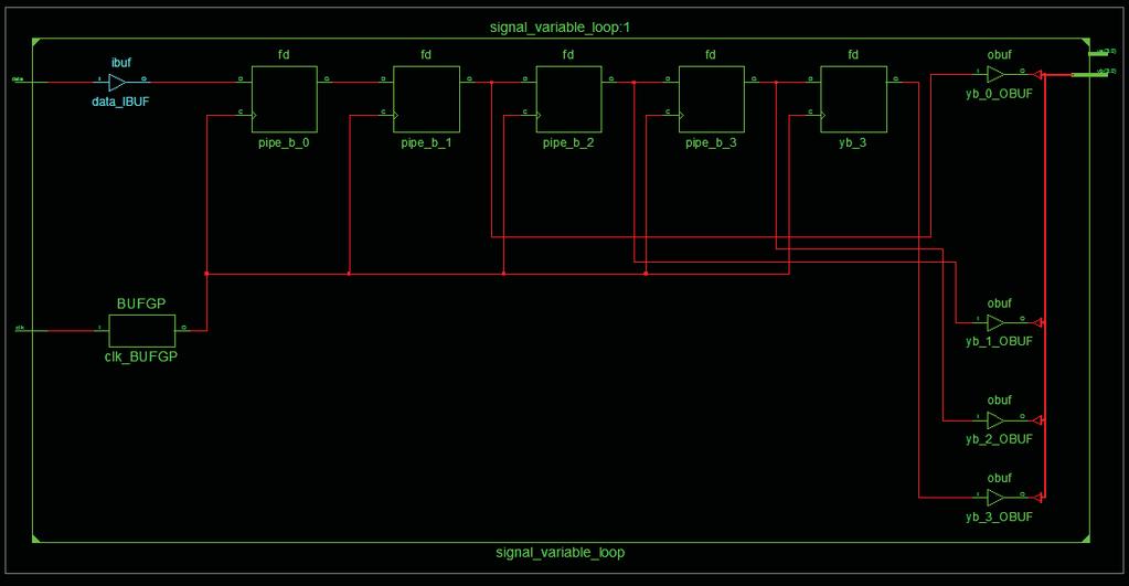
160 Signal Implementation 159
161 Signal Implementation 160
162 Sequential Statements assert 161
163 Statement: assert One of the reasons for writing models of computer systems is to verify that a design functions correctly We can test a model by applying sample inputs and checking that the outputs meet our expectations Assert statements can check that the expected conditions are met within the model 162
164 Statement: assert Assert makes possible to test function and time constraints on a VHDL model Using assert it is possible to test prohibited signal combinations or whether a time constraints is not being met It is not synthesizable 163
165 Statement: assert assert <boolean_expression> [report <string_expression> [severity <severity_level>]; -- severity must be a value of severity_level: -- NOTE, WARNING, ERROR, FAILURE -- report syntax -- [report <string_expression> [severity <severity_level>]; 164
166 Statement: assert If the boolean expression is not meet during simulation of a VHDL design, a message of a certain severity is sent to the designer There are four different severity (error) levels note warning error failure The message (from report <string_expression>) and error level are reported to the simulator and are usually displayed in the command window of the VHDL simulator 165
167 Statement: assert Severity (error) levels indicate the degree to which the violation of the assertion affects the operation of the model note: can be used to pass informative messages out assert (free_memory => low_mem_limit) report low in memory! severity note; 166
168 Statement: assert warning : can be used if an unusual situation arises in which the model can continue to execute, buy may produce unusual results assert (packet_length /= 0) report empty network packet received severity warning; 167
169 Statement: assert error : can be used to indicate that something has definitely gone wrong and that corrective action should be taken assert (clock_pulse_width => min_clock_width) report clock width problems! severity error; 168
170 Statement: assert failure : can be used to detect inconsistency that should never arise assert ((last_pos first_pos)+1 = number_entries) report inconsistency in buffer model! severity failure; 169
171 Statement: assert - Example Using assert to stop a simulation (test bench) process (clk) begin assert (now < 90 ns) report -- Stopping simulator -- severity FAILURE; end process; now: is defined in the VHDL standard, it contains the simulator s internal absolute time 170
172 Component Declaration Component Instantiation Hierarchical VHDL 171
173 The Role of Components in RTL VHDL Hierarchy in VHDL Components Divide & Conquer Each subcomponent can be designed and completely tested Create library of components (technology independent if possible) Third-party available components Code for reuse 172
174 Hierarchy in VHDL - Components High-Speed DDR ADC RS

175 Hierarchy in VHDL - Components 174
176 Components Components are design entities that are used in other design entities In order to use an entity within another entity, a component declaration is necessary for the entity to be used The interconnections between the component and the entity s signals is declared in the component instantiation 175
177 Component Declaration Define a sub-component within an entity (component) It can be declared in the architecture declarative part or in the package declaration (items declared in a package can be used in an entityarchitecture pair by using the library and the package names) Specify the component external interface: ports, mode and type and also the component name (it looks like an entity declaration) 176
178 Component Declaration Syntax: component comp_name [is] [generic (generic_interface_list);] port (port_interface_list); end component [component_name]; port_interface_list must be identical to that in the component s entity generic_interface_list do not need to be declared in the component declaration 177
179 Component Declaration Top Counter Inputs Nand2 Outputs BRAM D_FF 178
180 Component Declaration entity nand2 is port (a, b: in std_logic, z: out std_logic); end; architecture rtl of nand2 is end; entity top is port( ); end; achitecture structural of top is component nand2 port (a, b: in std_logic, z : out std_logic); end component; begin. end; 179
181 Component Instantiation component_label: component_name [generic map (generic_assocation_list)] port map (port_association_list); component_label it labels the instance by giving a name to the component to be instanced generic_assocation_list assign new values to the default generic values (given in the entity declaration) port_association_list associate the signals in the top entity/architecture with the ports of the component. There are two ways of specifying the port map: Positional Association / Name Association 180
182 Positional Association In positional association, an association list is of the form (actual1, actual2, actual3, actualn); Each actual in the component instantiation is mapped by position with each port in the component declaration That is, the first port in the component declaration corresponds to the first actual in the component instantiation, the second with the second and so on The I/Os on the component declaration, are called formals 181
183 Positional Association -- component declaration component NAND2 port (a, b: in std_logic, z: out std_logic); end component; formals -- component instantiation U1: NAND2 port map (S1, S2, S3); -- S1 associated with a -- S2 associated with b -- S3 associated with z actuals 182
184 Named Association In named association, an association list is of the form (formal1=>actual1, formal2=>actual2, formaln=>actualn); Component I/O Port Connected to Internal Signal or Entity I/O Port -- component declaration component NAND2 port (a, b: in std_logic; z: out std_logic); end component; -- component instantiation U1: NAND2 port map (a=>s1, z=>s3, b=>s2); -- S1 associated with a,s2 with b and S3 with z 183
185 Association Rules The type of the formal and the actual being associated must be the same The modes of the ports must conform the rule that if the formal is readable, so must the actual be. If the formal is writable so must the actual be If an actual is a port of mode in, it may no be associated with a formal of mode out or inout If the actual is a port of mode out, it may not be associated with a formal of mode in or inout If the actual is a port of mode inout, it may be associated with a formal of mode in, out or inout 184
186 Unconnected Outputs When a component is instanced, one of the outputs sometimes has to be unconnected This can be done using the keyword open architecture rtl of top_level is component ex4 port (a, b : in std_logic; q1, q2: out std_logic; end component; begin U1: ex4 port map(a=>a, b=>b, q1=>dout, q2=>open); end; 185
187 Unconnected inputs Leaving floating inputs is a very bad poor technique If an input on a component is not to be used, the signal should be connected to VCC or GND. VHDL 87: It is not permissible to map the input directly in the port map, an internal signal must be used 186
188 Unconnected inputs architecture rtl of top_level is component ex4 port (a, b: in std_logic; q1, q2: out std_logic; end component; signal gnd: std_logic; begin gnd <= 0 ; U1: ex4 port map(a=>gnd, b=>b, q1=>dout, q2=>open); end; 187
189 Unconnected inputs architecture rtl of top_level is component ex4 port (a, b : in std_logic; q1, q2: out std_logic; end component; begin U1: ex4 port map(a=> 0, b=>b, q1=>dout, q2=>open); end rtl; 188
190 component - Example entity GATING is port (A, CK, MR, DIN: in BIT; RDY, CTRLA: out BIT); end GATING; architecture STRUCT of GATING is component AND2 port( X, Y: in bit; Z: out bit); end component; component DFF port (D, CLOCK: in BIT; Q, QBAR: out BIT); end component; component NOR2 port ( end component; DA, DB: in BIT; DZ: out BIT); signal S1, S2: BIT; begin D1: DFF port map (A, CK, S1, S2); A1: AND2 port map (S2, DIN, CTRLA); N1: NOR2 port map (S1, MR, RD1); end STRUCT; 189
191 Generic Map generic map (generic_assocation_list); If generic components have been specified in the component to be instanced, their value can be changed during instantiation using the command generic map By using generics, it is possible to design components which can be parameterized Positional and named association can be used 190
192 component - Example ARCHITECTURE ejemplo OF regist_variable IS COMPONENT dff GENERIC ( width: POSITIVE); PORT (rst, clk: IN std_logic; d: IN STD_LOGIC_VECTOR(width-1 downto 0); q: OUT STD_LOGIC_VECTOR(width-1 downto 0)); END COMPONENT; CONSTANT width_8: POSITIVE:= 8; CONSTANT width_16: POSITIVE:= 16; CONSTANT width_32: POSITIVE:= 32; SIGNAL d8, q8: STD_LOGIC_VECTOR(7 DOWNTO 0); SIGNAL d16, q16: STD_LOGIC_VECTOR(15 DOWNTO 0); SIGNAL d32, q32: STD_LOGIC_VECTOR(31 DOWNTO 0); 191
193 component - Example (cont ) BEGIN FF8: dff GENERIC MAP(width_8) PORT MAP (rst, clk, d8, q8); FF16: dff GENERIC MAP(width_16) PORT MAP (rst, clk, d16, q16); FF32: dff GENERIC MAP(width_32) PORT MAP (rst=>rst,clk=>clk,d=>d32, q=>q32); END ejemplo; 192
194 Concurrent Statements generate 193
195 Generate Statements Concurrent statements can be conditionally selected or replicated using the generate statement Generate is a concurrent statement containing further concurrent statements that are to be replicated There are two forms of the generate statement: for-generate scheme: concurrent statements can be replicated a predetermined number of times if-generate scheme: concurrent statements can be conditionally elaborated 194
196 Generate Statements Generate statement resembles a macro expansion If the same component has to be instanced several times in the same architecture, it will be very effective to include the port map statement in a loop 195
197 for-generate Concurrent statements are repeated a predetermined number of times G_LABEL: FOR <identifier> IN <discrete_range> GENERATE [block_declarative_part] [begin] concurrent_statements; END GENERATE [G_LABEL]; The value in the discrete range must be globally static During the elaboration phase, the set of concurrent statements are replicated once for each value of the discrete range There is an implicit declaration for the generate identifier. No declaration is necessary for this identifier A label is required in the generate statement 196
198 for-generate entity reg_xx is generic (bus_w:integer := 32); port(clk, clr: in std_logic; d : in std_logic_vector (bus_w-1 downto 0); q : out std_logic_vector (bus_w-1 downto 0)); end reg_xx; architecture estructural of reg_xx is -- component declaration component dff is port (clk, clr, d, pr: in std_logic; q: out std_logic); end component; -- signal declaration signal gnd: std_logic; begin gnd <= '0'; -- component instantiation reg_xx: for i in d range generate bit: dff port map (clk=>clk, clr=>clr, d=>d(i), q=>q(i), pr=>gnd); end generate reg_xx; end estructural; 197
199 for-generate 198
200 for-generate Scheme entity FULL_ADD4 is port (A, B: in std_logic_vector(3 downto 0); CIN: in std_logic_vector; SUM: out std_logic_vector (3 downto 0); COUT: out std_logic); end FULL_ADD4; architecture FOR_GENERATE of FULL_ADD4 is component FULL_ADDER port (PA, PB, PC: in std_logic; PCOUT, PSUM: out std_logic); end component; signal CAR: std_logic_vector (4 downto 0); begin CAR(0) <= CIN; GK: for K in 0 to 3 generate FA:FULL_ADDER port map(car(k),a(k),b(k),car(k+1),sum(k)); end generate GK; COUT <= CAR(4); end FOR_GENERATE; 199
201 for-generate Scheme --- the previous generate statement is expanded to the --- following four blocks GK: block constant K: INTEGER := 3; begin FA: FULL_ADDER port map (CAR(K), A(K), B(K), CAR(K+1), SUM(K)); end block GK; GK: block constant K: INTEGER := 2; begin FA: FULL_ADDER port map (CAR(K), A(K), B(K), CAR(K+1), SUM(K)); end block GK;.... GK: block constant K: INTEGER := 0; begin FA: FULL_ADDER port map (CAR(K), A(K), B(K), CAR(K+1), SUM(K)); end block GK 200

202 for-generate Example 1 201
203 for-generate Scheme FPGA High-Speed ADC (Max104) x8 x8... IBUFDS IBUFDS DDR Clock 202
204 for-generate Scheme library IEEE; use IEEE.STD_LOGIC_1164.all; package VCOMPONENTS is.... I IB O -- IBUFDS: Differential Input Buffer -- Virtex-II/II-Pro, Spartan-3 -- Xilinx HDL Libraries Guide version 11.1i component IBUFDS generic map ( IOSTANDARD => "LVDS_25") port map ( O => O, -- buffer output I => I, -- Diff_p clock buffer input IB => IB -- Diff_n clock buffer input); end component;.... end package VCOMPONENTS; 203
205 for-generate Scheme abus_diff_sstl2: for i in 0 to 7 generate u_abus: IBUFDS --generic map ( IOSTANDARD => "SSTL2_II") port map( O => a_bus(i), I => a_bus_p(i), IB=> a_bus_n(i) ); end generate abus_diff_sstl2; pbus_diff_sstl2: for i in 0 to 7 generate u_pbus: IBUFDS --generic map ( IOSTANDARD => "SSTL2_II") port map( O => p_bus(i), I => p_bus_p(i), IB=> p_bus_n(i) ); end generate pbus_diff_sstl2; 204
206 if-generate Syntax: if-generate, concurrent statements can be condicionally elaborated G_LABEL: IF <condition> GENERATE [begin] concurrent_statements; END GENERATE [G_LABEL]; The if-generate statement allows for conditional selection of concurrent statements based on the value of an expression The expression must be a globally static expression The if-generate statement does not have else, elsif, endif 205
207 if-generate 206
208 if-generate Example 2 207
209 if-generate Another important use of conditional generate statements is to conditionally include or omit part of the design. Usually depending on the value of a generic constant. Typical examples: Logic added just for debugging purposes Additional processes or component instances used only during simulation 208
210 if-generate entity my_system is generic ( debug: boolean := true) port (... ); end entity my_system; architecture rtl of my_system is... begin... debug_comp: if debug generate... end generate debug_comp;... end architecture; 209
211 Finite State Machine 210
212 FSM Review A sequential circuit that is implemented in a fixed number of possible states is called a Finite State Machine (FSM). Finite state machines are critical for realizing the control and decision-making logic in a digital system. Finite state machines have become an integral part of the system design. VHDL has no formal format for modeling finite state machines. To model a finite state machine in VHDL certain guidelines must be followed. 211
213 State Machine General Diagram 1 Inputs Next State Logic Next State Current State Logic Current State Output Logic Outputs CLK RST 212
214 State Machine General Diagram 2 Inputs Next State Logic Next State Current State Logic Current State Output Logic Sync Output FFs Outputs CLK RST 213
215 State Machine Diagram 3 Sync Output FFs Outputs Inputs Next State Logic Next State Current State Logic Current State CLK RST 214
216 State Machine General Diagram 4 Sync Output FFs Output A Inputs Next State Logic Next State Current State Logic Current State.... Sync Output FFs Output Z CLK RST 215


217 State Machine VHDL General Flow Specification Understand the Problem Draw the ASM or State Diagram Define FSM Enumerated Type Define FSM Signals Select One Coding Style Write the Code 216
218 State Machine General Diagram Coding Style Current State Clocked Process Next State Logic Output Logic Style A (Comb) Style B Style C Style D Style E (Seq) Different processes Combined processes 217
219 State Machine: Declarative Part Declare an enumerated data type with values the states of the state machine: -- declare the states of the state-machine -- as enumerated type type FSM_States is(idle,start,stop_1bit,parity,shift); Declare the signals for the next state and current state of the state machine as signal of the enumerated data type already defined for the state machine: -- declare signals of FSM_States type signal current_state, next_state: FSM_States; The only values that current_state and next_state can hold are: IDLE,START,STOP_1BIT,PARITY,SHIFT 218
220 State Machine: Clocked Process The clocked process decides when the state machine should change state This process is activated by the state machine s clock signal Depending on the present state and the value of the input signals, the state machine can change state at every active clock edge Current state gets the value of the next state on the active edge of the clock Next state value is generated in the state transition process, depending on the values of current state and the inputs 219
221 State Machine: Combinatorial Process Assigns the output signals their value depending on the present state Next state logic and output logic is best modeled using case statements are better for this process All the rules of combinatorial process have to be followed to avoid generating unwanted latches For Mealy Machines if-then-else statement is used to create the dependency between the current state, the input signal and output signal 220
222 State Machine: Reset behavior Asynchronous reset: ensure that the state machine is always initialized to a known valid state, before the first active clock transition and normal operation commences No reset or a synchronous reset: there is no way to predict the initial value of the state register flipflops. It could power up and become permanently stuck in an uncoded state. 221
223 FSM Style Descriptions - Example X = 1 Moore FSM X = 0 S0 S1 Z = 0 Z = 1 X = 0 X = 1 Mealy FSM X = 1 Z = 1 X = 0 Z = 0 S0 S1 X = 0 Z = 1 X = 1 Z = 0 222
224 Style A - Moore State Machine Next State Logic Is process (state, X) begin case state is when S0 => if(x= 0 ) then next_state <= S0; else(x= 1 ) then next_state <= S1; end if; when S1 => if. next_state <=..;. end case; end process; Present State Logic process (clk, rst) begin if(rst = 1 ) then state <= S0; elsif (rising_edge(clk)) then state <= next_state; end if; end process; Output Logic process (state) begin case state is when S0 => Z <= 0 ; when S1 => Z <= 1 ; end case; end process; Os Clock Reset 223
225 Style A - Mealy State Machine Next State Logic Is Clock process (state, X) begin case state is when S0 => if(x= 0 ) then next_state <=S0; else(x= 1 ) then next_state <=S1; end if; when S1 => if. next_state <=..;. end case; end process; Present State Logic process (clk, rst) begin if(rst = 1 ) then state <= S0; elsif (rising_edge(clk)) then state <= next_state; end if; end process; Output Logic process (state, X) begin case state is when S0 => if (X = 0 ) then Z <= ; else Z <=... ; end if; when S1 => if (X = 1 ) then... ; else... ; end if; end case; end process; Os Reset 224
226 Style A - Synthesis Moore Mealy 225
227 Style B - Moore State Machine Is State, Next State and Output Logic process(clk, rst) begin if(rst = 1 ) then state <= S0; Z <= 0 ; elsif (rising_edge(clk)) then case state is when S0 => if (X= 0 ) then state <= S0; elsif (X= 1 ) then state <= S1; end if; Z <= 0 ; when S1 => if (X = 0 ) then... end if; Z <= 1 ; end case; end if; end process; Os Clock Reset 226
 then state <=... ; Z <=... ; elsif (X= 1 ) then state <=... ; Z <=... ; end if; when S1 => if (X = 0 ) then.")
228 Style B - Mealy State Machine State, Next State and Output Logic Is process(clk, rst) begin if(rst = 1 ) then state <= S0; Z <= 0 ; elsif (rising_edge(clk)) then case state is when S0 => if (X= 0 ) then state <=... ; Z <=... ; elsif (X= 1 ) then state <=... ; Z <=... ; end if; when S1 => if (X = 0 ) then... end if; end case; end if; end process; Os Clock Reset 227
229 Style B - Synthesis Moore Mealy 228
230 Style C - Moore State Machine Present State and Next State Logic Is process (clk, rst) begin if(rst = 1 ) then State <= S0; elsif (rising_edge(clk)) then case state is when S0 => if(x = 1 ) then state <=S1; end if; when S1 => if( X = 1 ) then state <=S0; end if; end case; end if; end process; Output Logic process (state) begin case state is when S0 => Z <= 0 ; when S1 => Z <= 1 ; end case; end process; Os Clock Reset 229
231 Style C - Mealy State Machine Present State and Next State Logic Output Logic Is process (clk, rst) begin if(rst = 1 ) then state <= S0; elsif (rising_edge(clk)) then case state is when S0 => if(x = 1 ) then state <=... ; end if; when S1 => if( X = 1 ) then state <=... ; end if; end case; end if; end process; process (state, X) begin case state is when S0 => if(x= 1 ) then Z <=... ; else Z <=... ; end if; when S1 => if(x= 1 ) then Z <=... ; else Z <=... ; end if; end case; end process; Os Clock Reset 230
232 Style C - Mealy State Machine Moore Mealy 231
233 Style D - Moore State Machine Next State and Output Logic Os Is process (state, X) begin next_state <= state; case state is when S0 => if(x = 1 ) then next_state <=S1; end if; Z <= 0 ; when S1 => if( X = 1 ) then next_state <=S0; end if; Z <= 1 ; end case; end process; Present State Logic process (clk, rst) begin if(rst = 1 ) then state <= S0; elsif (rising_edge(clk)) then state <= next_state; end if; end process; Clock Reset 232
234 Style D - Mealy State Machine Next State and Output Logic Os Is process (state, X) begin next_state <= state; Z <=... ; case state is when S0 => if(x = 1 ) then next_state <=... ; Z <=... ; end if; when S1 => if( X = 1 ) then next_state <=... ; Z <=... ; end if; end case; end process; Present State Logic process (clk, rst) begin if(rst = 1 ) then state <= S0; elsif (rising_edge(clk)) then state <= next_state; end if; end process; Clock Reset 233
235 Style D - Mealy State Machine Moore Mealy 234
236 Style E - Moore State Machine Next State Logic Is process (state, X) begin case state is when S0 => if(x= 0 ) then next_state <=S0; else(x= 1 ) then next_state <=S1; end if; when S1 => if. next_state <=..;. end case; end process; Present State Logic process (clk, rst) begin if(rst = 1 ) then state <= S0; elsif (rising_edge(clk)) then state <= next_state; end if; end process; Seq. Output Logic process (clk, rst) begin if(rst = 1 ) then state <= S0; elsif (rising_edge(clk)) then case state is when S0 => Z <= 0 ; when S1 => Z<= 1 ; end case; end process; Os Clock Reset 235
237 Xilinx XST State Encoding Techniques XST supports the following state encoding techniques: Auto-State Encoding One-Hot Encoding Gray State Encoding Compact State Encoding Johnson State Encoding Sequential State Encoding Speed1 State Encoding User State Encoding 236
238 XST State Encoding Techniques FSM_ENCODING (FSM Encoding Algorithm) Algorithm VHDL Syntax Declare the attribute as follows: attribute fsm_encoding: string; Specify as follows: attribute fsm_encoding of {entity_name signal_name }: {entity signal} is "{auto one-hot compact sequential gray johnson speed1 user}"; The default is auto 237
239 syn_encoding - Synplify Override the default FSM Compiler encoding for a FSM Possible values: Default: assign an encoding style based on the number of states: Sequential for 0-4 enumerated types One-hot for 5-24 enumerated types Gray for > 24 enumerated types Sequential: One-hot: Gray: Safe: default encoding + reset logic to a known state 238

240 syn_encoding - Synplify Syntax (source code) -- declare the (state-machine) enumerated type type my_state_type is (SEND, RECEIVE, IGNORE, HOLD, IDLE); -- declare signals as my_state_type type signal nxt_state, current_state: my_state_type; -- set the style encoding Attribute syn_encoding: string; attribute syn_encoding of current_state: signal is one-hot; syn_encoding in SCOPE 239
241 type_encoding_style Precision Possible values: Binary Onehot Twohot Gray Random -- Declare the (state-machine) enumerated type type my_state_type is (SEND, RECEIVE, IGNORE, HOLD, IDLE); -- Set the TYPE_ENCODING_STYLE of the state type attribute TYPE_ENCODING_STYLE of my_state_type:type is ONEHOT; 240
242 type_encoding - Precision type_encoding allows to fully control the state encoding hard code the state code in the source code -- Declare the (state-machine) enumerated type type my_state_type is (SEND, RECEIVE, IGNORE, HOLD, IDLE); -- Set the type_encoding attribute attribute type_encoding of my_state_type:type is ("0001","01--","0000","11--","0010"); State Table Note: LeonardoSpectrum allows to use -. It can be used to reduce the size of the circuit 241
243 State Machine Coding: Residual States If one-hot state coding is not used, the maximum number of states is equal to 2**N, where N is the vector length of the state vector In state machines where not all the states are used, there are three options: Let chance decide what is to happen if the machine goes to an undefined state Define what is to happen if the state machine goes to an undefined state by ending the case statement with when others Define all the possible states in the VHDL code 242
244 State Machine Coding: Simulation 243

245 State Machine Coding: Synthesis Synplify FSM Report: 244
246 State Machine Coding: Synthesis XST FSM Report: ============================================== * Advanced HDL Synthesis * ============================================== Analyzing FSM <FSM_0> for best encoding. Optimizing FSM <rs232_tx/tx_current_state/fsm> on signal <tx_current_state[1:3]> with sequential encoding State Encoding idle 000 start 001 shift 010 parity 011 stop_1bit
247 FSM Example Realizar la descripción en VHDL de un receptor y transmisor serie tipo RS-232. El dato recibido y el dato a transmitir debe tener el siguiente formato: 1 bit de start 8 bits de datos Paridad programable: paridad/no paridad, par/impar 1 bit de stop Frecuencia de transmisión por defecto es de 9600 Bauds, pero el código debe permitir también otras frecuencias como: 4800, 38400, Bauds. 246
248 FSM Example RS-232 Tx format 247
249 FSM Example Parity 00 Dato(7:0) 01 DatoSerie SysClock DatoSent E1 E0 Reg Desplaza miento 10 StartTx SysReset FSM RS232 Tx Controller Done StartStopBit Sel1, Sel0 248
250 Subprogramas 249
251 Subprograms Sequence of statements that can be executed from multiple locations in the design Provide a method for breaking large segments of code into smaller segments Types of subprograms: Functions: used to calculate and return one value Procedures: used to define an algorithm which affects many values or no values 250
252 Subprograms Function - Return only one value - Executed in zero simulation time - Can be invoked from an expression Procedure - Return zero or several values - Can or can not be executed in zero simulation time (wait statement) 251
253 Function Provides a method of performing simple algorithms Produce a single return value Invoked by an expression Can not modify parameters. Only mode allowed: IN (read only) wait statements are NOT permitted in a function 252
254 Function Syntax Declarative part function function_name(parameters_list)return return_type is function_declarations; begin sequential_statements; return simple_value; end [function] [function_name]; Behavioral part 253
255 Function Parts - Definitions [function_declarations] -- the only class declarations allowed are: Variables Constants <parameters_list> - mode in only - signals only <sequential_statements> - sequential instructions only - always has to end with a return statement 254
256 Function Key Concepts Variables can be used to accumulate results or hold intermediate values. But, variables declared within the function do not keep the value between executions Initial values assigned to variables are synthesizable Function can have more than one return, however just one is executed It is useful to declare the parameters as undefined for a general use of the function 255
257 Function Example 1 package my_pack is function max(a,b: in std_logic_vector) return std_logic_vector; end package; package body of my_pack is function max(a,b: in std_logic_vector) return std_logic_vector is begin if a> b then return a; else return b; end if; end function; end package body; 256
258 Function Example 1 library ieee; use ieee.std_logic_1164.all; package my_pack is function max(a,b: in std_logic_vector) return std_logic_vector; end package; package body my_pack is function max(a,b: in std_logic_vector) return std_logic_vector is begin if a> b then return a; else return b; end if; end function; end package body; 257
259 Function Usage - Example 1 -- use of the function declared in the package use work.my_pack.all;... entity example is port(...); end; architecture beh of example is begin... q_d1d2 <= max(d1,d2); -- concurrent call process(d3,d4) begin q_d3d4 <= max(b=>d3, a=>d4); -- sequential call end process; end; Package holding function declaration and behavior Parameter passing list: by position Parameter passing list: by name Note: d1, d2, data and g have to be std_logic_vector type 258
260 Function Example 2 -- convert Boolean to Bit function bool_to_bit(b:boolean) return bit is begin if b then return '1'; else return '0'; end if; end function bool_to_bit; 259
261 Function Example 3 function sehctam_tnuoc (a, b: bit_vector) return natural is variable va : bit_vector(a'length-1 downto 0):= a; variable vb : bit_vector(b'length-1 downto 0):= b; variable cnt: natural := 0; begin assert va'length = vb'length report the vectors have different size severity failure; for i in va'range loop if va(i) = vb(i) then cnt := cta + 1; end if; end loop; return cnt; end funciton; 260
262 Function Example 4 -- FUNCTION BIN2GRAY(VALUE) -- Used to convert Binary into Gray-Code function bin2gray(value:std_logic_vector)return std_logic_vector is variable grayval:std_logic_vector((value'length-1) downto 0); variable result: std_logic_vector((value'length-1) downto 0); begin l_oop:for i in 0 to (value'length-1) loop if(i=value'length-1) then grayval(i) := value(i); else grayval(i) := value(i+1) xor value(i); end if; end loop l_oop; result := grayval; return result; end function bin2gray; 261
263 Function Example 5 -- integer to bit_vector conversion -- result'low is the lsb function to_vector (nbits: positive; int_val: natural) return bit_vector is variable m1: natural := 0; variable result:bit_vector(nbits-1 downto 0):=(others => '0'); begin m1 := int_val; for j in result'reverse_range loop if (m1/mod2) = 1 then result(j) := '1'; else result(j) := '0'; end if; m1 := m1/2; end loop m1; return result; end function to_vector; 262
264 Procedure Provides a method of performing complex algorithms May produce multiple return (output) values Invoked by a statement Can affect input parameters Parameter s mode: IN: read only OUT: write only INOUT: read/write 263
265 Procedure Syntax Declarative part procedure proced_name (parameter_list) is [procedure_declarations] begin sequential_statements; end [procedure] [proced_name]; Behavioral part 264
266 Procedure Definitions <procedure_declarations> -- the only class declarations allowed are: Variables Functions Constants Types <parameter_list> in mode: to receive values out mode: to return values inout mode: to receive/return values Parameters can be signals, variables and constants. By default in = constant, out = variable Can return as many values as are needed using the out parameters 265
267 Procedure Calls Can be used in sequential or concurrent statements areas Concurrent calls are activated by changes in any signal associated with a parameter of mode IN or INOUT Sequential calls is executed whenever the procedure is encounter during the execution of the sequential code Passing parameter list: Association by name Association by position 266
268 Procedure Example 1 procedure calc(a,b: in integer; avg, max: out integer) is begin avg<= (a+b)/2; if a>b then max<=a; else max<=b; end if; end calc; 267
269 Procedure Example 2 -- sum, cout as variables procedure full_adder (a,b,c: in bit; sum, cout: out bit) is begin sum := a xor b xor c; cout := (a and b) or (a and c) or (b and c); end full_adder; 268
270 Procedure Example 3 -- sum, cout as variables procedure full_adder(a,b,c:in bit; signal sum, cout: out bit)is begin sum <= a xor b xor c; cout<= (a and b) or (a and c) or (b and c); end full_adder; 269
271 Procedure Example 3 entity adder4 is port ( a,b : in bit_vector(3 downto 0); cin : in bit; sum : out bit_vector(3 donwto 0); cout: out bit); end entity; architecture behavioral of adder4 is begin process (a, b, cin) variable result: bit vector(3 downto 0); variable carry : bit: begin full_adder(a(0), b(0), cin, result(0), carry); full_adder(a(1), b(1), carry, result(1), carry); full_adder(a(2), b(2), carry, result(2), carry); full_adder(a(3), b(3), carry, result(3), carry); sum <= result; cout <= carry; end process; end behavioral; 270
272 Procedure Example 4 architecture rtl of ex2 is procedure calc (a,b: in integer; avg, max: out integer) is begin avg:= (a+b)/2; if a>b then max:=a; else max:=b; end if; end calc; begin calc(d1,d2,d3,d4); -- concurrent call. ok? process(d3,d4) variable a,b: integer; begin calc(d3,d4,a,b); -- sequential call. ok? q3<=a; q4<=b;... end process; end; 271
273 Procedure Example 4 architecture rtl of ex3 is procedure calc(a,b:in integer; signal avg, max:out integer)is begin avg<= (a+b)/2; if a>b then max<=a; else max<=b; end if; end calc; begin calc(d1,d2,d3,d4); -- concurrent call. ok? process(d3,d4) variable a,b: integer; begin calc(d3,d4,a,b); -- sequential call. ok? q3<=a; q4<=b;... end process; end; 272
274 Procedure Example 5 procedure echo(constant str : in string) is variable l: line; begin write(l, string'("<")); write(l, time'(now)); write(l, string '("> ")); write(l, str); writeline(output,l); end echo; 273
275 Procedure Example procedure echo_now(constant str : in string) is variable l : line; begin write(l, str); write(l, <--")); write(l, time'(now)); write(l, string'("--> ")); writeline(output, l); end echo_now;; 274
276 Subprograms Overloading When two or more subprograms have the same name but different types in the list of parameters function max (a, b: in std_logic_vector) return std_logic_vector); function max (a, b: in bit_vector) return bit_vector); function max (a, b: in integer) return integer; 275
277 Package 276
278 Package Syntax package <package_name> is [subprograma_declarations]; [constant_declarations]; [type_declarations]; [component_declarations]; [attribute_declarations]; [attribute_specifications]; end <package_name>; package body <package_name> is [subprogram_bodies]; [internal_subprogram_declarations]; [internal_constant_declaration]; [internal_type_declaration]; end <package_name>; 277
279 Package A package declaration contains a set of declarations that may possible be shared by many design units. Common declarations are constants, functions, procedures and types A package body contains the hidden details of a package, such as the behavior of the subprograms Items declared in a package can be accessed by other design unit by using the library and use clauses 278
280 Declaring Subprograms in Packages -- package declaration package my_package is constant word_size: positive:=16; subtype word is bit_vector (word_size-1 downto 0); subtype address is bit_vector(address_size-1 downto 0); type status_value is (halted, idle, fetch, mem_read, mem_wr, io_read); function int_to_bit_vector (int_valor: integer) return bit_vector; end my_package; Function Declaration -- package body package body my_package is function int_to_bit_vector (int_vector: integer) return bit_vector is Function Body begin end int_to_bit_vector; end my_package; 279
281 Package.vhd File library ieee; use ieee.std_logic_1164.all; -- package declaration package my_pack is constant width: integer := 8; function max(a, b: in std_logic_vector) return std_logic_vector; end; -- package body package body my_pack is function max(a, b: in std_logic_vector) return std_logic_vector is begin if a> b then return a; else return b; end if; end; end; 280
282 Package Usage library ieee; use ieee.std_logic_1164.all; use work.my_pack.all; -- make the package available entity package_test_2 is port(d1,d2,d3: in std_logic_vector(width-1 downto 0); z: out std_logic_vector(width-1 downto 0); q: out std_logic_vector(width-1 downto 0)); end; architecture beh of package_test_2 is begin q <= max(d1,d2); -- concurrent call of the function process(d2,d3) begin z <= max(d3, d2); -- sequential call of the function end process; end; 281
283 Package Common Usage package my_pack is -- constants declarations constant bus_width : natural:=2; -- component declaration component bcd_7segm is port( led_outs : out std_logic_vector(6 downto 0); bcd_inps : in std_logic_vector(3 downto 0) ); end component; component mux is port( inf_inputs: in std_logic_vector(3 downto 0); sel : in std_logic_vector(1 downto 0); output : out std_logic); end component; end package my_pack; 282
284 Package Common Usage library ieee; use ieee.std_logic_1164.all; use work.my_pack.all; -- make the package available entity bcd_7seg_top is port ( ); end; architecture beh of package_test_2 is begin U1: bcd_7segm port map (... ); U2: mux port map (... );... end beh; 283
285 Package Common Usage library ieee; use ieee.std_logic_1164.all; use work.my_pack.all; -- make the package available entity bcd_7seg_top is port ( ); end; architecture beh of package_test_2 is begin U1: bcd_7segm port map (... ); U2: mux port map (... );... end beh; 284
286 Validation 285
287 Verification It s an IMPORTANT part of the design process: how de I know that the design works as expected? It s IMPORTANT/NECESSARY to verify the behavior of the design in at least one of following parts of the design process: Functional Verification / Pre-synthesis Verification Post-synthesis Timing Verification / Post-Place & Route Verification 286
288 Verification Where? Synthesis & Optimization Post_Synthesis Verification Compilation Functional Verification Place & Route Timing Verification 287
289 Verification Where?? Functional Verification / Pre-synthesis Verification: Where most errors can and should be found Use this verification ALWAYS Post-synthesis Verification: Not necessary unless several synthesis attributes were used and it s necessary to verify the behavior after synthesis Timing Verification / Post-Place & Route Verification: Necessary in high frequency designs, in the order of >100MHz Very slow process (very long verification time) 288
290 Verification Test Bench Test bench a VHDL model which generates stimulus waveforms to be used to test a digital circuit described in VHDL 289
291 Test Bench - Overview A model used to exercise and verify the correctness of a hardware design Besides synthesis, VHDL can also be used as a Test Language Very important to conduct comprehensive verification on your design To simulate your design you need to produce an additional entity and architecture design 290
292 Test Bench It has three main purposes: To generate stimulus for simulation To apply this stimulus to the entity under test and to collect output responses To compare output responses with expected values Test bench should be created by a DIFFERENT engineer than the one who created the module under test 291
293 Test Bench Test Bench Stimulus Signals Device Under Test (DUT) Tested Signals 292
294 Test Bench - Components TB entity: Empty declaration TB architecture: Component declaration Local signal declaration Component instantiation Stimulus statements Check values statements 293


295 Test Bench Components Simulator Test Bench Processes DUT Data Generation Comb. Logic Comb. Logic Comb. Logic Clock Generation Reset Generation Data Verification 294

296 Test Bench Simulation Results 295
297 Test Bench - Components library ieee; use ieee.std_logic_1164.all; entity test_my_design is end test_my_design; Define library, same as in VHDL source code VHDL model without entity interface architecture testbench of test_my_design is component my_design is port (a,b : in std_logic; Component declaration of the x,y : out std_logic); device to test end component; signal as,bs : std_logic:= 1 ; signal xs,ys : std_logic; begin uut : my_design port map (a=>as, b=>bs, x=>xs, y=>ys); as <= not(as) after 50 ns; process begin bs <= '1'; wait for 75 ns; bs <= '0'; wait for 25 ns; end process; end testbench; Define signal names Instantiated UUT in test bench Define the stimulus of the test 296
298 Test Bench VHDL Template library ieee; use ieee.std_logic_1164.all; -- TB entity declaration del TB (empty entity) entity testbench is end testbench; -- architecture declaration architecture tb of testbench is -- component declaration: component to test component device_under_test port(list_of_ports); end component; -- local signal declarations. Used to: -- stimulate the DUT s inputs -- test the DUT s outputs <local_signal_declarations;> 297
299 Test Bench VHDL Template (cont) begin -- component instantiation: -- associate the top-level (TB) -- signals to their equivalent DUT s signals DUT: entity_under_test port map( list_of_ports); -- stimulus statements for the input signals. -- values are assigned at different times per each input generate_input_waveforms; -- ouptut signals check end tb; monitor_output_statements; 298
300 Test Bench Use of wait The wait statement can be located anywhere between begin and end process Basic Usages: wait for time; wait until condition; wait on signal_list; wait; 299
301 Test Bench Use of wait 1 process... J <= 1 ; wait for 50 ns;-- process is suspended for 50 ns after J is assigned to 1 end process; process... wait until CLK = 1 ;-- sync with CLK rising edge before -- continuing of simulation... end process; 300
302 Test Bench Use of wait 2 process... wait on A until CLK = 1 ;-- the process is resumed -- after a change on A signal, -- but only when the value of... end process; -- the signal CLK is equal to process rst <= 1 ; wait for 444 ns; rst <= 0 ; wait; -- used without any condition, -- the process will be suspended -- forever end process; 301
303 Test Bench Clock Generation 1 architecture testbench of test_my_design is signal clk_50 : std_logic := 1 ; signal clk_75 : std_logic := 0 ; constant clk_period : time := 100 ns; constant h_clk_period: time := 50 ns; begin -- case 1: concurrent statement clk_50 <= not(clk_50) after h_clk_period;-- 50% duty -- case 2: sequential statement clk_75_proc: process begin clk_75 <= '1'; wait for 75 ns; -- 75% duty clk_75 <= '0'; wait for 25 ns; end process clk_75_proc; end testbench; clk_50 clk_
304 Test Bench Clock Generation 2 architecture testbench of test_my_design is signal clk: std_logic := 0 ; constant period: time := 40 ns; begin diff_duty_clk_cycle: process begin clk <= 0 ; wait for period * 0.60; clk <= 1 ; wait for period * 0.40; -- 60% duty cycle end process diff_duty_clk_cycle;... end architecture testbench; 303
305 Test Bench Clock Generation 3 architecture testbench of test_my_design is signal clk: std_logic:= 0 ; constant half_period: time := 20 ns; begin clk_cycle: process begin clk <= 0 ; wait for half_period; -- the clock will toggle clk <= 1 ; wait for half_period; -- as long as the simulation -- is running end process clk_cycle;... end architecture testbench; 304
306 Test Bench Data Generation Avoid race conditions between data and clock Applying the data and the active edge of the clock simultaneously might cause a race condition To keep data synchronized with the clock while avoiding race condition, apply the data at a different point in the clock period that at the active edge of clock 305
307 Test Bench Data Generation 1 Example of Data generation on inactive clock edge Clock generation process Data generation process clk_gen_proc: process begin Clk <= 0 ; wait for 25 ns; clk<= 1 ; wait for 25 ns; end process clk_gen_proc; data_gen_proc: process while not (data_done) loop DATA1 <= X1; DATA2 <= X2;... wait until falling_edge(clk); end loop; end process data_gen_proc; 306
308 Test Bench Data Generation 2 Relative time: signal waveforms that are specified to change at simulation times relative to the previous time, in a time accumulated manner architecture relative_timing of mytest is signal Add_Bus : std_logic_vector(7 downto 0); begin patt_gen_proc: process begin Add_Bus <= ; wait for 10 ns; Add_Bus <= ; wait for 10 ns; Add_Bus <= ; wait for 10 ns; end process patt_gen_proc;... end relative_timing; X 00 X 05 X AA X
309 Test Bench Data Generation 3 Absolute time: signal waveforms that are specified to change at simulation times absolute since the moment that the simulation begin architecture absolute_timing of testbench is signal A_BUS : std_logic_vector(7 downto 0); begin A_BUS <= , after 10 ns, after 20 ns; -- etc.... end absolute_timing; X 00 X 05 X 0A
310 Test Bench Data Generation 3 Absolute time: signal waveforms that are specified to change at simulation times absolute since the moment that the simulation begin -- 2 bits test pattern begin test0 <= 0, 1 after 10 ns, 0 after 20 ns, 1 after 30 ns; test1 <= 0, 1 after 20 ns;... test0 test1 309
311 Test Bench Data Generation 4 architecture array_usage of in_test_benches is signal Add_Bus : std_logic_vector(7 downto 0); -- type & signal declarations: 5 data for 8 bits type stimulus is array (0 to 4) of std_logic_vector (7 downto 0); constant DATA : stimulus := ( , -- declare the stimulus , -- as an array , -- these values will be , -- used to stimulate the ); -- inputs begin stim_proc: process begin for i in 0 to 4 loop -- for loop that assign Add_BUS <= DATA(i); -- to Add_Bus a new value wait for 10 ns; -- from stimulus every 10ns end loop; end process stim_proc;... end array_usage; 310
312 Test Bench Data Generation 5 architecture array_usage of in_test_benches is -- same declarations as previous example begin process begin for i in 0 to 4 loop Add_BUS <= DATA(i); for k in 1 to 7 loop wait until rising_edge(clk); end loop; wait until falling_edge(clk); end loop; end process;... end array_usage; In this case each pattern in the sequence is held for how many clock cycles??? 311
313 Test Bench Reset Generation -- asynchronous desassert reset reset: process begin rst <= 1 ; wait for 23 ns; rst <= 0 ; wait for 1933 ns; rst <= 1 ; wait for 250 ns; rst <= 1 ; wait; end process; 312
314 Test Bench Reset Generation -- synchronous desassert reset sreset: process begin rst <= 1 ; for i in 1 to 5 loop wait until clk = 1 ; end loop; rst <= 0 ; end process; 313
315 Test Bench Simple Ex. Decoder 2:4 entity dcd_2_4 is port (in1 : in std_logic_vector (1 downto 0); out1 : out std_logic_vector (3 downto 0)); end dcd_2_4; -- architecture dataflow of dcd_2_4 is begin with in1 select out1 <= "0001" when "00", "0010" when "01", "0100" when "10", "1000" when "11", "0000" when others; end dataflow; 314
316 Test Bench Simple Ex. Decoder 2:4 -- Test Bench to exercise and verify -- correctness of DECODE entity entity tb2_decode is end tb2_decode; architecture test_bench of tb2_decode is type input_array is array(0 to 3) of std_logic_vector(1 downto 0); constant input_vectors: input_array := ("00", "01", "10", "11"); signal in1 : std_logic_vector (1 downto 0); signal out1 : std_logic_vector (3 downto 0); component decode port ( in1 : in std_logic_vector(1 downto 0); out1: out std_logic_vector(3 downto 0)); end component; 315
317 Test Bench Simple Ex. Decoder 2:4 Stimulus to the Inputs and Component Instantiation: begin decode_1: decode port map( in1 => in1, out1 => out1); apply_inputs: process begin for j in input_vectors range loop in1 <= input_vectors(j); wait for 50 ns; end loop; end process apply_inputs; Component Instantiation Inputs Stimulus and Outputs port map Data generation 316
318 Test Bench Simple Ex. Decoder 2:4 (1) Data verification: Input stimulus test_outputs: process begin wait until (in1 = "01"); wait for 25 ns; assert (out1 = "0110") report"output not equal to 0110" severity ERROR; -- check the other outputs end process test_outputs; Wait on certain time Check the output 317
319 Test Bench Elaborated: Decoder 2:4 (2) -- Test Bench to exercise and verify -- correctness of DECODE entity entity tb3_decode is end tb3_decode; architecture test_bench of tb3_decode is type decoder_test is record in1: std_logic_vector(1 downto 0); out: std_logic_vector(3 downto 0); end record; type test_array is array(natural range <>) of decoder_test; constant test_data: test_array := (("00", "0001"), ("01", "0010"), ("10", "0100"), ("11", "1000")); -- same component declaration as before signal in1_tb : std_logic_vector(1 downto 0); signal out1_tb: std_logic_vector(3 downto 0); 318
320 Test Bench Elaborated: Decoder 2:4 (3) begin decode_1: decode port map( in1 => in1_tb, out1 => out1_tb); apply_in_check_outs: process begin for j in test_data range loop in1_tb <= test_data(j).in1); wait for 50 ns; assert (out1_tb = test_data(j).out1) report "Output not equal to the expected value, error en indice & integer image(j); severity ERROR; end loop; end process apply_in_check_outs; 319
321 Test Bench Elaborated: Decoder 2:4 (4) begin apply_inputs: process begin for j in test_data range loop in1 <= test_data(j).in1); wait for 50 ns; end loop; end process apply_inputs; data_verif: process begin wait for 25 ns; assert (out1 = test_data(j).out1) report "Output not equal to the expected value" severity ERROR; wait for 50 ns; end process data_verif; 320
322 Test Bench Elaborated 2: Decoder 2:4 (5) entity dcd_2_4 is port (in1 : in std_logic_vector(1 downto 0); clk : in std_logic ; out1 : out std_logic_vector(3 downto 0)); end dcd_2_4; architecture dataflow of dcd_2_4 is signal out1_i: std_logic_vector (3 downto 0); begin with in1 select out1_i <= "0001" when "00", "0010" when "01", "0100" when "10", "1000" when "11", "0000" when others; reg_proc: process(clk) begin if(rising_edge(clk)) then out1 <= out1_i; end if; end process reg_proc; end dataflow; 321
323 Test Bench Example 74LS
324 Test Bench Example 74LS
325 Test Bench Example 74LS194 (1) -- example of a 4-bit shift register -- LS194 4-bit bidirectional universal shift register library ieee; use ieee.std_logic_1164.all; entity ls194 is port( clk,mr_n,s0,s1,dsr,dsl_ser: in std_logic; p : in std_logic_vector(3 downto 0); q : out std_logic_vector(3 downto 0) ); end ls194; 324
326 Test Bench Example 74LS194 (2) architecture behav of ls194 is signal temp: std_logic_vector(3 downto 0); signal ctrl: std_logic_vector (1 downto 0); begin ctrl <= s0 & s1; shift_proc: process(clk, mr_n ) begin if (mr_n = '0') then temp <= (others => '0'); elsif (rising_edge(clk)) then case ctrl is when "11" => temp <= p; when "10" => temp <= dsr & temp(3 downto 1); when "01"=> temp <= temp(2 downto 0) & dsl; when others => temp <= temp; end case; end if; end process; q <= temp; end behav; 325
327 Test Bench Example 74LS194 (3) -- example of test bench to test the ls194 library ieee; use ieee.std_logic_1164.all; entity test_bench is end test_bench; architecture tb of test_bench is component ls194 is port( clk,mr_n,s0,s1,dsr,ds: in std_logic; p : in std_logic_vector(3 downto 0); q : out std_logic_vector(3 downto 0)); end component; -- internal signals signal clk_tb: std_logic:= 1 ; signal s0_tb, s1_tb, mr_tb_n, dsr_tb, dsl_tb: std_logic:= '0'; signal p_tb, q_tb : std_logic_vector (3 downto 0); 326
328 Test Bench Example 74LS194 (4) -- constant declarations constant clk_period: time := 200 ns; begin -- component instantiation U1: ls194 port map( clk => clk_tb, mr_n => mr_tb_n, s0 => s0_tb, s1 => s1_tb, dsr => dsr_tb, dsl => dsl_tb, p => p_tb, q => q_tb); -- clock generation clk_tb <= not clk_tb after clk_period/2; 327
329 Test Bench Example 74LS194 (5) main_proc: process begin -- check_init_proc wait for 10 ns; assert q_tb = "0000" report " Initialization Error " severity ERROR; wait for 20 ns; mr_tb_n <= '1 ; -- check synchronous load s0_tb <= 1 ; s1_tb <= 1 ; p_tb <= "0110"; 328
330 Test Bench Example 74LS194 (6) wait for clk_period; -- wait until falling edge clk_tb wait until clk_tb = 0 ; assert q_tb = "0110" report " Load Error " severity ERROR; -- check shift left s0_tb <= 0 ; -- wait until falling edge clk_tb wait until clk_tb = 0 ; assert q_tb = "1100" report " Error: Shift left Failed " severity ERROR; 329
331 Test Bench Example 74LS194 (7) -- three more shift left for i in 0 to 2 loop if i = 1 then dsl_tb <= 0 ; else dsl_tb <= 1 ; end if; wait until clk_tb = 0 ; end loop; assert q_tb = "0101" report " Error: serial left shift failed " severity ERROR; wait; end process; end tb; 330
332 Test Bench Example 74LS194 (8) 331
333 Test Bench - Conclusion TB is done in VHDL code Emulate the Hardware Use all the power of VHLD There is no size limit TB is the top-level unit Usually is more complex than the design itself 332
334 Attributes 333
335 Attributes It s a way of extracting information from a type, from the values of a type or it might define new implicit signals from explicitly declared signals It s also a way to allow to assign additional information to objects in your design description (such as data related to synthesis) Pre-defined Attributes User-defined/Synthesis Attributes Simulation & Synthesis Only Simulation 334
336 Predefined Attributes Syntax: <data_object/type/block> attribute_identifier; 335
337 Array Attributes Array attributes are used to obtain information on the size, range and indexing of an array It s good practice to use attributes to refer to the size or range of an array. So, if the size of the array is change, the VHDL statement using attributes will automatically adjust to the change 336
338 Array Attributes Array Attributes Value Related A left A right Returns the left-most bound of a given type or subtype Returns the left-most bound of a given type or subtype A high Returns the upper bound of a given type or subtype A low A length A ascending Returns the lower bound of a given type or subtype Return the length (number of elements of an array) Return a boolean true value of the type or subtype declared with an ascending range 337
339 Array Attributes Array Attributes Range Related A range A reverse_range Returns the range value of a constrained array Returns the reverse value of a constrained array 338
340 Array Attributes - Examples type bit_array_1 is array (1 to 5) of bit; variable L: integer:= bit_array_1'left; -- L = 1 variable R: integer:= bit_array_1'right; -- R = 5 type bit_array_2 is array (0 to 15) of bit; variable H: integer:= bit_array_2'high; -- H = 15 type bit_array_3 is array (15 downto 0) of bit; variable L: integer:= bit_array_3'low; -- L = 0 variable LEN: integer:= bit_array_3'length; -- L = 16 variable A1: boolean := bit_array_1'ascending;-- A1 = true variable A2: boolean := bit_array_3'ascending;-- A2 = false type states is (init, reset, cnt, end); signal Z, Y: states; Z <= estados'left; -- Z = init Y <= estados'right; -- Y = end 339
341 Array Attributes range and reverse_range usage: variable w_bus: std_logic_vector(7 downto 0); then: w_bus range will return: 7 downto 0 and: w_bus reverse_range will return: 0 to 7 340
342 Array Attributes function parity(d: std_logic_vector) return std_logic is variable result: std_logic := '0'; begin for i in D'range loop result := result xor D(i); end loop; return result; end parity; 341
343 Array Attributes for i in D'range loop for i in D reverse_range loop for i in D low to D high loop for i in D high to D low loop 342
344 Attributes of Signals Attributes that return information about signals such as previous value, value change, etc. Attributes of Signals S event S active True if there is an event on S in the current simulation cycle, false otherwise True if there is an transaction S in the current simulation cycle, false otherwise S last_event The time interval since the last event on S S last_active S last_value The time interval since the last transaction on S The value of S just before the last event on S 343
345 Attributes of Signals - Example process constant setup_time: time :=1.2 ns; begin wait until clk = 0 ; assert (data'stable(setup_time)) report Setup Violation" severity warning; end process; 344
346 User-defined/Synthesis Attributes VHDL provides designers/vendors with a way of adding additional information to the system to be synthesized Synthesis tools use this features to add timing, placement, pin assignment, hints for resource locations, type of encoding for state machines and several others physical design information The bad side is that the VHDL code becomes synthesis tools/fpga dependant, NO TRANSPORTABLE. 345
347 User-defined/Synthesis Attributes Syntax attribute attr_name: type; attribute attr_name of data_object: ObjectType is AttributeValue; Ejemplos attribute syn_preserve: boolean; attribute syn_preserve of ff_data: signal is true; type my_fsm_state is (reset, load, count, hold); attribute syn_encoding: string; attribute syn_encoding of my_fsm_state: type is gray ; 346
348 User-defined/Synthesis Attributes Example: type ram_type is array (63 downto 0) of std_logic_vector (15 downto 0); signal ram: ram_type; attribute syn_ramstyle: string; attribute syn_ramstyle of ram: signal is block_ram ; 347
349 User-defined/Synthesis Attributes Example: attribute pin_number of out_en: signal is P14; attribute max_delay of in_clk: signal is 500 ps; attribute syn_encoding of my_fsm: type is one-hot ; Synthesis Attribute 348

350 Bibliography
VHDL Sequential Statements. Cristian Sisterna
 VHDL Sequential Statements MSc. Cristian Sisterna 1 Sequential Statements Allow to describe the behavior of a circuit as a sequence of related events Can be used to model, simulate and synthesize: Combinational
Basic Language Elements
 Basic Language Elements Identifiers A basic identifier: May only contain alphabetic letters (A to Z and a to z), decimal digits (0 to 9) and the underline character (_) Must start with an alphabetic letter
SEQUENTIAL STATEMENTS
 SEQUENTIAL STATEMENTS Sequential Statements Allow to describe the behavior of a circuit as a sequence of related events Can be used to model, simulate and synthesize: Combinational logic circuits Sequential
VHDL And Synthesis Review
 VHDL And Synthesis Review VHDL In Detail Things that we will look at: Port and Types Arithmetic Operators Design styles for Synthesis VHDL Ports Four Different Types of Ports in: signal values are read-only
Building Blocks. Entity Declaration. Entity Declaration with Generics. Architecture Body. entity entity_name is. entity register8 is
 Building Blocks Entity Declaration entity entity_name is [signal] identifier {, identifier}: [mode] signal_type {; [signal] identifier {, identifier}: [mode] signal_type}); end [entity ] [entity_name];
CONCURRENT STATEMENTS COMPONENT DECLARATION COMPONENT INSTANTIATION
 CONCURRENT STATEMENTS COMPONENT DECLARATION COMPONENT INSTANTIATION The Role of Components in RTL VHDL Hierarchy in VHDL Components Divide & Conquer Each subcomponent can be designed and completely tested
Advanced Training Course on FPGA Design and VHDL for Hardware Simulation and Synthesis. 26 October - 20 November, 2009
 2065-15 Advanced Training Course on FPGA Design and VHDL for Hardware Simulation and Synthesis 26 October - 20 November, 2009 FPGA Architectures & VHDL Introduction to Synthesis Nizar Abdallah ACTEL Corp.2061
ECE U530 Digital Hardware Synthesis. Course Accounts and Tools
 ECE U530 Digital Hardware Synthesis Prof. Miriam Leeser mel@coe.neu.edu Sept 13, 2006 Lecture 3: Basic VHDL constructs Signals, Variables, Constants VHDL Simulator and Test benches Types Reading: Ashenden
310/ ICTP-INFN Advanced Tranining Course on FPGA and VHDL for Hardware Simulation and Synthesis 27 November - 22 December 2006
 310/1780-10 ICTP-INFN Advanced Tranining Course on FPGA and VHDL for Hardware Simulation and Synthesis 27 November - 22 December 2006 VHDL & FPGA - Session 2 Nizar ABDALLH ACTEL Corp. 2061 Stierlin Court
1 ST SUMMER SCHOOL: VHDL BOOTCAMP PISA, JULY 2013
 MARIE CURIE IAPP: FAST TRACKER FOR HADRON COLLIDER EXPERIMENTS 1 ST SUMMER SCHOOL: VHDL BOOTCAMP PISA, JULY 2013 Introduction to VHDL Calliope-Louisa Sotiropoulou PhD Candidate/Researcher Aristotle University
Lattice VHDL Training
 Lattice Part I February 2000 1 VHDL Basic Modeling Structure February 2000 2 VHDL Design Description VHDL language describes a digital system as a set of modular blocks. Each modular block is described
Lecture 12 VHDL Synthesis
 CPE 487: Digital System Design Spring 2018 Lecture 12 VHDL Synthesis Bryan Ackland Department of Electrical and Computer Engineering Stevens Institute of Technology Hoboken, NJ 07030 1 What is Synthesis?
Lecture 9. VHDL, part IV. Hierarchical and parameterized design. Section 1 HIERARCHICAL DESIGN
 Lecture 9 VHDL, part IV Hierarchical and parameterized design Section 1 HIERARCHICAL DESIGN 2 1 Dealing with Large Digital System Design 1. Apply hierarchy to the design At the highest level use larger
VHDL for FPGA Design. by : Mohamed Samy
 VHDL for FPGA Design by : Mohamed Samy VHDL Vhdl is Case insensitive myvar = myvar = MYVAR IF = if = if Comments start with -- Comments can exist anywhere in the line Semi colon indicates the end of statements
!"#$%&&"'(')"*+"%,%-".#"'/"'.001$$"
*+%,%-.#'/'.001$$") !"#$%&&"'(')"*+"%,%-".#"'/"'.001$$"!!"#$%&'#()#*+"+#,-."/0110#230#4."50",+"+#)6# 6+-+#(.6+-0#)4475.8)60#0/#.65-0#230#9+**+"+# 2.48).-0#(.6+-0#! 2+"*5."5*:#,."/0110#;)**0! *),".6*:#-.99-0*0"5."+#2+660,.40"5)#;)*)2)#
!"#$%&&"'(')"*+"%,%-".#"'/"'.001$$"!!"#$%&'#()#*+"+#,-."/0110#230#4."50",+"+#)6# 6+-+#(.6+-0#)4475.8)60#0/#.65-0#230#9+**+"+# 2.48).-0#(.6+-0#! 2+"*5."5*:#,."/0110#;)**0! *),".6*:#-.99-0*0"5."+#2+660,.40"5)#;)*)2)#
Inthis lecture we will cover the following material:
 Lecture #8 Inthis lecture we will cover the following material: The standard package, The std_logic_1164 Concordia Objects & data Types (Signals, Variables, Constants, Literals, Character) Types and Subtypes
JUNE, JULY 2013 Fundamentals of HDL (10EC45) PART A
 PART A") JUNE, JULY 2013 Fundamentals of HDL (10EC45) Time: 3hrs Max Marks:100 Note: Answer FIVE full questions, selecting at least TWO questions from each part. PART A Q1.a. Describe VHDL scalar data types with
JUNE, JULY 2013 Fundamentals of HDL (10EC45) Time: 3hrs Max Marks:100 Note: Answer FIVE full questions, selecting at least TWO questions from each part. PART A Q1.a. Describe VHDL scalar data types with
Introduction to VHDL. Main language concepts
 Introduction to VHDL VHSIC (Very High Speed Integrated Circuit) Hardware Description Language Current standard is IEEE 1076-1993 (VHDL-93). Some tools still only support VHDL-87. Tools used in the lab
UNIT I Introduction to VHDL VHDL: - V -VHSIC, H - Hardware, D - Description, L Language Fundamental section of a basic VHDL code Library :
 UNIT I Introduction to VHDL VHDL stands for very high-speed integrated circuit hardware description language. Which is one of the programming languages used to model a digital system by dataflow, behavioral
CS211 Digital Systems/Lab. Introduction to VHDL. Hyotaek Shim, Computer Architecture Laboratory
 CS211 Digital Systems/Lab Introduction to VHDL Hyotaek Shim, Computer Architecture Laboratory Programmable Logic Device (PLD) 2/32 An electronic component used to build reconfigurable digital circuits
VHDL: RTL Synthesis Basics. 1 of 59
 VHDL: RTL Synthesis Basics 1 of 59 Goals To learn the basics of RTL synthesis. To be able to synthesize a digital system, given its VHDL model. To be able to relate VHDL code to its synthesized output.
VHDL simulation and synthesis
 VHDL simulation and synthesis How we treat VHDL in this course You will not become an expert in VHDL after taking this course The goal is that you should learn how VHDL can be used for simulation and synthesis
CONCURRENT STATEMENTS SELECTIVE SIGNAL ASSIGNMENT
 CONCURRENT STATEMENTS SELECTIVE SIGNAL ASSIGNMENT 2 Cristian Sisterna Selective Signal Assignment Syntax with select target_signal
Two HDLs used today VHDL. Why VHDL? Introduction to Structured VLSI Design
 Two HDLs used today Introduction to Structured VLSI Design VHDL I VHDL and Verilog Syntax and ``appearance'' of the two languages are very different Capabilities and scopes are quite similar Both are industrial
Design units can NOT be split across different files
 Skeleton of a Basic VHDL Program This slide set covers the components to a basic VHDL program, including lexical elements, program format, data types and operators A VHDL program consists of a collection
The process. Sensitivity lists
 The process process itself is a concurrent statement but the code inside the process is executed sequentially Process label (optional) Process declarative region Process body entity Test is, : in bit;
8 Register, Multiplexer and
 8 Register, Multiplexer and Three-State Inference HDL Compiler can infer Registers (latches and flip flops) Multiplexers Three state gates This chapter discusses methods of inferring different types of
Introduction to VHDL Based on Altera s Tutorial. Computer Architecture. Prof. Erivelton G. Nepomuceno
 Introduction to VHDL Based on Altera s Tutorial Computer Architecture Prof. Erivelton G. Nepomuceno nepomuceno@ufsj.edu.br Course Outline VHDL Basics Design Units Architecture Modeling Fundamentals Understanding
VHDL. Official Definition: VHSIC Hardware Description Language VHISC Very High Speed Integrated Circuit
 VHDL VHDL Official Definition: VHSIC Hardware Description Language VHISC Very High Speed Integrated Circuit VHDL Alternative (Student Generated) Definition Very Hard Digital Logic language VHDL Design
Hardware Modeling. VHDL Syntax. Vienna University of Technology Department of Computer Engineering ECS Group
 Hardware Modeling VHDL Syntax Vienna University of Technology Department of Computer Engineering ECS Group Contents Identifiers Types & Attributes Operators Sequential Statements Subroutines 2 Identifiers
VHDL. VHDL History. Why VHDL? Introduction to Structured VLSI Design. Very High Speed Integrated Circuit (VHSIC) Hardware Description Language
 Hardware Description Language") VHDL Introduction to Structured VLSI Design VHDL I Very High Speed Integrated Circuit (VHSIC) Hardware Description Language Joachim Rodrigues A Technology Independent, Standard Hardware description Language
VHDL Introduction to Structured VLSI Design VHDL I Very High Speed Integrated Circuit (VHSIC) Hardware Description Language Joachim Rodrigues A Technology Independent, Standard Hardware description Language
ECE4401 / CSE3350 ECE280 / CSE280 Digital Design Laboratory
 ECE4401 / CSE3350 ECE280 / CSE280 Digital Design Laboratory Instructor John Chandy Office: ITEB 437 Office Hours: W10-12 Tel: (860) 486-5047 Email: john.chandy@uconn chandy@uconn.edu Class home page: HuskyCT
HDL. Hardware Description Languages extensively used for:
 HDL Hardware Description Languages extensively used for: Describing (digital) hardware (formal documentation) Simulating it Verifying it Synthesizing it (first step of modern design flow) 2 main options:
Introduction to VHDL. Copyright 2005 Altera Corporation
 Introduction to VHDL Objectives Theory: Understand Basic Constructs of VHDL Understand Modeling Structures of VHDL Lab: Obtain an overview of Altera FPGA technology Create a New Quartus II Project Compile
Multi-valued Logic. Standard Logic IEEE 1164 Type std_ulogic is ( U, uninitialized
 Multi-valued Logic Standard Logic IEEE 1164 Type std_ulogic is ( U, uninitialized X, unknown 0, logic 0 1, logic 1 Z, high impedance W, unknown L, logic 0 weak H, logic 1 weak - ); don t care Standard
Lecture 3: Modeling in VHDL. EE 3610 Digital Systems
 EE 3610: Digital Systems 1 Lecture 3: Modeling in VHDL VHDL: Overview 2 VHDL VHSIC Hardware Description Language VHSIC=Very High Speed Integrated Circuit Programming language for modelling of hardware
Sequential Logic - Module 5
 Sequential Logic Module 5 Jim Duckworth, WPI 1 Latches and Flip-Flops Implemented by using signals in IF statements that are not completely specified Necessary latches or registers are inferred by the
VHDL is a hardware description language. The code describes the behavior or structure of an electronic circuit.
 VHDL is a hardware description language. The code describes the behavior or structure of an electronic circuit. Its main applications include synthesis of digital circuits onto CPLD/FPGA (Complex Programmable
Introduction to VHDL
 Introduction to VHDL Agenda Introduce VHDL Basic VHDL constructs Implementing circuit functions Logic, Muxes Clocked Circuits Counters, Shifters State Machines FPGA design and implementation issues FPGA
ENGIN 241 Digital Systems with Lab
 ENGIN 241 Digital Systems with Lab (4) Dr. Honggang Zhang Engineering Department University of Massachusetts Boston 1 Introduction Hardware description language (HDL): Specifies logic function only Computer-aided
[VARIABLE declaration] BEGIN. sequential statements
![[VARIABLE declaration] BEGIN. sequential statements](/thumbs/89/98890993.jpg "[VARIABLE declaration] BEGIN. sequential statements") PROCESS statement (contains sequential statements) Simple signal assignment statement
PROCESS statement (contains sequential statements) Simple signal assignment statement
Assignment. Last time. Last time. ECE 4514 Digital Design II. Back to the big picture. Back to the big picture
 Assignment Last time Project 4: Using synthesis tools Synplify Pro and Webpack Due 11/11 ning of class Generics Used to parameterize models E.g., Delay, bit width Configurations Configuration specification
EEL 4783: Hardware/Software Co-design with FPGAs
 EEL 4783: Hardware/Software Co-design with FPGAs Lecture 9: Short Introduction to VHDL* Prof. Mingjie Lin * Beased on notes of Turfts lecture 1 What does HDL stand for? HDL is short for Hardware Description
ECE 545 Lecture 5. Data Flow Modeling in VHDL. George Mason University
 ECE 545 Lecture 5 Data Flow Modeling in VHDL George Mason University Required reading P. Chu, RTL Hardware Design using VHDL Chapter 4, Concurrent Signal Assignment Statements of VHDL 2 Types of VHDL Description
ECE 3401 Lecture 10. More on VHDL
 ECE 3401 Lecture 10 More on VHDL Outline More on VHDL Some VHDL Basics Data Types Operators Delay Models VHDL for Simulation VHDL for Synthesis 1 Data Types Every signal has a type, type specifies possible
EECE-4740/5740 Advanced VHDL and FPGA Design. Lecture 3 Concurrent and sequential statements
 EECE-4740/5740 Advanced VHDL and FPGA Design Lecture 3 Concurrent and sequential statements Cristinel Ababei Marquette University Department of Electrical and Computer Engineering Overview Components hierarchy
C-Based Hardware Design
 LECTURE 6 In this lecture we will introduce: The VHDL Language and its benefits. The VHDL entity Concurrent and Sequential constructs Structural design. Hierarchy Packages Various architectures Examples
Synthesis from VHDL. Krzysztof Kuchcinski Department of Computer Science Lund Institute of Technology Sweden
 Synthesis from VHDL Krzysztof Kuchcinski Krzysztof.Kuchcinski@cs.lth.se Department of Computer Science Lund Institute of Technology Sweden March 23, 2006 Kris Kuchcinski (LTH) Synthesis from VHDL March
VHDL for Synthesis. Course Description. Course Duration. Goals
 VHDL for Synthesis Course Description This course provides all necessary theoretical and practical know how to write an efficient synthesizable HDL code through VHDL standard language. The course goes
FSM Components. FSM Description. HDL Coding Methods. Chapter 7: HDL Coding Techniques
 FSM Components XST features: Specific inference capabilities for synchronous Finite State Machine (FSM) components. Built-in FSM encoding strategies to accommodate your optimization goals. You may also
Synthesizable Verilog
 Synthesizable Verilog Courtesy of Dr. Edwards@Columbia, and Dr. Franzon@NCSU http://csce.uark.edu +1 (479) 575-6043 yrpeng@uark.edu Design Methodology Structure and Function (Behavior) of a Design HDL
Hardware Description Languages. Modeling Complex Systems
 Hardware Description Languages Modeling Complex Systems 1 Outline (Raising the Abstraction Level) The Process Statement if-then, if-then-else, if-then-elsif, case, while, for Sensitivity list Signals vs.
Sequential VHDL. Katarzyna Radecka. DSD COEN 313
 Sequential VHDL Katarzyna Radecka DSD COEN 313 kasiar@ece.concordia.ca Overview Process Sensitivity List Wait Statements If Statements Case Statements Loop Statements Three Styles of VHDL Behavioral Structural
A bird s eye view on VHDL!
 Advanced Topics on Heterogeneous System Architectures A bird s eye view on VHDL Politecnico di Milano Conference Room, Bld 20 19 November, 2015 Antonio R. Miele Marco D. Santambrogio Politecnico di Milano
EITF35: Introduction to Structured VLSI Design
 EITF35: Introduction to Structured VLSI Design Part 1.2.2: VHDL-1 Liang Liu liang.liu@eit.lth.se 1 Outline VHDL Background Basic VHDL Component An example FSM Design with VHDL Simulation & TestBench 2
Basic Language Constructs of VHDL
 Basic Language Constructs of VHDL Chapter 3 1 Outline 1. Basic VHDL program 2. Lexical elements and program format 3. Objects 4. Data type and operators Chapter 3 2 1. Basic VHDL program Chapter 3 3 Design
Lecture 4: Modeling in VHDL (Continued ) EE 3610 Digital Systems
 EE 3610 Digital Systems") EE 3610: Digital Systems 1 Lecture 4: Modeling in VHDL (Continued ) Sequential Statements Use Process process (sensitivity list) variable/constant declarations Sequential Statements end process; 2 Sequential
EE 3610: Digital Systems 1 Lecture 4: Modeling in VHDL (Continued ) Sequential Statements Use Process process (sensitivity list) variable/constant declarations Sequential Statements end process; 2 Sequential
Synthesis of Combinational and Sequential Circuits with Verilog
 Synthesis of Combinational and Sequential Circuits with Verilog What is Verilog? Hardware description language: Are used to describe digital system in text form Used for modeling, simulation, design Two
EE 459/500 HDL Based Digital Design with Programmable Logic. Lecture 4 Introduction to VHDL
 EE 459/500 HDL Based Digital Design with Programmable Logic Lecture 4 Introduction to VHDL Read before class: Chapter 2 from textbook (first part) Outline VHDL Overview VHDL Characteristics and Concepts
FINITE STATE MACHINES (FSM) DESCRIPTION IN VHDL. Cristian Sisterna UNSJ
 DESCRIPTION IN VHDL. Cristian Sisterna UNSJ") FINITE STATE MACHINES (FSM) DESCRIPTION IN VHDL UNSJ FSM Review 2 A sequential circuit that is implemented in a fixed number of possible states is called a Finite State Machine (FSM). Finite state machines
FINITE STATE MACHINES (FSM) DESCRIPTION IN VHDL UNSJ FSM Review 2 A sequential circuit that is implemented in a fixed number of possible states is called a Finite State Machine (FSM). Finite state machines
Subprograms, Packages, and Libraries
 Subprograms, Packages, and Libraries Sudhakar Yalamanchili, Georgia Institute of Technology ECE 4170 (1) function rising_edge (signal clock: std_logic) return boolean is declarative region: declare variables
Synthesis vs. Compilation Descriptions mapped to hardware Verilog design patterns for best synthesis. Spring 2007 Lec #8 -- HW Synthesis 1
 Verilog Synthesis Synthesis vs. Compilation Descriptions mapped to hardware Verilog design patterns for best synthesis Spring 2007 Lec #8 -- HW Synthesis 1 Logic Synthesis Verilog and VHDL started out
EECS150 - Digital Design Lecture 5 - Verilog Logic Synthesis
 EECS150 - Digital Design Lecture 5 - Verilog Logic Synthesis Jan 31, 2012 John Wawrzynek Spring 2012 EECS150 - Lec05-verilog_synth Page 1 Outline Quick review of essentials of state elements Finite State
Introduction to Verilog/System Verilog
 NTUEE DCLAB Feb. 27, 2018 Introduction to Verilog/System Verilog Presenter: Yao-Pin Wang 王耀斌 Advisor: Prof. Chia-Hsiang Yang 楊家驤 Dept. of Electrical Engineering, NTU National Taiwan University What is
COVER SHEET: Total: Regrade Info: 5 (14 points) 7 (15 points) Midterm 1 Spring 2012 VERSION 1 UFID:
 7 (15 points) Midterm 1 Spring 2012 VERSION 1 UFID:") EEL 4712 Midterm 1 Spring 2012 VERSION 1 Name: UFID: IMPORTANT: Please be neat and write (or draw) carefully. If we cannot read it with a reasonable effort, it is assumed wrong. As always, the best answer
EEL 4712 Midterm 1 Spring 2012 VERSION 1 Name: UFID: IMPORTANT: Please be neat and write (or draw) carefully. If we cannot read it with a reasonable effort, it is assumed wrong. As always, the best answer
Review of Digital Design with VHDL
 Review of Digital Design with VHDL Digital World Digital world is a world of 0 and 1 Each binary digit is called a bit Eight consecutive bits are called a byte Hexadecimal (base 16) representation for
Summary of FPGA & VHDL
 FYS4220/9220 Summary of FPGA & VHDL Lecture #6 Jan Kenneth Bekkeng, University of Oslo - Department of Physics 16.11.2011 Curriculum (VHDL & FPGA part) Curriculum (Syllabus) defined by: Lectures Lecture6:
CSE140L: Components and Design Techniques for Digital Systems Lab
 CSE140L: Components and Design Techniques for Digital Systems Lab Tajana Simunic Rosing Source: Vahid, Katz, Culler 1 Announcements & Outline Lab 4 due; demo signup times listed on the cse140l site Check
VHDL. Chapter 7. Behavioral Modeling. Outline. Behavioral Modeling. Process Statement
 Chapter 7 VHDL VHDL - Flaxer Eli Ch 7-1 Process Statement Outline Signal Assignment Statement Variable Assignment Statement Wait Statement If-Then-Else Statement Case Statement Null Statement Loop Statement
Computer Aided Design Basic Syntax Gate Level Modeling Behavioral Modeling. Verilog
 Verilog Radek Pelánek and Šimon Řeřucha Contents 1 Computer Aided Design 2 Basic Syntax 3 Gate Level Modeling 4 Behavioral Modeling Computer Aided Design Hardware Description Languages (HDL) Verilog C
EE434 ASIC & Digital Systems
 EE434 ASIC & Digital Systems VHDL Sequential Processing Spring 2016 Dae Hyun Kim daehyun@eecs.wsu.edu 1 Sequential Statements Sequential statements are executed sequentially. Format ARCHITECTURE architecture_name
Hardware Modeling. VHDL Architectures. Vienna University of Technology Department of Computer Engineering ECS Group
 Hardware Modeling VHDL Architectures Vienna University of Technology Department of Computer Engineering ECS Group Contents Structural Modeling Instantiation of Components Behavioral Modeling Processes
Digital Design Using VHDL Using Xilinx s Tool for Synthesis and ModelSim for Verification Part II
 Digital Design Using VHDL Using Xilinx s Tool for Synthesis and ModelSim for Verification Part II Ahmed Abu-Hajar, Ph.D. abuhajar@digitavid.net Digitavid, Inc San Jose, CA VHDL Lexical Description Code
Lecture 10 Subprograms & Overloading
 CPE 487: Digital System Design Spring 2018 Lecture 10 Subprograms & Overloading Bryan Ackland Department of Electrical and Computer Engineering Stevens Institute of Technology Hoboken, NJ 07030 1 Subprograms
Computer-Aided Digital System Design VHDL
 بس م اهلل الر حم ن الر حی م Iran University of Science and Technology Department of Computer Engineering Computer-Aided Digital System Design VHDL Ramin Rajaei ramin_rajaei@ee.sharif.edu Modeling Styles
FPGA VHDL Cr i st ian A l e jandro S i ste rna, MS c Un i ve rsidad N a c i onal d e S a n Ju a n A rgent ina
 FPGA VHDL Cristian Alejandro Sisterna, MSc Universidad Nacional de San Juan Argentina FPGA FIELD PROGRAMMABLE GATES ARRAY ICTP FPGA-VHDL 2 Agenda o History and trends o FPGA Configuration and Routing Cells
Lecture 7. Standard ICs FPGA (Field Programmable Gate Array) VHDL (Very-high-speed integrated circuits. Hardware Description Language)
 VHDL (Very-high-speed integrated circuits. Hardware Description Language)") Standard ICs FPGA (Field Programmable Gate Array) VHDL (Very-high-speed integrated circuits Hardware Description Language) 1 Standard ICs PLD: Programmable Logic Device CPLD: Complex PLD FPGA: Field Programmable
Standard ICs FPGA (Field Programmable Gate Array) VHDL (Very-high-speed integrated circuits Hardware Description Language) 1 Standard ICs PLD: Programmable Logic Device CPLD: Complex PLD FPGA: Field Programmable
ECE 448 Lecture 4. Sequential-Circuit Building Blocks. Mixing Description Styles
 ECE 448 Lecture 4 Sequential-Circuit Building Blocks Mixing Description Styles George Mason University Reading Required P. Chu, FPGA Prototyping by VHDL Examples Chapter 4, Regular Sequential Circuit Recommended
Verilog Module 1 Introduction and Combinational Logic
 Verilog Module 1 Introduction and Combinational Logic Jim Duckworth ECE Department, WPI 1 Module 1 Verilog background 1983: Gateway Design Automation released Verilog HDL Verilog and simulator 1985: Verilog
Control and Datapath 8
 Control and Datapath 8 Engineering attempts to develop design methods that break a problem up into separate steps to simplify the design and increase the likelihood of a correct solution. Digital system
Finite State Machines (FSM) Description in VHDL. Review and Synthesis
 Description in VHDL. Review and Synthesis") Finite State Machines (FSM) Description in VHDL Review and Synthesis FSM Review A sequential circuit that is implemented in a fixed number of possible states is called a Finite State Machine (FSM). Finite
Finite State Machines (FSM) Description in VHDL Review and Synthesis FSM Review A sequential circuit that is implemented in a fixed number of possible states is called a Finite State Machine (FSM). Finite
Logic and Computer Design Fundamentals VHDL. Part 1 Chapter 4 Basics and Constructs
 Logic and Computer Design Fundamentals VHDL Part Chapter 4 Basics and Constructs Charles Kime & Thomas Kaminski 24 Pearson Education, Inc. Terms of Use (Hyperlinks are active in View Show mode) Overview
VHDL: Code Structure. 1
 VHDL: Code Structure talarico@gonzaga.edu 1 Mo:va:on for HDL- based design Standard Technology/vendor independent Portable and Reusable talarico@gonzaga.edu 2 Altera s Design Flow (RTL) RTL Generic Boolean
Lecture 4. VHDL Fundamentals. George Mason University
 Lecture 4 VHDL Fundamentals George Mason University Required reading P. Chu, RTL Hardware Design using VHDL Chapter 3, Basic Language Constructs of VHDL 2 Design Entity ECE 448 FPGA and ASIC Design with
Digitaalsüsteemide disain
 IAY 0600 Digitaalsüsteemide disain VHDL discussion Verification: Testbenches Design verification We want to verify that our design is correct before the target PLD is programmed. The process performed
CprE 583 Reconfigurable Computing
 Recap Moore FSM Example CprE / ComS 583 Reconfigurable Computing Moore FSM that recognizes sequence 10 0 1 0 1 S0 / 0 S1 / 0 1 S2 / 1 Prof. Joseph Zambreno Department of Electrical and Computer Engineering
FPGA Design Challenge :Techkriti 14 Digital Design using Verilog Part 1
 FPGA Design Challenge :Techkriti 14 Digital Design using Verilog Part 1 Anurag Dwivedi Digital Design : Bottom Up Approach Basic Block - Gates Digital Design : Bottom Up Approach Gates -> Flip Flops Digital
In our case Dr. Johnson is setting the best practices
 VHDL Best Practices Best Practices??? Best practices are often defined by company, toolset or device In our case Dr. Johnson is setting the best practices These rules are for Class/Lab purposes. Industry
CSE140L: Components and Design
 CSE140L: Components and Design Techniques for Digital Systems Lab Tajana Simunic Rosing Source: Vahid, Katz, Culler 1 Grade distribution: 70% Labs 35% Lab 4 30% Lab 3 20% Lab 2 15% Lab 1 30% Final exam
Contents. Appendix D VHDL Summary Page 1 of 23
 Appendix D VHDL Summary Page 1 of 23 Contents Appendix D VHDL Summary...2 D.1 Basic Language Elements...2 D.1.1 Comments...2 D.1.2 Identifiers...2 D.1.3 Data Objects...2 D.1.4 Data Types...2 D.1.5 Data
Logic Synthesis. EECS150 - Digital Design Lecture 6 - Synthesis
 Logic Synthesis Verilog and VHDL started out as simulation languages, but quickly people wrote programs to automatically convert Verilog code into low-level circuit descriptions (netlists). EECS150 - Digital
Hardware Description Language VHDL (1) Introduction
 Introduction") Hardware Description Language VHDL (1) Introduction Digital Radiation Measurement and Spectroscopy NE/RHP 537 Introduction Hardware description language (HDL) Intended to describe circuits textually, for
Hardware Description Language VHDL (1) Introduction Digital Radiation Measurement and Spectroscopy NE/RHP 537 Introduction Hardware description language (HDL) Intended to describe circuits textually, for
COE 405 Behavioral Descriptions in VHDL
 COE 405 Behavioral Descriptions in VHDL Dr. Aiman H. El-Maleh Computer Engineering Department King Fahd University of Petroleum & Minerals Outline Constructs for Sequential Descriptions Process Statement
ECE 545 Lecture 6. Behavioral Modeling of Sequential-Circuit Building Blocks. George Mason University
 ECE 545 Lecture 6 Behavioral Modeling of Sequential-Circuit Building Blocks George Mason University Required reading P. Chu, RTL Hardware Design using VHDL Chapter 5.1, VHDL Process Chapter 8, Sequential
VHDL Part 2. What is on the agenda? Basic VHDL Constructs. Examples. Data types Objects Packages and libraries Attributes Predefined operators
 VHDL Part 2 Some of the slides are taken from http://www.ece.uah.edu/~milenka/cpe428-02s/ What is on the agenda? Basic VHDL Constructs Data types Objects Packages and libraries Attributes Predefined operators
The Verilog Language COMS W Prof. Stephen A. Edwards Fall 2002 Columbia University Department of Computer Science
 The Verilog Language COMS W4995-02 Prof. Stephen A. Edwards Fall 2002 Columbia University Department of Computer Science The Verilog Language Originally a modeling language for a very efficient event-driven
EEL 4783: HDL in Digital System Design
 EEL 4783: HDL in Digital System Design Lecture 15: Logic Synthesis with Verilog Prof. Mingjie Lin 1 Verilog Synthesis Synthesis vs. Compilation Descriptions mapped to hardware Verilog design patterns for
Menu. Introduction to VHDL EEL3701 EEL3701. Intro to VHDL
 3-Jul-1 4:34 PM VHDL VHDL: The Entity VHL: IEEE 1076 TYPE VHDL: IEEE 1164 TYPE VHDL: The Architecture Mixed-Logic in VHDL VHDL MUX examples See also example file on web: Creating graphical components (Component_Creation.pdf)
Synthesis of Digital Systems CS 411N / CSL 719. Part 3: Hardware Description Languages - VHDL
 Synthesis of Digital Systems CS 411N / CSL 719 Part 3: Hardware Description Languages - VHDL Instructor: Preeti Ranjan Panda Department of Computer Science and Engineering Indian Institute of Technology,
Verilog HDL is one of the two most common Hardware Description Languages (HDL) used by integrated circuit (IC) designers. The other one is VHDL.
 used by integrated circuit (IC) designers. The other one is VHDL.") Verilog HDL is one of the two most common Hardware Description Languages (HDL) used by integrated circuit (IC) designers. The other one is VHDL. HDL s allows the design to be simulated earlier in the design
Verilog HDL is one of the two most common Hardware Description Languages (HDL) used by integrated circuit (IC) designers. The other one is VHDL. HDL s allows the design to be simulated earlier in the design