FINITE STATE MACHINES (FSM) DESCRIPTION IN VHDL. Cristian Sisterna UNSJ
|
|
|
- Mariah McCarthy
- 6 years ago
- Views:
Transcription
1 FINITE STATE MACHINES (FSM) DESCRIPTION IN VHDL UNSJ
2 FSM Review 2 A sequential circuit that is implemented in a fixed number of possible states is called a Finite State Machine (FSM). Finite state machines are critical for realizing the control and decision-making logic in a digital system. Finite state machines have become an integral part of the system design. VHDL has no formal format for modeling finite state machines. To model a finite state machine in VHDL certain guidelines must be followed.
3 FSM Example 3 Realizar la descripción en VHDL de un receptor y transmisor serie tipo RS-232. El dato recibido y el dato a transmitir debe tener el siguiente formato: 1 bit de start 8 bits de datos Paridad programable: paridad/no paridad, par/impar 1 bit de stop Frecuencia de transmisión por defecto es de 9600 Bauds, pero el código debe permitir también otras frecuencias como: 4800, 38400, Bauds.
4 FSM Example 4 RS-232 Tx format

5 State Machine State Diagram 5
6 FSM General Schemes
7 State Machine General Scheme 1 7 Inputs Next State Logic Next State Logic Next State Current State Logic Current State Logic Current State Output Logic Output Logic Outputs Clk Rst
8 State Machine General Scheme 2 8 Inputs Next State Logic Next State Logic Next State Current Current State Logic Logic Current State Output Logic Output Logic Synchr. Output Logic Sync Output FFs Outputs Clk Rst
9 State Machine General Scheme 3 9 Synchr. and Output Logic Output A Inputs Next State Logic Next State Logic Next State Current Current State Logic Logic Current State Synchr. and Output Logic Output Z Clk Rst
10 State Machine - Special Case 1 10 Synchr. Output Logic Sync Output FFs Outputs Inputs Next State Logic Next State Logic Next State Current Current State Logic Logic Current State Clk Rst
11 FSM VHDL Considerations

 Write the")
12 FSM VHDL General Design Flow 12 Specifications Understand the Problem Traditional Steps Draw the ASM or State Diagram Define an FSM Enumerated Type + Define FSM Signals VHDL Steps Select an Encoding Technique (optional) Write the VHDL Code
13 FSM Enumerated Type Declaration
14 FSM Enumerated Type Declaration 14 Declare an enumerated data type with values (names) the states of the state machine Symbolic State Names -- declare the states of the state-machine -- as enumerated type type FSM_States is(idle,start,stop_1bit,parity,shift); Declare the signals for the next state and current state of the state machine as signal of the enumerated data type already defined for the state machine -- declare signals of FSM_States type signal current_state, next_state: FSM_States; The only values that current_state and next_state can hold are: IDLE,START,STOP_1BIT,PARITY,SHIFT
15 FSM Encoding Techniques
16 FSM Encoding Techniques 16 type FSM_States is(idle, START, STOP_1BIT, PARITY, SHIFT); signal current_state, next_state: FSM_States; State Assignment During synthesis each symbolic state name has to be mapped to a unique binary representation A good state assignment can reduce the circuit size and increase the clock rate (by reducing propagation delays) The hardware needed for the implementation of the next state logic and the output logic is directly related to the state assignment selected
17 FSM Encoding Schemes 17 An FSM with n symbolic states requires at least [log 2 n ] bits to encode all the possible symbolic values Commonly used state assignment schemes: Binary: assign states according to a binary sequence Gray: use the Gray code sequence for assigning states One-hot: assigns one hot bit for each state Almost one-hot: similar to one-hot but add the all zeros code (initial state)
18 FSM Encoding Schemes 18 Binary Gray One-Hot Almost One-hot idle start stop_1bit parity shift
19 Encoding Schemes in VHDL 19 During synthesis each symbolic state name has to be mapped to a unique binary representation How is the map process done? user attribute (synthesis attribute) enum_encoding (VHDL standard explicit user-defined assignment default encoding
20 syn_encoding Quartus & Synplify 20 syn_encoding is the synthesis user-attribute of Quartus (Synplify) that specifies encoding for the states modeled by an enumeration type To use the syn_encoding attribute, it must first be declared as string type. Then, assign a value to it, referencing the current state signal. -- declare the (state-machine) enumerated type type my_fms_states is (IDLE,START,STOP_1BIT,PARITY,SHIFT); -- declare signals as my_fsm_states type signal nxt_state, current_state: my_fsm_states; -- set the style encoding attribute syn_encoding: string; attribute syn_encoding of my_fms_states : type is one-hot ;
21 syn_encoding - Quartus & Synplify 21 Possible values: default: assign an encoding style based on the number of states: Sequential encoding for 0-4 enumerated types One-hot encoding for 5 50 enumerated types Gray encoding for > 50 enumerated types sequential: one-hot: gray: johnson : safe: default encoding + reset logic to a known state attribute syn_encoding: string; attribute syn_encoding of my_fms_states: type is one-hot, safe ; user-defined: assign an encoding style defined by the user attribute syn_encoding: string; attribute syn_encoding of my_fms_states: type is ;


22 Examples of Synthesis Reports (Quartus) 22
23 Results for Different Encoding Schemes 23 Simple, 5 states, state machine Total combinatio nal functions Dedicated logic registers One-hot safe One-hot Gray Gray-Safe Binary Johnson Max. frq
24 Results for Different Encoding Schemes states, state machine Total combinati onal functions Dedicated logic registers One-hot safe One-hot Gray Gray-Safe Binary Johnson Max. frq
25 Xilinx XST State Encoding Techniques 25 XST (the synthesis tool for ISE) supports the following state encoding techniques: Auto-State Encoding One-Hot Encoding Gray State Encoding Compact State Encoding Johnson State Encoding Sequential State Encoding Speed1 State Encoding User State Encoding
26 XST State Encoding Techniques 26 Declare the attribute as follows: attribute fsm_encoding: string; Specify as follows: attribute fsm_encoding of {entity_name signal_name }: {entity signal} is "{auto one-hot compact sequential gray Johnson speed1 user}"; The default is auto
; -- Set the type_encoding_style of the state type attribute type_encoding_style of my_state_type:type is ONEHOT; Note:")
27 Precision State Encoding Techniques 27 Possible values: Binary Onehot Twohot Gray Random Declare the attribute as follows: attribute type_encoding_stype string; -- Declare the (state-machine) enumerated type type my_state_type is (SEND, RECEIVE, IGNORE, HOLD, IDLE); -- Set the type_encoding_style of the state type attribute type_encoding_style of my_state_type:type is ONEHOT; Note: precision is a synthesis tool available in some FPGA vendor s software
28 Precision State Encoding Techniques 28 type_encoding_style allows to fully control the state encoding hard code the state code in the source code -- Declare the (state-machine) enumerated type type my_state_type is (SEND, RECEIVE, IGNORE, HOLD, IDLE); -- Set the type_encoding attribute attribute type_encoding_style of my_state_type:type is ("0001","01--","0000","11--","0010"); State Table Note: Precision allows to use -. It can be used to reduce the size of the circuit
29 State Machine Coding: Residual States 29 If one-hot state coding is not used, the maximum number of states is equal to 2**N, where N is the vector length of the state vector In state machines where not all the states are used, there are three options: Let chance decide what is to happen if the machine goes to an undefined state Define what is to happen if the state machine goes to an undefined state by ending the case statement with when others Define all the possible states in the VHDL code

30 State Machine Coding: Synplify Report 30
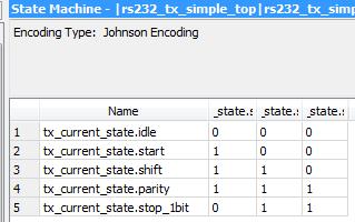
31 State Machine Coding: XST Report 31 ============================================== * Advanced HDL Synthesis * ============================================== Analyzing FSM <FSM_0> for best encoding. Optimizing FSM <rs232_tx/tx_current_state/fsm> on signal <tx_current_state[1:3]> with sequential encoding State Encoding idle 000 start 001 shift 010 parity 011 stop_1bit

32 State Machine Coding: Quartus Report 32

33 State Machine Coding: Simulation 33
34 FSM Style Description Example
35 State Machine VHDL Coding Styles 35 Inputs Next State Logic Next State Logic Next State Current Current State Logic Logic Current State Output Logic Output Logic Outputs CLK RST Coding Style Current State Next State Logic Output Logic Style E Seq. Logic Comb. Logic Seq. Logic Style A Seq. Logic Comb. Logic Comb. Logic Style C Seq. Logic Comb. Logic Style D Seq. Logic Comb. Logic Style B Seq. Logic
36 FSM: Clocked Process for Current State 36 The current_state clocked process decides when the state machine should change state This process is activated by the state machine s clock signal Depending on the current state and the value of the input signals, the state machine can change state at every active clock edge Current state gets the value of the next state on the active edge of the clock The next state value is generated in the next state process (combinational process), depending on the values of current state and the inputs
37 FSM: Combinational Process 37 Next State and Output Logic Assigns the output signals their value depending on the current state Assigns the next state value depending on the current state and the input s value(s) Next state logic and output logic is best modeled using case statements are better for this process All the rules of combinatorial process have to be followed to avoid generating unwanted latches For Mealy Machines if-then-else statement is used to create the dependency between the current state, the input signals and output signals
38 State Machine: Reset behavior 38 Asynchronous reset: ensure that the state machine is always initialized to a known valid state, before the first active clock transition and normal operation commences No reset : there is no way to predict the initial value of the state register flip-flops. It could power up and become permanently stuck in an uncoded state.
39 FSM Style Descriptions - Example 39 Moore FSM X = 0 X = 0 S0 S1 Z = 0 Z = 1 X = 1 X = 1 Mealy FSM X = 0 Z = 1 X = 0 Z = 0 S0 S1 X = 1 Z = 1 X = 1 Z = 0
 begin case state is when S0 => if(x= 0 ) then next_state <= S0; else(x= 1 ) then next_state <= S1;")
 then next_state process (clk, <= rst) S0; else(x= 1 ) then begin next_state <= S1; if(rst = 1 ) then")

40 Style E - Moore State Machine 40 Comb. Next State Logic X process (state, X) begin case state is when S0 => if(x= 0 ) then next_state <= S0; else(x= 1 ) then next_state <= S1; when S1 => if. next_state <=.. ;. when others =>. end case; end process; process (state, X) begin case state is when S0 Seq. => Present State Logic if(x= 0 ) then next_state process (clk, <= rst) S0; else(x= 1 ) then begin next_state <= S1; if(rst = 1 ) then state <= S0; when S1 => elsif (rising_edge(clk)) then if. state <= next_state; next_state <=.. ;. end process; when others =>. end case; end process; state Seq. Output Logic process (clk, rst) begin if(rst = 1 ) then Z <= 0 ; elsif (rising_edge(clk)) then case state is when S0 => Z <= 0 ; when S1 => Z <= 1 ; when others => Z <= 1 ; end case; end process; Z Clk Rst Current State Logic Output Logic
41 Style E - Moore State Machine 41 X Comb. Next State Logic process (state, X) begin case state is when S0 => if(x= 0 ) then next_state <= S0; else(x= 1 ) then next_state <= S1; when S1 => if. next_state <=.. ;. when others =>. end case; end process; Seq. Present State Logic process (clk, rst) begin if(rst = 1 ) then state <= S0; elsif (rising_edge(clk)) then state <= next_state; end process; state Seq. Output Logic process (clk, rst) begin if(rst = 1 ) then Z <= 0 ; elsif (rising_edge(clk)) then case state is when S0 => Z <= 0 ; when S1 => Z <= 1 ; when others => Z <= 1 ; end case; end process; Z Clk Rst
42 Style E - Moore State Machine VHDL code example for an FSM library ieee; use ieee.std_logic_1164.all; entity my_fsm is port( x: in std_logic; clk: in std_logic; rst: in std_logic; z: out std_logic ); end entity my fsm; architecture beh of my_fsm is -- fsm enumerated type declaration type fsm_states is (S0, S1); -- fsm signal declarations signal next_state, state: fsm_states; begin -- current state logic cst_pr: process (clk, rst) begin if(rst = 1 ) then state <= S0; elsif (rising_edge(clk)) then state <= next_state; end process cst_pr; -- next state logic nxt_pr:process (state, X) begin case state is when S0 => if(x= 0 ) then next_state <= S0; else(x= 1 ) then next_state <= S1; when S1 => if. next_state <=.. ;. when others =>. end case; end process nxt_pr; - - output logic out_pr:process (clk, rst) begin if(rst = 1 ) then Z <= 0 ; elsif (rising_edge(clk)) then case state is when S0 => Z <= 0 ; when S1 => Z <= 1 ; when others => Z<= 1 ; end case; end process out_pr; end architecture beh;
43 Style E - Mealy State Machine 43 Comb.Next State Logic X Clk Rst process (state, X) begin case state is when S0 => if(x= 0 ) then next_state <= S0; else(x= 1 ) then next_state <= S1; when S1 => if. next_state <=.. ;. when others =>. end case; end process; Warning on Mealy Outputs! Seq.Present State Logic process (clk, rst) begin if(rst = 1 ) then state <= S0; elsif (rising_edge(clk)) then state <= next_state; end process; state Seq. Output Logic process (clk, rst) begin if(rst = 1 ) then Z <= 0 ; elsif (rising_edge(clk)) then case state is when S0 => if (X = 0 ) then Z <= ; else Z <=... ; when S1 => if (X = 1 ) then... ; else... ; when others => Z<= 0 ; end case; end process; Z
44 Style A - Moore State Machine 44 Comb. Next State Logic X process (state, X) begin case state is when S0 => if(x= 0 ) then next_state <= S0; else(x= 1 ) then next_state <= S1; when S1 => if. next_state <=.. ;. when others =>. end case; end process; Seq. Present State Logic process (clk, rst) begin if(rst = 1 ) then state <= S0; elsif (rising_edge(clk)) then state <= next_state; end process; state Comb.Output Logic process (state) begin Z <= 0 ; -- default value case state is when S0 => Z <= 0 ; when S1 => Z <= 1 ; when others => Z <= 0 ; end case; end process; Z Clock Reset
45 Style A Moore Synthesis 45
46 Style A - Mealy State Machine 46 Comb. Next State Logic X Clock process (state, X) begin case state is when S0 => if(x= 0 ) then next_state <= S0; else(x= 1 ) then next_state <= S1; when S1 => if. next_state <=.. ;. when others =>. end case; end process; Seq. Present State Logic process (clk, rst) begin if(rst = 1 ) then state <= S0; elsif (rising_edge(clk)) then state <= next_state; end process; Comb. Output Logic process (state, X) begin case state is when S0 => if (X = 0 ) then Z <= ; else Z <=... ; when S1 => if (X = 1 ) then... ; else... ; when others => Z<= 0 ; end case; end process; Z Reset
47 Style A Mealy Synthesis 47 Mealy
 begin case state is when S0 => if(x= 0 ) then next_state <= S0; else(x= 1 ) then next_state <= S1; when S1 => if. next_state <=.. ;. when others =>.")
48 Style A Moore & Mealy State Machine 48 Comb. Next State Logic Comb.Output Logic Moore X Clock Reset process (state, X) begin case state is when S0 => if(x= 0 ) then next_state <= S0; else(x= 1 ) then next_state <= S1; when S1 => if. next_state <=.. ;. when others =>. end case; end process; Hypothetical case Seq. Present State Logic process (clk, rst) begin if(rst = 1 ) then state <= S0; elsif (rising_edge(clk)) then state <= next_state; end process; process (state) begin case state is when S0 => Y <= 1 ; when S1 => Y <= 0 ; when others => Y <= 0 ; end case; end process; Comb. Output Logic - Mealy process (state, X) begin case state is when S0 => if (X = 0 ) then Z <= ;... when S1 => if (X = 1 ) then... ; when others => Z<= 0 ; end case; end process; Y Z
49 Style B - Moore State Machine 49 Seq. State, Next State and Output Logic X process(clk, rst) begin if(rst = 1 ) then state <= S0; Z <= 0 ; elsif (rising_edge(clk)) then case state is when S0 => if (X= 0 ) then state <= S0; elsif (X= 1 ) then state <= S1; Z <= 0 ; when S1 => if (X = 0 ) then... Z <= 1 ; end case; end process; Z Clk Rst
50 Style B - Mealy State Machine 50 Seq. State, Next State and Output Logic X process(clk, rst) begin if(rst = 1 ) then state <= S0; Z <= 0 ; elsif (rising_edge(clk)) then case state is when S0 => if (X= 0 ) then state <=... ; Z <=... ; elsif (X= 1 ) then state <=... ; Z <=... ; when S1 => if (X = 0 ) then... end case; end process; Z Reset Clock
51 Style B Moore Synthesis 51
52 Style B Mealy Synthesis 52
53 Style C - Moore State Machine 53 Seq. Present State and Next State Logic X process (clk, rst) begin if(rst = 1 ) then State <= S0; elsif (rising_edge(clk)) then case state is when S0 => if(x = 1 ) then state <=S1; when S1 => if( X = 1 ) then state <=S0; end case; end process; Comb. Output Logic process (state) begin case state is when S0 => Z <= 0 ; when S1 => Z <= 1 ; when others Z <= 0 end case; end process; Z Clk Rst
54 Style C - Mealy State Machine 54 Seq. Present State and Next State Logic Comb. Output Logic X process (clk, rst) begin if(rst = 1 ) then State <= S0; elsif (rising_edge(clk)) then case state is when S0 => if(x = 1 ) then state <=S1; when S1 => if( X = 1 ) then state <=S0; end case; end process; process (state, X) begin case state is when S0 => if(x= 1 ) then Z <=... ; else Z <=... ; when S1 => if(x= 1 ) then Z <=... ; else Z <=... ; end case; end process; Z Clk Rst
55 Style C Moore State Machine 55
56 Style C - Mealy State Machine 56
57 Style D - Moore State Machine 57 Comb. Next State and Output Logic X process (state, X) begin next_state <= state; case state is when S0 => if(x = 1 ) then next_state <=S1; Z <= 0 ; when S1 => if( X = 1 ) then next_state <=S0; Z <= 1 ; end case; end process; Seq. Present State Logic process (clk, rst) begin if(rst = 1 ) then state <= S0; elsif (rising_edge(clk)) then state <= next_state; end process; Z Clk Rst
58 Style D - Mealy State Machine 58 Comb. Next State and Output Logic X process (state, X) begin next_state <= state; Z <=... ; case state is when S0 => if(x = 1 ) then next_state <=... ; Z <=... ; when S1 => if( X = 1 ) then next_state <=... ; Z <=... ; end case; end process; Seq. Present State Logic process (clk, rst) begin if(rst = 1 ) then state <= S0; elsif (rising_edge(clk)) then state <= next_state; end process; Z Clk Rst
59 Style D Moore State Machine 59
60 Style D - Mealy State Machine 60
61 FSM Example
62 Another Example: Memory Controller FSM 62 Let s try to obtain an state diagram of a hypothetical memory controller FSM that has the following specifications: The controller is between a processor and a memory chip, interpreting commands from the processor and then generating a control sequence accordingly. The commands, mem, rw and burst, from the processor constitute the input signals of the FSM. The mem signal is asserted to high when a memory access is required. The rdwr signal indicates the type of memory access, and its value can be either 1 or 0, for memory read and memory write respectively. The burst signal is for a special mode of a memory read operation. If it is asserted, four consecutive read operations will be performed. The memory chip has two control signals, oe (for output enable) and we (for write enable), which need to be asserted during the memory read and memory write respectively. The two output signals of the FSM, oe and we, are connected to the memory chip s control signals. For comparison purpose, let also add an artificial Mealy output signal, we_mealy, to the state diagram. Initially, the FSM is in the idle state, waiting for the mem command from the processor. Once mem is asserted, the FSM examines the value of rdwr and moves to either the read1 or the write state. The input conditions can be formalized to logic expressions, as shown below: mem : represents that no memory operation is required (mem= 0 ) mem.rdwr: represents that a memory read operation is required (mem=rdwr= 1 ). mem.rdwr : represents that a memory write operation is required (mem= 1 ; rdwr= 0 ) Based on an example from the RTL Hardware Design Using VHDL book, By Pong Chu
63 Memory Controller FSM 63 Address Bus Data Bus Processor mem Memory IC burst rdwr Memory Controller FSM oe we we_mealy
64 Memory Controller FSM 64 mem burst idle read1 oe mem.rdwr mem.rdwr we_mealy burst write we read2 oe read3 oe read4 oe
65 Memory Controller FSM 65 idle mem read1 rdwr oe we_mealy read2 burst write we oe read3 oe read4 oe
66 Memory Controller FSM VHDL Code 66 Entity-Architecture Declarations FSM enumeration type declaration, FSM signal declarations library ieee ; use ieee.std_logic_1164.all; entity mem_ctrl is port ( clk, reset : in std_logic; mem, rdwr, burst: in std_logic; oe, we, we_mealy: out std_logic ); end mem_ctrl ; architecture mult_seg_arch of mem_ctrl is type fsm_states_type is (idle, read1, read2, read3, read4, write); signal crrnt_state, next_state: fsm_states_type; begin
67 Memory Controller FSM VHDL Code 67 Current state process current state procesee cs_pr: process (clk, reset) begin if(reset = 1 ) then crrnt_state <= idle ; elsif(rising_edge(clk))then crrnt_state <= next_state; end process cs_pr;

68 68 Memory Controller FSM VHDL Code Next state process (1) next state logic nxp:process(crrnt_state,mem,rdwr,burst) begin case crrnt_state is when idle => if mem = 1 then if rw = 1 then next_state <= read1; else next_state <= write; else next_state <= idle; when write => next_state <= idle;
69 Memory Controller FSM VHDL Code 69 Next state process (2) when read1 => if (burst = 1 ) then next_state <= read2; else next_state <= idle; when read2 => next_state <= read3; when read3 => next_state <= read4; when read4 => next_state <= idle; when others => next_state <= idle; end case; end process nxp;
70 Memory Controller FSM VHDL Code 70 Moore outputs process Moore output logic moore_pr: process (crrnt_state) begin we <= 0 ; default value oe <= 0 ; default value case crrt_state is when idle => null; when write => we <= 1 ; when read1 => oe <= 1 ; when read2 => oe <= 1 ; when read3 => oe <= 1 ; when read4 => oe <= 1 ; when others => null; end case ; end process moore_pr;
71 Memory Controller FSM VHDL Code 71 Mealy output process Mealy output logic mly_pr: process(crrt_state,mem,rdwr) begin we_me <= 0 ; default value case state_reg is when idle => if (mem= 1 )and(rdwr = 0 )then we_me <= 1 ; when write => null; when read1 => null; when read2 => null; when read3 => null; when read4 => null; end case; end process mly_pr;
72 72 Memory Controller FSM VHDL Code Mealy output statement Mealy output logic we_me <= 1 when ((crrnt_state=idle) and (mem= 1 ) and(rdwr= 0 )) else 0 ;
73 Another Example
74 FSM Example RS Realizar la descripción en VHDL de un receptor y transmisor serie tipo RS-232. El dato recibido y el dato a transmitir debe tener el siguiente formato: 1 bit de start 8 bits de datos Paridad programable: paridad/no paridad, par/impar 1 bit de stop Frecuencia de transmisión por defecto es de 9600 Bauds, pero el código debe permitir también otras frecuencias como: 4800, 38400, Bauds.
75 FSM Example RS RS-232 Tx format
76 FSM Example RS SysClock Div. Frec. En Parity SysReset Dato(7:0) DatoSent StartTx?? FSM RS232 Tx Controller DatoSerie
77 FSM Example RTL Synthesis View 77

78 FSM Example Quartus State diagram 78

79 FSM Example: Solution 2 - RTL Viewer 79 RTL Viewer Double click
80 FSM Example: Solution 2- RTL Viewer 80 Double click

81 FSM Example: Solution 2 FSM Viewer 81
82 Synpsys FSM Viewer 82 In this case a clock enable is used.
83 FSM Example RS232 Other Approach 83 SysClock Div. Frec. En Parity 00 SysReset Dato(7:0) 01 DatoSerie DatoSent E1 E0 Reg Desplaz amiento 10 StartTx?? FSM RS232 Tx Controller Done StartStopBit Sel1, Sel0
84 Interacting State Machines
85 Interacting FSM 85 Controller FSM Transmitter FSM Ld_Tx CS1 TS1 CS2 Ld_Tx Tx_busy TS4 Tx_busy TS2 Tx_busy CS3 Tx_busy Tx_busy Ld_Tx TS3 Tx_busy
86 Interacting FSM 86 Inputs Next State Process Next State Current State Process Current State Output Process Controller FSM Processes Outputs Tx_busy Clk Rst Ld_Tx ctrl_tx.vhd Inputs Next State Process Next State Current State Process Current State Output Process Outputs Transmitter FSM Processes
87 Interacting FSM 87 Inputs cntrl_fsm.vhd Next State Process Next State Current State Process Current State Output Process Outputs Ld_Tx Clk Rst Tx_busy Inputs Next State Process Next State Current State Process Current State Output Process Outputs tx_fsm.vhd
Finite State Machines (FSM) Description in VHDL. Review and Synthesis
 Description in VHDL. Review and Synthesis") Finite State Machines (FSM) Description in VHDL Review and Synthesis FSM Review A sequential circuit that is implemented in a fixed number of possible states is called a Finite State Machine (FSM). Finite
Finite State Machines (FSM) Description in VHDL Review and Synthesis FSM Review A sequential circuit that is implemented in a fixed number of possible states is called a Finite State Machine (FSM). Finite
FSM Components. FSM Description. HDL Coding Methods. Chapter 7: HDL Coding Techniques
 FSM Components XST features: Specific inference capabilities for synchronous Finite State Machine (FSM) components. Built-in FSM encoding strategies to accommodate your optimization goals. You may also
Lecture 08 Finite State Machine Design Using VHDL
 Lecture 08 Finite State Machine Design Using VHDL 10/1/2006 ECE 358: Introduction to VHDL Lecture 8-1 Today Sequential digital logic system design state diagram/state graph 10/1/2006 ECE 358: Introduction
VHDL Modeling Behavior from Synthesis Perspective -Part B - EL 310 Erkay Savaş Sabancı University
 VHDL Modeling Behavior from Synthesis Perspective -Part B - EL 310 Erkay Savaş Sabancı University 1 The Wait Statement Syntax wait until condition; Different forms wait until(clk event and clk = 1 ); wait
ECE 4514 Digital Design II. Spring Lecture 15: FSM-based Control
 ECE 4514 Digital Design II Lecture 15: FSM-based Control A Design Lecture Overview Finite State Machines Verilog Mapping: one, two, three always blocks State Encoding User-defined or tool-defined State
Lab 3. Advanced VHDL
 Lab 3 Advanced VHDL Lab 3 Advanced VHDL This lab will demonstrate many advanced VHDL techniques and how they can be used to your advantage to create efficient VHDL code. Topics include operator balancing,
VHDL for Synthesis. Course Description. Course Duration. Goals
 VHDL for Synthesis Course Description This course provides all necessary theoretical and practical know how to write an efficient synthesizable HDL code through VHDL standard language. The course goes
Sequential Logic - Module 5
 Sequential Logic Module 5 Jim Duckworth, WPI 1 Latches and Flip-Flops Implemented by using signals in IF statements that are not completely specified Necessary latches or registers are inferred by the
FSM and Efficient Synthesizable FSM Design using Verilog
 FSM and Efficient Synthesizable FSM Design using Verilog Introduction There are many ways to code FSMs including many very poor ways to code FSMs. This lecture offers guidelines for doing efficient coding,
DIGITAL LOGIC DESIGN VHDL Coding for FPGAs Unit 6
 DIGITAL LOGIC DESIGN VHDL Coding for FPGAs Unit 6 FINITE STATE MACHINES (FSMs) Moore Machines Mealy Machines Algorithmic State Machine (ASM) charts FINITE STATE MACHINES (FSMs) Classification: Moore Machine:
State Machine Descriptions
 State Machine Descriptions Can be modelled using many different coding styles Style guidelines available for Moore or Mealy type machines Several encoding schemes for state variables used in FSM descriptions
Designing Safe Verilog State Machines with Synplify
 Designing Safe Verilog State Machines with Synplify Introduction One of the strengths of Synplify is the Finite State Machine compiler. This is a powerful feature that not only has the ability to automatically
Laboratory Finite State Machines and Serial Communication
 Laboratory 11 11. Finite State Machines and Serial Communication 11.1. Objectives Study, design, implement and test Finite State Machines Serial Communication Familiarize the students with Xilinx ISE WebPack
Laboratory Exercise 3 Davide Rossi DEI University of Bologna AA
 Laboratory Exercise 3 Davide Rossi DEI University of Bologna AA 2017-2018 Objectives Summary of finite state machines (Mealy, Moore) Description of FSMs in System Verilog Design of control blocks based
EE178 Lecture Verilog FSM Examples. Eric Crabill SJSU / Xilinx Fall 2007
 EE178 Lecture Verilog FSM Examples Eric Crabill SJSU / Xilinx Fall 2007 In Real-time Object-oriented Modeling, Bran Selic and Garth Gullekson view a state machine as: A set of input events A set of output
DIGITAL LOGIC WITH VHDL (Fall 2013) Unit 6
 Unit 6") DIGITAL LOGIC WITH VHDL (Fall 2013) Unit 6 FINITE STATE MACHINES (FSMs) Moore Machines Mealy Machines FINITE STATE MACHINES (FSMs) Classification: Moore Machine: Outputs depend only on the current state
DIGITAL LOGIC WITH VHDL (Fall 2013) Unit 6 FINITE STATE MACHINES (FSMs) Moore Machines Mealy Machines FINITE STATE MACHINES (FSMs) Classification: Moore Machine: Outputs depend only on the current state
VHDL Essentials Simulation & Synthesis
 VHDL Essentials Simulation & Synthesis Course Description This course provides all necessary theoretical and practical know-how to design programmable logic devices using VHDL standard language. The course
COVER SHEET: Total: Regrade Info: 5 (14 points) 7 (15 points) Midterm 1 Spring 2012 VERSION 1 UFID:
 7 (15 points) Midterm 1 Spring 2012 VERSION 1 UFID:") EEL 4712 Midterm 1 Spring 2012 VERSION 1 Name: UFID: IMPORTANT: Please be neat and write (or draw) carefully. If we cannot read it with a reasonable effort, it is assumed wrong. As always, the best answer
EEL 4712 Midterm 1 Spring 2012 VERSION 1 Name: UFID: IMPORTANT: Please be neat and write (or draw) carefully. If we cannot read it with a reasonable effort, it is assumed wrong. As always, the best answer
Lecture 12 VHDL Synthesis
 CPE 487: Digital System Design Spring 2018 Lecture 12 VHDL Synthesis Bryan Ackland Department of Electrical and Computer Engineering Stevens Institute of Technology Hoboken, NJ 07030 1 What is Synthesis?
Lecture 3. Behavioral Modeling Sequential Circuits. Registers Counters Finite State Machines
 Lecture 3 Behavioral Modeling Sequential Circuits Registers Counters Finite State Machines Behavioral Modeling Behavioral Modeling Behavioral descriptions use the keyword always, followed by optional event
Used to perform operations many times. See previous Parallel to Serial Example
 Loops- I Used to perform operations many times See previous Parallel to Serial Example Several advantages Coding style (easier to read) Laziness! When used correctly can generate better results at synthesis
Sequential Circuit Design: Principle
 Sequential Circuit Design: Principle Chapter 8 1 Outline 1. Overview on sequential circuits 2. Synchronous circuits 3. Danger of synthesizing async circuit 4. Inference of basic memory elements 5. Simple
ECE 551: Digital System *
 ECE 551: Digital System * Design & Synthesis Lecture Set 5 5.1: Verilog Behavioral Model for Finite State Machines (FSMs) 5.2: Verilog Simulation I/O and 2001 Standard (In Separate File) 3/4/2003 1 Explicit
3 Designing Digital Systems with Algorithmic State Machine Charts
 3 Designing with Algorithmic State Machine Charts An ASM chart is a method of describing the sequential operations of a digital system which has to implement an algorithm. An algorithm is a well defined
VHDL And Synthesis Review
 VHDL And Synthesis Review VHDL In Detail Things that we will look at: Port and Types Arithmetic Operators Design styles for Synthesis VHDL Ports Four Different Types of Ports in: signal values are read-only
Summary of FPGA & VHDL
 FYS4220/9220 Summary of FPGA & VHDL Lecture #6 Jan Kenneth Bekkeng, University of Oslo - Department of Physics 16.11.2011 Curriculum (VHDL & FPGA part) Curriculum (Syllabus) defined by: Lectures Lecture6:
EL 310 Hardware Description Languages Midterm
 EL 3 Hardware Description Languages Midterm 2 3 4 5 Total Name: ID : Notes: ) Please answer the questions in the provided space after each question. 2) Duration is minutes 3) Closed books and closed notes.
CSE 260 Introduction to Digital Logic and Computer Design. Exam 1. Your name 2/13/2014
 CSE 260 Introduction to Digital Logic and Computer Design Jonathan Turner Exam 1 Your name 2/13/2014 1. (10 points) Draw a logic diagram that implements the expression A(B+C)(C +D)(B+D ) directly (do not
קורס VHDL for High Performance. VHDL
 קורס VHDL for High Performance תיאור הקורס קורסזהמספקאתכלהידע התיאורטיוהמעשילכתיבתקודHDL. VHDL לסינתזה בעזרת שפת הסטנדרט הקורסמעמיקמאודומלמדאת הדרךהיעילהלכתיבתקודVHDL בכדילקבלאתמימושתכןהלוגי המדויק. הקורסמשלב
EECS150 - Digital Design Lecture 20 - Finite State Machines Revisited
 EECS150 - Digital Design Lecture 20 - Finite State Machines Revisited April 2, 2009 John Wawrzynek Spring 2009 EECS150 - Lec20-fsm Page 1 Finite State Machines (FSMs) FSM circuits are a type of sequential
Lecture 4: Modeling in VHDL (Continued ) EE 3610 Digital Systems
 EE 3610 Digital Systems") EE 3610: Digital Systems 1 Lecture 4: Modeling in VHDL (Continued ) Sequential Statements Use Process process (sensitivity list) variable/constant declarations Sequential Statements end process; 2 Sequential
EE 3610: Digital Systems 1 Lecture 4: Modeling in VHDL (Continued ) Sequential Statements Use Process process (sensitivity list) variable/constant declarations Sequential Statements end process; 2 Sequential
Finite State Machines
 Lab Workbook Introduction (FSM) are sequential circuit used in many digital systems to control the behavior of systems and dataflow paths. Examples of FSM include control units and sequencers. This lab
Verilog for High Performance
 Verilog for High Performance Course Description This course provides all necessary theoretical and practical know-how to write synthesizable HDL code through Verilog standard language. The course goes
Finite State Machines
 Lab Workbook Introduction (FSM) are sequential circuit used in many digital systems to control the behavior of systems and dataflow paths. Examples of FSM include control units and sequencers. This lab
In our case Dr. Johnson is setting the best practices
 VHDL Best Practices Best Practices??? Best practices are often defined by company, toolset or device In our case Dr. Johnson is setting the best practices These rules are for Class/Lab purposes. Industry
Graduate Institute of Electronics Engineering, NTU. Lecturer: Chihhao Chao Date:
 Design of Datapath Controllers and Sequential Logic Lecturer: Date: 2009.03.18 ACCESS IC LAB Sequential Circuit Model & Timing Parameters ACCESS IC LAB Combinational Logic Review Combinational logic circuits
ECEU530. Homework 4 due Wednesday Oct 25. ECE U530 Digital Hardware Synthesis. VHDL for Synthesis with Xilinx. Schedule
 EEU530 EE U530 igital Hardware Synthesis Lecture 11: Prof. Miriam Leeser mel@coe.neu.edu October 18, 2005 Sequential Logic in VHL Finite State Machines in VHL Project proposals due now HW 4 due Wednesday,
VHDL: RTL Synthesis Basics. 1 of 59
 VHDL: RTL Synthesis Basics 1 of 59 Goals To learn the basics of RTL synthesis. To be able to synthesize a digital system, given its VHDL model. To be able to relate VHDL code to its synthesized output.
Verilog Sequential Logic. Verilog for Synthesis Rev C (module 3 and 4)
") Verilog Sequential Logic Verilog for Synthesis Rev C (module 3 and 4) Jim Duckworth, WPI 1 Sequential Logic Module 3 Latches and Flip-Flops Implemented by using signals in always statements with edge-triggered
Verilog Sequential Logic Verilog for Synthesis Rev C (module 3 and 4) Jim Duckworth, WPI 1 Sequential Logic Module 3 Latches and Flip-Flops Implemented by using signals in always statements with edge-triggered
Control in Digital Systems
 CONTROL CIRCUITS Control in Digital Systems Three primary components of digital systems Datapath (does the work) Control (manager, controller) Memory (storage) B. Baas 256 Control in Digital Systems Control
8 Register, Multiplexer and
 8 Register, Multiplexer and Three-State Inference HDL Compiler can infer Registers (latches and flip flops) Multiplexers Three state gates This chapter discusses methods of inferring different types of
Luleå University of Technology Kurskod SMD152 Datum Skrivtid
 Luleå University of Technology Kurskod SMD152 Datum 2003-10-24 Skrivtid 9.00 13.00 1 Manual synthesis (10 p, 2 p each) Here you are given five different VHDL models. Your task is to draw the schematics
CMPE 415 Verilog Case-Statement Based State Machines II
 Department of Computer Science and Electrical Engineering CMPE 415 Verilog Case-Statement Based State Machines II Prof. Ryan Robucci Finite State Machine with Datapath A very common framework being described
CprE 583 Reconfigurable Computing
 Recap 4:1 Multiplexer CprE / ComS 583 Reconfigurable Computing Prof. Joseph Zambreno Department of Electrical and Computer Engineering Iowa State University Lecture #18 VHDL for Synthesis I LIBRARY ieee
ECE 551 Digital System Design and Synthesis. Instructor: Kewal K. Saluja. Midterm Exam
 Last (family) name: First (given) name: Student I.D. #: Department of Electrical and Computer Engineering University of Wisconsin - Madison ECE 551 Digital System Design and Synthesis Instructor: Kewal
ECE Digital Design Laboratory. Lecture 3 Finite State Machines!
 ECE 4401 - Digital Design Laboratory Lecture 3 Finite State Machines! 1!!!! Synchronous Sequential Circuits!!! Synchronous sequential logic circuits are realized using combinational logic and storage elements
Luleå University of Technology Kurskod SMD098 Datum Skrivtid
 Luleå University of Technology Kurskod SMD098 Datum 2001-12-17 Skrivtid 14.00 18.00 Tentamen i Beräkningstrukturer Antal uppgifter: 6 Max poäng: 35 Lärare: Jonas Thor Telefon: 2549 Tillåtna hjälpmedel:
Sequential Circuit Design: Principle
 Sequential Circuit Design: Principle Chapter 8 1 Outline 1. Overview on sequential circuits 2. Synchronous circuits 3. Danger of synthesizing asynchronous circuit 4. Inference of basic memory elements
CSE140L: Components and Design
 CSE140L: Components and Design Techniques for Digital Systems Lab Tajana Simunic Rosing Source: Vahid, Katz, Culler 1 Grade distribution: 70% Labs 35% Lab 4 30% Lab 3 20% Lab 2 15% Lab 1 30% Final exam
EITF35: Introduction to Structured VLSI Design
 EITF35: Introduction to Structured VLSI Design Part 1.2.2: VHDL-1 Liang Liu liang.liu@eit.lth.se 1 Outline VHDL Background Basic VHDL Component An example FSM Design with VHDL Simulation & TestBench 2
VHDL in 1h. Martin Schöberl
 VHDL in 1h Martin Schöberl VHDL /= C, Java, Think in hardware All constructs run concurrent Different from software programming Forget the simulation explanation VHDL is complex We use only a small subset
HDL. Hardware Description Languages extensively used for:
 HDL Hardware Description Languages extensively used for: Describing (digital) hardware (formal documentation) Simulating it Verifying it Synthesizing it (first step of modern design flow) 2 main options:
EITF35: Introduction to Structured VLSI Design
 EITF35: Introduction to Structured VLSI Design Part 2.2.2: VHDL-3 Liang Liu liang.liu@eit.lth.se 1 Outline Inference of Basic Storage Element Some Design Examples DFF with enable Counter Coding Style:
ECE 2300 Digital Logic & Computer Organization. More Finite State Machines
 ECE 2300 Digital Logic & Computer Organization Spring 2018 More Finite State Machines Lecture 9: 1 Announcements Prelab 3(B) due tomorrow Lab 4 to be released tonight You re not required to change partner(s)
Synthesis vs. Compilation Descriptions mapped to hardware Verilog design patterns for best synthesis. Spring 2007 Lec #8 -- HW Synthesis 1
 Verilog Synthesis Synthesis vs. Compilation Descriptions mapped to hardware Verilog design patterns for best synthesis Spring 2007 Lec #8 -- HW Synthesis 1 Logic Synthesis Verilog and VHDL started out
Programable Logic Devices
 Programable Logic Devices In the 1970s programmable logic circuits called programmable logic device (PLD) was introduced. They are based on a structure with an AND- OR array that makes it easy to implement
CSE140L: Components and Design Techniques for Digital Systems Lab. FSMs. Instructor: Mohsen Imani. Slides from Tajana Simunic Rosing
 CSE4L: Components and Design Techniques for Digital Systems La FSMs Instructor: Mohsen Imani Slides from Tajana Simunic Rosing Source: Vahid, Katz Flip-flops Hardware Description Languages and Sequential
Modeling of Finite State Machines. Debdeep Mukhopadhyay
 Modeling of Finite State Machines Debdeep Mukhopadhyay Definition 5 Tuple: (Q,Σ,δ,q 0,F) Q: Finite set of states Σ: Finite set of alphabets δ: Transition function QχΣ Q q 0 is the start state F is a set
In the previous lecture, we examined how to analyse a FSM using state table, state diagram and waveforms. In this lecture we will learn how to design
 1 In the previous lecture, we examined how to analyse a FSM using state table, state diagram and waveforms. In this lecture we will learn how to design a fininte state machine in order to produce the desired
In the previous lecture, we examined how to analyse a FSM using state table, state diagram and waveforms. In this lecture we will learn how to design
 In the previous lecture, we examined how to analyse a FSM using state table, state diagram and waveforms. In this lecture we will learn how to design a fininte state machine in order to produce the desired
CprE 583 Reconfigurable Computing
 Recap Moore FSM Example CprE / ComS 583 Reconfigurable Computing Moore FSM that recognizes sequence 10 0 1 0 1 S0 / 0 S1 / 0 1 S2 / 1 Prof. Joseph Zambreno Department of Electrical and Computer Engineering
Laboratory Exercise 7
 Laboratory Exercise 7 Finite State Machines This is an exercise in using finite state machines. Part I We wish to implement a finite state machine (FSM) that recognizes two specific sequences of applied
 Esempio FSM Description : library IEEE; use IEEE.std_logic_1164.all; use IEEE.std_logic_arith.all; use IEEE.std_logic_unsigned.all; entity esempiofsm is port ( clk: in STD_LOGIC; p: in STD_LOGIC; reset:
SEQUENTIAL STATEMENTS
 SEQUENTIAL STATEMENTS Sequential Statements Allow to describe the behavior of a circuit as a sequence of related events Can be used to model, simulate and synthesize: Combinational logic circuits Sequential
CS211 Digital Systems/Lab. Introduction to VHDL. Hyotaek Shim, Computer Architecture Laboratory
 CS211 Digital Systems/Lab Introduction to VHDL Hyotaek Shim, Computer Architecture Laboratory Programmable Logic Device (PLD) 2/32 An electronic component used to build reconfigurable digital circuits
VHDL. VHDL History. Why VHDL? Introduction to Structured VLSI Design. Very High Speed Integrated Circuit (VHSIC) Hardware Description Language
 Hardware Description Language") VHDL Introduction to Structured VLSI Design VHDL I Very High Speed Integrated Circuit (VHSIC) Hardware Description Language Joachim Rodrigues A Technology Independent, Standard Hardware description Language
VHDL Introduction to Structured VLSI Design VHDL I Very High Speed Integrated Circuit (VHSIC) Hardware Description Language Joachim Rodrigues A Technology Independent, Standard Hardware description Language
CSE140L: Components and Design Techniques for Digital Systems Lab
 CSE140L: Components and Design Techniques for Digital Systems Lab Tajana Simunic Rosing Source: Vahid, Katz, Culler 1 Announcements & Outline Lab 4 due; demo signup times listed on the cse140l site Check
Verilog introduction. Embedded and Ambient Systems Lab
 Verilog introduction Embedded and Ambient Systems Lab Purpose of HDL languages Modeling hardware behavior Large part of these languages can only be used for simulation, not for hardware generation (synthesis)
Reconfigurable Hardware Design (coursework)
") EEE8076 Reconfigurable Hardware Design (coursework) Dr A. Bystrov Dr. E.G. Chester Autumn 2010 Module Outline Teaching Staff Dr Alex Bystrov Dr Graeme Chester The contact details are in the EECE web page
EEE8076 Reconfigurable Hardware Design (coursework) Dr A. Bystrov Dr. E.G. Chester Autumn 2010 Module Outline Teaching Staff Dr Alex Bystrov Dr Graeme Chester The contact details are in the EECE web page
ECE 448 Lecture 4. Sequential-Circuit Building Blocks. Mixing Description Styles
 ECE 448 Lecture 4 Sequential-Circuit Building Blocks Mixing Description Styles George Mason University Reading Required P. Chu, FPGA Prototyping by VHDL Examples Chapter 4, Regular Sequential Circuit Recommended
Quick Introduction to SystemVerilog: Sequental Logic
 ! Quick Introduction to SystemVerilog: Sequental Logic Lecture L3 8-545 Advanced Digital Design ECE Department Many elements Don Thomas, 24, used with permission with credit to G. Larson Today Quick synopsis
EECS150 - Digital Design Lecture 10 Logic Synthesis
 EECS150 - Digital Design Lecture 10 Logic Synthesis February 13, 2003 John Wawrzynek Spring 2003 EECS150 Lec8-synthesis Page 1 Logic Synthesis Verilog and VHDL started out as simulation languages, but
Bulletproofing FSM Verification Automated Approach to Detect Corner Case Issues in an FSM Design
 Bulletproofing FSM Verification Automated Approach to Detect Corner Case Issues in an FSM Design Lisa Piper Technical Marketing Real Intent Inc., Sunnyvale, CA Comprehensive verification of Finite State
Midterm Exam Thursday, October 24, :00--2:15PM (75 minutes)
") Last (family) name: Answer Key First (given) name: Student I.D. #: Department of Electrical and Computer Engineering University of Wisconsin - Madison ECE 551 Digital System Design and Synthesis Midterm
Last (family) name: Answer Key First (given) name: Student I.D. #: Department of Electrical and Computer Engineering University of Wisconsin - Madison ECE 551 Digital System Design and Synthesis Midterm
Note: Closed book no notes or other material allowed, no calculators or other electronic devices.
 ECE 574: Modeling and Synthesis of Digital Systems using Verilog and VHDL Fall 2017 Exam Review Note: Closed book no notes or other material allowed, no calculators or other electronic devices. One page
ECE 545 Lecture 12. Datapath vs. Controller. Structure of a Typical Digital System Data Inputs. Required reading. Design of Controllers
 ECE 545 Lecture 12 Design of Controllers Finite State Machines and Algorithmic State Machine (ASM) Charts Required reading P. Chu, using VHDL Chapter 1, Finite State Machine: Principle & Practice Chapter
FPGA for Software Engineers
 FPGA for Software Engineers Course Description This course closes the gap between hardware and software engineers by providing the software engineer all the necessary FPGA concepts and terms. The course
The University of Alabama in Huntsville ECE Department CPE Midterm Exam Solution Spring 2016
 The University of Alabama in Huntsville ECE Department CPE 526 01 Midterm Exam Solution Spring 2016 1. (15 points) Write a VHDL function that accepts a std_logic_vector of arbitrary length and an integer
VHDL for Logic Synthesis
 VHDL for Logic Synthesis Overview Design Flow for Hardware Design VHDL coding for synthesis General guidelines for hardware designers This lecture includes the content from: Nitin Yogi, Modelling for Synthesis
CMPE 415 Verilog Case-Statement Based State Machines II
 Department of Computer Science and Electrical Engineering CMPE 415 Verilog Case-Statement Based State Machines II Prof. Ryan Robucci Finite State Machine (FSM) Characterized by A set of states A set of
Logic Synthesis. EECS150 - Digital Design Lecture 6 - Synthesis
 Logic Synthesis Verilog and VHDL started out as simulation languages, but quickly people wrote programs to automatically convert Verilog code into low-level circuit descriptions (netlists). EECS150 - Digital
[VARIABLE declaration] BEGIN. sequential statements
![[VARIABLE declaration] BEGIN. sequential statements](/thumbs/89/98890993.jpg "[VARIABLE declaration] BEGIN. sequential statements") PROCESS statement (contains sequential statements) Simple signal assignment statement
PROCESS statement (contains sequential statements) Simple signal assignment statement
1 ST SUMMER SCHOOL: VHDL BOOTCAMP PISA, JULY 2013
 MARIE CURIE IAPP: FAST TRACKER FOR HADRON COLLIDER EXPERIMENTS 1 ST SUMMER SCHOOL: VHDL BOOTCAMP PISA, JULY 2013 Introduction to VHDL Calliope-Louisa Sotiropoulou PhD Candidate/Researcher Aristotle University
EEL 4783: HDL in Digital System Design
 EEL 4783: HDL in Digital System Design Lecture 15: Logic Synthesis with Verilog Prof. Mingjie Lin 1 Verilog Synthesis Synthesis vs. Compilation Descriptions mapped to hardware Verilog design patterns for
Sequential Statement
 Sequential Statement Sequential Logic Output depends not only on current input values but also on previous input values. Are building blocks of; Counters Shift registers Memories Flip flops are basic sequential
DESCRIPTION OF DIGITAL CIRCUITS USING VHDL
 DESCRIPTION OF DIGITAL CIRCUITS USING VHDL Combinatinal circuits Sequential circuits Design organization. Generic design Iterative operations Authors: Luis Entrena Arrontes, Celia López, Mario García,
Verilog Tutorial. Introduction. T. A.: Hsueh-Yi Lin. 2008/3/12 VLSI Digital Signal Processing 2
 Verilog Tutorial T. A.: Hsueh-Yi Lin Introduction 2008/3/12 VLSI Digital Signal Processing 2 Verilog: A common language for industry HDL is a common way for hardware design Verilog VHDL Verilog is widely
Nanosistemų programavimo kalbos 5 paskaita. Sekvencinių schemų projektavimas
 Nanosistemų programavimo kalbos 5 paskaita Sekvencinių schemų projektavimas Terminai Combinational circuit kombinacinė schema (be atminties elementų) Sequential circuit nuosekli (trigerinė, sekvencinė)
ECE 2300 Digital Logic & Computer Organization. More Verilog Finite State Machines
 ECE 2300 Digital Logic & Computer Organization Spring 2018 More Verilog Finite Machines Lecture 8: 1 Prelim 1, Thursday 3/1, 1:25pm, 75 mins Arrive early by 1:20pm Review sessions Announcements Monday
EECS150 - Digital Design Lecture 10 Logic Synthesis
 EECS150 - Digital Design Lecture 10 Logic Synthesis September 26, 2002 John Wawrzynek Fall 2002 EECS150 Lec10-synthesis Page 1 Logic Synthesis Verilog and VHDL stated out as simulation languages, but quickly
Latch Based Design (1A) Young Won Lim 2/18/15
 Young Won Lim 2/18/15") Latch Based Design (1A) Copyright (c) 2015 Young W. Lim. Permission is granted to copy, distribute and/or modify this document under the terms of the GNU Free Documentation License, Version 1.2 or any
Latch Based Design (1A) Copyright (c) 2015 Young W. Lim. Permission is granted to copy, distribute and/or modify this document under the terms of the GNU Free Documentation License, Version 1.2 or any
: : (91-44) (Office) (91-44) (Residence)
 (Office) (91-44) (Residence)") Course: VLSI Circuits (Video Course) Faculty Coordinator(s) : Prof. S. Srinivasan Department of Electrical Engineering Indian Institute of Technology Madras Chennai 600036 Email Telephone : srinis@iitm.ac.in,
Course: VLSI Circuits (Video Course) Faculty Coordinator(s) : Prof. S. Srinivasan Department of Electrical Engineering Indian Institute of Technology Madras Chennai 600036 Email Telephone : srinis@iitm.ac.in,
Synthesis from VHDL. Krzysztof Kuchcinski Department of Computer Science Lund Institute of Technology Sweden
 Synthesis from VHDL Krzysztof Kuchcinski Krzysztof.Kuchcinski@cs.lth.se Department of Computer Science Lund Institute of Technology Sweden March 23, 2006 Kris Kuchcinski (LTH) Synthesis from VHDL March
Two HDLs used today VHDL. Why VHDL? Introduction to Structured VLSI Design
 Two HDLs used today Introduction to Structured VLSI Design VHDL I VHDL and Verilog Syntax and ``appearance'' of the two languages are very different Capabilities and scopes are quite similar Both are industrial
Part 4: VHDL for sequential circuits. Introduction to Modeling and Verification of Digital Systems. Memory elements. Sequential circuits
 M1 Informatique / MOSIG Introduction to Modeling and erification of Digital Systems Part 4: HDL for sequential circuits Laurence PIERRE http://users-tima.imag.fr/amfors/lpierre/m1arc 2017/2018 81 Sequential
EECS150 - Digital Design Lecture 5 - Verilog Logic Synthesis
 EECS150 - Digital Design Lecture 5 - Verilog Logic Synthesis Jan 31, 2012 John Wawrzynek Spring 2012 EECS150 - Lec05-verilog_synth Page 1 Outline Quick review of essentials of state elements Finite State
Outline. Finite State Machine. 2. Representation of FSM. 1. Overview on FSM
 Finite State Machine Outline 1. Overview 2. FSM representation 3. Timing and performance of an FSM 4. Moore machine versus Mealy machine 5. VHDL description of FSMs 6. State assignment 7. Moore output
Sign here to give permission to return your test in class, where other students might see your score:
 EEL 4712 Midterm 1 Spring 2017 VERSION 1 Name: UFID: Sign here to give permission to return your test in class, where other students might see your score: IMPORTANT: Please be neat and write (or draw)
Mealy and Moore examples
 CSE 37 Spring 26 Introduction to igital esign ecture 2: uential ogic Technologies ast ecture Moore and Mealy Machines Today uential logic technologies Ving machine: Moore to synch. Mealy OPEN = creates
Lecture 7. Standard ICs FPGA (Field Programmable Gate Array) VHDL (Very-high-speed integrated circuits. Hardware Description Language)
 VHDL (Very-high-speed integrated circuits. Hardware Description Language)") Standard ICs FPGA (Field Programmable Gate Array) VHDL (Very-high-speed integrated circuits Hardware Description Language) 1 Standard ICs PLD: Programmable Logic Device CPLD: Complex PLD FPGA: Field Programmable
Standard ICs FPGA (Field Programmable Gate Array) VHDL (Very-high-speed integrated circuits Hardware Description Language) 1 Standard ICs PLD: Programmable Logic Device CPLD: Complex PLD FPGA: Field Programmable