Chip8 Emulator. Columbia University. Embedded Systems CSEE Final Report. Supervisor: Stephen A. Edwards
|
|
|
- Chrystal Lamb
- 6 years ago
- Views:
Transcription


1 Columbia University Embedded Systems CSEE 8 Final Report Chip8 Emulator Authors: Ashley Kling Levi Oliver Gabrielle Taylor David Watkins Supervisor: Stephen A. Edwards May, 6
2 Contents Introduction System Overview 6. Memory Overview Graphics Hardware Software Interface Op Codes nnn - SYS addr E - CLS EE - RET nnn - JP addr nnn - CALL addr xkk - SE Vx, byte xkk - SNE Vx, byte xy - SE Vx, Vy xkk - LD Vx, byte xkk - ADD Vx, byte xy - LD Vx, Vy xy - OR Vx, Vy xy - AND Vx, Vy xy - XOR Vx, Vy xy - ADD Vx, Vy xy - SUB Vx, Vy xy6 - SHR Vx {, Vy} xy7 - SUBN Vx, Vy xyE - SHL Vx {, Vy} xy - SNE Vx, Vy Annn - LD I, addr
3 .. Bnnn - JP V, addr Cxkk - RND Vx, byte Dxyn - DRW Vx, Vy, nibble Ex9E - SKP Vx ExA - SKNP Vx Fx7 - LD Vx, DT FxA - LD Vx, K Fx - LD DT, Vx Fx8 - LD ST, Vx FxE - ADD I, Vx Fx9 - LD F, Vx Fx - LD B, Vx Fx - LD [I], Vx Fx6 - LD Vx, [I] Keyboard Input Sound Screenshots Hardware Design 8. CPU, Top and Module Access Control ALU Random Number Generator BCD Graphics and Framebuffer Memory and Registers Sound Return Address Stack and Program Counter Timers Software Overview. Chip8.c Chip8driver.c Data Transfer ISA Project Plan. Lessons Learned Timeline
4 6 Debugging 7 Code Listing 7. SystemVerilog Code bcd.sv Chip8 CPU.sv Chip8 rand num generator.sv Chip8 Stack.sv Chip8 ALU.sv Chip8 framebuffer.sv Chip8 VGA Emulator.sv audio codec.sv audio effects.sv Chip8 SoundController.sv ic av config.sv ic controller.sv clk div.sv timer.sv Chip8 Top.sv SoCKit top.sv utils.svh enums.svh Testbenches Chip8 CPU 6xkk 7xkk.sv Chip8 CPU big testbench.sv Chip8 CPU testbench.sv Chip8 Top test.sv delay timer testbench.sv Triple port reg file test.sv fb testbench.sv alu testbench.sv Linux Code chip8.c chip8driver.c chip8driver.h Makefile socfpga.dts usbkeyboard.c
5 7..7 usbkeyboard.h Git commit history Schematics Chip8 framebuffer.sv clk div.sv timer.sv Chip8 rand num generator.sv bcd.sv memory.sv Chip8 SoundController.sv Entire Design

6 Chapter Introduction Chip-8 is an interpreted programming language from the 97s. It ran on the COSMAC VIP, and supported many programs such as Pac-Man, Pong, Space Invaders, and Tetris. We aim to create a processor using SystemVerilog and the FPGA on the SoCKit board that runs these programs. During the boot process of the processor chip8 ROM files will be transferred onto the main memory of the processor. The processor will also allow for save states and restoring of states. The processor will handle keyboard inputs and output graphics and sound. Figure.: A popular Chip8 game: Pong
7 Chapter System Overview. Memory Overview The Chip-8 specification requires the use of sixteen 8-bit registers (V-VF), a 6-bit index register, a 6-byte stack with 8-bit stack pointer, an 8-bit delay timer, an 8-bit sound timer, a 6x bit frame buffer, and a 6-bit program counter. The Chip8 specification also supported 96 bytes of addressable memory. All of the supported programs will start at memory location x. The sound and delay timers sequentially decrease at a rate of per tick of a 6Hz clock. When the sound timer is above, the sound will play as a single monotone beep. The framebuffer is an (x, y) addressable memory array that designates whether a pixel is currently on or off. This will be implemented with a write address, an (x, y) position, a offset in the x direction, and an 8-bit group of pixels to be drawn to the screen. The return address stack stores previous program counters when jumping into a new routine. The VF register is frequently used for storing carry values from a subtraction or addition action, and also specifies whether a particular pixel is to be drawn on the screen. 6

8 . Graphics Figure.: Chip8 K memory layout Important to the specification is the 6x pixel display that is associated with the Chip8. Each pixel only contains the information as to whether it is on or off. All setting of pixels of this display are done through the use of sprites that are always 8 N where N is the pixel height of the sprite. Chip8 comes with a font set (sprites) that allows character -9 and A-F to be printed directly to the screen. Each one of these characters fit within a 8x grid... Hardware Software Interface To start running a program, the function loadrom and loadfontset (located in chip8.c) are called. The latter writes the fontset to the Chip8 memory, 7

9 Figure.: The screen dimensions for the VGA output while the former writes a chip8 program (like Pong!) to the chip8 memory. From the software side, loadfontset copies the pre-defined font set from linux memory to Chip8 memory by writing byte by byte to processor memory, starting from chip8 memory address. loadrom copies a chip8 program from the linux memory to the Chip8 memory byte by byte starting at chip8 memory address x, which is the standard initial address for Chip8 programs. A -bit channel exists that writes from the linux side to the hardware. This channel is broken into two parts: an 8-bit channel that is used to tell the chip what type memory to modify or read (stack, memory, registers, etc.), a bit data channel that includes whatever data is needed (writedata, write enable, and sometimes addressing), and a one-bit channel signifying if the call is a read or a write.. From the hardware side, if chipselect goes high, the processor reads data from the bus. It takes in the 8-bit channel (called address), and the - bit channel (called writedata). The stage is frozen while input is processed. The address channel tells what needs to be modified. For example, if address==x9, the processor begins to modify memory. If the write channel is high, it starts to write the data signified by bits writedata[7:] to memory addressed by writedata[8:9]. (See Chip8 Top line 8.) As soon as chipselect goes low again, we resume normal operation of the 8

10 Figure.: Chip8 character sprite specification processor, restoring all possibly changed values to what they were previously. 9

11 Figure.: Overview of the design of the emulator. Op Codes The Chip8 interpreter works by parsing 6 bit opcodes and operating on the data. All supported op codes in the original Chip8 specification are included... nnn - SYS addr Jump to a machine code routine at nnn. This instruction is only used on the old computers on which Chip-8 was originally implemented. It is ignored by modern interpreters. This will not be implemented... E - CLS Clear the display... EE - RET Return from a subroutine.the interpreter sets the program counter to the address at the top of the stack, then subtracts from the stack pointer.
12 .. nnn - JP addr Jump to location nnn. The interpreter sets the program counter to nnn... nnn - CALL addr Call subroutine at nnn. The interpreter increments the stack pointer, then puts the current PC on the top of the stack. The PC is then set to nnn...6 xkk - SE Vx, byte Skip next instruction if Vx = kk. The interpreter compares register Vx to kk, and if they are equal, increments the program counter by...7 xkk - SNE Vx, byte Skip next instruction if Vx!= kk. The interpreter compares register Vx to kk, and if they are not equal, increments the program counter by...8 xy - SE Vx, Vy Skip next instruction if Vx = Vy. The interpreter compares register Vx to register Vy, and if they are equal, increments the program counter by...9 6xkk - LD Vx, byte Set Vx = kk. The interpreter puts the value kk into register Vx... 7xkk - ADD Vx, byte Set Vx = Vx + kk. Adds the value kk to the value of register Vx, then stores the result in Vx... 8xy - LD Vx, Vy Set Vx = Vy. Stores the value of register Vy in register Vx.
13 .. 8xy - OR Vx, Vy Set Vx = Vx OR Vy. Performs a bitwise OR on the values of Vx and Vy, then stores the result in Vx. A bitwise OR compares the corresponding bits from two values, and if either bit is, then the same bit in the result is also. Otherwise, it is... 8xy - AND Vx, Vy Set Vx = Vx AND Vy. Performs a bitwise AND on the values of Vx and Vy, then stores the result in Vx. A bitwise AND compares the corresponding bits from two values, and if both bits are, then the same bit in the result is also. Otherwise, it is... 8xy - XOR Vx, Vy Set Vx = Vx XOR Vy. Performs a bitwise exclusive OR on the values of Vx and Vy, then stores the result in Vx. An exclusive OR compares the corresponding bits from two values, and if the bits are not both the same, then the corresponding bit in the result is set to. Otherwise, it is... 8xy - ADD Vx, Vy Set Vx = Vx + Vy, set VF = carry. The values of Vx and Vy are added together. If the result is greater than 8 bits (i.e.,,) VF is set to, otherwise. Only the lowest 8 bits of the result are kept, and stored in Vx...6 8xy - SUB Vx, Vy Set Vx = Vx - Vy, set VF = NOT borrow. If Vx Vy, then VF is set to, otherwise. Then Vy is subtracted from Vx, and the results stored in Vx...7 8xy6 - SHR Vx {, Vy} Set Vx = Vx SHR. If the least-significant bit of Vx is, then VF is set to, otherwise. Then Vx is divided by.
14 ..8 8xy7 - SUBN Vx, Vy Set Vx = Vy - Vx, set VF = NOT borrow. If Vy Vx, then VF is set to, otherwise. Then Vx is subtracted from Vy, and the results stored in Vx...9 8xyE - SHL Vx {, Vy} Set Vx = Vx SHL. If the most-significant bit of Vx is, then VF is set to, otherwise to. Then Vx is multiplied by... 9xy - SNE Vx, Vy Skip next instruction if Vx!= Vy. The values of Vx and Vy are compared, and if they are not equal, the program counter is increased by... Annn - LD I, addr Set I = nnn. The value of register I is set to nnn... Bnnn - JP V, addr Jump to location nnn + V. The program counter is set to nnn plus the value of V... Cxkk - RND Vx, byte Set Vx = random byte AND kk. The interpreter generates a random number from to, which is then ANDed with the value kk. The results are stored in Vx. See instruction 8xy for more information on AND... Dxyn - DRW Vx, Vy, nibble Display n-byte sprite starting at memory location I at (Vx, Vy), set VF = collision. The interpreter reads n bytes from memory, starting at the address stored in I. These bytes are then displayed as sprites on screen at coordinates (Vx, Vy). Sprites are XOR d onto the existing screen. If this causes any pixels to be erased, VF is set to, otherwise it is set to. If the sprite is positioned so part of it is outside the coordinates of the display, it wraps around to the opposite side of the screen.
15 .. Ex9E - SKP Vx Skip next instruction if key with the value of Vx is pressed. Checks the keyboard, and if the key corresponding to the value of Vx is currently in the down position, PC is increased by...6 ExA - SKNP Vx Skip next instruction if key with the value of Vx is not pressed. Checks the keyboard, and if the key corresponding to the value of Vx is currently in the up position, PC is increased by...7 Fx7 - LD Vx, DT Set Vx = delay timer value. The value of DT is placed into Vx...8 FxA - LD Vx, K Wait for a key press, store the value of the key in Vx. All execution stops until a key is pressed, then the value of that key is stored in Vx...9 Fx - LD DT, Vx Set delay timer = Vx. Delay Timer is set equal to the value of Vx... Fx8 - LD ST, Vx Set sound timer = Vx. Sound Timer is set equal to the value of Vx... FxE - ADD I, Vx Set I = I + Vx. The values of I and Vx are added, and the results are stored in I... Fx9 - LD F, Vx Set I = location of sprite for digit Vx. The value of I is set to the location for the hexadecimal sprite corresponding to the value of Vx. See section.,

16 Display, for more information on the Chip-8 hexadecimal font. To obtain this value, multiply VX by (all font data stored in first 8 bytes of memory)... Fx - LD B, Vx Store BCD representation of Vx in memory locations I, I+, and I+. The interpreter takes the decimal value of Vx, and places the hundreds digit in memory at location in I, the tens digit at location I+, and the ones digit at location I+... Fx - LD [I], Vx Stores V to VX in memory starting at address I. I is then set to I + x +... Fx6 - LD Vx, [I] Fills V to VX with values from memory starting at address I. I is then set to I + x +.. Keyboard Input The keyboard input was a 6-key keyboard with keys 9, A F. There are a series of op codes (listed in the previous section) that use these key presses. In the design associated with this emulator, the keyboard input will be read in from the ARM processor running Linux and streamed to the emulator. Figure.: Chip8 6-key keyboard specification For this project we also added keyboard input for pausing, starting, and resetting the device. The P key is mapped to pause, the O key is mapped to reset, and the Enter key is mapped to run.
17 . Sound Chip-8 provides timers, a delay timer and a sound timer. The delay timer is active whenever the delay timer register (DT) is non-zero. This timer does nothing more than subtract from the value of DT at a rate of 6Hz. When DT reaches, it deactivates. The sound timer is active whenever the sound timer register (ST) is non-zero. This timer also decrements at a rate of 6Hz, however, as long as ST s value is greater than zero, the Chip-8 buzzer will sound. When ST reaches zero, the sound timer deactivates. The output of the sound generator has one tone. In the following implementation it will have a soft tone so as to not aggravate the user..6 Screenshots Figure.6: Tapeworm game running on the device 6

18 Figure.7: Chip8 logo ROM running on the device Figure.8: Brick game running on the device 7

19 Chapter Hardware Design Figure.: Overview of the hardware design. CPU, Top and Module Access Control Chip8 Top.sv handles input from the linux side and its effects on the hardware. The linux side reads from and writes to the hardware on startup and requires access to the register file, as well as the memory. The CPU also 8
20 requires access to memory and the register file. To deal with the multiple pieces requiring access to multiple modules, Chip8 Top.sv handles arbitration, deciding what gets access to what and when. It controls access to the framebuffer, memory, register file, sound controller, delay timers, and the stack. Access to all of these are required by both the C code, as well as the CPU, so all requests are put through Chip8 Top. Chip8 Top is mostly a large arbitration unit, but it also has some functionality. It contains the I-register (see section Memory and Register File), which is important in branching, jumping, and draw-sprite instructions. It also manages the program counter and instruction loading. It is important to note that instructions are 6 bits each, so each time the program counter increments by a single instruction, the value of the program counter increments at. Since Chip8 programs start at address x, the program counter starts at this value. The CPU (Chip8 CPU.sv) is completely combinational. It has no latches and is contained in a very large always comb block. However, it does not execute any instructions in a single MHz clock cycle. We cut the effective cycle time of the chip down from MHz down to khz, as is appropriate for real Chip8 systems. We made a variable in Chip8 Top.sv called stage. stage increments to a value of, before it resets to zero. When stage is or, the processor is loading the next instruction to execute from memory. When stage is greater, the processor is executing the instruction. The instruction that is using the most stages is instruction xe clear screen, which keeps working until stage is 889 (which is approximately 8 ). While this large value of stage is not necessary, it uses a minimal amount of logic for this instruction. During most values of stage, nothing is actually happening other than waiting. As stated previously, the CPU is completely combinational. Many instructions are broken apart into a few steps. For example, x7xkk first has a -cycle period of waiting for data to come in, and then a one-cycle period of writing the correct output. When an instruction is loaded and being executed, Chip8 CPU.sv sets all pins to the correct values and Chip8 Top.sv connects those pins to the appropriate destinations. For example, say we are in stage,. No instructions run during this period. Say the program counter is equal to xc. The next instruction is in memory at address xc, and that instruction is equal to x6e. At stage,, the program counter is set equal to xc. Then, stage is reset to. During stages and, the instruction is set equal to the values in memory 9
21 at xc and xc. In this case, that instruction is x6e. This is the x6xkk instruction, which sets Vx = kk. See the section on opcodes to read more about what this instruction does. During stages and, the CPU will set reg addr to x, and reg writedata to xe. It will also set reg WE high to enable writing. These values will be picked up by Chip8 Top and directed to the register file to assign the value xe to register V. Chip8 CPU has direct access to the random number generator, the binarycoded-decimal converter, and the ALU, all of which take in and output values combinationally.. ALU In order to reduce the number of operations that the CPU used, we implemented an ALU that has functions for addition, subtraction, AND, OR, XOR, left shift by, and right shift by. The ALU takes in two 6 bit inputs, and results are truncated when needed by the CPU.. Random Number Generator The random number generator is a 6 bit random number output that starts with an initial value and does a naive xor loop over the 6 bit number on each clock cycle. This is critical for the CXKK instruction which requires a random number anded with the KK byte.. BCD The binary to BCD conversion was was implemented combinatorially using a sequence of bit shifts to extract the ones, tens and hundreds place from an 8 bit binary number. The algorithm works by shifting the binary encoding of the number to the left and then determining as each bit is shifted if the value is too large for a BCD digit (between and 9). This occurs because with each successive left shift, the original binary value is doubled. This is mitigated by checking the value of each BCD digit before shifting. If the value of a BCD digit is greater than, then is added to carry the value over into the next digit.
22 . Graphics and Framebuffer The screen of the original Chip8 system was 6x (which is 8 pixels). It uses sprite-based drawing, but in a slightly strange way it draws images by XORing the value of what is to be drawn with the value of the existing display. This is interesting and useful if a sprite is to be erased, one would simply draw the sprite again in the exact location. However, this rapid drawing and erasing leads to rapidly blinking displays. To actually display the screen, we adapted Professor Edwards s VGA LED Emulator code. The screen displayed is centered in the VGA monitor, with each bit of framebuffer memory representing an eight-by-eight square of pixels (see figure below). Our adaptation of the VGA LED Emulator uses simple arithmetic and bit shifting to make sure that each VGA coordinate is properly translated to the correct location in framebuffer memory. Figure.: Double buffering diagram for the framebuffer To reduce the amount of blinking, we implemented a double-buffered framebuffer. We used the pre-built Quartus MegaFunction Wizard to create a 8-bit dual-ported memory file with bit-level granularity, which we used twice. Using the Wizard greatly reduced compile time. The first of these was written to by the CPU whenever the draw command was called. There was only a single opcode that ever wrote to the framebuffer: opcode xdxyn (see section on opcodes for more details). The other memory file was connected to the display, which was constantly requesting data to draw. The buffer attached to the VGA Emulator would only have data copied into it, cycles ( milliseconds at our MHz clock frequency) after a draw command was given. However, this could give rise to more problems. Oftentimes, programs have looping draw commands. If draw commands happen more than once every, cycles, data would never be copied over. To combat this, we added an override: if the time since the last draw ever exceeded, cycles (ms), we would force the data to copy over. The draw sprite instruction (xdxyn) specifies the coordinates that the sprites are supposed to be drawn at in (x-coord, y-coord) format. Because this was the only type of addressing the CPU would do, the framebuffer takes in an x and
23 y coordinate, and writes to the corresponding location in memory. In the actual memory, bits to 6 represent the first row, 6 to 7 represent the second row, 8 to 9 represent the third row, and so on. The memory file generated by the Wizard does not have combinational reads all data coming from a read command comes at the rising edge of the next clock cycle. Because of this, when copying data from the CPU-side memory to the screen-side memory, every address requested by the screenside memory had to be offset by one. We requested data from address to 7, but every address that data was requested from was always one more than the address being written to. This completely copies the entire memory, including all edges and corners. Relevant code: Chip8 VGA Emulator.sv, Chip8 Framebuffer.sv, Framebuffer.v, enums.svh.6 Memory and Registers The original Chip8 system used 96 (xfff) bytes of memory. Addresses to (xff) were reserved for the interpreter. The first 8 bytes of memory were generally reserved for the fontset (one -byte character for each hexadecimal character -F) for the display. Address (x) was the start of most Chip8 programs. From there, all the way up to the end of memory, the program could use as much space as needed. The register file was composed of 6 -byte registers. They are called V through VF. V through VE are used for general purpose computing, while VF is generally reserved for flags. For example, VF is set to if a certain add instruction (opcode x8xy) overflows past a single byte, and if not. VF is also used to tell if the draw instruction (xdxyn) has erased any bits. The Chip8 memory file is very large. We decided to use the MegaFunction Wizard to create our memory file. While it is not the most adaptable, it was much faster than using inferred memory. It is dual-ported. While no instructions actually involve reading from or writing to more than one memory address, we still decided to use a dual-ported memory. This left us with a channel open to send data to the linux side. Since instructions are 6 bits, and each entry is 8 bits, this also allowed us to request both bytes of an instruction in a single cycle. Because many instructions require reading from two registers at the same time, we used a dual-ported memory for the register file. This allowed us to
24 get both values simultaneously, as well as write back to the register file (for example, instructions like x8xy: Vx = Vx + Vy). One very important fact to note regarding these memory modules is that they do not have combinational reads. When an address is set, the output only reflects this change an entire cycle afterwards. Chip8 also uses a special 6-bit register called the I-register. This register was simply declared as a logic[:] variable in Chip8 Top.sv..7 Sound Sound was implemented writing an audio codec that implements the Inter- Integrated Circuit (I C) Protocol. The I C controller and I C configuration modules were implemented in order to correctly interface with the audio hardware on the FPGA. An audio codec contained the necessary clocks used to drive the output, in particular a phase locked loop (PLL) generated using the Quartus Megawizard for the Master clock, which had to operate at a frequency of.896 MHz and was not easily or accurately approximated using a clock divider. The samples for the Hz sine wave were stored in memory on the chip. Since the only sound required is a single beep, this was sufficient. The top level module assigned the remaining signals..8 Return Address Stack and Program Counter The program counter is kept as a register (a register not a reg datatype) in Chip8 Top.sv. We calculate what the next program counter should be in stage. (See NEXT PC WRITE STAGE in enums.svh.) This is a somewhat arbitrary value. The stage needed to be late enough so that the processor would have enough time to calculate what the next instruction should be. Whenever the stage reaches, we calculate what the next PC should be. By default, next pc is set to pc+. Since the memory granularity is a single byte, and instructions are two bytes each, pointing the program counter to the next instruction involves incrementing the program counter by. However, most programs involve branches, jumps, and subroutine calls. For that, we have an enum declared in enums.svh. Depending on the instruction, the CPU sets a flag, pc src, to different values. Chip8 Top interprets them as follows: if pc src == PC SRC ALU, next pc is set to the value that the
25 CPU is writing to it if pc src == PRC SRC SKIP, next pc is set to pc+. This effectively skips the next instruction if pc src == PC SRC NEXT, next pc is set to pc+. This is the default, which increments the PC by one instruction. There is also a special case for setting next pc. The CPU sets flags regarding the return address stack (RAS). This flag, stk op, acts as follows: if the CPU sets stk op to STACK HOLD, the PC is unaffected by the RAS if the CPU sets stk op to STACK PUSH, pc+ is pushed to the top of the stack if the CPU sets stk op to STACK POP, next pc is set to the value on top of the RAS in in stage, and the top of the RAS is popped off. The stack pointer decreases by. The RAS has 6 entries of 6 bits each. The stack does not push every cycle that stk op == STACK PUSH, nor does it pop every time it equals STACK POP. These operations only happen when stk op changes from STACK HOLD to either of these operations.9 Timers There are two timers used in Chip8. These are the delay timer and sound timer. Both timers function the same way, that is, they are set to a particular value and count down at a rate of about 6 Hz per second. In order to implement this, a simple clock divider was implemented as a separate unit, which was then fed into the delay timer. The clock divider simply counts the relevant number of MHz CPU cycles to equal one 6 Hz cycle, then is high for a single MHz cycle and the counter is reset.

26 Chapter Software Overview Figure.: Overview of the software design. Chip8.c The chip8.c file is an executable meant to load ROM files and listen for keyboard input. It is capable of resetting the device and contains the entire font set as a c array. It has a series of functions which operate on and manipulate the device. On each key press event it writes either that the key
27 is currently pressed and the value (mapped using the mapping mentioned earlier) or writes that no key is currently pressed. Upon each reset, the entire ROM file is rewritten to the device and the fontset is sent over as well. Something that is not supported is changing the runtime speed of the device, but this is something that could be trivially added.. Chip8driver.c This filters and ensures that command sent to the device of the correct format. It is loaded using standard linux kernel module loading standards. It is loaded using sudo insmod chip8driver.ko after running make in the directory. For a list of appropriate opcodes that can be sent to the device, see the next section.. Data Transfer ISA V ADDR - To write data to a particular register, use iowrite with NNNNNNXX Where NNNNNN is ignored XX is the 8 bits to be written To read from a register use ioread with the address V ADDR - To write data to a particular register, use iowrite with NNNNNNXX Where NNNNNN is ignored XX is the 8 bits to be written To read from a register use ioread with the address V ADDR - To write data to a particular register, use iowrite with NNNNNNXX Where NNNNNN is ignored XX is the 8 bits to be written To read from a register use ioread with the address V ADDR - To write data to a particular register, use iowrite with NNNNNNXX Where NNNNNN is ignored XX is the 8 bits to be written To read from a register use ioread with the address V ADDR - To write data to a particular register, use iowrite with NNNNNNXX Where NNNNNN is ignored XX is the 8 bits to be written To read from a register use ioread with the address V ADDR - To write data to a particular register, use iowrite with NNNNNNXX Where NNNNNN is ignored XX is the 8 bits to be written To read from a register use ioread with the address 6
28 V6 ADDR - To write data to a particular register, use iowrite with NNNNNNXX Where NNNNNN is ignored XX is the 8 bits to be written To read from a register use ioread with the address V7 ADDR - To write data to a particular register, use iowrite with NNNNNNXX Where NNNNNN is ignored XX is the 8 bits to be written To read from a register use ioread with the address V8 ADDR - To write data to a particular register, use iowrite with NNNNNNXX Where NNNNNN is ignored XX is the 8 bits to be written To read from a register use ioread with the address V9 ADDR - To write data to a particular register, use iowrite with NNNNNNXX Where NNNNNN is ignored XX is the 8 bits to be written To read from a register use ioread with the address VA ADDR - To write data to a particular register, use iowrite with NNNNNNXX Where NNNNNN is ignored XX is the 8 bits to be written To read from a register use ioread with the address VB ADDR - To write data to a particular register, use iowrite with NNNNNNXX Where NNNNNN is ignored XX is the 8 bits to be written To read from a register use ioread with the address VC ADDR - To write data to a particular register, use iowrite with NNNNNNXX Where NNNNNN is ignored XX is the 8 bits to be written To read from a register use ioread with the address VD ADDR - To write data to a particular register, use iowrite with NNNNNNXX Where NNNNNN is ignored XX is the 8 bits to be written To read from a register use ioread with the address VE ADDR - To write data to a particular register, use iowrite with NNNNNNXX Where NNNNNN is ignored XX is the 8 bits to be written To read from a register use ioread with the address VF ADDR - To write data to a particular register, use iowrite with NNNNNNXX Where NNNNNN is ignored XX is the 8 bits to be written To read from a register use ioread with the address 7
29 I ADDR - To write to the I index register NNNNDDDD DDDD is the 6 bits to write Use ioread to read from the I register SOUND TIMER ADDR - To write to the sound timer NNNNNNDD Where DD is the number to write to the sound timer Use ioread to read from the sound timer DELAY TIMER ADDR - To write to the delay timer NNNNNNDD Where DD is the number to write to the delay timer Use ioread to read from the delay timer STACK POINTER ADDR - To write to the stack pointer NNNNNNDD Where DD is the number to write to the stack pointer Only the last six bits are considered Use ioread to read from the stack pointer STACK ADDR - To reset the stack, iowrite PROGRAM COUNTER ADDR - To write to the program counter DDDD Where DDDD is the number to write to the program counter Use ioread to read from the program counter KEY PRESS ADDR - To write a keypress to the Chip8 control unit NNNNNNPD Where D is the number corresponding to a keypress -F Where P is whether a key is currently pressed or not (x, x) STATE ADDR - To change the state of the Chip8 DD Where DD is an 8-bit number corresponding to varying states x - Running x - Paused The state is initially set to loading font set Use ioread to read the state of the Chip8 MEMORY ADDR - To write to a location in memory AAAA AAAA AAAA Where DD is the 8-bit data that is to be written Where AAA is the -bit address to write the data Where W is a -bit value corresponding to a read or a write To read data from memory, use iowrite with 8
30 AAAA AAAA AAAA NNNN NNNN Where AAA is the -bit address to read the data from FRAMEBUFFER ADDR - In order to write data to the instruction IIII IIII IIII IIII Where I corresponds to the 6 bits in the instruction The state must currently be in Chip8 RUN INSTRUCTION In order to read data from the framebuffer NXXX XXXY YYYY Where XX is the x position (6 bits) Where YY is the y position ( bits) Where NN is ignored 9
31 Chapter Project Plan. Lessons Learned Ashley - The lecture part of this course is very good for learning the theoretical aspects of embedded systems, but the most informative part is the homeworks and final project, which give you a feeling for how hardware design really works, especially the pitfalls. It is important to always start early and work often on the homeworks and project (especially the project), and to communicate frequently with the group members so that everyone is aware of exactly what each person is working on and when they think it will be done. Furthermore, I learned that it is imperative to think critically about everything you are doing, even the tools you are using. We had several issues with Quartus and Qsys, and even the lab computers. We also had a significant bug caused by assumptions we made about memory access times. We learned to make sure that we really understood the tools we used, and to test EVERY- THING. And last but not least, as David said, when the long nights take their toll (as they will), the difficulty is abated by the camaraderie of a good group. Levi - So far, we have learned and been taught how to program and how to fix broken code. But programming is sometimes only half of the job of a programmer. The other half is using tools that are supposedly used to make life easier. We encountered many problems using ModelSim, Qsys, and Quartus, and learned to a good degree how to make them all do what we wanted them to. What I ve learned is that it is
32 just as important to learn and understand the tools being used as it is to program. I ve also learned that unless a component s functionality is explicitly stated, it should probably be tested at least basically. Our biggest and longest-lasting problem came from misunderstanding how the timing of the MegaFunction Wizard-generated memory files worked. I d also like to repeat what David said after too many late and frustrating nights in the lab, the only thing that kept us (at least partially) sane was each other. Stupid jokes really help. Gabrielle - Hardware is particularly tricky to work with because of how little of the internal functioning you can see. Although this is something you know at an intellectual level, and something mentioned by anyone with experience in hardware, it s still different from actually encountering this in practice. One of the more difficult challenges was figuring out why what seemed like reasonable code (in software, perhaps) does not translate well into hardware. Indeed, there was a point during the semester where I had to find a basic logic design textbook and look over some more complicated things than what we studied in Fundamentals. Overall it was an interesting class and project, particularly the fact that this was designing an entire interpreter from scratch and reminded me of the process one would go through to design their own computer, their own processor, etc. / would take again. David - This course requires a good comprehensive understanding and appreciation for the design and creation of hardware based programs. I have certainly learned some techniques for going into making a project such as this, but certainly it would be advisable to have as much hardware design knowledge going into this project as possible. I also recommend choosing good teammates which help make the project so much easier. People you can joke around with during the most frustrating parts of the project is an important quality in a good team.. Timeline During the course of the semester we worked diligently to get as much done as we could on time. Unfortunately some of our predicted goals were too ambitious and it required a big crunch at the end to get a fully working emulator.

33 Figure.: Git history over the semester

34 Chapter 6 Debugging As stated earlier on in the semester, about a quarter of the time of the entire project was dedicated to debugging. Because this was our first time using these tools and designing in this way, it may have been even more than a quarter for us. Our project was particularly difficult to test since it was all in hardware it was a black box situation. We worked to incorporate a versatile set of functions and instructions to read from and write to the board, and this helped us greatly especially in the initial stages. With this, we were able to find out errors like when the PC was not being incremented properly, or when the return address stack was being misused. Figure 6.: Our testbench running during the testing process It was also difficult to test individual errors, since most of them were in SystemVerilog. If we wanted to test a single section, the code would be changed and a recompile would need to happen. This could be time


35 consuming and problematic. We got to a stage in the debugging process when we couldn t think of what could possibly be wrong, and our limited output wasn t telling us anything other than something was being stored incorrectly. We stepped through from the ground up, making tracing the executable s assembly code, re-reading Chip8 documentation, and aggressively testing all of our modules and checking our base assumptions. It was only when we got to the MegaFunction Wizard-generated memory module and questioned our base assumptions on the timing of reading that we were able to diagnose and fix the problem. Below are two pictures. Both of them are the output resulting from running the same executable. Figure 6.: An early stage of IBM during the debugging process Figure 6.: IBM after several rounds of debugging
36 Chapter 7 Code Listing 7. SystemVerilog Code 7.. bcd.sv module bcd( input logic [7:] num, output logic [:] hundreds, output logic [:] tens, output logic [:] ones); 6 7 logic [9:] shift; 8 9 always_comb begin shift[9:8] = d; shift[7:] = num; repeat (8) begin if(shift[:8] >= d) shift[:8] = shift[:8] + d; if(shift[:] >= d) 6 shift[:] = shift[:] + d; 7 if(shift[9:6] >= d) 8 shift[9:6] = shift[9:6] + d; 9 // Shift entire register left once shift = shift << ;
37 end hundreds = shift[9:6]; tens = shift[:]; ones = shift[:8]; end 6 7 endmodule 7.. Chip8 CPU.sv /****************************************************************************** * CHIP8_CPU.sv * * Contains the code for interpreting and running instructions as per the Chip8 * ISA defined at: 6 * 7 * The main idea behind the instructions is that initially the CPU will request 8 * data from registers and memory at stage, and then operate on the data 9 * returned by the request at stage i, where i >. This way the CPU can handle * instructions that operate over multiple cycles and return values that are * a function of the number of cycles that have occured. * * AUTHORS: David Watkins, Levi Oliver * Dependencies: * - Chip8_CPU/Chip8_ALU.sv 6 * - Chip8_CPU/Chip8_rand_num_generator.sv 7 * - Chip8_CPU/bcd.sv 8 * - enums.svh 9 * - utils.svh *************************************************************************** 6
38 include "../enums.svh" include "../utils.svh" module Chip8_CPU( 6 input logic cpu_clk, 7 input logic[:] instruction, 8 input logic[7:] reg_readdata, reg_readdata, 9 mem_readdata, mem_readdata, input logic[:] reg_i_readdata, input logic[7:] delay_timer_readdata, input logic key_pressed, input logic[:] key_press, 6 input logic[:] PC_readdata, 7 8 input logic[:] stage, 9 input logic fb_readdata, input Chip8_STATE top_level_state, output logic delay_timer_we, sound_timer_we, output logic[7:] delay_timer_writedata, sound_timer_writedata, 6 7 output PC_SRC pc_src, 8 output logic[:] PC_writedata, 9 output logic reg_we, reg_we, output logic[:] reg_addr, reg_addr, output logic[7:] reg_writedata, reg_writedata, output logic mem_we, mem_we, output logic[:] mem_addr, mem_addr, 6 output logic[ 7:] mem_writedata, mem_writedata, 7 output logic mem_request, 7
39 8 9 output logic reg_i_we, 6 output logic[:] reg_i_writedata, 6 6 output logic stk_reset, 6 output STACK_OP stk_op, 6 output logic[:] stk_writedata, 6 66 output logic [:] fb_addr_y,//max val = 67 output logic [:] fb_addr_x,//max val = 6 68 output logic fb_writedata, //data to write to addresse. 69 output logic fb_we, //enable writing to address 7 output logic fbreset, 7 7 output logic bit_overwritten, //VF overwritten 7 output logic isdrawing, //Draw instruction where VF could be overwritten 7 7 output logic halt_for_keypress 76 ); logic[:] alu_in, alu_in, alu_out; 79 ALU_f alu_cmd; 8 logic alu_carry; 8 8 wire[:] rand_num; 8 logic[7:] to_bcd; 8 wire[:] bcd_hundreds, bcd_tens, bcd_ones; 8 86 wire[:] stage_shifted_by_minus = (stage >> h) - h; 87 logic[:] num_rows_written; //used for sprite writing logic [:] stageminus6; 9 9 Chip8_rand_num_generator rand_num_generator(cpu_clk, rand_num); 8
40 9 bcd binary_to_dec(to_bcd, bcd_hundreds, bcd_tens, bcd_ones); 9 Chip8_ALU alu(alu_in, alu_in, alu_cmd, alu_out, alu_carry); 9 9 always_comb begin 96 /*DEFAULT WIRE VALUES BEGIN*/ 97 delay_timer_we = b; 98 sound_timer_we = b; 99 delay_timer_writedata = 8 b; sound_timer_writedata = 8 b; pc_src = PC_SRC_NEXT; PC_writedata = b; reg_we = b; reg_we = b; reg_addr = b; 6 reg_addr = b; 7 reg_writedata = 8 b; 8 reg_writedata = 8 b; 9 mem_we = b; mem_we = b; mem_addr = h; mem_addr = h; mem_request = b; mem_writedata = 8 h; mem_writedata = 8 h; 6 reg_i_we = b; 7 reg_i_writedata = 6 h; 8 fb_addr_y = h; 9 fb_addr_x = 6 h; fb_writedata = b; fb_we = b; fbreset = b; num_rows_written = h; bit_overwritten = b; halt_for_keypress = b; 6 alu_in = 6 h; 7 alu_in = 6 h; 9
41 8 alu_cmd = ALU_f_NOP; 9 to_bcd = 8 h; stk_op = STACK_HOLD; stk_reset = b; stk_writedata = 6 b; isdrawing = b; stageminus6 = stage - d6; /*END DEFAULT VALUES*/ /*BEGIN INSTRUCTION DECODE*/ 9 if(top_level_state == Chip8_RUNNING && stage!= h) begin casex (instruction) // 6 h???: begin //This instruction is only used on the old computers on which Chip-8 //was originally implemented. It is ignored by modern interpreters. // end 6 6 he: begin //E - CLS 7 //Clear the screen 8 if(stage == h) begin 9 fbreset = b; end else if (stage > h & stage < d889) begin fb_addr_x = stage[7:]; fb_addr_y = stage[:8]; fb_we = b; fb_writedata = b; //CPU DONE 6 end 7 end 8 9 //memory module fix May 6 6 hee: begin //EE - RET 6 //Return from a subroutine.
42 6 //The interpreter sets the program counter to the address at the 6 //top of the stack, then subtracts from the stack pointer. 6 if(stage >= h & stage <= NEXT_PC_WRITE_STAGE) begin //two stages b/c stack takes two cycles 6 stk_op = STACK_POP; 66 pc_src = PC_SRC_STACK; 67 end else begin 68 //CPU DONE 69 end 7 end 7 7 //memory module fix May 7 6 hxxx: begin //nnn - JP addr 7 //Jump to location nnn. 7 //The interpreter sets the program counter to nnn. 76 if(stage >= h & stage <= NEXT_PC_WRITE_STAGE) begin 77 pc_src = PC_SRC_ALU; 78 PC_writedata = instruction[:]; 79 end else begin 8 //CPU DONE 8 end 8 end 8 8 //memory module fix May 8 6 hxxx: begin //nnn - CALL addr 86 //Call subroutine at nnn. 87 //The interpreter increments the stack pointer, then puts the 88 //current PC on the top of the stack. The PC is then set to nnn. 89 if(stage >= h & stage <= NEXT_PC_WRITE_STAGE) begin 9 stk_op = STACK_PUSH;
43 9 stk_writedata = PC_readdata + h; 9 pc_src = PC_SRC_ALU; 9 PC_writedata = instruction[:]; 9 end else begin 9 //CPU DONE 96 end 97 end //memory module fix May 6 hxxx: begin //xkk - SE Vx, byte //Skip next instruction if Vx = kk. //The interpreter compares register Vx to kk, and if they are //equal, increments the program counter by. if(stage >= h & stage <= NEXT_PC_WRITE_STAGE) begin 6 reg_addr = instruction[:8]; 7 if(reg_readdata == instruction[7:]) pc_src = PC_SRC_SKIP; 8 else pc_src = PC_SRC_NEXT; 9 end end //memory module fix May 6 hxxx: begin //xkk - SNE Vx, byte //Skip next instruction if Vx!= kk. 6 //The interpreter compares register Vx to kk, and if they are 7 //not equal, increments the program counter by. 8 if(stage >= h & stage <= NEXT_PC_WRITE_STAGE) begin 9 reg_addr = instruction[:8]; if(reg_readdata!= instruction[7:]) pc_src = PC_SRC_SKIP;
44 else pc_src = PC_SRC_NEXT; end end //memory module fix May 6 6 hxx: begin //xy - SE Vx, Vy 7 //Skip next instruction if Vx = Vy. 8 //The interpreter compares register Vx to register Vy, and if 9 //they are equal, increments the program counter by. if(stage >= h & stage <= NEXT_PC_WRITE_STAGE) begin reg_addr = instruction[:8]; reg_addr = instruction[ 7:]; if(reg_readdata == reg_readdata) pc_src = PC_SRC_SKIP; else pc_src = PC_SRC_NEXT; end 6 end 7 8 //memory module fix May 9 6 h6xxx: begin //6xkk - LD Vx, byte //Set Vx = kk. //The interpreter puts the value kk into register Vx. if(stage == h stage == h) begin reg_addr = instruction[:8]; reg_writedata = instruction[7:]; 6 reg_we = b; 7 end else begin 8 //CPU DONE 9 end end //memory module fix May 6 h7xxx: begin //7xkk - ADD Vx, byte
45 //Set Vx = Vx + kk. //Adds the value kk to the value of register Vx, then stores the 6 //result in Vx. 7 if(stage >= h & stage <= h6) begin 8 reg_addr = instruction[:8]; 9 end else if(stage == h7) begin 6 reg_addr = instruction[:8]; 6 reg_writedata = alu_out[7:]; 6 reg_we = b; 6 6 alu_in = reg_readdata; 6 alu_in = instruction[7:]; 66 alu_cmd = ALU_f_ADD; 67 end else begin 68 //CPU DONE 69 end 7 end 7 7 //memory module fix May 7 //Arithmetic operators 7 6 h8xxx: begin //8xyk 7 if(stage >= h && stage <= h7) begin 76 reg_addr = instruction[:8]; 77 reg_addr = instruction[ 7:]; 78 end else if(stage >= h && stage <= h8) begin 79 case (instruction[:]) 8 h: begin //8xy - LD Vx, Vy 8 //Set Vx = Vy. 8 //Stores the value of register Vy in register Vx. 8 reg_addr = instruction[:8]; 8 reg_addr = instruction[ 7:]; 8 reg_writedata = reg_readdata; 86 reg_we = b; 87 end 88
46 89 h: begin //8xy - OR Vx, Vy 9 //Set Vx = Vx OR Vy. 9 //Performs a bitwise OR on the values of Vx and Vy, 9 //then stores the result in Vx. A bitwise OR 9 //compares the corrseponding bits from two values, 9 //and if either bit is, then the same bit in the 9 //result is also. Otherwise, it is alu_cmd = ALU_f_OR; 98 alu_in = reg_readdata; 99 alu_in = reg_readdata; reg_addr = instruction[:8]; reg_addr = instruction[ 7:]; reg_we = b; reg_writedata = alu_out[7:]; end 6 7 h: begin //8xy - AND Vx, Vy 8 //Set Vx = Vx AND Vy. 9 //Performs a bitwise AND on the values of Vx and Vy, //then stores the result in Vx. A bitwise AND //compares the corrseponding bits from two values, //and if both bits are, then the same bit in the //result is also. Otherwise, it is. alu_cmd = ALU_f_AND; 6 alu_in = reg_readdata;
47 7 alu_in = reg_readdata; 8 9 reg_addr = instruction[:8]; reg_addr = instruction[ 7:]; reg_we = b; reg_writedata = alu_out[7:]; end h: begin //8xy - XOR Vx, Vy 6 //Set Vx = Vx XOR Vy. 7 //Performs a bitwise exclusive OR on the values of 8 //Vx and Vy, then stores the result in Vx. An 9 //exclusive OR compares the corrseponding bits from //two values, and if the bits are not both the same, //then the corresponding bit in the result is set to //. Otherwise, it is. alu_cmd = ALU_f_XOR; alu_in = reg_readdata; 6 alu_in = reg_readdata; 7 8 reg_addr = instruction[:8]; 9 reg_addr = instruction[ 7:]; reg_we = b; reg_writedata = alu_out[7:]; end h: begin //8xy - ADD Vx, Vy //Set Vx = Vx + Vy, set VF = carry. 6 //The values of Vx and Vy are added together. If the 6
48 7 //result is greater than 8 bits (i.e., >,) VF is 8 //set to, otherwise. Only the lowest 8 bits of 9 //the result are kept, and stored in Vx. alu_cmd = ALU_f_ADD; alu_in = reg_readdata; alu_in = reg_readdata; reg_addr = instruction[:8]; 6 reg_we = b; 7 reg_writedata = alu_out[7:]; 8 9 reg_addr = hf; 6 reg_we = b; 6 reg_writedata = alu_carry; 6 end 6 6 h: begin //8xy - SUB Vx, Vy 6 //Set Vx = Vx - Vy, set VF = NOT borrow. 66 //If Vx > Vy, then VF is set to, otherwise. Then 67 //Vy is subtracted from Vx, and the results stored 68 //in Vx alu_cmd = ALU_f_MINUS; 7 alu_in = reg_readdata; 7 alu_in = reg_readdata; 7 7 reg_addr = instruction[:8]; 7 reg_we = b; 76 reg_writedata = alu_out[7:]; reg_addr = hf; 7
49 79 reg_we = b; 8 reg_writedata = alu_carry; 8 end 8 8 h6: begin //8xy6 - SHR Vx {, Vy} 8 //Set Vx = Vx SHR. 8 //If the least-significant bit of Vx is, then VF 86 //is set to, otherwise. Then Vx is divided by reg_addr = instruction[:8]; 89 reg_we = b; 9 reg_writedata = {7 h, reg_readdata[]}; 9 9 alu_cmd = ALU_f_RSHIFT; 9 alu_in = reg_readdata; 9 alu_in = ; 9 96 reg_addr = hf; 97 reg_we = b; 98 reg_writedata = alu_out[7:]; 99 end h7: begin //8xy7 - SUBN Vx, Vy //Set Vx = Vy - Vx, set VF = NOT borrow. //If Vy > Vx, then VF is set to, otherwise. Then //Vx is subtracted from Vy, and the results stored //in Vx. 6 7 alu_cmd = ALU_f_MINUS; 8 alu_in = reg_readdata; 9 alu_in = reg_readdata; 8
50 reg_addr = instruction[:8]; reg_we = b; reg_writedata = alu_out[7:]; reg_addr = hf; 6 reg_we = b; 7 reg_writedata = alu_carry; 8 end 9 he: begin //8xyE - SHL Vx {, Vy} //Set Vx = Vx SHL. //If the most-significant bit of Vx is, then VF is //set to, otherwise to. Then Vx is multiplied //by. 6 reg_addr = hf; 7 reg_we = b; 8 reg_writedata = {7 h, reg_readdata[7]}; 9 alu_cmd = ALU_f_LSHIFT; alu_in = reg_readdata; alu_in = ; reg_addr = instruction[:8]; reg_we = b; 6 reg_writedata = alu_out[7:]; 7 end 8 9 default : /* default */ ; endcase end else begin //CPU DONE end end 9
51 6 //memory module fix May 7 6 h9xx: begin //9xy - SNE Vx, Vy 8 //Skip next instruction if Vx!= Vy. 9 //The values of Vx and Vy are compared, and if they are not //equal, the program counter is increased by. if(stage >= h & stage <= NEXT_PC_WRITE_STAGE) begin reg_addr = instruction[:8]; reg_addr = instruction[ 7:]; if(reg_readdata!= reg_readdata) pc_src = PC_SRC_SKIP; 6 else pc_src = PC_SRC_NEXT; 7 end 8 end 9 6 //memory module fix May 6 6 haxxx: begin //Annn - LD I, addr 6 //Set I = nnn. 6 //The value of register I is set to nnn. 6 if(stage == h stage == h) begin 6 reg_i_we = b; 66 reg_i_writedata = { h, instruction[:]}; 67 end else begin 68 //CPU DONE 69 end 7 7 end 7 7 //memory module fix May 7 6 hbxxx: begin //Bnnn - JP V, addr 7 //Jump to location nnn + V. 76 //The program counter is set to nnn plus the value of V.
52 77 if(stage >= h & stage <= NEXT_PC_WRITE_STAGE) begin 78 reg_addr = h; 79 PC_writedata = instruction[:] + { h, reg_readdata}; 8 pc_src = PC_SRC_ALU; 8 end 8 end 8 8 //memory module fix May 8 6 hcxxx: begin //Cxkk - RND Vx, byte 86 //Set Vx = random byte AND kk. 87 //The interpreter generates a random number from to, which 88 //is then ANDed with the value kk. The results are stored in Vx. 89 //See instruction 8xy for more information on AND. 9 9 if(stage >= h & stage <= NEXT_PC_WRITE_STAGE) begin 9 alu_cmd = ALU_f_AND; 9 alu_in = rand_num[7:]; 9 alu_in = instruction[7:]; 9 96 reg_addr = instruction[:8]; 97 reg_we = b; 98 reg_writedata = alu_out[7:]; 99 end else begin //CPU DONE end end //memory module fix May 6 6 hdxxx: begin //Dxyn - DRW Vx, Vy, nibble 7 //Display n-byte sprite starting at memory location I at
53 8 //(Vx, Vy), set VF = collision. 9 //The interpreter reads n bytes from memory, starting at the //address stored in I. These bytes are then displayed as sprites //on screen at coordinates (Vx, Vy). Sprites are XORed onto the //existing screen. If this causes any pixels to be erased, VF is //set to, otherwise it is set to. If the sprite is //positioned so part of it is outside the coordinates of the 6 //display, it wraps around to the opposite side of the screen. 7 //See instruction 8xy for more information on XOR, and section 8 //., Display, for more information on the Chip-8 screen and 9 //sprites. if(stage > b) begin reg_addr = instruction[:8]; reg_addr = instruction[ 7:]; num_rows_written = {7 b,stageminus6[:7]}; mem_addr = num_rows_written + reg_i_readdata; 6 mem_request = b; 7 fb_addr_x = reg_readdata + ({ b, stageminus6[6:]}); 8 fb_addr_y = reg_readdata + ({ b, num_rows_written[:]}); 9 fb_writedata = mem_readdata[ h7 - stageminus6[6:]] ^ fb_readdata;
54 fb_we = (num_rows_written < {8 h, instruction[:]}) & (&(stage[:])); bit_overwritten = (mem_readdata[ h7 - stageminus6[6:]]) & (fb_readdata) & fb_we; isdrawing = b; end 6 /* 7 if(stage >= h) begin 8 reg_addr = instruction[:8]; 9 reg_addr = instruction[ 7:]; if(stage <= h) num_rows_written = b; else num_rows_written = stage_shifted_by_minus[:];//((stage >> h) - h); mem_addr = reg_i_readdata[:] + {8 b,num_rows_written}; mem_request = (stage >= d6) & (stage_shifted_by_minus < instruction[:]) &!(stage[]); 6 fb_we = (stage >= d6) & (stage_shifted_by_minus < instruction[:]) & (stage[]); 7 fb_addr_x = reg_readdata + ({ b, stage[:]}); 8 fb_addr_y = reg_readdata + ({ b, num_rows_written}); 9 fb_writedata = mem_readdata[stage[:]] ^ fb_readdata; bit_overwritten = (mem_readdata[stage[:]]) & (fb_readdata) & fb_we; //bit_overwritten goes high whenever a pixel is set from to isdrawing = b; end
55 */ end 6 7 //memory module fix May 8 6 hex9e: begin //Ex9E - SKP Vx 9 //Skip next instruction if key with the value of Vx is pressed. 6 //Checks the keyboard, and if the key corresponding to the value 6 //of Vx is currently in the down position, PC is increased by. 6 6 if(stage >= h & stage <= NEXT_PC_WRITE_STAGE) begin 6 reg_addr = instruction[:8]; 6 if(key_pressed && key_press == reg_readdata) begin 66 pc_src = PC_SRC_SKIP; 67 end 68 end else begin 69 //CPU DONE 7 end 7 end 7 7 //memory module fix May 7 6 hexa: begin //ExA - SKNP Vx 7 //Skip next instruction if key with the value of Vx is not 76 //pressed. 77 //Checks the keyboard, and if the key corresponding to the value 78 //of Vx is currently in the up position, PC is increased by if(stage >= h & stage <= NEXT_PC_WRITE_STAGE) begin 8 reg_addr = instruction[:8];
56 8 if(~key_pressed key_press!= reg_readdata) begin 8 pc_src = PC_SRC_SKIP; 8 end 8 end else begin 86 //CPU DONE 87 end 88 end 89 9 //memory module fix May 9 //F Instructions 9 6 hfx7: begin //Fx7 - LD Vx, DT 9 //Set Vx = delay timer value. 9 //The value of DT is placed into Vx if(stage >= h & stage <= h6) begin 97 reg_addr = instruction[:8]; 98 reg_writedata = delay_timer_readdata; 99 reg_we = b; 6 end else begin 6 //CPU DONE 6 end 6 end hfxa: begin //FxA - LD Vx, K 66 //Wait for a key press, store the value of the key in Vx. 67 //All execution stops until a key is pressed, then the value of 68 //that key is stored in Vx if((stage >= h) && (NEXT_PC_WRITE_STAGE >= stage) &!halt_for_keypress) begin 6 halt_for_keypress = b; 6 end else if(key_pressed) begin 6 halt_for_keypress = b; 6 reg_addr = instruction[:8]; 6 reg_writedata = key_press;
57 66 reg_we = b; 67 end else begin 68 //CPU DONE 69 end 6 end 6 6 //memory module fix May 6 6 hfx: begin //Fx - LD DT, Vx 6 //Set delay timer = Vx. 6 //DT is set equal to the value of Vx if(stage >= h & stage <= h6) begin 68 reg_addr = instruction[:8]; 69 end else if(stage <= NEXT_PC_WRITE_STAGE) begin 6 delay_timer_writedata = reg_readdata; 6 delay_timer_we = b; 6 end else begin 6 //CPU DONE 6 end 6 end //memory module fix May 68 6 hfx8: begin //Fx8 - LD ST, Vx 69 //Set sound timer = Vx. 6 //ST is set equal to the value of Vx. 6 6 if(stage >= h & stage <= h6) begin 6 reg_addr = instruction[:8]; 6 end else if(stage == h7) begin 6 sound_timer_writedata = reg_readdata; 66 sound_timer_we = b; 67 end else begin 68 //CPU DONE 69 end 6 end 6 6 //memory module fix May 6
58 6 6 hfxe: begin //FxE - ADD I, Vx 6 //Set I = I + Vx. 6 //The values of I and Vx are added, and the results are stored 66 //in I if(stage >= h & stage <= h) begin 69 reg_addr = instruction[:8]; 66 end else if(stage == h6) begin 66 alu_cmd = ALU_f_ADD; 66 alu_in = reg_i_readdata; 66 alu_in = reg_readdata; reg_i_writedata = alu_out; 666 reg_i_we = b; 667 end else begin 668 //CPU DONE 669 end 67 end //memory module fix May 67 6 hfx9: begin //Fx9 - LD F, Vx 67 //Set I = location of sprite for digit Vx. 67 //The value of I is set to the location for the hexadecimal 676 //sprite corresponding to the value of Vx. See section., 677 //Display, for more information on the Chip-8 hexadecimal font //The chip8 fontset has each character starting from to 8, 68 //where each character takes bytes each if(stage >= h & stage <= h) begin 68 reg_addr = instruction[:8]; 68 end else if(stage == h6) begin 7
59 68 reg_i_writedata = { h, reg_readdata[:], h} + reg_readdata[:]; 686 reg_i_we = b; 687 end else begin 688 //CPU DONE 689 end 69 end //memory module fix May 69 6 hfx: begin //Fx - LD B, Vx 69 //Store BCD representation of Vx in memory locations I, I+, and 69 //I //The interpreter takes the decimal value of Vx, and places the 697 //hundreds digit in memory at location in I, the tens digit at 698 //location I+, and the ones digit at location I if(stage >= h & stage <= h) begin 7 reg_addr = instruction[:8]; 7 end else if(stage >= h6 & stage <= h9) begin 7 to_bcd = reg_readdata; 7 reg_addr = instruction[:8]; 7 76 mem_addr = reg_i_readdata[:]; 77 mem_request = b; 78 mem_writedata = bcd_hundreds; 79 mem_we = b; 7 end else if(stage >= ha & stage <= hd) begin 7 to_bcd = reg_readdata; 7 reg_addr = instruction[:8]; 7 7 mem_addr = reg_i_readdata + h; 8
60 7 mem_request = b; 76 mem_writedata = bcd_tens; 77 mem_we = b; 78 end else if(stage >= he & stage <= hf) begin 79 to_bcd = reg_readdata; 7 reg_addr = instruction[:8]; 7 7 mem_addr = reg_i_readdata + h; 7 mem_request = b; 7 mem_writedata = bcd_ones; 7 mem_we = b; 76 end else begin 77 //CPU DONE 78 end 79 end 7 7 //memory module fix May 7 6 hfx: begin //Fx - LD [I], Vx 7 //Store registers V through Vx in memory starting at location I 7 //The interpreter copies the values of registers V through Vx 7 //into memory, starting at the address in I. 76 if(stage >= h7 & (stage[8:] <= instruction[:8])) begin 77 reg_addr = stage[6:]; alu_cmd = ALU_f_ADD; 7 alu_in = reg_i_readdata; 7 alu_in = stage[8:]; 7 7 mem_addr = alu_out[:]; 7 mem_request = b; 7 mem_writedata = reg_readdata; 76 mem_we = &(stage[:]); end 9
61 79 7 end 7 7 //memory module fix May 7 6 hfx6: begin //Fx6 - LD Vx, [I] 7 //Read registers V through Vx from memory starting at location 7 //I. 76 //The interpreter reads values from memory starting at location 77 //I into registers V through Vx. 78 if(stage >= h7 & (stage[8:] <= instruction[:8])) begin 79 reg_addr = stage[6:]; alu_cmd = ALU_f_ADD; 76 alu_in = reg_i_readdata; 76 alu_in = stage[8:]; mem_addr = alu_out[:]; 766 mem_request = b; reg_writedata = mem_readdata[7:]; 769 reg_we = &(stage[:]); end 77 end default : /* default */ ; 77 endcase 776 end 777 /*END INSTRUCTION DECODE*/ end endmodule 6
62 7.. Chip8 rand num generator.sv /* * * Semi-naive pseudo-random number generator * * Implemented by Levi 6 * 7 */ 8 module Chip8_rand_num_generator(input logic cpu_clk, output logic[:] out); 9 logic [:] rand_num; initial begin rand_num <= 6 b; end 6 cpu_clk) begin 7 if(~ (rand_num[:])) begin 8 rand_num[:] <= 6 b; 9 end else begin rand_num[] <= rand_num[] ^ rand_num[]; rand_num[] <= rand_num[] ^ rand_num[]; rand_num[] <= rand_num[] ^ rand_num[]; rand_num[] <= rand_num[] ^ rand_num[]; rand_num[] <= rand_num[] ^ rand_num[]; rand_num[] <= rand_num[] ^ rand_num[9]; 6 rand_num[6] <= rand_num[9] ^ rand_num[8]; 7 rand_num[7] <= rand_num[8] ^ rand_num[7]; 8 rand_num[8] <= rand_num[7] ^ rand_num[6]; 9 rand_num[9] <= rand_num[6] ^ rand_num[]; rand_num[] <= rand_num[] ^ rand_num[]; rand_num[] <= rand_num[] ^ rand_num[]; rand_num[] <= rand_num[] ^ rand_num[]; rand_num[] <= rand_num[] ^ rand_num[]; rand_num[] <= rand_num[] ^ rand_num[]; rand_num[] <= rand_num[] ^ rand_num[]; 6
63 6 end 7 8 out <= rand_num; 9 end endmodule 7.. Chip8 Stack.sv include "../enums.svh" module Chip8_Stack( input logic cpu_clk, //clock input logic reset, //reset 6 input STACK_OP op, //See enums.svh for ops 7 input logic [:] writedata, //input PC 8 output logic [:] outdata //data output 9 ); logic [:] address = d; logic [:] data; logic wren; logic [:] q; 6 stack_ram stack(address, cpu_clk, data, wren, q); 7 8 logic[:] stackptr = h; 9 logic secondcycle = h; logic hold = h; cpu_clk) begin if(reset) begin address <= d; hold <= d; 6 wren <= b; 7 secondcycle <= h; 8 stackptr <= d; 6
64 9 end else begin case (op) STACK_PUSH: begin if(~hold) begin address <= stackptr; data <= writedata; if(secondcycle == h) begin 6 wren <= h; 7 secondcycle <= h; 8 end else begin 9 wren <= h; stackptr <= stackptr + b; secondcycle <= h; hold <= b; end end end 6 STACK_POP: begin 7 if(~hold) begin 8 address <= stackptr - b; 9 wren <= h; outdata <= q; if(secondcycle == h) begin secondcycle <= h; stackptr <= stackptr - b; end else begin secondcycle <= h; 6 hold <= b; 7 end 8 end 9 end 6 STACK_HOLD: hold = b; 6 default : /* default */ ; 6 endcase 6 end 6 end 6 endmodule 6
65 7.. Chip8 ALU.sv /****************************************************************************** * Chip8_ALU.sv * * Simple ALU supporting instructions: * - OR - bitwise OR 6 * - AND - bitwise AND 7 * - XOR - bitwise XOR 8 * - ADD - Addition 9 * - MINUS - Subtract * - LSHIFT - Shift left * - RSHIFT - Shift right * - EQUALS - Equals compare * - GREATER - Greater than compare * - INC - Increment * 6 * This module is solely used by the Chip8_CPU module, and relies on the ALU_f 7 * enum defined in enums.svh 8 * 9 * AUTHORS: David Watkins, Ashley Kling * Dependencies: * - enums.svh *************************************************************************** include "../enums.svh" 6 module Chip8_ALU( 7 input logic[:] input, input, 8 input ALU_f sel, 9 output logic[:] out, output logic alu_carry); logic[:] intermediate; 6
66 always_comb begin 6 case (sel) 7 8 ALU_f_OR : begin 9 alu_carry = ; out = input input; end ALU_f_AND : begin alu_carry = ; out = input & input; 6 end 7 8 ALU_f_XOR : begin 9 alu_carry = ; out = input ^ input; end ALU_f_ADD : begin out = input + input; alu_carry = (out[:8]); 6 end 7 8 ALU_f_MINUS : begin 9 alu_carry = input > input; 6 out = input - input; 6 end 6 6 ALU_f_LSHIFT : begin 6 alu_carry = ; 6 out = input << input; 66 end ALU_f_RSHIFT : begin 69 alu_carry = ; 7 out = input >> input; 7 end 7 6
67 7 ALU_f_EQUALS : begin 7 alu_carry = ; 7 out = (input == input); 76 end ALU_f_GREATER : begin 79 alu_carry = ; 8 out = (input > input); 8 end 8 8 ALU_f_INC : begin 8 alu_carry = ; 8 out = input + h; 86 end default: begin 89 alu_carry = ; 9 out = ; 9 end 9 endcase 9 end 9 endmodule 7..6 Chip8 framebuffer.sv /****************************************************************************** * Chip8_framebuffer.sv * * Top level framebuffer module that contains the memory for the main view * and has wires into the VGA emulator to ouput video 6 * 7 * Built off of Stephen Edwards s VGA_LED code 8 * 9 * AUTHORS: David Watkins, Levi Oliver, Ashley Kling, Gabrielle Taylor * Dependencies: 66
68 * - Chip8_VGA_Emulator.sv * - Framebuffer.v *************************************************************************** module Chip8_framebuffer( input logic clk, 6 input logic reset, 7 8 input logic [:] fb_addr_y,//max val = 9 input logic [:] fb_addr_x,//max val = 6 input logic fb_writedata, //data to write to addresse. input logic fb_we, //enable writing to address input logic is_paused, output logic fb_readdata, //data to write to addresse. 6 output logic [7:] VGA_R, VGA_G, VGA_B, 7 output logic VGA_CLK, VGA_HS, VGA_VS, VGA_BLANK_n, 8 output logic VGA_SYNC_n 9 ); //The framebuffer memory has two ports. One is used //constantly and combinationaly by the VGA module. //The other one is general purpose. They are named //as such ("_addr" and "_general") 6 wire[:] fb_addr_general = (fb_addr_y << 6) + (fb_addr_x); 7 wire[:] fb_addr_vga; 8 wire fb_writedata_general = fb_writedata; 9 wire fb_writedata_vga; wire fb_we_general = fb_we; wire fb_we_vga = b;//vga emulator will never write to FB mem wire fb_readdata_general; wire fb_readdata_vga; 67
69 assign fb_readdata = fb_readdata_general; 6 logic[:] counter; 7 8 initial begin 9 counter = b; end wire[:] copy_from_addr; wire[:] copy_to_addr; wire copy_data; wire copywe; 6 wire deadwire; 7 8 logic [:] fb_stage; 9 logic [:] time_since_last_copy; 6 6 initial begin 6 time_since_last_copy <= h; 6 fb_stage <= h; 6 end 6 66 clk) begin 67 if(fb_we) begin 68 fb_stage <= h; 69 end else if(fb_stage < FRAMEBUFFER_REFRESH_HOLD) begin 7 fb_stage <= fb_stage; 7 end else begin 7 fb_stage <= fb_stage + h; 7 end 7 end 7 76 clk) begin 77 if(fb_stage >= FRAMEBUFFER_REFRESH_HOLD time_since_last_copy > COPY_THRESHOLD) begin 78 counter <= counter + ; 79 8 copywe <= b; 68
70 8 8 copy_from_addr <= counter + h; 8 copy_to_addr <= counter; 8 8 if(counter == b ) time_since_last_copy <= h; 86 end else begin 87 copywe <= b; 88 time_since_last_copy <= time_since_last_copy + h; 89 counter <= h; 9 end 9 end 9 9 Chip8_VGA_Emulator led_emulator( 9.clk(clk), 9.reset(reset), 96.fb_pixel_data(fb_readdata_vga), 97.fb_request_addr(fb_addr_vga), 98.is_paused(is_paused), 99.VGA_R(VGA_R),.VGA_G(VGA_G),.VGA_B(VGA_B),.VGA_CLK(VGA_CLK),.VGA_HS(VGA_HS),.VGA_VS(VGA_VS),.VGA_BLANK_n(VGA_BLANK_n), 6.VGA_SYNC_n(VGA_SYNC_n) 7 ); 8 9 Framebuffer from_cpu (.clock(clk),.address_a(fb_addr_general),.address_b(copy_from_addr),.data_a(fb_writedata_general),.data_b(fb_writedata_vga),.wren_a(fb_we_general), 6.wren_b(fb_WE_vga), 69
71 7.q_a(fb_readdata_general), 8.q_b(copy_data) 9 ); Framebuffer toscreen (.clock(clk),.address_a(fb_addr_vga),.address_b(copy_to_addr),.data_a(fb_writedata_vga), 6.data_b(copy_data), 7.wren_a(fb_WE_vga), 8.wren_b(copyWE), 9.q_a(fb_readdata_vga),.q_b(deadwire) ); endmodule 7..7 Chip8 VGA Emulator.sv /* * Chip8-Framebuffer to VGA module. * Adjusts the dimensions of the screen so that it appears 8 times larger. * * Developed by Levi and Ash 6 * 7 * Built off of Stephen Edwards s code 8 * Columbia University 9 */ module Chip8_VGA_Emulator( input logic clk, reset, //input logic [7:] framebuffer, input logic fb_pixel_data, input logic is_paused, 7
72 6 output logic[:] fb_request_addr, 7 output logic [7:] VGA_R, VGA_G, VGA_B, 8 output logic VGA_CLK, VGA_HS, VGA_VS, VGA_BLANK_n, VGA_SYNC_n); 9 /* * 6 X 8 VGA timing for a MHz clock: one pixel every other cycle * * HCOUNT * * Video Video 6 * 7 * 8 * SYNC BP <-- HACTIVE --> FP SYNC BP <-- HACTIVE 9 * * VGA_HS */ // Parameters for hcount parameter HACTIVE = d 8, HFRONT_PORCH = d, HSYNC = d 9, 6 HBACK_PORCH = d 96, 7 HTOTAL = HACTIVE + HFRONT_PORCH + HSYNC + HBACK_PORCH; // // Parameters for vcount parameter VACTIVE = d 8, VFRONT_PORCH = d, VSYNC = d, VBACK_PORCH = d, VTOTAL = VACTIVE + VFRONT_PORCH + VSYNC + VBACK_PORCH; // 6 logic [:] hcount; // Horizontal counter // Hcount[:] indicates pixel column (-69) 7 logic endofline; 8 7
73 9 clk or posedge reset) if (reset) hcount <= ; else if (endofline) hcount <= ; else hcount <= hcount + d ; assign endofline = hcount == HTOTAL - ; 6 // Vertical counter 7 logic [9:] vcount; 8 logic endoffield; 9 6 clk or posedge reset) 6 if (reset) vcount <= ; 6 else if (endofline) 6 if (endoffield) vcount <= ; 6 else vcount <= vcount + d ; 6 66 assign endoffield = vcount == VTOTAL - ; // Horizontal sync: from x to xdf (x7f) 69 // to 7 assign VGA_HS =!( (hcount[:8] == b) &!(hcount[7:] == b)); 7 assign VGA_VS =!( vcount[9:] == (VACTIVE + VFRONT_PORCH) / ); 7 7 assign VGA_SYNC_n = ; // For adding sync to video signals; not used for VGA 7 7 // Horizontal active: to 79 Vertical active: to // // assign VGA_BLANK_n =!( hcount[] & (hcount[9] hcount[8]) ) & 79!( vcount[9] (vcount[8:] == b) ); 8 8 /* VGA_CLK is MHz 7
74 8 * 8 * clk 8 * 8 * 86 * hcount[] 87 */ 88 assign VGA_CLK = hcount[]; // MHz clock: pixel latched on rising edge 89 9 parameter chip_hend = 7 d 6; 9 parameter chip_vend = 6 d ; 9 9 parameter left_bound = 7 d6; 9 parameter right_bound = d76; 9 parameter top_bound = 7 d; 96 parameter bottom_bound = 9 d68; logic[:] fb_pos; 99 assign fb_request_addr = ((((vcount[8:] - top_bound) & (8 b_)) << ( d)) + ((hcount[:] - left_bound) >> ( d))); //(((vcount[8:] - top_bound) >> ( d))*(7 d6)) + ((hcount[:] - left_bound) >> ( d)); //this commented out line is the old code (which was believed to work). New code is more efficient //in area and time. Hopefully this helps if we have a too long critical path logic inchip; 6 // <= Y-dim < 6 7 //6 <= X-dim <
75 9 /* * * VGA Screen (6x8) * 6 76 * * Chip8 Screen * (6*8x*8) 6 * * 8 * */ // assign inchip = (((hcount[:]) >= (chip_hend * ( d8) + 7 d6)) & (((hcount[:]) < (chip_hend * ( d8) + d76)) & // ((vcount[8:]) >= (chip_vend * ( d8) + 7 d)) & ((vcount[8:]) < (chip_vend * ( d8) + d68)); 6 assign inchip = (((hcount[:]) > (left_bound)) & 7 ((hcount[:]) < (right_bound)) & 8 ((vcount[8:]) > (top_bound)) & 9 ((vcount[8:])) < (bottom_bound)); /** * 6 columns, 8 rows * * px 6 * px8 === === = = === === === px 7 * = = = = = = = = = == 8 * === === = = === === = = 9 * = = = = = = = = == * = = = === === === === px88 * 7
76 */ parameter paused_left = d6; parameter paused_right = d76; 6 parameter paused_top = d; 7 parameter paused_bottom = d88; 8 9 logic [9:] hcount_offseted, vcount_offseted; assign hcount_offseted = (hcount[:] - paused_left) >> ; assign vcount_offseted = (vcount[8:] - paused_top) >> ; reg [:] romdata [7:]; initial begin 6 romdata[7] = b ; 7 romdata[6] = b ; 8 romdata[] = b ; 9 romdata[] = b ; 6 romdata[] = b ; 6 romdata[] = b; 6 romdata[] = b; 6 romdata[] = b; 6 end 6 assign inpaused = is_paused & ( 66 ((hcount[:]) >= (paused_left)) & 67 ((hcount[:]) < (paused_right)) & 68 ((vcount[8:]) >= (paused_top)) & 69 ((vcount[8:]) < (paused_bottom)) & 7 romdata[vcount_offseted][hcount_offseted] 7 ); 7 7
77 7 always_comb begin 7 {VGA_R, VGA_G, VGA_B} = {8 h, 8 h, 8 h}; // Black 7 if (inchip & fb_pixel_data) begin//framebuffer[fb_pos]) begin 76 //White to show on-pixel 77 {VGA_R, VGA_G, VGA_B} = {8 hff, 8 hff, 8 hff}; 78 end else if(inchip) begin 79 //purple to show general area 8 {VGA_R, VGA_G, VGA_B} = {8 h, 8 h, 8 hff}; 8 end else if(inpaused) begin 8 {VGA_R, VGA_G, VGA_B} = {8 hff, 8 hff, 8 hff}; 8 end 8 end 8 86 endmodule // VGA_LED_Emulator 7..8 audio codec.sv // Original audio codec code taken from //Howard Mao s FPGA blog // //MOdified as needed 6 /* 7 audio_codec.sv 8 Sends samples to the audio codec ssm 6 at audio clock rate. 9 */ //Audio codec interface module audio_codec ( input clk, input reset, 6 output [:] sample_end, 7 output [:] sample_req, 76
78 8 input [:] audio_output, 9 output [:] audio_input, // - left, - right input [:] channel_sel, output AUD_ADCLRCK, input AUD_ADCDAT, output AUD_DACLRCK, 6 output AUD_DACDAT, 7 output AUD_BCLK 8 ); 9 reg [7:] lrck_divider; reg [:] bclk_divider; reg [:] shift_out; reg [:] shift_temp; reg [:] shift_in; 6 7 wire lrck =!lrck_divider[7]; 8 9 assign AUD_ADCLRCK = lrck; assign AUD_DACLRCK = lrck; assign AUD_BCLK = bclk_divider[]; assign AUD_DACDAT = shift_out[]; clk) begin if (reset) begin 6 lrck_divider <= 8 hff; 7 bclk_divider <= b; 8 end else begin 9 lrck_divider <= lrck_divider + b; bclk_divider <= bclk_divider + b; end end assign sample_end[] = (lrck_divider == 8 h); assign sample_end[] = (lrck_divider == 8 hc); 77
79 6 assign audio_input = shift_in; 7 assign sample_req[] = (lrck_divider == 8 hfe); 8 assign sample_req[] = (lrck_divider == 8 h7e); 9 6 wire clr_lrck = (lrck_divider == 8 h7f); 6 wire set_lrck = (lrck_divider == 8 hff); 6 // high right after bclk is set 6 wire set_bclk = (bclk_divider == b &&!lrck_divider[6]); 6 // high right before bclk is cleared 6 wire clr_bclk = (bclk_divider == b &&!lrck_divider[6]); clk) begin 68 if (reset) begin 69 shift_out <= 6 h; 7 shift_in <= 6 h; 7 shift_in <= 6 h; 7 end else if (set_lrck clr_lrck) begin 7 // check if current channel is selected 7 if (channel_sel[set_lrck]) begin 7 shift_out <= audio_output; 76 shift_temp <= audio_output; 77 shift_in <= 6 h; 78 // repeat the sample from the other channel if not 79 end else shift_out <= shift_temp; 8 end else if (set_bclk == ) begin 8 // only read in if channel is selected 8 if (channel_sel[lrck]) 8 shift_in <= {shift_in[:], AUD_ADCDAT}; 8 end else if (clr_bclk == ) begin 8 shift_out <= {shift_out[:], b}; 86 end 87 end endmodule 78
80 7..9 audio effects.sv //Original audio codec code taken from //Howard Mao s FPGA blog // //MOdified as needed 6 /* audio_effects.sv 7 Sends hardcoded beep samples to audio codec interface 8 */ 9 module audio_effects ( input audio_clk, input main_clk, input reset, input sample_end, 6 input sample_req, 7 8 output [:] audio_output, 9 input [:] audio_input, input control ); reg [:] romdata [:99]; reg [6:] index = 7 d; 6 reg [:] last_sample; 7 reg [:] dat; 8 wire [:] filter_output; 9 wire filter_finish; assign audio_output = dat; parameter SINE = ; parameter FEEDBACK = ; parameter FILTER = ; 6 79
81 7 parameter SINE_LAST = 7 d99; 8 9 initial begin romdata[] = 6 h; romdata[] = 6 h8; romdata[] = 6 h; romdata[] = 6 h7ee; romdata[] = 6 hfc; romdata[] = 6 h777; 6 romdata[6] = 6 hf; 7 romdata[7] = 6 h66; 8 romdata[8] = 6 hd89; 9 romdata[9] = 6 h7; romdata[] = 6 hb6; romdata[] = 6 h6f; romdata[] = 6 h776; romdata[] = 6 hd; romdata[] = 6 h676; romdata[] = 6 h676; 6 romdata[6] = 6 h6bea; 7 romdata[7] = 6 h7; 8 romdata[8] = 6 h7ad; 9 romdata[9] = 6 h76e; 6 romdata[] = 6 h799e; 6 romdata[] = 6 h7be; 6 romdata[] = 6 h7da7; 6 romdata[] = 6 h7eef; 6 romdata[] = 6 h7fb7; 6 romdata[] = 6 h7fff; 66 romdata[6] = 6 h7fc6; 67 romdata[7] = 6 h7fc; 68 romdata[8] = 6 h7dd; 69 romdata[9] = 6 h7cb; 7 romdata[] = 6 h79e6; 7 romdata[] = 6 h777; 7 romdata[] = 6 h7; 7 romdata[] = 6 h77; 7 romdata[] = 6 h6c67; 8
82 7 romdata[] = 6 h67ed; 76 romdata[6] = 6 h6a; 77 romdata[7] = 6 hdc; 78 romdata[8] = 6 h8; 79 romdata[9] = 6 h; 8 romdata[] = 6 hbd; 8 romdata[] = 6 h7; 8 romdata[] = 6 he; 8 romdata[] = 6 h7; 8 romdata[] = 6 hfdd; 8 romdata[] = 6 h8; 86 romdata[6] = 6 ha; 87 romdata[7] = 6 h8d; 88 romdata[8] = 6 he9; 89 romdata[9] = 6 h8ee; 9 romdata[] = 6 he9; 9 romdata[] = 6 hf8e; 9 romdata[] = 6 hfe6; 9 romdata[] = 6 he8f7; 9 romdata[] = 6 he; 9 romdata[] = 6 hd967; 96 romdata[6] = 6 hdd; 97 romdata[7] = 6 hca7; 98 romdata[8] = 6 hc; 99 romdata[9] = 6 hbc; romdata[6] = 6 hba7; romdata[6] = 6 haf6; romdata[6] = 6 ha9; romdata[6] = 6 ha7c; romdata[6] = 6 h9e; romdata[6] = 6 h996; 6 romdata[66] = 6 h99; 7 romdata[67] = 6 h96e; 8 romdata[68] = 6 h8cb8; 9 romdata[69] = 6 h8976; romdata[7] = 6 h86ab; romdata[7] = 6 h8a; romdata[7] = 6 h886; 8
83 romdata[7] = 6 h8; romdata[7] = 6 h89; romdata[7] = 6 h8; 6 romdata[76] = 6 h8d; 7 romdata[77] = 6 h8d8; 8 romdata[78] = 6 h8; 9 romdata[79] = 6 h8ad; romdata[8] = 6 h8d; romdata[8] = 6 h887; romdata[8] = 6 h8b8f; romdata[8] = 6 h8fd; romdata[8] = 6 h9e; romdata[8] = 6 h978c; 6 romdata[86] = 6 h9c6; 7 romdata[87] = 6 ha9e; 8 romdata[88] = 6 ha78; 9 romdata[89] = 6 hadb; romdata[9] = 6 hb7; romdata[9] = 6 hba; romdata[9] = 6 hcdf; romdata[9] = 6 hc7f9; romdata[9] = 6 hcfb; romdata[9] = 6 hd6ce; 6 romdata[96] = 6 hde7a; 7 romdata[97] = 6 he68; 8 romdata[98] = 6 hee; 9 romdata[99] = 6 hf69; end begin if (control) dat <= romdata[index]; 6 else 7 dat <= 6 d; 8 end 9 audio_clk) begin 8
84 if (sample_req) begin if (index == SINE_LAST) index <= 7 d; else index <= index + b; 6 end 7 end endmodule 7.. Chip8 SoundController.sv /****************************************************************************** * Chip8_SoundController.sv * * Top level controller for audio output on the Chip8 * Designed to interact directly with a Altera SoCKit Cyclone V board 6 * Source originally borrowed from: 7 * Howard Mao s FPGA blog 8 * 9 * * AUTHORS: David Watkins, Gabrielle Taylor * Dependencies: * - Chip8_Sound/clock_pll.v * - Chip8_Sound/audio_effects.sv * - Chip8_Sound/ic_av_config.sv * - Chip8_Sound/audio_codec.sv 6 7 *************************************************************************** 8 module Chip8_SoundController ( 9 input OSC B8A, //reference clock inout AUD_ADCLRCK, //Channel clock for ADC input AUD_ADCDAT, inout AUD_DACLRCK, //Channel clock for DAC 8
85 output AUD_DACDAT, //DAC data output AUD_XCK, inout AUD_BCLK, // Bit clock 6 output AUD_IC_SCLK, //IC clock 7 inout AUD_IC_SDAT, //IC data 8 output AUD_MUTE, //Audio mute 9 input logic clk, input logic is_on, //Turn on the output input logic reset ); wire main_clk; 6 wire audio_clk; 7 8 wire [:] sample_end; 9 wire [:] sample_req; wire [:] audio_output; wire [:] audio_input; wire [:] status; clock_pll pll ( 6.refclk (OSC B8A), 7.rst (reset), 8.outclk_ (audio_clk), 9.outclk_ (main_clk) ); ic_av_config av_config (.clk (main_clk),.reset (reset),.ic_sclk (AUD_IC_SCLK), 6.ic_sdat (AUD_IC_SDAT), 7.status (status) 8 ); 9 6 assign AUD_XCK = audio_clk; 8
86 6 assign AUD_MUTE = is_on; 6 6 audio_codec ac ( 6.clk (audio_clk), 6.reset (reset), 66.sample_end (sample_end), 67.sample_req (sample_req), 68.audio_output (audio_output), 69.audio_input (audio_input), 7.channel_sel ( b), 7 7.AUD_ADCLRCK (AUD_ADCLRCK), 7.AUD_ADCDAT (AUD_ADCDAT), 7.AUD_DACLRCK (AUD_DACLRCK), 7.AUD_DACDAT (AUD_DACDAT), 76.AUD_BCLK (AUD_BCLK) 77 ); audio_effects ae ( 8.audio_clk (audio_clk), 8.main_clk (main_clk), 8.sample_end (sample_end[]), 8.sample_req (sample_req[]), 8.audio_output (audio_output), 8.audio_input (audio_input), 86.control ( b) 87 ); endmodule 7.. ic av config.sv // Original audio codec code taken from //Howard Mao s FPGA blog // //MOdified as needed 8
87 6 //configure Audio codec using the IC protocol 7 module ic_av_config ( 8 input clk, 9 input reset, output ic_sclk, inout ic_sdat, output [:] status ); 6 7 reg [:] ic_data; 8 reg [:] lut_data; 9 reg [:] lut_index = d; parameter LAST_INDEX = ha; reg ic_start = b; wire ic_done; wire ic_ack; 6 7 ic_controller control ( 8.clk (clk), 9.ic_sclk (ic_sclk),.ic_sdat (ic_sdat),.ic_data (ic_data),.start (ic_start),.done (ic_done),.ack (ic_ack) ); 6 7 begin 8 case (lut_index) 9 h: lut_data <= 6 hc; // power on everything except out h: lut_data <= 6 h7; // left input h: lut_data <= 6 h7; // right input h: lut_data <= 6 h79; // left output 86
88 h: lut_data <= 6 h679; // right output h: lut_data <= 6 h8d; // analog path h6: lut_data <= 6 ha; // digital path 6 h7: lut_data <= 6 he; // digital IF 7 h8: lut_data <= 6 h; // sampling rate 8 h9: lut_data <= 6 hc; // power on everything 9 ha: lut_data <= 6 h; // activate default: lut_data <= 6 h; endcase end reg [:] control_state = b; 6 assign status = lut_index; 7 8 clk) begin 9 if (reset) begin 6 lut_index <= d; 6 ic_start <= b; 6 control_state <= b; 6 end else begin 6 case (control_state) 6 b: begin 66 ic_start <= b; 67 ic_data <= {8 h, lut_data}; 68 control_state <= b; 69 end 7 b: begin 7 ic_start <= b; 7 control_state <= b; 7 end 7 b: if (ic_done) begin 7 if (ic_ack) begin 76 if (lut_index == LAST_INDEX) 77 control_state <= b; 78 else begin 79 lut_index <= lut_index + b; 8 control_state <= b; 87
89 8 end 8 end else 8 control_state <= b; 8 end 8 endcase 86 end 87 end endmodule 7.. ic controller.sv // Original audio codec code taken from //Howard Mao s FPGA blog // //MOdified as needed 6 //implement the IC protocol to configure registers in ssm 6 audio codec 7 module ic_controller ( 8 input clk, 9 output ic_sclk, //ic clock inout ic_sdat, //ic data out input start, output done, output ack, 6 7 input [:] ic_data 8 ); 9 reg [:] data; reg [:] stage; reg [6:] sclk_divider; reg clock_en = b; 88
90 6 // don t toggle the clock unless we re sending data 7 // clock will also be kept high when sending START and STOP symbols 8 assign ic_sclk = (!clock_en) sclk_divider[6]; 9 wire midlow = (sclk_divider == 7 hf); reg sdat = b; // rely on pull-up resistor to set SDAT high assign ic_sdat = (sdat)? bz : b; reg [:] acks; 6 7 parameter LAST_STAGE = d9; 8 9 assign ack = (acks == b); assign done = (stage == LAST_STAGE); //implementing IC protocol clk) begin if (start) begin 6 sclk_divider <= 7 d; 7 stage <= d; 8 clock_en = b; 9 sdat <= b; acks <= b; data <= ic_data; end else begin if (sclk_divider == 7 d7) begin sclk_divider <= 7 d; 6 if (stage!= LAST_STAGE) 7 stage <= stage + b; 8 9 case (stage) 6 // after start 6 d: clock_en <= b; 89
91 6 // receive acks 6 d9: acks[] <= ic_sdat; 6 d8: acks[] <= ic_sdat; 6 d7: acks[] <= ic_sdat; 66 // before stop 67 d8: clock_en <= b; 68 endcase 69 end else 7 sclk_divider <= sclk_divider + b; 7 7 if (midlow) begin 7 case (stage) 7 // start 7 d: sdat <= b; 76 // byte 77 d: sdat <= data[]; 78 d: sdat <= data[]; 79 d: sdat <= data[]; 8 d: sdat <= data[]; 8 d: sdat <= data[9]; 8 d6: sdat <= data[8]; 8 d7: sdat <= data[7]; 8 d8: sdat <= data[6]; 8 // ack 86 d9: sdat <= b; 87 // byte 88 d: sdat <= data[]; 89 d: sdat <= data[]; 9 d: sdat <= data[]; 9 d: sdat <= data[]; 9 d: sdat <= data[]; 9 d: sdat <= data[]; 9 d6: sdat <= data[9]; 9 d7: sdat <= data[8]; 96 // ack 97 d8: sdat <= b; 98 // byte 99 d9: sdat <= data[7]; 9
92 d: sdat <= data[6]; d: sdat <= data[]; d: sdat <= data[]; d: sdat <= data[]; d: sdat <= data[]; d: sdat <= data[]; 6 d6: sdat <= data[]; 7 // ack 8 d7: sdat <= b; 9 // stop d8: sdat <= b; d9: sdat <= b; endcase end end end 6 7 endmodule 7.. clk div.sv /****************************************************************************** * clk_div.sv * * A clock divider module for outputting a 6 Hz clock from a MHz clock * 6 * AUTHORS: Gabrielle Taylor 7 * Dependencies: 8 9 *************************************************************************** module clk_div ( input logic clk_in, input logic reset, //resets on high output logic clk_out); 9
93 //Input: MHz clock 6 //Output: 6 Hz clock 7 //NOTE - Actual output clock frequency: 6. Hz 8 //Calculation: 9 // MHz =,, hz //,, hz / 6 hz = 8,. //Scaling factor rounded to 8, logic [9:] count = d; //counts up to 8 logic [9:] stop = d8; //8 in hex 6 clk_in) 7 begin 8 if(~reset) begin 9 clk_out <= b; if (count==stop) begin count <= d; clk_out <= b; //set clock high for one 6 MHz cycle end else begin count <= count + d; end 6 end else begin 7 count <= d; 8 clk_out <= b; 9 end end endmodule 7.. timer.sv /****************************************************************************** * timer.sv * * Module for outputting a count down value based on a 6 Hz clock 9
94 * Used for both the sound_timer and delay_timer in the Chip8_Top module 6 * 7 * AUTHORS: David Watkins, Gabrielle Taylor 8 * Dependencies: 9 *************************************************************************** module timer ( input logic write_enable, //Write enable input logic clk, // MHz clock input logic clk_6, //6 Hz clock input logic [7:] data, 6 output logic out, 7 output logic [7:] output_data); 8 9 logic [7:] delay_reg = 8 b_; clk) begin if(write_enable) begin delay_reg <= data; end else if (clk_6 & ( delay_reg)) begin 6 delay_reg <= delay_reg - 8 d; 7 end 8 out <= delay_reg; 9 output_data <= delay_reg; end endmodule 7.. Chip8 Top.sv /************************************************************************* * Chip8_Top.sv * 9
95 * Top level Chip8 module that controls all other modules * 6 * AUTHORS: David Watkins, Levi Oliver, Ashley Kling, Gabrielle Taylor 7 * Dependencies: 8 * - Chip8_SoundController.sv 9 * - Chip8_framebuffer.sv * - timer.sv * - clk_div.sv * - memory.v * - reg_file.v * - enums.svh * - utils.svh 6 * - Chip8_CPU.sv 7 8 *************************************************************************** 9 include "enums.svh" include "utils.svh" module Chip8_Top( input logic clk, input logic reset, input logic [:] writedata, 6 input logic write, 7 input chipselect, 8 input logic [7:] address, 9 output logic [:] data_out, //VGA Output output logic [7:] VGA_R, VGA_G, VGA_B, output logic VGA_CLK, VGA_HS, VGA_VS, VGA_BLANK_n, output logic VGA_SYNC_n, 6 7 //Audio Output 8 input OSC B8A, //reference clock 9 inout AUD_ADCLRCK, //Channel clock for ADC 9
96 input AUD_ADCDAT, inout AUD_DACLRCK, //Channel clock for DAC output AUD_DACDAT, //DAC data output AUD_XCK, inout AUD_BCLK, //Bit clock output AUD_IC_SCLK, //IC clock 6 inout AUD_IC_SDAT, //IC data 7 output AUD_MUTE //Audio mute 8 ); 9 //Index register logic [:] I; //Program counter logic [7:] pc_state; logic [:] pc = h; 6 logic [:] next_pc; 7 logic [:] stage; 8 logic halt_for_keypress; 9 logic [:] last_stage; 6 //Framebuffer values 6 logic fbreset; 6 logic [:] fb_addr_y;//max val = 6 logic [:] fb_addr_x;//max val = 6 6 logic fb_writedata; //data to write to addresse. 6 logic fb_we; //enable writing to address 66 logic fb_readdata; //data to write to addresse. 67 logic fb_paused; //Keyboard 7 logic ispressed; 7 logic [:] key; 7 7 //Memory 7 logic [7:] memwritedata, memwritedata; 7 logic memwe, memwe; 76 logic [:] memaddr, memaddr; 77 logic [7:] memreaddata, memreaddata; 9
97 78 79 //Reg file 8 logic [7:] reg_writedata, reg_writedata; 8 logic regwe, regwe; 8 logic [:] reg_addr, reg_addr; 8 logic [7:] reg_readdata, reg_readdata; 8 8 //CPU 86 logic [:] cpu_instruction; 87 logic cpu_delay_timer_we, cpu_sound_timer_we; 88 logic [7:] cpu_delay_timer_writedata, cpu_sound_timer_writedata; 89 PC_SRC cpu_pc_src; 9 logic [:] cpu_pc_writedata; 9 logic cpu_reg_we, cpu_reg_we; 9 logic [:] cpu_reg_addr, cpu_reg_addr; 9 logic [7:] cpu_reg_writedata, cpu_reg_writedata; 9 logic cpu_mem_we, cpu_mem_we; 9 logic [:] cpu_mem_addr, cpu_mem_addr; 96 logic cpu_mem_request; 97 logic [ 7:] cpu_mem_writedata, cpu_mem_writedata; 98 logic cpu_reg_i_we; 99 logic [:] cpu_reg_i_writedata; logic cpu_fbreset; logic [:] cpu_fb_addr_y; logic [:] cpu_fb_addr_x; logic cpu_fb_writedata; logic cpu_fb_readdata; logic cpu_fb_we; 6 logic cpu_halt_for_keypress; 7 logic cpu_stk_reset; 8 STACK_OP cpu_stk_op; 9 logic[:] cpu_stk_writedata; logic cpu_bit_overwritten; logic cpu_is_drawing; //Sound logic sound_on; 96
98 logic sound_reset; 6 7 //Timers 8 logic clk_div_reset, clk_div_clk_out; 9 logic delay_timer_write_enable, delay_timer_out; logic [7:] delay_timer_data, delay_timer_output_data; logic sound_timer_write_enable, sound_timer_out; logic [7:] sound_timer_data, sound_timer_output_data; //Stack logic stack_reset; 6 STACK_OP stack_op; 7 logic [:] stack_writedata; 8 logic [:] stack_outdata; 9 //State Chip8_STATE state = Chip8_PAUSED; logic bit_ovewritten; logic is_drawing; //ARM Registers 6 logic [:] fbvx_prev; 7 logic [:] fbvy_prev; 8 logic [:] mem_addr_prev; 9 logic chipselect_happened; //Chipselect temporary values logic [:] chip_reg_addr_prev; logic chip_regwe_prev; logic [:]chip_reg_writedata_prev; logic [:] chip_fb_addr_x_prev; 6 logic [:] chip_fb_addr_y_prev; 7 logic chip_fb_writedata_prev; 8 logic chip_fb_we_prev; 9 logic [:]chip_memaddr_prev; logic chip_memwe_prev; logic [7:] chip_memwritedata_prev; logic chip_sound_timer_write_enable_prev; 97
99 logic chip_delay_timer_write_enable_prev; initial begin 6 pc <= h; 7 8 last_stage <= h; 9 memwe <= b; 6 memwe <= b; 6 cpu_instruction <= 6 h; 6 delay_timer_write_enable <= b; 6 sound_timer_write_enable <= b; 6 I <= 6 h; 6 regwe <= b; 66 regwe <= b; fbreset <= b; 69 fb_addr_y <= b; 7 fb_addr_x <= 6 b; 7 fb_writedata <= b; 7 fb_we <= b; 7 7 stack_op <= STACK_HOLD; 7 76 state <= Chip8_PAUSED; 77 cpu_instruction <= 6 h; 78 stage <= h; 79 8 stack_reset <= b; 8 8 fbvx_prev <= 6 h; 8 fbvy_prev <= h; 8 mem_addr_prev <= h; 8 86 sound_on <= b; 87 chipselect_happened <= b; fb_paused <= b; 9 98
100 9 halt_for_keypress <= b; 9 end 9 9 clk) begin 9 if(reset) begin 96 //Add initial values for code 97 pc <= h; memwe <= b; memwe <= b; cpu_instruction <= 6 h; delay_timer_write_enable <= b; sound_timer_write_enable <= b; I <= 6 h; regwe <= b; 6 regwe <= b; 7 8 fbreset <= b; 9 fb_addr_y <= b; fb_addr_x <= 6 b; fb_writedata <= b; fb_we <= b; stack_op <= STACK_HOLD; 6 state <= Chip8_PAUSED; 7 cpu_instruction <= 6 h; 8 stage <= h; 9 stack_reset <= b; fbvx_prev <= 6 h; fbvy_prev <= h; mem_addr_prev <= h; 6 sound_on <= b; 7 chipselect_happened <= b; 8 99
101 9 fb_paused <= b; halt_for_keypress <= b; //Handle input from the ARM processor end else if(chipselect) begin 6 chipselect_happened <= b; 7 8 if(~chipselect_happened) begin 9 chip_sound_timer_write_enable_prev <= sound_timer_write_enable; chip_delay_timer_write_enable_prev <= delay_timer_write_enable; chip_reg_addr_prev <= reg_addr; chip_regwe_prev <= regwe; chip_reg_writedata_prev <= reg_writedata; chip_fb_addr_x_prev <= fb_addr_x; chip_fb_addr_y_prev <= fb_addr_y; 6 chip_fb_writedata_prev <= fb_writedata; 7 chip_fb_we_prev <= fb_we; 8 chip_memaddr_prev <= memaddr; 9 chip_memwe_prev <= memwe; chip_memwritedata_prev <= memwritedata; end casex (address) //Read/write from register 6 8 b xxxx: begin 7 reg_addr <= address[:]; 8 data_out <= { h, reg_readdata}; 9 if(write) begin 6 regwe <= b; 6 reg_writedata <= writedata[7:]; 6 end 6 end 6
102 6 8 h : begin 66 if(write) 67 I <= writedata[:]; 68 data_out <= {6 b, I}; 69 end 7 7 //Read/write to sound_timer 7 8 h : begin 7 data_out <= { h, sound_timer_output_data}; 7 if(write) begin 7 sound_timer_write_enable <= b; 76 sound_timer_data <= writedata[7:]; 77 end 78 end 79 8 //Read/write to delay_timer 8 8 h : begin 8 data_out <= { h, delay_timer_output_data}; 8 if(write) begin 8 delay_timer_write_enable <= b; 8 delay_timer_data <= writedata[7:]; 86 end 87 end //Reset stack 9 8 h : begin 9 if(write) stack_reset <= b; 9 data_out <= h; 9 end 9 9 //Read/write to program counter 96 8 h : begin 97 data_out <= { h, cpu_instruction, pc}; 98 if(write) pc <= writedata[:]; //-9 99 end
103 //Read/write key presses 8 h : begin data_out <= {7 b, ispressed, key}; if(write) begin ispressed <= writedata[]; 6 key <= writedata[:]; 7 end 8 end 9 //Read/write the state of the emulator 8 h6 : begin data_out <= state; if(write) begin case (writedata[:]) h: state <= Chip8_RUNNING; 6 h: state <= Chip8_RUN_INSTRUCTION; 7 h: state <= Chip8_PAUSED; 8 default : state <= Chip8_PAUSED; 9 endcase end end //Modify framebuffer 8 h7 : begin if(write) begin 6 fbvx_prev <= writedata[:]; 7 fbvy_prev <= writedata[:]; 8 9 fb_addr_x <= writedata[:]; fb_addr_y <= writedata[:]; fb_writedata <= writedata[]; fb_we <= writedata[]; end else begin data_out <= { h, fb_readdata}; fb_addr_x <= fbvx_prev; 6 fb_addr_y <= fbvy_prev; 7 fb_we <= b;
104 8 end 9 end //Read/write stack 8 h8 : begin $display("read/write STACK NOT IMPLEMENTED"); data_out <= h8; end 6 7 //MODIFY MEMORY 8 8 h9 : begin 9 if(write) begin memaddr <= writedata[9:8]; memwe <= writedata[] & write; memwritedata <= writedata[7:]; mem_addr_prev <= writedata[9:8]; end else begin 6 data_out <= { h, mem_addr_prev, memreaddata}; 7 memwe <= b; 8 memaddr <= mem_addr_prev; 9 end 6 end 6 6 //Load single instruction 6 8 ha : begin 6 if(write) 6 cpu_instruction <= writedata[:]; 66 data_out <= {stage[:], cpu_instruction}; 67 stage <= h; 68 end hb : begin 7 //Add initial values for code 7 pc <= h;
105 7 7 memwe <= b; 7 memwe <= b; 76 cpu_instruction <= 6 h; 77 delay_timer_write_enable <= b; 78 sound_timer_write_enable <= b; 79 I <= 6 h; 8 regwe <= b; 8 regwe <= b; 8 8 fbreset <= b; 8 fb_addr_y <= b; 8 fb_addr_x <= 6 b; 86 fb_writedata <= b; 87 fb_we <= b; stack_op <= STACK_HOLD; 9 9 state <= Chip8_PAUSED; 9 cpu_instruction <= 6 h; 9 stage <= h; 9 9 stack_reset <= b; fbvx_prev <= 6 h; 98 fbvy_prev <= h; 99 mem_addr_prev <= h; sound_on <= b; chipselect_happened <= b; fb_paused <= b; 6 halt_for_keypress <= b; 7 end 8 9 default: begin data_out <= d;
106 end endcase end else if(chipselect_happened) begin 6 // sound_timer_write_enable <= chip_sound_timer_write_enable_prev; 7 // delay_timer_write_enable <= chip_delay_timer_write_enable_prev; 8 // reg_addr <= chip_reg_addr_prev; 9 // regwe <= chip_regwe_prev; // reg_writedata <= chip_reg_writedata_prev; // fb_addr_x <= chip_fb_addr_x_prev; // fb_addr_y <= chip_fb_addr_y_prev; // fb_writedata <= chip_fb_writedata_prev; // fb_we <= chip_fb_we_prev; // memaddr <= chip_memaddr_prev; 6 // memwe <= chip_memwe_prev; 7 // memwritedata <= chip_memwritedata_prev; 8 9 chipselect_happened <= b; stack_reset <= b; end else begin fb_paused <= state == Chip8_PAUSED; case (state) Chip8_RUNNING: begin 6 sound_on <= sound_timer_out; 7 8 if(halt_for_keypress) begin 9 if(ispressed) begin halt_for_keypress <= b; end end else if(stage == h) begin memaddr <= pc; memaddr <= pc + h; cpu_instruction <= 6 h; 6
107 7 bit_ovewritten <= b; 8 is_drawing <= b; 9 delay_timer_write_enable <= b; sound_timer_write_enable <= b; regwe <= b; regwe <= b; memwe <= b; memwe <= b; 6 stack_op <= STACK_HOLD; 7 end else if (stage == h) begin 8 memaddr <= pc; 9 memaddr <= pc + h; 6 cpu_instruction <= {memreaddata, memreaddata}; 6 last_stage <= stage; 6 end else if (stage >= h) begin 6 last_stage <= stage; 6 if(cpu_delay_timer_we) begin 6 delay_timer_write_enable <= b; 66 delay_timer_data <= cpu_delay_timer_writedata; 67 end else begin 68 delay_timer_write_enable <= b; 69 end 7 7 if(cpu_sound_timer_we) begin 7 sound_timer_write_enable <= b; 7 sound_timer_data <= cpu_sound_timer_writedata; 7 end else begin 7 sound_timer_write_enable <= b; 76 end if(cpu_reg_we) begin 79 regwe <= b; 8 reg_writedata <= cpu_reg_writedata; 6
108 8 end else begin 8 regwe <= b; 8 end 8 8 if(cpu_is_drawing) begin 86 is_drawing <= b; 87 end if(cpu_bit_overwritten) begin 9 bit_ovewritten <= b; 9 end 9 9 if(stage == d && is_drawing) begin 9 regwe <= b; 9 reg_writedata <= {7 h, bit_ovewritten}; 96 reg_addr <= hf; //Setting VF register to write 97 end else if(cpu_reg_we) begin 98 regwe <= b; 99 reg_writedata <= cpu_reg_writedata; reg_addr <= cpu_reg_addr; end else begin regwe <= b; reg_addr <= cpu_reg_addr; end 6 if(cpu_reg_i_we) begin 7 I <= cpu_reg_i_writedata; 8 end 9 if(cpu_stk_op == STACK_PUSH) begin stack_op <= STACK_PUSH; stack_writedata <= cpu_stk_writedata; end 7
109 //next_pc final modification on NEXT_PC_WRITE_STAGE 6 if((stage >= NEXT_PC_WRITE_STAGE - h) & (stage <= NEXT_PC_WRITE_STAGE)) begin 7 if(cpu_stk_op == STACK_POP) begin 8 stack_op <= STACK_POP; 9 next_pc <= stack_outdata[:]; end else begin case (cpu_pc_src) PC_SRC_ALU : next_pc <= cpu_pc_writedata; PC_SRC_SKIP : next_pc <= pc + d; PC_SRC_NEXT : next_pc <= pc + d; default : next_pc <= pc /*default next_pc <= pc + d*/ ; 6 endcase 7 end 8 end 9 if(cpu_fb_we) begin fb_writedata <= cpu_fb_writedata; fb_we <= cpu_fb_we; end else begin fb_we <= b; end 6 7 if(cpu_halt_for_keypress &!ispressed) begin 8 halt_for_keypress <= b; 9 end if(cpu_mem_request) begin 8
110 memaddr <= cpu_mem_addr; memaddr <= cpu_mem_addr; memwritedata <= cpu_mem_writedata; memwritedata <= cpu_mem_writedata; 6 memwe <= cpu_mem_we; 7 memwe <= cpu_mem_we; 8 end 9 //Always reg_addr <= cpu_reg_addr; fb_addr_x <= cpu_fb_addr_x; fb_addr_y <= cpu_fb_addr_y; // memaddr <= cpu_mem_addr; // memaddr <= cpu_mem_addr; 6 end 7 8 //Cap of, since instructions/sec is reasonable 9 if(!halt_for_keypress) begin 6 if(stage >= CPU_CYCLE_LENGTH) begin 6 stage <= h; 6 pc <= next_pc; 6 end 6 else if (stage == h) begin 6 if(stage == last_stage) stage <= h; 66 else stage <= h; 67 end else if(stage == h) begin 68 if(stage == last_stage) stage <= h; 69 else stage <= h; 7 end 7 7 else begin 7 stage <= stage + h; 7 end 9
111 7 end 76 end 77 Chip8_RUN_INSTRUCTION: begin 78 // sound_on <= b; 79 end 8 Chip8_PAUSED: begin 8 // sound_on <= b; 8 end 8 default : /* default */ ; 8 endcase 8 end 86 end Chip8_framebuffer framebuffer( 89.clk(clk), 9.reset(fbreset), 9.fb_addr_y(fb_addr_y), 9.fb_addr_x(fb_addr_x), 9.fb_writedata(fb_writedata), 9.fb_WE(fb_WE), 9.fb_readdata(fb_readdata), 96.is_paused (fb_paused), 97.VGA_R(VGA_R), 98.VGA_G(VGA_G), 99.VGA_B(VGA_B), 6.VGA_CLK(VGA_CLK), 6.VGA_HS(VGA_HS), 6.VGA_VS(VGA_VS), 6.VGA_BLANK_n(VGA_BLANK_n), 6.VGA_SYNC_n(VGA_SYNC_n) 6 ); memory memory( 68.address_a(memaddr), 69.address_b(memaddr), 6.clock(clk), 6.data_a(memwritedata), 6.data_b(memwritedata),
112 6.wren_a(memWE), 6.wren_b(memWE), 6.q_a(memreaddata), 66.q_b(memreaddata) 67 ); reg_file reg_file( 6.clock(clk), 6.address_a(reg_addr), 6.address_b(reg_addr), 6.data_a(reg_writedata), 6.data_b(reg_writedata), 6.wren_a(regWE), 66.wren_b(regWE), 67.q_a(reg_readdata), 68.q_b(reg_readdata) 69 ); 6 6 Chip8_CPU cpu( 6.cpu_clk(clk), 6.instruction(cpu_instruction), 6.reg_readdata(reg_readdata), 6.reg_readdata(reg_readdata), 66.mem_readdata(memreaddata), 67.mem_readdata(memreaddata), 68.reg_I_readdata(I), 69.delay_timer_readdata(delay_timer_output_data), 6.key_pressed(ispressed), 6.key_press(key), 6.PC_readdata(pc), 6.stage(stage), 6.top_level_state(state), 6.delay_timer_WE(cpu_delay_timer_WE), 66.sound_timer_WE(cpu_sound_timer_WE), 67.delay_timer_writedata(cpu_delay_timer_writedata), 68.sound_timer_writedata(cpu_sound_timer_writedata), 69.pc_src(cpu_pc_src), 6.PC_writedata(cpu_PC_writedata),
113 6.reg_WE(cpu_reg_WE), 6.reg_WE(cpu_reg_WE), 6.reg_addr(cpu_reg_addr), 6.reg_addr(cpu_reg_addr), 6.reg_writedata(cpu_reg_writedata), 66.reg_writedata(cpu_reg_writedata), 67.mem_WE(cpu_mem_WE), 68.mem_WE(cpu_mem_WE), 69.mem_addr(cpu_mem_addr), 66.mem_addr(cpu_mem_addr), 66.mem_request (cpu_mem_request), 66.mem_writedata(cpu_mem_writedata), 66.mem_writedata(cpu_mem_writedata), 66.reg_I_WE(cpu_reg_I_WE), 66.reg_I_writedata(cpu_reg_I_writedata), 666.fbreset(cpu_fbreset), fb_addr_y(cpu_fb_addr_y), 669.fb_addr_x(cpu_fb_addr_x), 67.fb_writedata(cpu_fb_writedata), 67.fb_WE(cpu_fb_WE), 67.fb_readdata(fb_readdata), bit_overwritten(cpu_bit_overwritten), 67.isDrawing(cpu_is_drawing), stk_reset(cpu_stk_reset), 678.stk_op(cpu_stk_op), 679.stk_writedata(cpu_stk_writedata), halt_for_keypress(cpu_halt_for_keypress) 68 ); Chip8_SoundController sound( 68.OSC B8A(OSC B8A), 686.AUD_ADCLRCK(AUD_ADCLRCK), 687.AUD_ADCDAT(AUD_ADCDAT), 688.AUD_DACLRCK(AUD_DACLRCK),
114 689.AUD_DACDAT(AUD_DACDAT), 69.AUD_XCK(AUD_XCK), 69.AUD_BCLK(AUD_BCLK), 69.AUD_IC_SCLK(AUD_IC_SCLK), 69.AUD_IC_SDAT(AUD_IC_SDAT), 69.AUD_MUTE(AUD_MUTE), clk(clk), 697.is_on(sound_on), 698.reset(sound_reset) 699 ); 7 7 clk_div clk_div( 7.clk_in(clk), 7.reset(clk_div_reset), 7.clk_out(clk_div_clk_out) 7 ); timer delay_timer( 78.clk(clk), 79.clk_6(clk_div_clk_out), 7.write_enable(delay_timer_write_enable), 7.data(delay_timer_data), 7.out(delay_timer_out), 7.output_data (delay_timer_output_data) 7 ); 7 76 timer sound_timer( 77.clk(clk), 78.clk_6(clk_div_clk_out), 79.write_enable(sound_timer_write_enable), 7.data(sound_timer_data), 7.out(sound_timer_out), 7.output_data (sound_timer_output_data) 7 ); 7 7 Chip8_Stack stack ( 76.reset(stack_reset),
115 77.cpu_clk(clk), 78.op(stack_op), 79.writedata(stack_writedata), 7.outdata(stack_outdata) 7 ); endmodule 7..6 SoCKit top.sv // =========================================================================== // Copyright (c) by Terasic Technologies Inc. // =========================================================================== // // Permission: 6 // 7 // Terasic grants permission to use and modify this code for use 8 // in synthesis for all Terasic Development Boards and Altera Development 9 // Kits made by Terasic. Other use of this code, including the selling //,duplication, or modification of any portion is strictly prohibited. // // Disclaimer: // // This VHDL/Verilog or C/C++ source code is intended as a design reference // which illustrates how these types of functions can be implemented. 6 // It is the user s responsibility to verify their design for 7 // consistency and functionality through the use of formal
116 =========================================================================== 8 // verification methods. Terasic provides no warranty regarding the use 9 // or functionality of this code. // // // // Terasic Technologies Inc // 9F., No.76, Sec., Gongdao th Rd, East Dist, Hsinchu City, 7. Taiwan // 6 // 7 // web: 8 // support@terasic.com 9 // // // // =========================================================================== =========================================================================== // Major Functions: SoCKit_Default // // =========================================================================== 6 // Revision History : 7 // =========================================================================== 8 // Ver : Author : Mod. Date : Changes Made: 9 // V. : xinxian : // : Initial // Revision =========================================================================== // define ENABLE_DDR // define ENABLE_HPS // define ENABLE_HSMC_XCVR
117 6 module SoCKit_top( 7 8 ///////////AUD///////////// 9 AUD_ADCDAT, AUD_ADCLRCK, AUD_BCLK, AUD_DACDAT, AUD_DACLRCK, AUD_IC_SCLK, AUD_IC_SDAT, 6 AUD_MUTE, 7 AUD_XCK, 8 9 ifdef ENABLE_DDR 6 /////////DDR///////// 6 DDR_A, 6 DDR_BA, 6 DDR_CAS_n, 6 DDR_CKE, 6 DDR_CK_n, 66 DDR_CK_p, 67 DDR_CS_n, 68 DDR_DM, 69 DDR_DQ, 7 DDR_DQS_n, 7 DDR_DQS_p, 7 DDR_ODT, 7 DDR_RAS_n, 7 DDR_RESET_n, 7 DDR_RZQ, 76 DDR_WE_n, 77 endif /*ENABLE_DDR*/ /////////FAN///////// 8 FAN_CTRL, 8 8 ifdef ENABLE_HPS 8 /////////HPS///////// 6
118 8 HPS_CLOCK_, 8 HPS_CLOCK_, 86 HPS_CONV_USB_n, 87 HPS_DDR_A, 88 HPS_DDR_BA, 89 HPS_DDR_CAS_n, 9 HPS_DDR_CKE, 9 HPS_DDR_CK_n, 9 HPS_DDR_CK_p, 9 HPS_DDR_CS_n, 9 HPS_DDR_DM, 9 HPS_DDR_DQ, 96 HPS_DDR_DQS_n, 97 HPS_DDR_DQS_p, 98 HPS_DDR_ODT, 99 HPS_DDR_RAS_n, HPS_DDR_RESET_n, HPS_DDR_RZQ, HPS_DDR_WE_n, HPS_ENET_GTX_CLK, HPS_ENET_INT_n, HPS_ENET_MDC, 6 HPS_ENET_MDIO, 7 HPS_ENET_RESET_n, 8 HPS_ENET_RX_CLK, 9 HPS_ENET_RX_DATA, HPS_ENET_RX_DV, HPS_ENET_TX_DATA, HPS_ENET_TX_EN, HPS_FLASH_DATA, HPS_FLASH_DCLK, HPS_FLASH_NCSO, 6 HPS_GSENSOR_INT, 7 HPS_IC_CLK, 8 HPS_IC_SDA, 9 HPS_KEY, HPS_LCM_D_C, HPS_LCM_RST_N, 7
119 HPS_LCM_SPIM_CLK, HPS_LCM_SPIM_MISO, HPS_LCM_SPIM_MOSI, HPS_LCM_SPIM_SS, 6 HPS_LED, 7 HPS_LTC_GPIO, 8 HPS_RESET_n, 9 HPS_SD_CLK, HPS_SD_CMD, HPS_SD_DATA, HPS_SPIM_CLK, HPS_SPIM_MISO, HPS_SPIM_MOSI, HPS_SPIM_SS, 6 HPS_SW, 7 HPS_UART_RX, 8 HPS_UART_TX, 9 HPS_USB_CLK, HPS_USB_DATA, HPS_USB_DIR, HPS_USB_NXT, HPS_USB_RESET_PHY, HPS_USB_STP, HPS_WARM_RST_n, 6 endif /*ENABLE_HPS*/ 7 8 /////////HSMC///////// 9 HSMC_CLKIN_n, HSMC_CLKIN_p, HSMC_CLK_n, HSMC_CLK_p, HSMC_CLK_IN, HSMC_CLK_, HSMC_D, 6 7 ifdef ENABLE_HSMC_XCVR 8 9 HSMC_GXB_RX_p, 8
120 6 HSMC_GXB_TX_p, 6 HSMC_REF_CLK_p, 6 endif 6 HSMC_RX_n, 6 HSMC_RX_p, 6 HSMC_SCL, 66 HSMC_SDA, 67 HSMC_TX_n, 68 HSMC_TX_p, 69 7 /////////IRDA///////// 7 IRDA_RXD, 7 7 /////////KEY///////// 7 KEY, 7 76 /////////LED///////// 77 LED, /////////OSC///////// 8 OSC BB, 8 OSC BA, 8 OSC BB, 8 OSC B8A, 8 8 /////////PCIE///////// 86 PCIE_PERST_n, 87 PCIE_WAKE_n, /////////RESET///////// 9 RESET_n, 9 9 /////////SI8///////// 9 SI8_SCL, 9 SI8_SDA, 9 96 /////////SW///////// 97 SW, 9
121 98 99 /////////TEMP///////// TEMP_CS_n, TEMP_DIN, TEMP_D, TEMP_SCLK, /////////USB///////// 6 USB_B_CLK, 7 USB_B_DATA, 8 USB_EMPTY, 9 USB_FULL, USB_OE_n, USB_RD_n, USB_RESET_n, USB_SCL, USB_SDA, USB_WR_n, 6 7 /////////VGA///////// 8 VGA_B, 9 VGA_BLANK_n, VGA_CLK, VGA_G, VGA_HS, VGA_R, VGA_SYNC_n, VGA_VS, 6 ///////////hps////////// 7 memory_mem_a, 8 memory_mem_ba, 9 memory_mem_ck, memory_mem_ck_n, memory_mem_cke, memory_mem_cs_n, memory_mem_ras_n, memory_mem_cas_n, memory_mem_we_n,
122 6 memory_mem_reset_n, 7 memory_mem_dq, 8 memory_mem_dqs, 9 memory_mem_dqs_n, memory_mem_odt, memory_mem_dm, memory_oct_rzqin, hps_io_hps_io_emac_inst_tx_clk, hps_io_hps_io_emac_inst_txd, hps_io_hps_io_emac_inst_txd, 6 hps_io_hps_io_emac_inst_txd, 7 hps_io_hps_io_emac_inst_txd, 8 hps_io_hps_io_emac_inst_rxd, 9 hps_io_hps_io_emac_inst_mdio, hps_io_hps_io_emac_inst_mdc, hps_io_hps_io_emac_inst_rx_ctl, hps_io_hps_io_emac_inst_tx_ctl, hps_io_hps_io_emac_inst_rx_clk, hps_io_hps_io_emac_inst_rxd, hps_io_hps_io_emac_inst_rxd, 6 hps_io_hps_io_emac_inst_rxd, 7 hps_io_hps_io_qspi_inst_io, 8 hps_io_hps_io_qspi_inst_io, 9 hps_io_hps_io_qspi_inst_io, 6 hps_io_hps_io_qspi_inst_io, 6 hps_io_hps_io_qspi_inst_ss, 6 hps_io_hps_io_qspi_inst_clk, 6 hps_io_hps_io_sdio_inst_cmd, 6 hps_io_hps_io_sdio_inst_d, 6 hps_io_hps_io_sdio_inst_d, 66 hps_io_hps_io_sdio_inst_clk, 67 hps_io_hps_io_sdio_inst_d, 68 hps_io_hps_io_sdio_inst_d, 69 hps_io_hps_io_usb_inst_d, 7 hps_io_hps_io_usb_inst_d, 7 hps_io_hps_io_usb_inst_d, 7 hps_io_hps_io_usb_inst_d, 7 hps_io_hps_io_usb_inst_d,
123 7 hps_io_hps_io_usb_inst_d, 7 hps_io_hps_io_usb_inst_d6, 76 hps_io_hps_io_usb_inst_d7, 77 hps_io_hps_io_usb_inst_clk, 78 hps_io_hps_io_usb_inst_stp, 79 hps_io_hps_io_usb_inst_dir, 8 hps_io_hps_io_usb_inst_nxt, 8 hps_io_hps_io_spim_inst_clk, 8 hps_io_hps_io_spim_inst_mosi, 8 hps_io_hps_io_spim_inst_miso, 8 hps_io_hps_io_spim_inst_ss, 8 hps_io_hps_io_spim_inst_clk, 86 hps_io_hps_io_spim_inst_mosi, 87 hps_io_hps_io_spim_inst_miso, 88 hps_io_hps_io_spim_inst_ss, 89 hps_io_hps_io_uart_inst_rx, 9 hps_io_hps_io_uart_inst_tx, 9 hps_io_hps_io_ic_inst_sda, 9 hps_io_hps_io_ic_inst_scl, 9 hps_io_hps_io_gpio_inst_gpio 9 ); 9 96 //======================================================= 97 // PORT declarations 98 //======================================================= 99 ///////// AUD ///////// input AUD_ADCDAT; inout AUD_ADCLRCK; inout AUD_BCLK; output AUD_DACDAT; inout AUD_DACLRCK;
124 6 output AUD_IC_SCLK; 7 inout AUD_IC_SDAT; 8 output AUD_MUTE; 9 output AUD_XCK; ifdef ENABLE_DDR ///////// DDR ///////// output [:] DDR_A; output [:] DDR_BA; output DDR_CAS_n; 6 output DDR_CKE; 7 output DDR_CK_n; 8 output DDR_CK_p; 9 output DDR_CS_n; output [:] DDR_DM; inout [:] DDR_DQ; inout [:] DDR_DQS_n; inout [:] DDR_DQS_p; output DDR_ODT; output DDR_RAS_n; 6 output DDR_RESET_n; 7 input DDR_RZQ; 8 output DDR_WE_n; 9 endif /*ENABLE_DDR*/
125 ///////// FAN ///////// output FAN_CTRL; ifdef ENABLE_HPS ///////// HPS ///////// 6 input HPS_CLOCK_; 7 input HPS_CLOCK_; 8 input HPS_CONV_USB_n; 9 output [:] HPS_DDR_A; output [:] HPS_DDR_BA; output HPS_DDR_CAS_n; output HPS_DDR_CKE; output HPS_DDR_CK_n; output HPS_DDR_CK_p; output HPS_DDR_CS_n; 6 output [:] HPS_DDR_DM; 7 inout [:] HPS_DDR_DQ; 8 inout [:] HPS_DDR_DQS_n; 9 inout [:] HPS_DDR_DQS_p; output HPS_DDR_ODT; output HPS_DDR_RAS_n; output HPS_DDR_RESET_n; input HPS_DDR_RZQ; output HPS_DDR_WE_n;
126 input HPS_ENET_GTX_CLK; 6 input HPS_ENET_INT_n; 7 output HPS_ENET_MDC; 8 inout HPS_ENET_MDIO; 9 output HPS_ENET_RESET_n; 6 input HPS_ENET_RX_CLK; 6 input [:] HPS_ENET_RX_DATA; 6 input HPS_ENET_RX_DV; 6 output [:] HPS_ENET_TX_DATA; 6 output HPS_ENET_TX_EN; 6 inout [:] HPS_FLASH_DATA; 66 output HPS_FLASH_DCLK; 67 output HPS_FLASH_NCSO; 68 input HPS_GSENSOR_INT; 69 inout HPS_IC_CLK; 7 inout HPS_IC_SDA; 7 inout [:] HPS_KEY; 7 output HPS_LCM_D_C; 7 output HPS_LCM_RST_N; 7 input HPS_LCM_SPIM_CLK; 7 inout HPS_LCM_SPIM_MISO;
127 76 output HPS_LCM_SPIM_MOSI; 77 output HPS_LCM_SPIM_SS; 78 output [:] HPS_LED; 79 inout HPS_LTC_GPIO; 8 input HPS_RESET_n; 8 output HPS_SD_CLK; 8 inout HPS_SD_CMD; 8 inout [:] HPS_SD_DATA; 8 output HPS_SPIM_CLK; 8 input HPS_SPIM_MISO; 86 output HPS_SPIM_MOSI; 87 output HPS_SPIM_SS; 88 input [:] HPS_SW; 89 input HPS_UART_RX; 9 output HPS_UART_TX; 9 input HPS_USB_CLK; 9 inout [7:] HPS_USB_DATA; 9 input HPS_USB_DIR; 9 input HPS_USB_NXT; 9 output HPS_USB_RESET_PHY; 96 output HPS_USB_STP; 6
128 97 input HPS_WARM_RST_n; 98 endif /*ENABLE_HPS*/ 99 ///////// HSMC ///////// input [:] HSMC_CLKIN_n; input [:] HSMC_CLKIN_p; output [:] HSMC_CLK_n; output [:] HSMC_CLK_p; input HSMC_CLK_IN; 6 output HSMC_CLK_; 7 inout [:] HSMC_D; 8 ifdef ENABLE_HSMC_XCVR 9 input [7:] HSMC_GXB_RX_p; output [7:] HSMC_GXB_TX_p; input HSMC_REF_CLK_p; endif inout [6:] HSMC_RX_n; inout [6:] HSMC_RX_p; output HSMC_SCL; 6 inout HSMC_SDA; 7 inout [6:] HSMC_TX_n; 8 inout [6:] HSMC_TX_p; 9 ///////// IRDA ///////// input IRDA_RXD; ///////// KEY ///////// input [:] KEY; 6 ///////// LED ///////// 7 output [:] LED; 7
129 8 9 ///////// OSC ///////// input OSC BB; input OSC BA; input OSC BB; input OSC B8A; ///////// PCIE ///////// 6 input PCIE_PERST_n; 7 input PCIE_WAKE_n; 8 9 ///////// RESET ///////// input RESET_n; ///////// SI8 ///////// inout SI8_SCL; inout SI8_SDA; 6 ///////// SW ///////// 7 input [:] SW; 8 9 ///////// TEMP ///////// output TEMP_CS_n; output TEMP_DIN; input TEMP_D; output TEMP_SCLK; 8
130 ///////// USB ///////// 6 input USB_B_CLK; 7 inout [7:] USB_B_DATA; 8 output USB_EMPTY; 9 output USB_FULL; 6 input USB_OE_n; 6 input USB_RD_n; 6 input USB_RESET_n; 6 inout USB_SCL; 6 inout USB_SDA; 6 input USB_WR_n; ///////// VGA ///////// 68 output [7:] VGA_B; 69 output VGA_BLANK_n; 7 output VGA_CLK; 7 output [7:] VGA_G; 7 output VGA_HS; 7 output [7:] VGA_R; 7 output VGA_SYNC_n; 7 output VGA_VS; /////////hps pin/////// 78 output wire [:] memory_mem_a; 79 output wire [:] memory_mem_ba; 8 output wire memory_mem_ck; 8 output wire memory_mem_ck_n; 8 output wire memory_mem_cke; 9
131 8 output wire memory_mem_cs_n; 8 output wire memory_mem_ras_n; 8 output wire memory_mem_cas_n; 86 output wire memory_mem_we_n; 87 output wire memory_mem_reset_n; 88 inout wire [:] memory_mem_dq; 89 inout wire [:] memory_mem_dqs; 9 inout wire [:] memory_mem_dqs_n; 9 output wire memory_mem_odt; 9 output wire [:] memory_mem_dm; 9 input wire memory_oct_rzqin; 9 output wire hps_io_hps_io_emac_inst_tx_clk; 9 output wire hps_io_hps_io_emac_inst_txd; 96 output wire hps_io_hps_io_emac_inst_txd; 97 output wire hps_io_hps_io_emac_inst_txd; 98 output wire hps_io_hps_io_emac_inst_txd; 99 input wire hps_io_hps_io_emac_inst_rxd; inout wire hps_io_hps_io_emac_inst_mdio; output wire hps_io_hps_io_emac_inst_mdc; input wire hps_io_hps_io_emac_inst_rx_ctl; output wire hps_io_hps_io_emac_inst_tx_ctl; input wire hps_io_hps_io_emac_inst_rx_clk; input wire hps_io_hps_io_emac_inst_rxd; 6 input wire hps_io_hps_io_emac_inst_rxd;
132 7 input wire hps_io_hps_io_emac_inst_rxd; 8 inout wire hps_io_hps_io_qspi_inst_io; 9 inout wire hps_io_hps_io_qspi_inst_io; inout wire hps_io_hps_io_qspi_inst_io; inout wire hps_io_hps_io_qspi_inst_io; output wire hps_io_hps_io_qspi_inst_ss; output wire hps_io_hps_io_qspi_inst_clk; inout wire hps_io_hps_io_sdio_inst_cmd; inout wire hps_io_hps_io_sdio_inst_d; 6 inout wire hps_io_hps_io_sdio_inst_d; 7 output wire hps_io_hps_io_sdio_inst_clk; 8 inout wire hps_io_hps_io_sdio_inst_d; 9 inout wire hps_io_hps_io_sdio_inst_d; inout wire hps_io_hps_io_usb_inst_d; inout wire hps_io_hps_io_usb_inst_d; inout wire hps_io_hps_io_usb_inst_d; inout wire hps_io_hps_io_usb_inst_d; inout wire hps_io_hps_io_usb_inst_d; inout wire hps_io_hps_io_usb_inst_d;
133 6 inout wire hps_io_hps_io_usb_inst_d6; 7 inout wire hps_io_hps_io_usb_inst_d7; 8 input wire hps_io_hps_io_usb_inst_clk; 9 output wire hps_io_hps_io_usb_inst_stp; input wire hps_io_hps_io_usb_inst_dir; input wire hps_io_hps_io_usb_inst_nxt; output wire hps_io_hps_io_spim_inst_clk; output wire hps_io_hps_io_spim_inst_mosi; input wire hps_io_hps_io_spim_inst_miso; output wire hps_io_hps_io_spim_inst_ss; 6 output wire hps_io_hps_io_spim_inst_clk; 7 output wire hps_io_hps_io_spim_inst_mosi; 8 input wire hps_io_hps_io_spim_inst_miso; 9 output wire hps_io_hps_io_spim_inst_ss; input wire hps_io_hps_io_uart_inst_rx; output wire hps_io_hps_io_uart_inst_tx; inout wire hps_io_hps_io_ic_inst_sda; inout wire hps_io_hps_io_ic_inst_scl; inout wire hps_io_hps_io_gpio_inst_gpio;
134 //======================================================= 6 // REG/WIRE declarations 7 //======================================================= 8 9 // For Audio CODEC wire AUD_CTRL_CLK; // For Audio Controller reg [:] Cont; wire VGA_CTRL_CLK; wire [9:] mvga_r; wire [9:] mvga_g; 6 wire [9:] mvga_b; 7 wire [9:] mvga_addr; 8 wire DLY_RST; 9 6 // For VGA Controller 6 wire mvga_clk; 6 wire [9:] mred; 6 wire [9:] mgreen; 6 wire [9:] mblue; 6 wire VGA_Read; // VGA data request wire [9:] recon_vga_r; 68 wire [9:] recon_vga_g; 69 wire [9:] recon_vga_b; 7 7 // For Down Sample 7 wire [:] Remain; 7 wire [9:] Quotient; 7 7 wire AUD_MUTE; // Drive the LEDs with the switches 78 assign LED = SW; 79 8 // Make the FPGA reset cause an HPS reset
135 8 reg [9:] hps_reset_counter = h; 8 reg hps_fpga_reset_n = ; 8 8 OSC BA) begin 8 if (hps_reset_counter == h ffffff) hps_fpga_reset_n <= ; 86 hps_reset_counter <= hps_reset_counter + ; 87 end Chip8 u ( 9.clk_clk (OSC BA), // clk.clk 9.reset_reset_n (hps_fpga_reset_n), // reset.reset_n 9.memory_mem_a (memory_mem_a), // memory.mem_a 9.memory_mem_ba (memory_mem_ba), //.mem_ba 9.memory_mem_ck (memory_mem_ck), //.mem_ck 9.memory_mem_ck_n (memory_mem_ck_n), //.mem_ck_n 96.memory_mem_cke (memory_mem_cke), //.mem_cke 97.memory_mem_cs_n (memory_mem_cs_n), //.mem_cs_n 98.memory_mem_ras_n (memory_mem_ras_n), //.mem_ras_n
136 99.memory_mem_cas_n (memory_mem_cas_n), //.mem_cas_n 6.memory_mem_we_n (memory_mem_we_n), //.mem_we_n 6.memory_mem_reset_n (memory_mem_reset_n), //.mem_reset_n 6.memory_mem_dq (memory_mem_dq), //.mem_dq 6.memory_mem_dqs (memory_mem_dqs), //.mem_dqs 6.memory_mem_dqs_n (memory_mem_dqs_n), //.mem_dqs_n 6.memory_mem_odt (memory_mem_odt), //.mem_odt 66.memory_mem_dm (memory_mem_dm), //.mem_dm 67.memory_oct_rzqin (memory_oct_rzqin), //.oct_rzqin 68.hps_io_hps_io_emac_inst_TX_CLK (hps_io_hps_io_emac_inst_tx_clk), //.hps hps_io.hps_io_emac_inst_tx_clk 69.hps_io_hps_io_emac_inst_TXD (hps_io_hps_io_emac_inst_txd), //.hps_io_emac_inst_txd 6.hps_io_hps_io_emac_inst_TXD (hps_io_hps_io_emac_inst_txd), //.hps_io_emac_inst_txd
137 6.hps_io_hps_io_emac_inst_TXD (hps_io_hps_io_emac_inst_txd), //.hps_io_emac_inst_txd 6.hps_io_hps_io_emac_inst_TXD (hps_io_hps_io_emac_inst_txd), //.hps_io_emac_inst_txd 6.hps_io_hps_io_emac_inst_RXD (hps_io_hps_io_emac_inst_rxd), //.hps_io_emac_inst_rxd 6.hps_io_hps_io_emac_inst_MDIO (hps_io_hps_io_emac_inst_mdio), //.hps_io_emac_inst_mdio 6.hps_io_hps_io_emac_inst_MDC (hps_io_hps_io_emac_inst_mdc), //.hps_io_emac_inst_mdc 66.hps_io_hps_io_emac_inst_RX_CTL (hps_io_hps_io_emac_inst_rx_ctl), //.hps_io_emac_inst_rx_ctl 67.hps_io_hps_io_emac_inst_TX_CTL (hps_io_hps_io_emac_inst_tx_ctl), //.hps_io_emac_inst_tx_ctl 68.hps_io_hps_io_emac_inst_RX_CLK (hps_io_hps_io_emac_inst_rx_clk), //.hps_io_emac_inst_rx_clk 69.hps_io_hps_io_emac_inst_RXD (hps_io_hps_io_emac_inst_rxd), //.hps_io_emac_inst_rxd 6.hps_io_hps_io_emac_inst_RXD (hps_io_hps_io_emac_inst_rxd), //.hps_io_emac_inst_rxd 6.hps_io_hps_io_emac_inst_RXD (hps_io_hps_io_emac_inst_rxd), //.hps_io_emac_inst_rxd 6.hps_io_hps_io_qspi_inst_IO (hps_io_hps_io_qspi_inst_io), //.hps_io_qspi_inst_io 6
138 6.hps_io_hps_io_qspi_inst_IO (hps_io_hps_io_qspi_inst_io), //.hps_io_qspi_inst_io 6.hps_io_hps_io_qspi_inst_IO (hps_io_hps_io_qspi_inst_io), //.hps_io_qspi_inst_io 6.hps_io_hps_io_qspi_inst_IO (hps_io_hps_io_qspi_inst_io), //.hps_io_qspi_inst_io 66.hps_io_hps_io_qspi_inst_SS (hps_io_hps_io_qspi_inst_ss), //.hps_io_qspi_inst_ss 67.hps_io_hps_io_qspi_inst_CLK (hps_io_hps_io_qspi_inst_clk), //.hps_io_qspi_inst_clk 68.hps_io_hps_io_sdio_inst_CMD (hps_io_hps_io_sdio_inst_cmd), //.hps_io_sdio_inst_cmd 69.hps_io_hps_io_sdio_inst_D (hps_io_hps_io_sdio_inst_d), //.hps_io_sdio_inst_d 6.hps_io_hps_io_sdio_inst_D (hps_io_hps_io_sdio_inst_d), //.hps_io_sdio_inst_d 6.hps_io_hps_io_sdio_inst_CLK (hps_io_hps_io_sdio_inst_clk), //.hps_io_sdio_inst_clk 6.hps_io_hps_io_sdio_inst_D (hps_io_hps_io_sdio_inst_d), //.hps_io_sdio_inst_d 6.hps_io_hps_io_sdio_inst_D (hps_io_hps_io_sdio_inst_d), //.hps_io_sdio_inst_d 6.hps_io_hps_io_usb_inst_D (hps_io_hps_io_usb_inst_d), //.hps_io_usb_inst_d 7
139 6.hps_io_hps_io_usb_inst_D (hps_io_hps_io_usb_inst_d), //.hps_io_usb_inst_d 66.hps_io_hps_io_usb_inst_D (hps_io_hps_io_usb_inst_d), //.hps_io_usb_inst_d 67.hps_io_hps_io_usb_inst_D (hps_io_hps_io_usb_inst_d), //.hps_io_usb_inst_d 68.hps_io_hps_io_usb_inst_D (hps_io_hps_io_usb_inst_d), //.hps_io_usb_inst_d 69.hps_io_hps_io_usb_inst_D (hps_io_hps_io_usb_inst_d), //.hps_io_usb_inst_d 6.hps_io_hps_io_usb_inst_D6 (hps_io_hps_io_usb_inst_d6), //.hps_io_usb_inst_d6 6.hps_io_hps_io_usb_inst_D7 (hps_io_hps_io_usb_inst_d7), //.hps_io_usb_inst_d7 6.hps_io_hps_io_usb_inst_CLK (hps_io_hps_io_usb_inst_clk), //.hps_io_usb_inst_clk 6.hps_io_hps_io_usb_inst_STP (hps_io_hps_io_usb_inst_stp), //.hps_io_usb_inst_stp 6.hps_io_hps_io_usb_inst_DIR (hps_io_hps_io_usb_inst_dir), //.hps_io_usb_inst_dir 6.hps_io_hps_io_usb_inst_NXT (hps_io_hps_io_usb_inst_nxt), //.hps_io_usb_inst_nxt 66.hps_io_hps_io_spim_inst_CLK (hps_io_hps_io_spim_inst_clk), //.hps_io_spim_inst_clk 8
140 67.hps_io_hps_io_spim_inst_MOSI (hps_io_hps_io_spim_inst_mosi), //.hps_io_spim_inst_mosi 68.hps_io_hps_io_spim_inst_MISO (hps_io_hps_io_spim_inst_miso), //.hps_io_spim_inst_miso 69.hps_io_hps_io_spim_inst_SS (hps_io_hps_io_spim_inst_ss), //.hps_io_spim_inst_ss 6.hps_io_hps_io_spim_inst_CLK (hps_io_hps_io_spim_inst_clk), //.hps_io_spim_inst_clk 6.hps_io_hps_io_spim_inst_MOSI (hps_io_hps_io_spim_inst_mosi), //.hps_io_spim_inst_mosi 6.hps_io_hps_io_spim_inst_MISO (hps_io_hps_io_spim_inst_miso), //.hps_io_spim_inst_miso 6.hps_io_hps_io_spim_inst_SS (hps_io_hps_io_spim_inst_ss), //.hps_io_spim_inst_ss 6.hps_io_hps_io_uart_inst_RX (hps_io_hps_io_uart_inst_rx), //.hps_io_uart_inst_rx 6.hps_io_hps_io_uart_inst_TX (hps_io_hps_io_uart_inst_tx), //.hps_io_uart_inst_tx 66.hps_io_hps_io_ic_inst_SDA (hps_io_hps_io_ic_inst_sda), //.hps_io_ic_inst_sda 67.hps_io_hps_io_ic_inst_SCL (hps_io_hps_io_ic_inst_scl), //.hps_io_ic_inst_scl 68.chip8_device_VGA_R (VGA_R), 69.chip8_device_VGA_G (VGA_G), 9
141 66.chip8_device_VGA_B (VGA_B), 66.chip8_device_VGA_CLK (VGA_CLK), 66.chip8_device_VGA_HS (VGA_HS), 66.chip8_device_VGA_VS (VGA_VS), 66.chip8_device_VGA_BLANK_n (VGA_BLANK_n), 66.chip8_device_OSC B8A (OSC B8A), 666.chip8_device_AUD_ADCDAT (AUD_ADCLRCK), 667.chip8_device_AUD_DACLRCK (AUD_ADCDAT), 668.chip8_device_AUD_ADCLRCK (AUD_DACLRCK), 669.chip8_device_AUD_DACDAT (AUD_DACDAT), 67.chip8_device_AUD_XCK (AUD_XCK), 67.chip8_device_AUD_BCLK (AUD_BCLK), 67.chip8_device_AUD_IC_SCLK (AUD_IC_SCLK), 67.chip8_device_AUD_IC_SDAT (AUD_IC_SDAT), 67.chip8_device_AUD_MUTE (AUD_MUTE), 67.chip8_device_VGA_SYNC_n (VGA_SYNC_n) 676 ); endmodule
142 7..7 utils.svh ifndef CHIP8_UTILS_SVH define CHIP8_UTILS_SVH function reg inbetween(input [7:] low, value, high); begin 6 inbetween = value >= low && value <= high; 7 end 8 endfunction 9 endif 7..8 enums.svh /****************************************************************************** * enums.svh * * Defines the enums used by Chip8_Top, Chip8_ALU, Chip8_CPU * 6 * AUTHORS: David Watkins 7 * Updated: Gabrielle Taylor //6 8 * Dependencies: 9 *************************************************************************** ifndef CHIP8_ENUMS define CHIP8_ENUMS /** * ALU_f is an input into the ALU to specify which operation to execute 6 * 7 * - ALU_f_OR : bitwise OR 8 * - ALU_f_AND : bitwise AND 9 * - ALU_f_XOR : bitwise XOR * - ALU_f_ADD : Addition * - ALU_f_MINUS : Subtract
143 * - ALU_f_LSHIFT : Shift left * - ALU_f_RSHIFT : Shift right * - ALU_f_EQUALS : Equals compare * - ALU_f_GREATER : Greater than compare 6 * - ALU_f_INC : Increment 7 */ 8 typedef enum { 9 ALU_f_OR, ALU_f_AND, ALU_f_XOR, ALU_f_ADD, ALU_f_MINUS, ALU_f_LSHIFT, ALU_f_RSHIFT, 6 ALU_f_EQUALS, 7 ALU_f_GREATER, 8 ALU_f_INC, 9 ALU_f_NOP } ALU_f ; /** * PC_SRC defines the behavior of the program counter from output from the CPU * * PC_SRC_STACK : Read from the current stack pointer 6 * PC_SRC_ALU : Read the output from the processor 7 * PC_SRC_DEVICE: Read from linux input 8 * PC_SRC_SKIP : Assign PC = PC + 9 * PC_SRC_HOLD : Assign PC = PC * PC_SRC_NEXT : Assign PC = PC + */ typedef enum { PC_SRC_STACK, PC_SRC_ALU, PC_SRC_DEVICE, 6 PC_SRC_SKIP, 7 PC_SRC_HOLD, 8 PC_SRC_NEXT
144 9 } PC_SRC; 6 6 /** 6 * Chip8_STATE defines the current state of the emulator 6 * 6 * Chip8_RUNNING : The emulator is loading and executing instructions 6 * Chip8_RUN_INSTRUCTION: The emulator will run only one instruction 66 * Chip8_PAUSED : The emulator is paused and will 67 */ only respond to linux 68 typedef enum { 69 Chip8_RUNNING, 7 Chip8_RUN_INSTRUCTION, 7 Chip8_PAUSED 7 } Chip8_STATE; 7 7 /** 7 * STACK_OP defines the behavior of the stack 76 * 77 * STACK_POP : Pop the stack and write out value 78 * STACK_PUSH : Push the input onto the stack 79 * STACK_HOLD : Do nothing 8 */ 8 typedef enum { 8 STACK_POP, 8 STACK_PUSH, 8 STACK_HOLD 8 } STACK_OP; parameter NEXT_PC_WRITE_STAGE = d; 88 parameter CPU_CYCLE_LENGTH = d; 89 parameter FRAMEBUFFER_REFRESH_HOLD = d; 9 parameter COPY_THRESHOLD = d; 9 9 endif
145 7. Testbenches 7.. Chip8 CPU 6xkk 7xkk.sv timescale ns/ps include "../enums.svh" /** 6 * Test to make sure that after an instruction happens, 7 * all output values get reset to their defaults 8 */ 9 task automatic test_resets(ref logic[:] stage, ref int total, ref int failed, ref logic delay_timer_we, sound_timer_we, ref logic[7:] delay_timer_writedata, sound_timer_writedata, //ref PC_SRC pc_src, ref logic[:] PC_writedata, ref logic reg_we, reg_we, ref logic[:] reg_addr, reg_addr, 6 ref logic[7:] reg_writedata, reg_writedata, 7 ref logic mem_we, mem_we, 8 ref logic[:] mem_addr, mem_addr, 9 ref logic[ 7:] mem_writedata, mem_writedata, ref logic reg_i_we, ref logic[:] reg_i_writedata, ref logic sp_push, sp_pop, ref logic [:] fb_addr_y,//max val = ref logic [:] fb_addr_x,//max val = 6 ref logic fb_writedata,fb_we, fbreset, 6 ref logic halt_for_keypress); 7 #ns; 8 assert( 9 delay_timer_we == b & sound_timer_we == b & delay_timer_writedata == 8 b &
146 sound_timer_writedata == 8 b & // pc_src == PC_SRC_NEXT & PC_writedata == b & reg_we == b & 6 reg_we == b & 7 reg_addr == b & 8 reg_addr == b & 9 reg_writedata == 8 b & reg_writedata == 8 b & mem_we == b & mem_we == b & mem_addr == h & mem_addr == h & mem_writedata == 8 h & 6 mem_writedata == 8 h & 7 reg_i_we == b & 8 reg_i_writedata == 6 h & 9 sp_push == b & sp_pop == b & fb_addr_y == h & fb_addr_x == 6 h & fb_writedata == b & fb_we == b & fbreset == b & 6 halt_for_keypress == b) begin 7 $display("all outputs reset to their defaults"); 8 total = total + ; 9 end else begin 6 $display("outputs were NOT reset to their defaults. Current stage: %d",stage); 6 failed = failed + ; 6 end 6 endtask /** 67 * Tests to make sure CPU outputs proper 68 * request signafor 7xkk by sending 7E;
147 69 */ 7 task automatic test7xkk(ref logic cpu_clk, 7 ref logic[:] instruction, 7 ref logic[:] stage, 7 ref int total, 7 ref int failed, 7 ref logic reg_we, reg_we, 76 ref logic[:] reg_addr, reg_addr, 77 ref logic[7:] reg_writedata, reg_writedata, 78 reg_readdata); 79 8 repeat cpu_clk); 8 stage = h; 8 instruction = 6 h7ef; 8 reg_readdata = 8 h; 8 8 wait(stage == h); #ns; 86 assert(reg_addr == instruction[:8]) 87 else $display("instruction 7xkk failed with instruction %h in stage %d", instruction, stage); wait(stage == h); #ns; 9 assert(reg_addr == instruction[:8] & 9 (reg_writedata == (reg_readdata + instruction[7:])) & 9 reg_we == b 9 //cannot check alu_in, alu_in, alu_cmd 9 ) begin 9 total = total + ; without internal access 96 $display("instruction 7xkk passed with instruction %h", instruction); 97 end else begin 98 failed = failed + ; 99 $display("instruction 7xkk failed with instruction %h in stage %d", instruction, stage); end 6
148 wait(stage == h); endtask 6 7 /** 8 * Tests to make sure instruction 6xkk works 9 * by testing 6F. */ task automatic test6xkk(ref logic cpu_clk, ref logic[:] instruction, ref logic[:] stage, ref int total, ref int failed, 6 ref logic reg_we, reg_we, 7 ref logic[:] reg_addr, reg_addr, 8 ref logic[7:] reg_writedata, reg_writedata); 9 repeat cpu_clk); stage = h; repeat cpu_clk); instruction = 6 h6f; wait(instruction && 6 h6f && stage == h); 6 #ns; 7 assert((reg_addr == h) && (reg_writedata == 8 hf) && (reg_we == h))begin 8 $display("6xkk passed with instr %h", instruction); 9 total = total + ; end else begin $display("6xkk FAILED with instr %h", instruction); failed = failed + ; end wait(stage == h); 6 endtask 7
149 7 8 module Chip8_CPU_6xkk_7xkk( ) ; 9 logic cpu_clk; logic[:] instruction; logic[7:] reg_readdata, reg_readdata, mem_readdata, mem_readdata; logic[:] reg_i_readdata; logic[7:] delay_timer_readdata; 6 7 logic key_pressed; 8 logic[:] key_press; 9 logic[:] PC_readdata; logic[:] stage; logic fb_readdata; 6 Chip8_STATE top_level_state; 7 8 logic delay_timer_we, sound_timer_we; 9 logic[7:] delay_timer_writedata, sound_timer_writedata; 6 6 PC_SRC pc_src; 6 logic[:] PC_writedata; 6 6 logic reg_we, reg_we; 6 logic[:] reg_addr, reg_addr; 66 logic[7:] reg_writedata, reg_writedata; logic mem_we, mem_we; 69 logic[:] mem_addr, mem_addr; 7 logic[ 7:] mem_writedata, mem_writedata; 7 7 logic reg_i_we; 7 logic[:] reg_i_writedata; 7 logic sp_push, sp_pop; 8
150 7 76 logic [:] fb_addr_y;//max val = 77 logic [:] fb_addr_x;//max val = 6 78 logic fb_writedata, //data to write to addresse. 79 fb_we, //enable writing to address 8 fbreset; 8 8 logic halt_for_keypress; 8 int total = ; 8 int failed = ; Chip8_CPU dut(.*); initial begin 9 cpu_clk = ; 9 stage = b; 9 forever begin 9 #ns cpu_clk = ; 96 stage = stage + ; 97 #ns cpu_clk = ; 98 end 99 end initial begin $display("starting test tasks."); test6xkk(cpu_clk, instruction, stage,total,failed,reg_we, reg_we, reg_addr, reg_addr,reg_writedata, reg_writedata); 6 test_resets(stage, total,failed,delay_timer_we, sound_timer_we, 7 delay_timer_writedata, sound_timer_writedata, /*PC_SRC pc_src,*/ 9
151 8 PC_writedata,reg_WE, reg_we,reg_addr, reg_addr,reg_writedata, reg_writedata, 9 mem_we, mem_we, mem_addr, mem_addr,mem_writedata, mem_writedata, reg_i_we,reg_i_writedata,sp_push, sp_pop,fb_addr_y,fb_addr_x, fb_writedata,fb_we, fbreset,halt_for_keypress); test7xkk(cpu_clk, instruction, stage,total,failed,reg_we, reg_we, reg_addr, reg_addr, reg_writedata, reg_writedata, reg_readdata); 6 test_resets(stage, total,failed,delay_timer_we, sound_timer_we, 7 delay_timer_writedata, sound_timer_writedata, /*PC_SRC pc_src,*/ 8 PC_writedata,reg_WE, reg_we,reg_addr, reg_addr,reg_writedata, reg_writedata, 9 mem_we, mem_we, mem_addr, mem_addr,mem_writedata, mem_writedata, reg_i_we,reg_i_writedata,sp_push, sp_pop,fb_addr_y,fb_addr_x, fb_writedata,fb_we, fbreset,halt_for_keypress); $display("total number of tests passed: %d", total); $display("total number of tests failed: %d", failed); end endmodule 7.. Chip8 CPU big testbench.sv /** * Author: Levi Oliver * This code tests instructions
152 * e -- clear screen * 6xkk -- load kk into Vx 6 * 7xkk -- sets Vx = Vx + kk 7 * Dxyn -- draws sprite! see instruction description in Chip8_CPU.sv 8 * Fx9 -- sets I to memory address of sprite representing value in Vx 9 * Fx -- stores BCD value for Vx in memory at I/I+/I+ :: h/t/o */ timescale ns/ps 6 include "../enums.svh" 7 8 /** 9 * Test to make sure that after an instruction happens, * all output values get reset to their defaults */ task automatic test_resets(ref logic cpu_clk, ref logic[:] stage, ref int total, ref int failed, ref logic delay_timer_we, sound_timer_we, ref logic[7:] delay_timer_writedata, sound_timer_writedata, //ref PC_SRC pc_src, 6 ref logic[:] PC_writedata, 7 ref logic reg_we, reg_we, 8 ref logic[:] reg_addr, reg_addr, 9 ref logic[7:] reg_writedata, reg_writedata, ref logic mem_we, mem_we, ref logic[:] mem_addr, mem_addr, ref logic[ 7:] mem_writedata, mem_writedata, ref logic reg_i_we, ref logic[:] reg_i_writedata, ref logic sp_push, sp_pop, 6 ref logic [:] fb_addr_y,//max val =
153 7 ref logic [:] fb_addr_x,//max val = 6 8 ref logic fb_writedata,fb_we, fbreset, 9 ref logic halt_for_keypress); #ns; wait(cpu_clk == b); assert( delay_timer_we == b & sound_timer_we == b & delay_timer_writedata == 8 b & 6 sound_timer_writedata == 8 b & 7 // pc_src == PC_SRC_NEXT & 8 PC_writedata == b & 9 reg_we == b & reg_we == b & reg_addr == b & reg_addr == b & reg_writedata == 8 b & reg_writedata == 8 b & mem_we == b & 6 mem_we == b & 7 mem_addr == h & 8 mem_addr == h & 9 mem_writedata == 8 h & 6 mem_writedata == 8 h & 6 reg_i_we == b & 6 reg_i_writedata == 6 h & 6 fb_addr_y == h & 6 fb_addr_x == 6 h & 6 fb_writedata == b & 66 fb_we == b & 67 fbreset == b & 68 halt_for_keypress == b) begin 69 $display("all outputs reset to their defaults"); 7 total = total + ; 7 end else begin 7 $display("outputs were NOT reset to their defaults. Current stage: %d",stage); 7 failed = failed + ;
154 7 end 7 repeat cpu_clk); endtask task automatic testfx(ref logic cpu_clk, 8 ref logic[:] instruction, 8 ref logic[:] stage, 8 ref int total, failed, 8 ref logic[ :] reg_addr, 8 ref logic[ 7:] reg_readdata, 8 ref logic[:] mem_addr, 86 ref logic[ 7:] mem_writedata, 87 ref logic mem_we, 88 ref logic[:] reg_i_readdata); 89 9 instruction = 6 hfe; 9 stage = b; 9 9 wait(stage == h);#ns; 9 assert(reg_addr==instruction[:8]); 9 96 reg_readdata = 8 d9;// 97 reg_i_readdata = 6 hf; wait(stage == h);#ns; assert(reg_addr==instruction[:8] & mem_addr==reg_i_readdata[:] & mem_addr==reg_i_readdata[:] & mem_writedata==8 d& mem_we) else begin $display("improper BCD conversion. \n\tgiven value: %d\n\tcalculated hundreds place: %d",reg_readdata, mem_writedata); end 6 7 wait(stage == h);#ns;
155 8 assert(reg_addr==instruction[:8] & mem_addr==(+reg_i_readdata[:]) & mem_writedata==8 d9 & mem_we) 9 else begin $display("improper BCD conversion. \n\tgiven value: %d\n\tcalculated tens place: %d",reg_readdata, mem_writedata); end wait(stage == h);#ns; assert(mem_addr==(+reg_i_readdata[:]) & mem_writedata==8 d & mem_we) begin total = total + ; 6 $display("instruction Fx (store Vx as BCD in I/+/+ in mem) is a success."); 7 end else begin 8 $display("improper BCD conversion. \n\tgiven value: %d\n\tcalculated ones place: %d",reg_readdata, mem_writedata); 9 end wait(stage == h6); #ns; endtask task automatic testfx9(ref logic cpu_clk, ref logic[:] instruction, 6 ref logic[:] stage, 7 ref int total, failed, 8 ref logic[ :] reg_addr, 9 ref logic[ 7:] reg_readdata, ref logic[:] reg_i_writedata, ref logic reg_i_we); stage = b; instruction = 6 hfc9; 6 7 wait(stage == h);#ns;
156 8 assert(reg_addr==instruction[:8]) 9 else begin failed = failed + ; $display("fx9 FAILED IN STAGE."); end reg_readdata = 8 he; 6 wait(stage == h);#ns; 7 assert(reg_i_writedata == 6 d7 & reg_i_we == b) begin 8 $display("fx9 (set I to Font by Vx) works!"); 9 total = total + ; end else begin $display("fx9 failed in stage "); end wait(stage == h); #ns; 6 7 endtask task automatic testdxyn(ref logic cpu_clk, 6 ref logic[:] instruction, 6 ref logic[:] stage, 6 ref int total, 6 ref int failed, 6 ref logic[:] reg_addr, reg_addr, 66 ref logic reg_we, reg_we, 67 ref logic[7:] reg_readdata, reg_readdata, 68 ref logic[7:] mem_readdata, mem_writedata, 69 ref logic mem_we, 7 ref logic[:] mem_addr, 7 ref logic[:] fb_addr_x, 7 ref logic[:] fb_addr_y,
157 7 ref logic fb_writedata, fb_readdata, fb_we, 7 ref logic[:] reg_i_readdata, 7 ref logic bit_overwritten, isdrawing); 76 instruction = 6 hd9; 77 stage = h; 78 reg_i_readdata = 6 hff; 79 8 if((stage == h) (stage == h)) begin 8 assert(reg_we== b & reg_we== b & mem_we== b & fb_we== b) 8 else begin 8 $display("instr DXYN HAS INVALID WRITE_ENEABLE VALS BEFORE STAGE "); 8 failed = failed + ; 8 end 86 end wait(stage == h); #ns; 9 assert(reg_addr==instruction[:8] & reg_addr==instruction[7:] & 9 mem_addr==reg_i_readdata & reg_we== b & reg_we== b 9 mem_we== b & fb_we== b & isdrawing) 9 else begin 9 $display("instr DXYN HAS FAILED TO SET INITIAL PUT VALS IN STAGE "); 9 failed = failed + ; 96 end fb_readdata = b; 99 reg_readdata = 8 d; //write to x = reg_readdata = 8 d9; //write to y = 9 //that is position x + 6y = 76 mem_readdata = 8 haf; & 6
158 wait(stage == h); #ns; assert(reg_addr==instruction[:8] & reg_addr==instruction[7:] & 6 mem_addr==reg_i_readdata & reg_we== b & reg_we== b 7 mem_we== b & fb_we== b & isdrawing) 8 else begin 9 $display("instr DXYN HAS FAILED TO HOLD VALS FROM STATE IN STATE \n\tex--mem_addr= %h",mem_addr); failed = failed + ; end wait(stage == d); #ns; assert(reg_addr==instruction[:8] & reg_addr==instruction[7:] & mem_addr==reg_i_readdata & reg_we== b & reg_we== b 6 mem_we== b & fb_we== b & isdrawing) 7 else begin 8 $display("instr DXYN HAS FAILED TO HOLD VALS FROM STATE IN STATE \n\tex--mem_addr= %h",mem_addr); 9 failed = failed + ; end wait(stage == d7); #ns; assert(reg_addr==instruction[:8] & reg_addr==instruction[7:] & 6 mem_addr==reg_i_readdata & fb_we== b & 7 fb_addr_x==reg_readdata & fb_addr_y==reg_readdata & 8 fb_writedata== b & bit_overwritten== b & 9 else begin isdrawing) & & 7
159 $display("instr DXYN FAILED IN ITS FIRST WRITE STAGE"); failed = failed + ; end wait(stage == d8); #ns; assert(reg_addr==instruction[:8] & reg_addr==instruction[7:] & mem_addr==reg_i_readdata & fb_we== b & 6 fb_addr_x==(reg_readdata+) & fb_addr_y==reg_readdata & 7 bit_overwritten== b & isdrawing) 8 else begin 9 $display("instr DXYN FAILED IN STAGE 8"); failed = failed + ; end fb_readdata = b; wait(stage == d); #ns; assert(reg_addr==instruction[:8] & reg_addr==instruction[7:] & mem_addr==reg_i_readdata & fb_we== b & 6 fb_addr_x==(reg_readdata+7) & fb_addr_y==reg_readdata & 7 bit_overwritten== b & isdrawing) 8 else begin 9 $display("instr DXYN FAILED IN STAGE "); failed = failed + ; end fb_readdata = b; wait(stage == d); #ns; 6 assert(reg_addr==instruction[:8] & reg_addr==instruction[7:] & 7 mem_addr==(reg_i_readdata+) & fb_we== b & 8 fb_addr_x==(reg_readdata) & fb_addr_y==(reg_readdata+) & 9 bit_overwritten== b & isdrawing) 6 else begin 8
160 6 $display("instr DXYN FAILED IN STAGE \n\treg_readdata=%h\n\tfb_addr_y=%h",reg_readdata,fb_addr_y); 6 $display("\tmem_addr=%h\n\treg_i_readdata=%h",mem_addr,reg_i_readdata); 6 failed = failed + ; 6 end 6 66 mem_readdata = 8 b; wait(stage == d); #ns; 69 assert(reg_addr==instruction[:8] & reg_addr==instruction[7:] & 7 mem_addr==(reg_i_readdata+) & fb_we== b & 7 fb_addr_x==(reg_readdata) & fb_addr_y==(reg_readdata+) & 7 bit_overwritten== b & isdrawing) 7 else begin 7 $display("instr DXYN FAILED IN STAGE \n\treg_readdata=%h\n\tfb_addr_y=%h",reg_readdata,fb_addr_y); 7 $display("\tmem_addr=%h\n\treg_i_readdata=%h",mem_addr,reg_i_readdata); 76 failed = failed + ; 77 end wait(stage == d9); #ns; 8 assert(reg_addr==instruction[:8] & reg_addr==instruction[7:] & 8 mem_addr==(reg_i_readdata+) & fb_we== b & 8 fb_addr_x==(reg_readdata+8 h) & fb_addr_y==(reg_readdata+) & 8 fb_writedata== b & bit_overwritten== b & 8 else begin isdrawing) 8 $display("instr DXYN FAILED IN STAGE 9\n\treg_readdata=%h\n\tfb_addr_y=%h",reg_readdata,fb_addr_y); 86 $display("\tmem_addr=%h\n\treg_i_readdata=%h",mem_addr,reg_i_readdata); 87 failed = failed + ; 88 end 89 9 wait(stage == d7); #ns; 9
161 9 assert(reg_addr==instruction[:8] & reg_addr==instruction[7:] & 9 mem_addr==(reg_i_readdata+) & fb_we== b & 9 fb_addr_x==(reg_readdata+8 h7) & fb_addr_y==(reg_readdata+) & 9 fb_writedata== b & bit_overwritten== b & isdrawing) 9 else begin 96 $display("instr DXYN FAILED IN STAGE 7\n\treg_readdata=%h\n\tfb_addr_y=%h",reg_readdata,fb_addr_y); 97 $display("\tmem_addr=%h\n\treg_i_readdata=%h",mem_addr,reg_i_readdata); 98 failed = failed + ; 99 end wait(stage == d8); #ns; assert(fb_we== b & bit_overwritten== b & isdrawing) else begin failed = failed + ; $display("instr DXYN FAILED IN STAGE: %d", stage); 6 end wait(stage == d6); #ns; assert(fb_we== b & bit_overwritten== b & isdrawing) begin $display("dxyn draw sprite works!! :D"); total = total + ; end else begin $display("instr DXYN FAILED IN STAGE: %d", stage); failed = failed + ; 6 end 7 8 $display("woooooobl"); 9 wait(stage == d);#ns; stage = b; endtask /** 6
162 * Tests to make sure CPU outputs proper * request signafor 7xkk by sending 7E; 6 */ 7 task automatic test7xkk(ref logic cpu_clk, 8 ref logic[:] instruction, 9 ref logic[:] stage, ref int total, ref int failed, ref logic reg_we, reg_we, ref logic[:] reg_addr, reg_addr, ref logic[7:] reg_writedata, reg_writedata, reg_readdata); 6 7 repeat cpu_clk); 8 stage = h; 9 instruction = 6 h7ef; reg_readdata = 8 h; wait(stage == h); #ns; assert(reg_addr == instruction[:8]) else $display("instruction 7xkk failed with instruction %h in stage %d", instruction, stage); 6 wait(stage == h); #ns; 7 assert(reg_addr == instruction[:8] & 8 (reg_writedata == (reg_readdata + instruction[7:])) & 9 reg_we == b //cannot check alu_in, alu_in, alu_cmd ) begin total = total + ; without internal access $display("instruction 7xkk passed with instruction %h", instruction); end else begin failed = failed + ; 6
163 6 $display("instruction 7xkk failed with instruction %h in stage %d", instruction, stage); 7 end 8 9 wait(stage == h); endtask 6 6 /** 6 * Tests to make sure instruction 6xkk works 66 * by testing 6F. 67 */ 68 task automatic test6xkk(ref logic cpu_clk, 69 ref logic[:] instruction, 7 ref logic[:] stage, 7 ref int total, 7 ref int failed, 7 ref logic reg_we, reg_we, 7 ref logic[:] reg_addr, reg_addr, 7 ref logic[7:] reg_writedata, reg_writedata); 76 repeat cpu_clk); 77 stage = h; 78 repeat cpu_clk); 79 8 instruction = 6 h6f; 8 8 wait(instruction && 6 h6f && stage == h); 8 #ns; 8 assert((reg_addr == h) && (reg_writedata == 8 hf) && (reg_we == h))begin 8 $display("6xkk passed with instr %h", instruction); 86 total = total + ; 87 end else begin 88 $display("6xkk FAILED with instr %h", instruction); 89 failed = failed + ; 9 end 6
164 9 wait(stage == h); 9 9 endtask task automatic teste(ref logic cpu_clk, 97 ref logic[:] instruction, 98 ref logic[:] stage, 99 ref int total, failed, ref logic fb_we, fb_writedata, fbreset, ref logic[:] fb_addr_x, ref logic[:] fb_addr_y); stage = h; instruction = 6 he; 6 7 wait(stage == h); #ns; 8 assert(fbreset == b) 9 else begin failed = failed + ; $display("instr E: fbreset NEVER SET HIGH."); end wait(stage == h); #ns; assert(fb_we== b & fb_writedata== b & fb_addr_x== & fb_addr_y== & fbreset== b) 6 else begin 7 failed = failed + ; 8 $display("instr E: Did not start clearing at (x,y)=(, ). stage: %h", stage); 9 end if(stage > h & stage < d889 & fbreset== b) begin assert(fb_we== b & fb_writedata== b) else begin failed = failed + ; $display("instr E: failed in stage: %h", stage); 6
165 end 6 7 wait(stage== d888);#ns; 8 assert(fb_we== b & fb_writedata== b & (&fb_addr_x) & (&fb_addr_y) & fbreset== b) begin 9 $display("e clear screen success!"); total = total + ; end else begin failed = failed + ; $display("instr E: x and y addresses of clear never reach 6x\n\tx=%h\n\ty=%h\stage=%d=%b",fb_addr_x,fb_addr_y,stage,stag end 6 end 7 8 wait(stage == d889); #ns; 9 endtask module Chip8_CPU_big_testbench( ) ; logic cpu_clk; logic[:] instruction; 6 logic[7:] reg_readdata, reg_readdata, 7 mem_readdata, mem_readdata; 8 logic[:] reg_i_readdata; 9 logic[7:] delay_timer_readdata; logic key_pressed; logic[:] key_press; logic[:] PC_readdata; 6 logic[:] stage; 7 8 logic fb_readdata; 6
166 9 6 Chip8_STATE top_level_state; 6 6 logic delay_timer_we, sound_timer_we; 6 logic[7:] delay_timer_writedata, sound_timer_writedata; 6 6 PC_SRC pc_src; 66 logic[:] PC_writedata; logic reg_we, reg_we; 69 logic[:] reg_addr, reg_addr; 7 logic[7:] reg_writedata, reg_writedata; 7 7 logic mem_we, mem_we; 7 logic[:] mem_addr, mem_addr; 7 logic[ 7:] mem_writedata, mem_writedata; 7 76 logic reg_i_we; 77 logic[:] reg_i_writedata; 78 logic sp_push, sp_pop; 79 8 logic [:] fb_addr_y;//max val = 8 logic [:] fb_addr_x;//max val = 6 8 logic fb_writedata, //data to write to addresse. 8 fb_we, //enable writing to address 8 fbreset, isdrawing; 8 86 logic halt_for_keypress; logic stk_reset; 89 STACK_OP stk_op; 9 logic[:] stk_writedata; 9 logic bit_overwritten; 9 logic mem_request; 9 9 int total = ; 9 int failed = ; 6
167 Chip8_CPU dut(.*); 99 initial begin cpu_clk = ; stage = b; forever begin 6 #ns cpu_clk = ; 7 stage = stage + ; 8 #ns cpu_clk = ; 9 end end initial begin $display("starting test tasks."); test6xkk(cpu_clk, instruction, stage,total,failed,reg_we, reg_we, reg_addr, reg_addr,reg_writedata, reg_writedata); 6 7 test_resets(cpu_clk, stage, total,failed,delay_timer_we, sound_timer_we, 8 delay_timer_writedata, sound_timer_writedata, /*PC_SRC pc_src,*/ 9 PC_writedata,reg_WE, reg_we,reg_addr, reg_addr,reg_writedata, reg_writedata, mem_we, mem_we, mem_addr, mem_addr,mem_writedata, mem_writedata, reg_i_we,reg_i_writedata,sp_push, sp_pop,fb_addr_y,fb_addr_x, fb_writedata,fb_we, fbreset,halt_for_keypress); test7xkk(cpu_clk, instruction, stage,total,failed,reg_we, reg_we, 66
168 reg_addr, reg_addr, reg_writedata, reg_writedata, reg_readdata); 6 7 test_resets(cpu_clk, stage, total,failed,delay_timer_we, sound_timer_we, 8 delay_timer_writedata, sound_timer_writedata, /*PC_SRC pc_src,*/ 9 PC_writedata,reg_WE, reg_we,reg_addr, reg_addr,reg_writedata, reg_writedata, mem_we, mem_we, mem_addr, mem_addr,mem_writedata, mem_writedata, reg_i_we,reg_i_writedata,sp_push, sp_pop,fb_addr_y,fb_addr_x, fb_writedata,fb_we, fbreset,halt_for_keypress); testdxyn(cpu_clk, instruction, stage,total,failed, reg_addr, reg_addr, reg_we, reg_we, 6 reg_readdata, reg_readdata,mem_readdata, 7 mem_writedata,mem_we, mem_addr, fb_addr_x,fb_addr_y, 8 fb_writedata, fb_readdata, fb_we,reg_i_readdata, bit_overwritten,isdrawing); 9 test_resets(cpu_clk, stage, total,failed,delay_timer_we, sound_timer_we, delay_timer_writedata, sound_timer_writedata, /*PC_SRC pc_src,*/ PC_writedata,reg_WE, reg_we,reg_addr, reg_addr,reg_writedata, reg_writedata, mem_we, mem_we, mem_addr, mem_addr,mem_writedata, mem_writedata, reg_i_we,reg_i_writedata,sp_push, sp_pop,fb_addr_y,fb_addr_x, fb_writedata,fb_we, fbreset,halt_for_keypress); 6 67
169 7 teste(cpu_clk, instruction,stage,total,failed,fb_we, fb_writedata,fbreset,fb_addr_x,fb_addr_y); 8 9 test_resets(cpu_clk, stage, total,failed,delay_timer_we, sound_timer_we, delay_timer_writedata, sound_timer_writedata, /*PC_SRC pc_src,*/ PC_writedata,reg_WE, reg_we,reg_addr, reg_addr,reg_writedata, reg_writedata, mem_we, mem_we, mem_addr, mem_addr,mem_writedata, mem_writedata, reg_i_we,reg_i_writedata,sp_push, sp_pop,fb_addr_y,fb_addr_x, fb_writedata,fb_we, fbreset,halt_for_keypress); 6 testfx9( cpu_clk,instruction,stage,total,failed,reg_addr,reg_readdata,reg_i_ 7 8 test_resets(cpu_clk, stage, total,failed,delay_timer_we, sound_timer_we, 9 delay_timer_writedata, sound_timer_writedata, /*PC_SRC pc_src,*/ 6 PC_writedata,reg_WE, reg_we,reg_addr, reg_addr,reg_writedata, reg_writedata, 6 mem_we, mem_we, mem_addr, mem_addr,mem_writedata, mem_writedata, 6 reg_i_we,reg_i_writedata,sp_push, sp_pop,fb_addr_y,fb_addr_x, 6 fb_writedata,fb_we, fbreset,halt_for_keypress); 6 6 testfx(cpu_clk,instruction,stage,total, failed,reg_addr,reg_readdata,mem_addr,mem_writedata,mem_we, reg_i_readdata); test_resets(cpu_clk, stage, total,failed,delay_timer_we, sound_timer_we, 68
170 68 delay_timer_writedata, sound_timer_writedata, /*PC_SRC pc_src,*/ 69 PC_writedata,reg_WE, reg_we,reg_addr, reg_addr,reg_writedata, reg_writedata, 7 mem_we, mem_we, mem_addr, mem_addr,mem_writedata, mem_writedata, 7 reg_i_we,reg_i_writedata,sp_push, sp_pop,fb_addr_y,fb_addr_x, 7 fb_writedata,fb_we, fbreset,halt_for_keypress); 7 7 $display("total number of tests passed: %d", total); 7 $display("total number of tests failed: %d", failed); 76 end endmodule 7.. Chip8 CPU testbench.sv module Chip8_CPU_testbench ( ) ; logic clk; logic[:] instruction; logic[:] testin, testin; wire[7:] testout, testout; 6 7 //Initialize module here 8 Chip8_CPU cpu (.cpu_clk(clk),.*); 9 initial begin clk = ; forever #ns clk = ~clk; end 6 initial begin 7 instruction = 6 h6; 8 repeat () 69
171 clk); instruction = 6 h6; repeat clk); instruction = 6 h8; repeat clk); 6 instruction = 6 h8; 7 repeat () clk); 9 instruction = 6 h8; repeat clk); instruction = 6 h8; end endmodule 7.. Chip8 Top test.sv module Chip8_Top_test ( ) ; //Garbage variables here logic clk; logic reset; logic [:] writedata; 6 logic write; 7 logic chipselect; 8 logic [7:] address; 9 logic [:] data_out; logic [7:] VGA_R, VGA_G, VGA_B; logic VGA_CLK, VGA_HS, VGA_VS, VGA_BLANK_n; logic VGA_SYNC_n; //Initialize module here 6 Chip8_Top(.*); 7 8 initial begin 7
172 9 clk = ; forever #ns clk = ~clk; end initial begin // Initially set the PC to //Reset 6 reset = ; 7 repeat () clk); 9 reset = ; repeat clk); reset = ; end endmodule 7.. delay timer testbench.sv /********************* * Timer Test Bench * GT *********************/ 6 module delay_timer_testbench(); 7 logic clk; 8 logic clk_6; 9 logic reset; logic [7:] data; logic write_enable; wire out; delay_timer dut(.write_enable,.clk,.clk_6,.data,.out); 6 initial begin 7 clk = ; 7
173 8 forever 9 #ns clk = ~clk; end initial begin clk_6 = b; reset = ; data = 8 b_; 6 write_enable = ; 7 8 repeat (8) begin clk); clk_6 = ~clk_6; end clk_6 = b; data = 8 b_; write_enable = ; 6 7 repeat () clk); 9 write_enable = ; repeat (6) clk); clk_6 = ~clk_6; end 6 end 7 8 endmodule Triple port reg file test.sv timescale ns/ns 7
174 module Triple_port_reg_file_test ( ) ; logic cpu_clk; //system clock that controls writing data logic[7:] writedata, writedata, VFwritedata; //data to be written to corresponding addresses 6 logic WE, WE, WEVF; //enable writing on addressed registers 7 logic[:] addr, addr; //addresses to write to and read from 8 logic[7:] readdata, readdata, VFreaddata; //data output from addressed registers 9 //Initialize module here Chip8_register_file tprf (.cpu_clk(cpu_clk),.*); initial begin cpu_clk = ; 6 forever 7 #ns cpu_clk = ~cpu_clk; 8 end 9 initial begin WE = ; writedata = 8 hee; addr = h; repeat cpu_clk); 6 WE = ; 7 writedata = 8 h; 8 addr = h; 9 repeat cpu_clk); WEVF = ; VFwritedata = 8 hff; repeat cpu_clk); WE = ; 7
175 6 WE = ; 7 WEVF = ; 8 addr = h; 9 addr = h; repeat cpu_clk); WE = ; WE = ; WEVF = ; addr = h; 6 writedata = 8 h; 7 addr = h6; 8 writedata = 8 h6; 9 VFwritedata = 8 hfe; repeat cpu_clk); WE = ; WE = ; WEVF = ; addr = h; 6 addr = h; 7 repeat () cpu_clk); 9 addr = h; 6 addr = h6; 6 repeat () cpu_clk); 6 addr = h; 6 addr = h; 6 end 66 endmodule 7..7 fb testbench.sv /****************************************************************************** * Stack Test Bench * 7
176 * Author: Gabrielle Taylor, Ashley Kling 6 *************************************************************************** 7 //task automatic testreset(logic clk, 8 // logic[:] fb_addr_y, 9 // logic[:] fb_addr_x, // logic fb_writedata, // logic fb_we, // logic reset); // fb_addr_y = 6 h; // fb_addr_x = h; // fb_writedata = h; 6 // fb_we = h; 7 // 8 // reset = h; 9 // clk); // reset = h; // clk); //endtask task automatic testwriteone(ref logic clk, ref logic[:] fb_addr_y, 6 ref logic[:] fb_addr_x, 7 ref logic fb_writedata, 8 ref logic fb_we, 9 ref logic fb_readdata, ref logic reset, ref int total); fb_addr_y = b; fb_addr_x = 6 b; fb_writedata = ; fb_we = ; 6 clk); 7 8 fb_addr_y = b; 9 fb_addr_x = 6 b; fb_writedata = ; 7
177 fb_we = ; clk); fb_addr_y = b; fb_addr_x = 6 b; 6 fb_writedata = ; 7 fb_we = ; 8 clk); 9 clk); assert (fb_readdata == h) begin $display ("WriteOne TEST : PASSED"); total = total + ; end 6 else $error("or TEST : FAILED (Got %h, Expected )", fb_readdata); 7 8 fb_addr_y = 6 h; 9 fb_addr_x = h; 6 fb_writedata = h; 6 fb_we = h; 6 6 reset = h; 6 clk); 6 reset = h; 66 clk); 67 //testreset(clk, fb_addr_y, fb_addr_x, fb_writedata, fb_we, reset); endtask 7 7 task automatic testwriteonereadelse(ref logic clk, 7 ref logic[:] fb_addr_y, 7 ref logic[:] fb_addr_x, 7 ref logic fb_writedata, 7 ref logic fb_we, 76
178 76 ref logic fb_readdata, 77 ref logic reset, 78 ref int total); 79 fb_addr_y = b; 8 fb_addr_x = 6 b; 8 fb_writedata = ; 8 fb_we = ; 8 clk); 8 8 fb_addr_y = b; 86 fb_addr_x = 6 b; 87 fb_writedata = ; 88 fb_we = ; 89 clk); 9 9 repeat() clk); 9 assert (fb_readdata == h) begin 9 $display ("WriteOneRead Else TEST : PASSED"); 9 total = total + ; 96 end 97 else $error("or TEST : FAILED (Got %h, Expected )", fb_readdata); fb_addr_y = 6 h; fb_addr_x = h; fb_writedata = h; fb_we = h; reset = h; clk); 6 reset = h; 7 clk); 8 //testreset(clk, fb_addr_y, fb_addr_x, fb_writedata, fb_we, reset); 9 endtask 77
179 task automatic testwritemanyreadmany(ref logic clk, ref logic[:] fb_addr_y, ref logic[:] fb_addr_x, 6 ref logic fb_writedata, 7 ref logic fb_we, 8 ref logic fb_readdata, 9 ref logic reset, ref int total); clk); fb_addr_y = b; fb_addr_x = 6 b; fb_writedata = ; 6 fb_we = ; 7 clk); 8 9 fb_addr_y = b; fb_addr_x = 6 b; fb_writedata = ; fb_we = ; clk); fb_addr_y = b; 6 fb_addr_x = 6 b; 7 fb_writedata = ; 8 fb_we = ; 9 clk); fb_addr_y = b; fb_addr_x = 6 b; fb_writedata = ; clk); 6 fb_addr_y = b; 7 fb_addr_x = 6 b; 8 fb_writedata = ; 78
180 9 clk); //fb_we = ; fb_addr_y = b; fb_addr_x = 6 b; fb_writedata = ; fb_we = ; 6 clk); 7 8 fb_addr_y = b; 9 fb_addr_x = 6 b; 6 fb_writedata = ; 6 fb_we = ; 6 clk); 6 6 repeat() clk); 66 assert (fb_readdata == h) begin 67 $display ("WriteManyReadMany TEST part : PASSED"); 68 end 69 else $error("writemanyreadmany TEST part : FAILED (Got %h, Expected )", fb_readdata); 7 7 fb_addr_y = b; 7 fb_addr_x = 6 b; 7 fb_writedata = ; 7 fb_we = ; 7 clk); fb_addr_y = b; 78 fb_addr_x = 6 b; 79 fb_writedata = ; 8 fb_we = ; 8 clk); 8 8 repeat() 79
181 clk); 8 assert (fb_readdata == h) begin 86 $display ("WriteManyReadMany TEST part : PASSED"); 87 end 88 else $error("writemanyreadmany TEST part : FAILED (Got %h, Expected )", fb_readdata); 89 9 fb_addr_y = b; 9 fb_addr_x = 6 b; 9 fb_writedata = ; 9 fb_we = ; 9 clk); 9 96 fb_addr_y = b; 97 fb_addr_x = 6 b; 98 fb_writedata = ; 99 fb_we = ; clk); clk); assert (fb_readdata == h) begin $display ("WriteManyReadMany TEST part : PASSED"); 6 end 7 else $error("writemanyreadmany TEST part : FAILED (Got %h, Expected )", fb_readdata); 8 9 fb_addr_y = b; fb_addr_x = 6 b; fb_writedata = ; fb_we = ; clk); fb_addr_y = b; 6 fb_addr_x = 6 b; 8
182 7 fb_writedata = ; 8 fb_we = ; 9 clk); clk); assert (fb_readdata == h) begin $display ("WriteManyReadMany TEST part : PASSED"); end 6 else $error("writemanyreadmany TEST part : FAILED (Got %h, Expected )", fb_readdata); 7 8 fb_addr_y = b; 9 fb_addr_x = 6 b; fb_writedata = ; fb_we = ; clk); fb_addr_y = b; fb_addr_x = 6 b; 6 fb_writedata = ; 7 fb_we = ; 8 clk); 9 clk); assert (fb_readdata == h) begin $display ("WriteManyReadMany TEST part : PASSED"); total = total + ; end 6 else $error("or TEST part : FAILED (Got %h, Expected )", fb_readdata); 7 8 fb_addr_y = 6 h; 9 fb_addr_x = h; 8
183 fb_writedata = h; fb_we = h; reset = h; clk); reset = h; 6 clk); 7 //testreset(clk, fb_addr_y, fb_addr_x, fb_writedata, fb_we, reset); 8 endtask 9 6 module fb_testbench(); 6 logic clk; 6 logic reset; 6 logic [:] fb_addr_y; 6 logic [:] fb_addr_x; 6 logic fb_writedata; 66 logic fb_we; 67 logic fb_readdata; 68 logic [7:] VGA_R, VGA_G, VGA_B; 69 logic VGA_CLK, VGA_HS, VGA_VS, VGA_BLANK_n; 7 logic VGA_SYNC_n; 7 int total; 7 7 Chip8_framebuffer dut(.*); 7 7 initial begin 76 clk = ; 77 reset = ; 78 fb_addr_y = b; 79 fb_addr_x = 6 b; 8 fb_writedata = ; 8 fb_we = ; 8 total = ; 8 forever 8 #ns clk = ~clk; 8 end 86 8
184 87 initial begin $display("starting test script..."); 9 testwriteone(clk, fb_addr_y, fb_addr_x, fb_writedata, fb_we, fb_readdata, reset, total); 9 testwriteonereadelse(clk, fb_addr_y, fb_addr_x, fb_writedata, fb_we, fb_readdata, reset, total); 9 testwritemanyreadmany(clk, fb_addr_y, fb_addr_x, fb_writedata, fb_we, fb_readdata, reset, total); 9 9 clk); 9 96 end endmodule alu testbench.sv /****************************************************************************** * alu_testbench.sv * * Contains tests for the following instructions: * - OR - bitwise OR 6 * - AND - bitwise AND 7 * - XOR - bitwise XOR 8 * - ADD - Addition 9 * - MINUS - Subtract * - LSHIFT - Shift left * - RSHIFT - Shift right * - EQUALS - Equals compare * - GREATER - Greater than compare * - INC - Increment * 6 * This module is solely used by the Chip8_CPU module, && relies on the ALU_f 7 * enum defined in enums.svh 8
185 8 * 9 * AUTHORS: David Watkins, Gabrielle Taylor * Dependencies: * - enums.svh * - Chip8_CPU/Chip8_ALU.sv *************************************************************************** include "enums.svh" 6 7 task automatic testreset(logic [:] input, input, 8 ALU_f alu_op); 9 input = 6 h; input = 6 h; alu_op = ALU_f_NOP; endtask /** 6 * Tests the OR instruction for the ALU 7 * 8 9 input = 6 hfa input = 6 hfa alu_op = ALU_f_OR result = 6 FFF alu_carry = b */ task automatic testor(ref logic clk, alu_carry, 6 ref logic [:] input, input, result, 7 ref ALU_f alu_op, 8 ref int total); 9 //Setup test clk); input = 6 hfa; input = 6 hfa; alu_op = ALU_f_OR; 8
186 6 repeat() clk); 8 assert (result == 6 hfff && alu_carry == b) begin 9 $display ("OR TEST : PASSED"); 6 total = total + ; 6 end 6 else $error("or TEST : FAILED (Got %h, Expected fff)", result); 6 6 testreset(input, input, alu_op); 6 endtask /** 69 * Tests the AND instruction for the ALU 7 * 7 7 input = 6 hfa 7 input = 6 hfa 7 alu_op = ALU_f_AND 7 result = 6 F 76 alu_carry = b 77 */ 78 task automatic testand(ref logic clk, alu_carry, 79 ref logic [:] input, input, result, 8 ref ALU_f alu_op, 8 ref int total); 8 //Setup test 8 repeat() clk); 8 input = 6 hfa; 86 input = 6 hfa; 87 alu_op = ALU_f_AND; repeat() clk); 8
187 9 assert (result == 6 hf && alu_carry == b) begin 9 $display ("AND TEST : PASSED"); 9 total = total + ; 9 end 9 else $error("and TEST : FAILED (Got %h, Expected f)", result); testreset(input, input, alu_op); 98 endtask 99 /** * Tests the XOR instruction for the ALU * input = 6 hfa 6 input = 6 hfa 7 alu_op = ALU_f_XOR 8 result = 6 hff 9 alu_carry = b */ task automatic testxor(ref logic clk, alu_carry, ref logic [:] input, input, result, ref ALU_f alu_op, ref int total); //Setup test 6 repeat() clk); 8 input = 6 hfa; 9 input = 6 hfa; alu_op = ALU_f_XOR; clk); assert (result == 6 hff && alu_carry == b) begin $display ("XOR TEST : PASSED"); 6 total = total + ; 86
188 7 end 8 else $error("xor TEST : FAILED (Got %h, Expected ff)", result); 9 testreset(input, input, alu_op); endtask /** * Tests the MINUS instruction for the ALU 6 * 7 8 input = 6 d8 9 input = 6 d8 alu_op = ALU_f_ADD result = 6 d6 alu_carry = b * input = 6 d 6 input = 6 d 7 alu_op = ALU_f_ADD 8 result = 6 d 9 alu_carry = b */ task automatic testadd(ref logic clk, alu_carry, ref logic [:] input, input, result, ref ALU_f alu_op, ref int total); //Setup test 6 repeat() clk); 8 input = 6 d8; 9 input = 6 d8; 6 alu_op = ALU_f_ADD; 6 6 repeat() 87
189 clk); 6 assert (result == 6 d6 && alu_carry == b) begin 6 $display ("ADD TEST : PASSED"); 66 total = total + ; 67 end 68 else $error("add TEST : FAILED (Got %d, Expected 6) (Got %d, Expected )", result, alu_carry); 69 7 //Setup test 7 repeat() clk); 7 input = 6 d; 7 input = 6 d; 7 alu_op = ALU_f_ADD; repeat() clk); 79 assert (result == 6 d && alu_carry == b) begin 8 $display ("ADD TEST : PASSED"); 8 total = total + ; 8 end 8 else $error("add TEST : FAILED (Got %d, Expected ) (Got %d, Expected )", result, alu_carry); 8 8 testreset(input, input, alu_op); 86 endtask /** 9 * Tests the MINUS instruction for the ALU 9 * 9 9 input = 6 hcc 9 input = 6 hcc 9 alu_op = ALU_f_MINUS 96 result = 6 h 97 alu_carry = b 88
190 98 * 99 input = 6 hea input = 6 h7 alu_op = ALU_f_MINUS result = 6 h7a alu_carry = b * 6 7 input = 6 h7 8 input = 6 hea 9 alu_op = ALU_f_MINUS result = 6 d67 alu_carry = b */ task automatic testminus(ref logic clk, alu_carry, ref logic [:] input, input, result, ref ALU_f alu_op, 6 ref int total); 7 8 //Setup test 9 clk); input = 6 hcc; input = 6 hcc; alu_op = ALU_f_MINUS; repeat() clk); 7 assert (result == 6 h && alu_carry == b) begin 8 $display ("MINUS TEST : PASSED"); 9 total = total + ; end else $error("minus TEST : FAILED (Got %h, Expected ) (Got %d, Expected )", result, alu_carry); //Setup test 89
191 clk); 6 input = 6 hea; 7 input = 6 h7; 8 alu_op = ALU_f_MINUS; 9 clk); assert (result == 6 h7a && alu_carry == b) begin $display ("MINUS TEST : PASSED"); total = total + ; end 6 else $error("minus TEST : FAILED (Got %h, Expected 7a) (Got %d, Expected )", result, alu_carry); 7 8 //Setup test 9 clk); input = 6 h7; input = 6 hea; alu_op = ALU_f_MINUS; repeat() clk); 7 assert (result == 6 d67 && alu_carry == b) begin 8 $display ("MINUS TEST : PASSED"); 9 total = total + ; 6 end 6 else $error("minus TEST : FAILED (Got %d, Expected 67) (Got %d, Expected )", result, alu_carry); 6 6 testreset(input, input, alu_op); 6 endtask /** 68 * Tests the lshift instruction for the ALU 9
192 69 * 7 7 input = 6 h 7 input = 6 h 7 alu_op = ALU_f_LSHIFT 7 result = 6 hc 7 alu_carry = b 76 * input = 6 h 79 input = 6 h 8 alu_op = ALU_f_LSHIFT 8 result = 6 h 8 alu_carry = b 8 */ 8 task automatic testlshift(ref logic clk, alu_carry, 8 ref logic [:] input, input, result, 86 ref ALU_f alu_op, 87 ref int total); 88 //Setup test 89 repeat() clk); 9 input = 6 h; 9 input = 6 h; 9 alu_op = ALU_f_LSHIFT; 9 9 repeat() clk); 97 assert (result == 6 hc && alu_carry == b) begin 98 $display ("LSHIFT TEST : PASSED"); 99 total = total + ; end else $error("lshift TEST : FAILED (Got %h, Expected c)", result); //Setup test repeat() 9
193 @(posedge clk); 6 input = 6 h; 7 input = 6 h; 8 alu_op = ALU_f_LSHIFT; 9 clk); assert (result == 6 h && alu_carry == b) begin $display ("LSHIFT TEST : PASSED"); total = total + ; end 6 else $error("lshift TEST : FAILED (Got %h, Expected )", result); 7 8 testreset(input, input, alu_op); 9 endtask /** * Tests the RSHIFT instruction for the ALU * 6 input = 6 h 7 input = 6 h 8 alu_op = ALU_f_RSHIFT 9 result = 6 hc alu_carry = b * input = 6 h input = 6 h alu_op = ALU_f_RSHIFT 6 result = 6 h888 7 alu_carry = b 8 */ 9 task automatic testrshift(ref logic clk, alu_carry, ref logic [:] input, input, result, 9
194 ref ALU_f alu_op, ref int total); //Setup test clk); 6 input = 6 h; 7 input = 6 h; 8 alu_op = ALU_f_RSHIFT; 9 clk); assert (result == 6 hc && alu_carry == b) begin $display ("RSHIFT TEST : PASSED"); total = total + ; end 6 else $error("rshift TEST : FAILED (Got %h, Expected c)", result); 7 8 //Setup test 9 repeat() clk); 6 input = 6 h; 6 input = 6 h; 6 alu_op = ALU_f_RSHIFT; 6 6 repeat() clk); 67 assert (result == 6 h888 && alu_carry == b) begin 68 $display ("RSHIFT TEST : PASSED"); 69 total = total + ; 7 end 7 else $error("rshift TEST : FAILED (Got %h, Expected 888)", result); 7 7 testreset(input, input, alu_op); 7 endtask 7 9
195 76 77 /** 78 * Tests the GREATER instruction for the ALU 79 * 8 8 input = 6 d8 8 input = 6 d 8 alu_op = ALU_f_GREATER 8 result = 6 d 8 alu_carry = b 86 * input = 6 d 89 input = 6 d8 9 alu_op = ALU_f_GREATER 9 result = 6 d 9 alu_carry = b 9 * 9 9 input = 6 d 96 input = 6 d 97 alu_op = ALU_f_GREATER 98 result = 6 d 99 alu_carry = b */ task automatic testgreater(ref logic clk, alu_carry, ref logic [:] input, input, result, ref ALU_f alu_op, ref int total); //Setup test 6 repeat() clk); 8 input = 6 d8; 9 input = 6 d; alu_op = ALU_f_GREATER; clk); 9
196 assert (result == 6 d && alu_carry == b) begin $display ("GREATER TEST : PASSED"); 6 total = total + ; 7 end 8 else $error("greater TEST : FAILED (Got %d, Expected )", result); 9 //Setup test clk); input = 6 d; input = 6 d8; alu_op = ALU_f_GREATER; 6 7 repeat() clk); 9 assert (result == 6 d && alu_carry == b) begin $display ("GREATER TEST : PASSED"); total = total + ; end else $error("greater TEST : FAILED (Got %d, Expected )", result); //Setup test 6 repeat() clk); 8 input = 6 d; 9 input = 6 d; alu_op = ALU_f_GREATER; clk); assert (result == 6 d && alu_carry == b) begin $display ("GREATER TEST : PASSED"); 6 total = total + ; 7 end 9
197 8 else $error("greater TEST : FAILED (Got %d, Expected )", result); 9 testreset(input, input, alu_op); endtask /** * Tests the EQUALS instruction for the ALU 6 * 7 8 input = 6 d8 9 input = 6 d8 6 alu_op = ALU_f_EQUALS 6 result = 6 d 6 alu_carry = b 6 * 6 6 input = 6 d8 66 input = 6 d9 67 alu_op = ALU_f_EQUALS 68 result = 6 d 69 alu_carry = b 7 */ 7 task automatic testequals(ref logic clk, alu_carry, 7 ref logic [:] input, input, result, 7 ref ALU_f alu_op, 7 ref int total); 7 //Setup test 76 repeat() clk); 78 input = 6 d8; 79 input = 6 d8; 8 alu_op = ALU_f_EQUALS; 8 8 repeat() clk); 96
198 8 assert (result == 6 d && alu_carry == b) begin 8 $display ("EQUALS TEST : PASSED"); 86 total = total + ; 87 end 88 else $error("equals TEST : FAILED (Got %d, Expected )", result); 89 9 //Setup test 9 repeat() clk); 9 input = 6 d8; 9 input = 6 d9; 9 alu_op = ALU_f_EQUALS; repeat() clk); 99 assert (result == 6 d && alu_carry == b) begin $display ("EQUALS TEST : PASSED"); total = total + ; end else $error("equals TEST : FAILED (Got %d, Expected )", result); testreset(input, input, alu_op); 6 endtask /** * Tests the INC instruction for the ALU * input = 6 d8 alu_op = ALU_f_INC result = 6 d6 6 alu_carry = b 7 */ 8 task automatic testinc(ref logic clk, alu_carry, 97
199 9 ref logic [:] input, input, result, ref ALU_f alu_op, ref int total); //Setup clk); input = 6 d8; 6 input = 6 h; 7 alu_op = ALU_f_INC; 8 repeat(6) begin clk); input = result; end //Check clk); 6 assert (result == 6 d && alu_carry == b) begin 7 $display ("INC TEST : PASSED"); 8 total = total + ; 9 end else $error("inc TEST : FAILED (Got %d, Expected )", result); testreset(input, input, alu_op); endtask 6 module alu_testbench(); 7 logic clk; 8 logic alu_carry; 9 logic [:] result; logic[:] input, input; ALU_f alu_op; int total; Chip8_ALU dut( 98
200 .input(input), 6.input(input), 7.sel(alu_op), 8.out(result), 9.alu_carry(alu_carry)); 6 6 initial begin 6 clk = ; 6 input = 6 h; 6 input = 6 h; 6 alu_op = ALU_f_NOP; 66 forever 67 #ns clk = ~clk; 68 end 69 7 initial begin 7 $display("starting test script..."); 7 testor(clk, alu_carry, input, input, result, alu_op, total); 7 testand(clk, alu_carry, input, input, result, alu_op, total); 7 testxor(clk, alu_carry, input, input, result, alu_op, total); 7 testadd(clk, alu_carry, input, input, result, alu_op, total); 76 testminus(clk, alu_carry, input, input, result, alu_op, total); 77 testlshift(clk, alu_carry, input, input, result, alu_op, total); 78 testrshift(clk, alu_carry, input, input, result, alu_op, total); 79 testgreater(clk, alu_carry, input, input, result, alu_op, total); 8 testequals(clk, alu_carry, input, input, result, alu_op, total); 8 testinc(clk, alu_carry, input, input, result, alu_op, total); 8 99
201 8 $display("tests PASSED : %d", total); 8 end 8 86 endmodule Linux Code 7.. chip8.c /* * Userspace program that communicates with the vga_ball device driver * primarily through ioctls * * David Watkins (djw6), Ashley Kling (ask) 6 * Columbia University 7 */ 8 9 #include <stdio.h> #include "chip8driver.h" #include <sys/ioctl.h> #include <sys/types.h> #include <sys/stat.h> #include <fcntl.h> #include <string.h> 6 #include <unistd.h> 7 #include <signal.h> 8 #include <stdlib.h> 9 #include <pthread.h> #include "usbkeyboard.h" static int CHIP8_FONTSET[] = { xf, x9, x9, x9, xf, // 6 x, x6, x, x, x7, //
202 7 xf, x, xf, x8, xf, // 8 xf, x, xf, x, xf, // 9 x9, x9, xf, x, x, // xf, x8, xf, x, xf, // xf, x8, xf, x9, xf, //6 xf, x, x, x, x, //7 xf, x9, xf, x9, xf, //8 xf, x9, xf, x, xf, //9 xf, x9, xf, x9, x9, //A 6 xe, x9, xe, x9, xe, //B 7 xf, x8, x8, x8, xf, //C 8 xe, x9, x9, x9, xe, //D 9 xf, x8, xf, x8, xf, //E xf, x8, xf, x8, x8 //F }; #define FONTSET_LENGTH 8 #define MEMORY_START x #define MEMORY_END x 6 7 int chip8_fd; 8 struct libusb_device_handle *keyboard; 9 uint8_t endpoint_address; FILE *fp; void quit_program(int signal) { printf("chip8 is terminating\n"); close(chip8_fd); exit(); 6 } 7 8 void chip8_write(chip8_opcode *op) { 9 if(ioctl(chip8_fd, CHIP8_WRITE_ATTR, op)) { 6 perror("ioctl(chip8_write_attr) failed"); 6 quit_program(); 6 } 6 } 6
203 6 void chip8_read(chip8_opcode *op) { 66 if(ioctl(chip8_fd, CHIP8_READ_ATTR, op)) { 67 perror("ioctl(chip8_read_attr) failed"); 68 printf("(%d, %d)\n", op->addr, op->data); 69 quit_program(); 7 } 7 } 7 7 void setframebuffer(int x, int y, int value) { 7 chip8_opcode op; 7 op.addr = FRAMEBUFFER_ADDR; 76 op.data = ( << ) ((value & x) << ) ((x & xf) << ) (y & xf); 77 chip8_write(&op); 78 } 79 8 int readframebuffer(int x, int y) { 8 chip8_opcode op; 8 op.addr = FRAMEBUFFER_ADDR; 8 op.data = ( << ) ( << ) ((x & xf) << ) (y & xf); 8 chip8_read(&op); 8 return op.readdata; 86 } void flippixel(int x, int y) { 89 int px = readframebuffer(x, y); 9 setframebuffer(x, y,!px); 9 } 9 9 void setmemory(int address, int data) { 9 chip8_opcode op; 9 op.addr = MEMORY_ADDR; 96 op.data = ( << ) ((address & xfff) << 8) (data & xff); 97 chip8_write(&op); 98 } 99
204 int readmemory(int address) { chip8_opcode op; op.addr = MEMORY_ADDR; op.data = ( << ) ((address & xfff) << 8) ( & xff); chip8_read(&op); return (op.readdata & xff); 6 } 7 8 void setiregister(int data) { 9 chip8_opcode op; op.addr = I_ADDR; op.data = (data & xffff); chip8_write(&op); } int readiregister() { 6 chip8_opcode op; 7 op.addr = I_ADDR; 8 chip8_read(&op); 9 return op.readdata; } int readregister(int reg) { chip8_opcode op; op.addr = V_ADDR + * (reg & xf); chip8_read(&op); 6 return op.readdata; 7 } 8 9 void writeregister(int reg, int value) { chip8_opcode op; op.addr = V_ADDR + * (reg & xf); op.data = value & xff; chip8_write(&op); } 6 /*
205 7 * Load the font set onto the chip8 sequentially 8 * Uses the op codes specified in chip8driver.h 9 */ void loadfontset() { int i; for(i = ; i < FONTSET_LENGTH; ++i) { setmemory(i, CHIP8_FONTSET[i]); // int mem_val = readmemory(i); // printf("(address: %d) Wrote: %d, Read: %d\n", i, CHIP8_FONTSET[i], mem_val); 6 int got = readmemory(i); 7 if (CHIP8_FONTSET[i]!= got) { 8 printf("memory mismatch (expected: %d, got: 9 } } } %d)\n", CHIP8_FONTSET[i], got); void refreshframebuffer() { int x, y; for(x = ; x < 6; ++x) { 6 for(y = ; y < ; ++y) { 7 8 // int mem_val = readframebuffer(x, y); 9 setframebuffer(x, y, ); 6 6 // printf("(x: %d, y: %d) Wrote: %d, Read: %d\n", x, y,!mem_val, mem_val); 6 } 6 } 6 } 6 66 /* 67 * Load a ROM file byte by byte onto the chip8 68 * Uses the op codes specified in chip8driver.h 69 */ 7 void loadrom(const char* romfilename) { 7 FILE *romfile;
206 7 char buffer; 7 long filelen; 7 int i; 7 76 romfile = fopen(romfilename, "rb"); 77 fseek(romfile,, SEEK_END); 78 filelen = ftell(romfile); 79 rewind(romfile); 8 8 for(i = ; i < filelen && i < MEMORY_END - MEMORY_START; i++) { 8 fread((&buffer),,, romfile); 8 8 setmemory(memory_start + i, buffer); 8 int got = readmemory(memory_start + i); 86 if (buffer!= got) { 87 printf("memory mismatch (expected: %d, got: %d)\n", buffer, got); 88 } 89 } 9 9 for(i = i; i < MEMORY_END - MEMORY_START; ++i) { 9 setmemory(memory_start + i, ); 9 } 9 9 fclose(romfile); // Close the file 96 } void resetmemory() { 99 int i; for(i = ; i < MEMORY_END; i++) { setmemory(i, ); } } void startchip8() { 6 chip8_opcode op; 7 op.addr = STATE_ADDR;
207 8 op.data = RUNNING_STATE; 9 chip8_write(&op); } void pausechip8() { chip8_opcode op; op.addr = STATE_ADDR; 6 op.data = PAUSED_STATE; 7 8 chip8_write(&op); 9 } void runinstructionchip8() { chip8_opcode op; op.addr = STATE_ADDR; op.data = RUN_INSTRUCTION_STATE; 6 chip8_write(&op); 7 } 8 9 int chip8isrunning() { chip8_opcode op; op.addr = STATE_ADDR; chip8_read(&op); return op.readdata == RUNNING_STATE; } 6 int chip8ispaused() { 7 chip8_opcode op; 8 op.addr = STATE_ADDR; 9 chip8_read(&op); return op.readdata == PAUSED_STATE; } int chip8isruninstruction() { chip8_opcode op; op.addr = STATE_ADDR; 6
208 6 chip8_read(&op); 7 return op.readdata == RUN_INSTRUCTION_STATE; 8 } 9 int readpc() { chip8_opcode op; op.addr = PROGRAM_COUNTER_ADDR; chip8_read(&op); // fprintf(fp, "Instruction: %x, PC: %d\n", (op.readdata & xfffff) >>, (op.readdata & xfff)); return (op.readdata & xfff); 6 } 7 8 void writepc(int pc) { 9 chip8_opcode op; 6 op.addr = PROGRAM_COUNTER_ADDR; 6 op.data = pc; 6 chip8_write(&op); 6 } 6 6 void printmemory() { 66 int i = ; 67 for(i = ; i < MEMORY_END; ++i) { 68 printf("%d ", readmemory(i)); 69 } 7 printf("\n"); 7 } 7 7 void resetstack() { 7 chip8_opcode op; 7 op.addr = STACK_ADDR; 76 chip8_write(&op); 77 } int readsoundtimer() { 8 chip8_opcode op; 8 op.addr = SOUND_TIMER_ADDR; 7
209 8 chip8_read(&op); 8 return op.readdata; 8 } 8 86 void writesoundtimer(int value) { 87 chip8_opcode op; 88 op.addr = SOUND_TIMER_ADDR; 89 op.data = value; 9 chip8_write(&op); 9 } 9 9 int readdelaytimer() { 9 chip8_opcode op; 9 op.addr = DELAY_TIMER_ADDR; 96 chip8_read(&op); 97 return op.readdata; 98 } 99 void writedelaytimer(int value) { chip8_opcode op; op.addr = DELAY_TIMER_ADDR; op.data = value; chip8_write(&op); } 6 7 void writeinstruction(int instruction) { 8 chip8_opcode op; 9 op.addr = INSTRUCTION_ADDR; op.data = instruction; chip8_write(&op); usleep(); } 6 int readinstruction() { 7 chip8_opcode op; 8 op.addr = INSTRUCTION_ADDR; 9 chip8_read(&op); 8
210 return op.readdata; } void chip8writekeypress(char val, unsigned int ispressed) { chip8_opcode op; 6 op.addr = KEY_PRESS_ADDR; 7 op.data = ((ispressed & x) << ) (val & xf); 8 chip8_write(&op); 9 } void printkeystate() { chip8_opcode op; op.addr = KEY_PRESS_ADDR; chip8_read(&op); 6 printf("is pressed: %d, Key val: %d, raw value: %d\n", (op.readdata & x) >>, (op.readdata & xf), op.readdata); 7 } 8 9 void writereset() { chip8_opcode op; op.addr = RESET_ADDR; chip8_write(&op); } void printstatus(file *out, int index) { 6 7 fprintf(out, "Status %d\n", index); 8 if(chip8ispaused()) { 9 fprintf(out, "Paused\n"); } else if(chip8isrunning()) { fprintf(out, "Running\n"); } else { fprintf(out, "Run Instruction\n"); } int pc = readpc(); 9
211 6 int mem = readmemory(pc); 7 int mem = readmemory(pc + ); 8 fprintf(out, "Program counter is: %d, instruction is: %x / %x\n", pc, mem << mem, readinstruction()); 9 fprintf(out, "I register: %d\n", readiregister()); 6 int i; 6 for(i = ; i < x; ++i) { 6 fprintf(out, "v%d: %d\n", i, readregister(i)); 6 } 6 6 fprintf(out, "Sound timer: %d\n", readsoundtimer()); 66 fprintf(out, "Delay timer: %d\n\n", readdelaytimer()); 67 } void resetchip8(const char* filename) { 7 //Need to write to registers and all 7 //Reload font set etc. 7 pausechip8(); 7 resetmemory(); 7 76 loadfontset(); 77 if(filename!= ) 78 loadrom(filename); 79 refreshframebuffer(); 8 8 int i; 8 for(i = ; i < x; ++i) { 8 writeregister(i, ); 8 } 8 86 // printmemory(); 87 writepc(x); 88 setiregister(); 89 resetstack(); 9 chip8writekeypress(, ); 9 writesoundtimer(); 9 writedelaytimer();
212 9 printstatus(stdout, ); 9 } 9 96 /* 97 * Checks to see if a key is pressed, or depressed 98 * Then writes the associated action to the chip8 device 99 */ void checkforkeypress(const char *file) { struct usb_keyboard_packet packet; int transferred; char keystate[]; libusb_interrupt_transfer(keyboard, endpoint_address, (unsigned char *) &packet, sizeof(packet), &transferred, ); 6 if (transferred == sizeof(packet)) { 7 sprintf(keystate, "%x %x %x", packet.modifiers, packet.keycode[], packet.keycode[]); 8 char val[]; 9 if (kbiskeypad(&packet, val)) { chip8writekeypress(val[], ); } else if(kbisstart(&packet)) { startchip8(); } else if(kbispause(&packet)) { pausechip8(); } else if(kbisreset(&packet)) { 6 resetchip8(file); 7 } else { 8 chip8writekeypress(, ); 9 } } else { printf("size mismatch %d %d\n", sizeof(packet), transferred); } } void *status_thread_f(void *ignored) 6 {
213 7 int index = ; 8 while() { 9 printstatus(fp, index++); usleep(); } return NULL; } 6 int main(int argc, char** argv) 7 { 8 int runtype = ; 9 if(argc!= && argc!= ) { printf("usage: chip8 <romfilename>\n"); exit(); } if(argc == ) runtype = ; 6 /* Open the keyboard */ 7 if ( (keyboard = openkeyboard(&endpoint_address)) == NULL ) { 8 fprintf(stderr, "Did not find a keyboard\n"); 9 exit(); } static const char filename[] = "/dev/vga_led"; if ( (chip8_fd = open(filename, O_RDWR)) == -) { fprintf(stderr, "could not open %s\n", filename); return -; 6 } 7 8 signal(sigint, quit_program); 9 6 fp = fopen("log.txt", "w+"); 6 6 pthread_t status_thread; 6
214 6 if(runtype == ) { 6 resetchip8(argv[]); 66 // pthread_create(&status_thread, NULL, status_thread_f, NULL); while(chip8isrunning() chip8ispaused()) { 69 // printstatus(stdout, ); 7 checkforkeypress(argv[]); 7 printkeystate(); 7 } 7 7 /* Terminate the status thread */ 7 // pthread_cancel(status_thread); /* Wait for the status thread to finish */ 78 // pthread_join(status_thread, NULL); 79 } 8 8 fclose(fp); 8 8 printf("chip8 is terminating\n"); 8 close(chip8_fd); 8 return ; 86 } 7.. chip8driver.c /* * Device driver for the CHIP8 SystemVerilog Emulator * * A Platform device implemented using the misc subsystem * 6 * Columbia University 7 * 8 * References: 9 * Linux source: Documentation/driver-model/platform.txt * drivers/misc/arm-charlcd.c
215 * * * * "make" to build * insmod chip8driver.ko 6 * 7 * Check code style with 8 * checkpatch.pl --file --no-tree chip8driver.c 9 */ #include <linux/module.h> #include <linux/init.h> #include <linux/errno.h> #include <linux/version.h> #include <linux/kernel.h> 6 #include <linux/platform_device.h> 7 #include <linux/miscdevice.h> 8 #include <linux/slab.h> 9 #include <linux/io.h> #include <linux/of.h> #include <linux/of_address.h> #include <linux/fs.h> #include <linux/uaccess.h> #include "chip8driver.h" 6 #define DRIVER_NAME "vga_led" 7 8 /* 9 * Information about our device */ struct chip8_dev { struct resource res; /* Resource: our registers */ void iomem *virtbase; /* Where registers can be accessed in memory */ } dev; 6 /*
216 7 * Writes an opcode (defined in chip8driver.h) to the device 8 */ 9 static void write_op(unsigned int addr, unsigned int instruction) { iowrite(instruction, dev.virtbase + addr); } /* * Reads a value after sending a proper write opcode to the device */ 6 static int read_value(unsigned int addr) { 7 return ioread(dev.virtbase + addr); 8 } 9 6 /* 6 * Checks to see if the address is validly formatted 6 */ 6 static int isvalidinstruction(unsigned int addr, unsigned int instruction, int iswrite) { 6 switch(addr) { 6 //Register instructions are always okay 66 case V_ADDR: return ; 67 case V_ADDR: return ; 68 case V_ADDR: return ; 69 case V_ADDR: return ; 7 case V_ADDR: return ; 7 case V_ADDR: return ; 7 case V6_ADDR: return ; 7 case V7_ADDR: return ; 7 case V8_ADDR: return ; 7 case V9_ADDR: return ; 76 case VA_ADDR: return ; 77 case VB_ADDR: return ; 78 case VC_ADDR: return ; 79 case VD_ADDR: return ; 8 case VE_ADDR: return ; 8 case VF_ADDR: return ;
217 8 case I_ADDR: return ; 8 8 //Timer instructions are always okay 8 case SOUND_TIMER_ADDR: return ; 86 case DELAY_TIMER_ADDR: return ; //Stack instructions are only valid if they conform to stack size 89 //Always looks at last three nibbles 9 case STACK_POINTER_ADDR: return!iswrite (instruction >= && instruction < 6); 9 case STACK_ADDR: return ; 9 9 //Handle state transition 9 case STATE_ADDR: switch(instruction) { 9 case RUNNING_STATE: return ; 96 case RUN_INSTRUCTION_STATE: return ; 97 case PAUSED_STATE: return ; 98 default: return!iswrite; 99 } //Memory address case MEMORY_ADDR: // AAAA_AAAA_AAAA_DDDD_DDDD if(iswrite) return ; else return ; 6 7 //Program Counter will always look at the last nibbles 8 case PROGRAM_COUNTER_ADDR: return ; 9 //Always considers last nibble case KEY_PRESS_ADDR: return ; //Make sure X, Y, and data values conform //Data value will always be byte case FRAMEBUFFER_ADDR: 6 // DXXX_XXXY_YYYY 6
218 7 if(iswrite) return ; 8 else return ; 9 case INSTRUCTION_ADDR: return ; case RESET_ADDR : return ; default: break; } 6 return ; 7 } 8 9 /* * Handle ioctl() calls from userspace: * Read or write the segments on single digits. * Note extensive error checking of arguments */ static long chip8_ioctl(struct file *f, unsigned int cmd, unsigned long arg) 6 { 7 chip8_opcode op; 8 int iswrite = ; 9 switch (cmd) { case CHIP8_WRITE_ATTR: if (copy_from_user(&op, (chip8_opcode *) arg, sizeof(chip8_opcode))) return -EACCES; if (!isvalidinstruction(op.addr, op.data, )) return -EINVAL; 6 write_op(op.addr, op.data); 7 break; 8 9 case CHIP8_READ_ATTR: if (copy_from_user(&op, (chip8_opcode *) arg, sizeof(chip8_opcode))) return -EACCES; 7
219 iswrite = isvalidinstruction(op.addr, op.data, ); if(iswrite == ) return -EINVAL; 6 7 if(iswrite == ) 8 write_op(op.addr, op.data); 9 6 op.readdata = read_value(op.addr); 6 if (copy_to_user((chip8_opcode *) arg, &op, sizeof(chip8_opcode))) 6 return -EACCES; 6 break; 6 6 default: 66 return -EINVAL; 67 } return ; 7 } 7 7 /* The operations our device knows how to do */ 7 static const struct file_operations chip8_fops = { 7.owner = THIS_MODULE, 7.unlocked_ioctl = chip8_ioctl, 76 }; /* Information about our device for the "misc" framework -- like a char dev */ 79 static struct miscdevice chip8_misc_device = { 8.minor = MISC_DYNAMIC_MINOR, 8.name = DRIVER_NAME, 8.fops = &chip8_fops, 8 }; 8 8 /* 86 * Initialization code: get resources (registers) and display 8
220 87 * a welcome message 88 */ 89 static int init chip8_probe(struct platform_device *pdev) 9 { 9 int ret; 9 9 /* Register ourselves as a misc device: creates /dev/chip8 */ 9 ret = misc_register(&chip8_misc_device); 9 96 /* Get the address of our registers from the device tree */ 97 ret = of_address_to_resource(pdev->dev.of_node,, &dev.res); 98 if (ret) { 99 ret = -ENOENT; goto out_deregister; } /* Make sure we can use these registers */ if (request_mem_region(dev.res.start, resource_size(&dev.res), DRIVER_NAME) == NULL) { ret = -EBUSY; 6 goto out_deregister; 7 } 8 9 /* Arrange access to our registers */ dev.virtbase = of_iomap(pdev->dev.of_node, ); if (dev.virtbase == NULL) { ret = -ENOMEM; goto out_release_mem_region; } 6 /* Write paused state to the chip8 device */ 7 write_op(state_addr, PAUSED_STATE); 8 9 return ; 9
221 out_release_mem_region: release_mem_region(dev.res.start, resource_size(&dev.res)); out_deregister: misc_deregister(&chip8_misc_device); return ret; 6 } 7 8 /* Clean-up code: release resources */ 9 static int chip8_remove(struct platform_device *pdev) { iounmap(dev.virtbase); release_mem_region(dev.res.start, resource_size(&dev.res)); misc_deregister(&chip8_misc_device); return ; } 6 7 /* Which "compatible" string(s) to search for in the Device Tree */ 8 #ifdef CONFIG_OF 9 static const struct of_device_id chip8_of_match[] = { {.compatible = "altr,vga_led" }, {}, }; MODULE_DEVICE_TABLE(of, chip8_of_match); #endif 6 /* Information for registering ourselves as a "platform" driver */ 7 static struct platform_driver chip8_driver = { 8.driver = { 9.name = DRIVER_NAME,.owner = THIS_MODULE,.of_match_table = of_match_ptr(chip8_of_match), },.remove = exit_p(chip8_remove), };
222 6 /* Called when the module is loaded: set things up */ 7 static int init chip8_init(void) 8 { 9 pr_info(driver_name ": init\n"); 6 return platform_driver_probe(&chip8_driver, chip8_probe); 6 } 6 6 /* Called when the module is unloaded: release resources */ 6 static void exit chip8_exit(void) 6 { 66 platform_driver_unregister(&chip8_driver); 67 pr_info(driver_name ": exit\n"); 68 } 69 7 module_init(chip8_init); 7 module_exit(chip8_exit); 7 7 MODULE_LICENSE("GPL"); 7 MODULE_AUTHOR("The Chip8 Team"); 7 MODULE_DESCRIPTION("Chip8 Emulator"); 7.. chip8driver.h #ifndef CHIP8_DRIVER_H #define CHIP8_DRIVER_H #include <linux/ioctl.h> #include <stdbool.h> 6 7 typedef struct { 8 unsigned int data; 9 unsigned int addr; unsigned int readdata; } chip8_opcode; #define CHIP8_MAGIC q
223 /* ioctls and their arguments */ 6 #define CHIP8_WRITE_ATTR _IOW(CHIP8_MAGIC,, chip8_opcode *) 7 #define CHIP8_READ_ATTR _IOWR(CHIP8_MAGIC,, chip8_opcode *) 8 9 /* * To write data to a particular register, use iowrite with * NNNNNNXX * Where NNNNNN is ignored * XX is the 8 bits to be written * * To read from a register use ioread with one of the following addresses 6 */ 7 #define V_ADDR x 8 #define V_ADDR x 9 #define V_ADDR x8 #define V_ADDR xc #define V_ADDR x #define V_ADDR x #define V6_ADDR x8 #define V7_ADDR xc #define V8_ADDR x 6 #define V9_ADDR x 7 #define VA_ADDR x8 8 #define VB_ADDR xc 9 #define VC_ADDR x #define VD_ADDR x #define VE_ADDR x8 #define VF_ADDR xc /* * To write to the I index register 6 * NNNNDDDD 7 * DDDD is the 6 bits to write 8 *
224 9 * Use ioread to read from the I register */ #define I_ADDR x /* * To write to the sound timer * NNNNNNDD 6 * Where DD is the number to write to the sound timer 7 * 8 * Use ioread to read from the sound timer 9 */ 6 #define SOUND_TIMER_ADDR x 6 6 /* 6 * To write to the delay timer 6 * NNNNNNDD 6 * Where DD is the number to write to the delay timer 66 * 67 * Use ioread to read from the delay timer 68 */ 69 #define DELAY_TIMER_ADDR x8 7 7 /* 7 * To write to the stack pointer 7 * NNNNNNDD 7 * Where DD is the number to write to the stack pointer 7 * Only the last six bits are considered 76 * 77 * Use ioread to read from the stack pointer 78 */ 79 #define STACK_POINTER_ADDR x6 8 8 /* 8 * To reset the stack, iowrite 8 */ 8 #define STACK_ADDR xc 8 86 /*
225 87 * To write to the program counter 88 * DDDD 89 * Where DDDD is the number to write to the program counter 9 * 9 * Use ioread to read from the program counter 9 */ 9 #define PROGRAM_COUNTER_ADDR x 9 9 /* 96 * To write a keypress to the Chip8 control unit 97 * NNNNNNPD 98 * Where D is the number corresponding to a keypress -F 99 * Where P is whether a key is currently pressed or not (x, x) */ #define KEY_PRESS_ADDR x /* * To change the state of the Chip8 * 6DD 6 * Where DD is an 8-bit number corresponding to varying states 7 * * x - Running 8 * * x - Loading ROM 9 * * x - Loading font set * * x - Paused * The state is initially set to loading font set * * Use ioread to read the state of the Chip8 */ #define STATE_ADDR x8 6 #define RUNNING_STATE x 7 #define RUN_INSTRUCTION_STATE x 8 #define PAUSED_STATE x 9 /* * To write to a location in memory * AAAA_AAAA_AAAA_DDDD_DDDD
226 * Where DD is the 8-bit data that is to be written * Where AAA is the -bit address to write the data * Where W is a -bit value corresponding to a read or a write 6 * 7 * To read data from memory, use iowrite with 8 * AAAA_AAAA_AAAA_NNNN_NNNN 9 * Where AAA is the -bit address to read the data from */ #define MEMORY_ADDR x6 /* * In order to write data to the framebuffer * DXXX_XXXY_YYYY 6 * Where XX is the x position (6 bits) 7 * Where YY is the y position ( bits) 8 * Where DD is the 8-bits of data to write to the screen 9 * * In order to read data from the framebuffer * NXXX_XXXY_YYYY * Where XX is the x position (6 bits) * Where YY is the y position ( bits) * Where NN is ignored */ 6 #define FRAMEBUFFER_ADDR xc 7 8 #define SCREEN_HEIGHT 8 9 #define SCREEN_WIDTH 6 #define MAX_FBX ///8 #define MAX_FBY 6 /* * In order to write data to the instruction 6 * IIII_IIII_IIII_IIII 7 * Where I corresponds to the 6 bits in the instruction 8 * The state must currently be in Chip8_RUN_INSTRUCTION 9 *
227 6 * In order to read data from the framebuffer 6 * NXXX_XXXY_YYYY 6 * Where XX is the x position (6 bits) 6 * Where YY is the y position ( bits) 6 * Where NN is ignored 6 */ 66 #define INSTRUCTION_ADDR x /** 69 * iowrite RESET_ADDR to reset all internal values 7 */ 7 #define RESET_ADDR x6c 7 7 #endif // CHIP8_DRIVER_H 7.. Makefile ifneq (${KERNELRELEASE},) # KERNELRELEASE defined: we are being compiled as part of the Kernel obj-m := chip8driver.o else 6 # We are being compiled as a module: use the Kernel build system 7 8 KERNEL_SOURCE := /usr/src/linux* 9 PWD := $(shell pwd) CFLAGS = -Wall OBJECTS = chip8.o usbkeyboard.o default: module chip8 6 module: 7 ${MAKE} -C ${KERNEL_SOURCE} SUBDIRS=${PWD} modules 8 6
228 9 chip8 : $(OBJECTS) cc $(CFLAGS) -o chip8 $(OBJECTS) -lusb-. -pthread lab.o : lab.c fbputchar.h usbkeyboard.h usbkeyboard.o : usbkeyboard.c usbkeyboard.h.phony : clean 6 clean: 7 ${MAKE} -C ${KERNEL_SOURCE} SUBDIRS=${PWD} clean 8 ${RM} chip8 9 socfpga.dtb : socfpga.dtb dtc -O dtb -o socfpga.dtb socfpga.dts endif 7.. socfpga.dts /* * Copyright (C) Altera Corporation < * * This program is free software; you can redistribute it and/or modify * it under the terms of the GNU General Public License as published by 6 * the Free Software Foundation; either version of the License, or 7 * (at your option) any later version. 8 * 9 * This program is distributed in the hope that it will be useful, * but WITH ANY WARRANTY; without even the implied warranty of * MERCHANTABILITY or FITNESS FOR A PARTICULAR PURPOSE. See the * GNU General Public License for more details. * 7
229 * You should have received a copy of the GNU General Public License * along with this program. If not, see < 6 * 7 * dtc -O dtb -o socfpga.dtb socfpga.dts 8 */ 9 /dts-v/; /include/ "socfpga.dtsi" / { model = "Altera SOCFPGA Cyclone V"; compatible = "altr,socfpga-cyclone", "altr,socfpga"; 6 7 chosen { 8 bootargs = "console=ttys,76"; 9 }; memory { name = "memory"; device_type = "memory"; reg = <x x>; /* GB */ }; 6 7 aliases { 8 /* this allow the ethaddr uboot environmnet variable contents 9 * to be added to the gmac device tree blob. */ ethernet = &gmac; }; soc { clkmgr@ffd { 6 clocks { 7 osc { 8
230 8 clock-frequency = <>; 9 }; }; }; dcan: d_can@ffc { status = "disabled"; }; 6 7 dcan: d_can@ffc { 8 status = "disabled"; 9 }; 6 6 dwmmc@ff7 { 6 num-slots = <>; 6 supports-highspeed; 6 broken-cd; 6 altr,dw-mshc-ciu-div = <>; 66 altr,dw-mshc-sdr-timing = < >; slot@ { 69 reg = <>; 7 bus-width = <>; 7 }; 7 }; 7 7 ethernet@ff7 { 7 status = "disabled"; 76 }; ethernet@ff7 { 79 phy-mode = "rgmii"; 8 phy-addr = <xffffffff>; /* probe for phy addr */ 8 }; 8 8 ic: ic@ffc { 8 status = "disabled"; 9
231 8 }; ic: { 88 status = "disabled"; 89 }; 9 9 ic: ic@ffc7 { 9 status = "disabled"; 9 }; 9 9 qspi: spi@ff7 { 96 compatible = "cadence,qspi"; 97 #address-cells = <>; 98 #size-cells = <>; 99 reg = <xff7 x>, <xffa x>; interrupts = < >; master-ref-clk = <>; ext-decoder = <>; /* external decoder */ num-chipselect = <>; fifo-depth = <8>; 6 bus-num = <>; 7 8 flash: nq@ { 9 #address-cells = <>; #size-cells = <>; compatible = "nq"; reg = <>; /* chip select */ spi-max-frequency = <>; page-size = <6>; block-size = <6>; /* ^6, 6KB */ 6 quad = <>; /* -support quad */ 7 tshsl-ns = <>; 8 tsdd-ns = <>; 9 tchsh-ns = <>; tslch-ns = <>;
232 { /* 8MB for raw data. */ label = "Flash Raw Data"; reg = <x x8>; 6 }; 7 partition@8 { 8 /* 8MB for jffs data. */ 9 label = "Flash jffs Filesystem"; reg = <x8 x8>; }; }; }; 6 sysmgr@ffd8 { 7 cpu-start-addr = <xffd8c>; 8 }; 9 timer@ffc8 { clock-frequency = <>; }; timer@ffc9 { clock-frequency = <>; 6 }; 7 8 timer@ffd { 9 clock-frequency = <>; }; timer@ffd { clock-frequency = <>; }; 6 serial@ffc { 7 clock-frequency = <>; 8 };
233 9 6 serial@ffc { 6 clock-frequency = <>; 6 }; 6 6 usb: usb@ffb { 6 status = "disabled"; 66 }; usb: usb@ffb { 69 ulpi-ddr = <>; 7 }; 7 7 ic: ic@ffc { 7 speed-mode = <>; 7 }; 7 76 leds { 77 compatible = "gpio-leds"; 78 hps { 79 label = "hps_led"; 8 gpios = <&gpio >; 8 }; 8 8 hps { 8 label = "hps_led"; 8 gpios = <&gpio >; 86 }; hps { 89 label = "hps_led"; 9 gpios = <&gpio >; 9 }; 9 9 hps { 9 label = "hps_led"; 9 gpios = <&gpio >;
234 96 }; 97 }; lightweight_bridge: { #address-cells = <>; #size-cells = <>; ranges = < x xff x >; compatible = "simple-bus"; 6 chip8: chip8@ { 7 compatible = "altr,chip8"; 8 reg = <x x>; 9 }; }; }; }; &ic { lcd: lcd@8 { 6 compatible = "newhaven,nhd-6kz-nsw-bbw"; 7 reg = <x8>; 8 height = <>; 9 width = <6>; brightness = <8>; }; eeprom@ { compatible = "atmel,c"; reg = <x>; 6 pagesize = <>; 7 }; 8 9 rtc@68 { compatible = "dallas,ds9"; reg = <x68>; };
235 }; 7..6 usbkeyboard.c #include "usbkeyboard.h" #include <stdio.h> #include <stdlib.h> 6 /* References on libusb. and the USB HID/keyboard protocol 7 * 8 * 9 * * * */ /* * Find and return a USB keyboard device or NULL if not found 6 * The argument con 7 * 8 */ 9 struct libusb_device_handle *openkeyboard(uint8_t *endpoint_address) { libusb_device **devs; struct libusb_device_handle *keyboard = NULL; struct libusb_device_descriptor desc; ssize_t num_devs, d; uint8_t i, k; 6 /* Start the library */ 7 if ( libusb_init(null) < ) { 8 fprintf(stderr, "Error: libusb_init failed\n"); 9 exit();
236 } /* Enumerate all the attached USB devices */ if ( (num_devs = libusb_get_device_list(null, &devs)) < ) { fprintf(stderr, "Error: libusb_get_device_list exit(); 6 } 7 failed\n"); 8 /* Look at each device, remembering the first HID device that speaks 9 the keyboard protocol */ for (d = ; d < num_devs ; d++) { libusb_device *dev = devs[d]; if ( libusb_get_device_descriptor(dev, &desc) < ) { fprintf(stderr, "Error: libusb_get_device_descriptor failed\n"); exit(); 6 } 7 8 if (desc.bdeviceclass == LIBUSB_CLASS_PER_INTERFACE) { 9 struct libusb_config_descriptor *config; libusb_get_config_descriptor(dev,, &config); for (i = ; i < config->bnuminterfaces ; i++) for ( k = ; k < config->interface[i].num_altsetting ; k++ ) { const struct libusb_interface_descriptor *inter = config->interface[i].altsetting + k ; if ( inter->binterfaceclass == LIBUSB_CLASS_HID && 6 inter->binterfaceprotocol == USB_HID_KEYBOARD_PROTOCOL) { 7 int r;
237 8 if ((r = libusb_open(dev, &keyboard))!= ) { 9 fprintf(stderr, "Error: libusb_open failed: %d\n", r); 6 exit(); 6 } 6 if (libusb_kernel_driver_active(keyboard,i)) 6 libusb_detach_kernel_driver(keyboard, i); 6 i); 6 if ((r = libusb_claim_interface(keyboard, i))!= ) { 66 fprintf(stderr, "Error: libusb_claim_interface failed: %d\n", r); 67 exit(); 68 } 69 *endpoint_address = inter->endpoint[].bendpointaddress; 7 goto found; 7 } 7 } 7 } 7 } 7 76 found: 77 libusb_free_device_list(devs, ); return keyboard; 8 } 8 8 /* 8 * Check to see if any value in the keypad is currently pressed 8 */ libusb_set_auto_detach_kernel_driver 6
238 8 int kbiskeypad(struct usb_keyboard_packet* packet, char val[]) { 86 uint8_t keycode = packet->keycode[]; switch(keycode) { 89 case KEY: val[] = x; return ; break; 9 case KEY: val[] = x; return ; break; 9 case KEY: val[] = x; return ; break; 9 case KEYC: val[] = xc; return ; break; 9 case KEY: val[] = x; return ; break; 9 case KEY: val[] = x; return ; break; 9 case KEY6: val[] = x6; return ; break; 96 case KEYD: val[] = xd; return ; break; 97 case KEY7: val[] = x7; return ; break; 98 case KEY8: val[] = x8; return ; break; 99 case KEY9: val[] = x9; return ; break; case KEYE: val[] = xe; return ; break; case KEYA: val[] = xa; return ; break; case KEY: val[] = x; return ; break; case KEYB: val[] = xb; return ; break; case KEYF: val[] = xf; return ; break; default: break; 6 } 7 8 return ; 9 } int kbisstart(struct usb_keyboard_packet* packet) { uint8_t keycode = packet->keycode[]; return keycode == KEY_START; } 6 int kbispause(struct usb_keyboard_packet* packet) { 7 uint8_t keycode = packet->keycode[]; 8 return keycode == KEY_PAUSE; 9 } int kbisreset(struct usb_keyboard_packet* packet) { 7
239 uint8_t keycode = packet->keycode[]; return keycode == KEY_RESET; } 7..7 usbkeyboard.h #ifndef _USBKEYBOARD_H #define _USBKEYBOARD_H #include <libusb-./libusb.h> 6 #define USB_HID_KEYBOARD_PROTOCOL 7 8 /* Modifier bits */ 9 #define USB_LCTRL ( << ) #define USB_LSHIFT ( << ) #define USB_LALT ( << ) #define USB_LGUI ( << ) #define USB_RCTRL ( << ) #define USB_RSHIFT ( << ) #define USB_RALT ( << 6) 6 #define USB_RGUI ( << 7) /* * Keyboard layout for the Chip8: * * C * 6 D * E * A B F 6 * * In this program mapped to a qwerty keyboard: 8 * * * Q W E R * A S D F 8
240 * Z X C V * * Relying on the ascii mapping defined by the usb standard */ 6 #define KEY xe 7 #define KEY xf 8 #define KEY x 9 #define KEYC x #define KEY x #define KEY xa #define KEY6 x8 #define KEYD x #define KEY7 x #define KEY8 x6 6 #define KEY9 x7 7 #define KEYE x9 8 #define KEYA xd 9 #define KEY xb #define KEYB x6 #define KEYF x9 /* * Three additional keys will be defined * START - Enter key 6 * PAUSE - P key 7 * RESET - O key 8 */ 9 6 #define KEY_START x8 6 #define KEY_PAUSE x 6 #define KEY_RESET x 6 6 struct usb_keyboard_packet { 6 uint8_t modifiers; 66 uint8_t reserved; 67 uint8_t keycode[6]; 68 }; 69 9
241 7 /* Find and open a USB keyboard device. Argument should point to 7 space to store an endpoint address. Returns NULL if no keyboard 7 device was found. */ 7 extern struct libusb_device_handle *openkeyboard(uint8_t *); 7 int kbiskeypad(struct usb_keyboard_packet* packet, char val[]); 7 int kbisstart(struct usb_keyboard_packet* packet); 76 int kbispause(struct usb_keyboard_packet* packet); 77 int kbisreset(struct usb_keyboard_packet* packet); #endif 7. Git commit history
242 commit 9cbd6876bd8e9e976e8cbf7a8 Author: David Watkins Date: Wed May :6: 6 - Working version of Chip8 EMulator 6 7 commit cbe7bc79bbec9edb98be97cab 8 Author: David Watkins <djw6@columbia.edu> 9 Date: Wed May :: 6 - Added double buffering commit e88a7f6ceca8a c Author: David Watkins <djw6@columbia.edu> Date: Wed May :: Added + to stack when popping 8 9 commit 986ae7b99b6aafb9d7f7b6bcb77 Author: lpo <lpo7@frontiernet.net> Date: Tue May :: 6 - Theoretical fix for infinite keypress waiting. commit 68868b6edfc69ef7da867ddbefb 6 Author: David Watkins <djw6@columbia.edu> 7 Date: Tue May :: Added stuff commit bde8dffd679b8ebcdee898 Author: David Watkins <djw6@columbia.edu> Date: Tue May ::8 6 - Added correct PC_writedata case 6 7 commit faec8bbbfcb7d9a8ad9bf 8 Author: David Watkins <djw6@columbia.edu>
243 9 Date: Tue May :: 6 - Fixed enums commit 778faccef9eedb89acade9de7fa9c7 Merge: 67c b9a Author: David Watkins <djw6@columbia.edu> 6 Date: Tue May :6: Merge branch master of 9 commit 67ceedcffe8e7afaf76b7bdf Author: David Watkins <djw6@columbia.edu> Date: Tue May :6:7 6 - Added new changes to software 6 commit b9affdecf77a76cc69ed66b 7 Merge: 6be 9aafb 8 Author: lpo <lpo7@frontiernet.net> 9 Date: Tue May :: Revamped CPU and Top after memory file findings. Pushing representative stack testbench. 6 6 commit 6be9a88d7fc8dc689dbceac9f 6 Author: lpo <lpo7@frontiernet.net> 6 Date: Tue May :7: Revamped CPU and some Top to fix with memory module. Adding representative stack testbench commit 9aafbc6bef6acfefcd8cf8bc 7 Author: David Watkins <djw6@columbia.edu> 7 Date: Tue May 8:: Added missing enums
244 7 7 commit b7ddbb969cade76dfcf6ec6f8c8a 76 Author: David Watkins <djw6@columbia.edu> 77 Date: Tue May :9: Added changed stuff 8 8 commit cc8bc8af9a9ca68dbbbfb99fa 8 Merge: e9f78 ecd8d 8 Author: lpo <lpo7@frontiernet.net> 8 Date: Mon May 9 :9: Merge branch master of commit e9f789ed6b6bbe6dd9fd998ed 89 Author: lpo <lpo7@frontiernet.net> 9 Date: Mon May 9 :9: Possible draw-sprite fix. 9 9 commit ecd8d8d69d88ff8da6fccbd 9 Author: Ashley Kling <ask@columbia.edu> 96 Date: Mon May 9 8:: added tests for and, expanded a CPU instruction to accomodate stack 99 commit 67d9cbdbbf66ad8ec6fadedfcfaae7 Merge: d9eed9c bffe Author: Ashley Kling <ask@columbia.edu> Date: Mon May 9 8:: 6 - Merge branch master of commit bffe9e6f68ec67f76cc9eb7a8 8 Author: lpo <lpo7@frontiernet.net>
245 9 Date: Mon May 9 8:9:8 6 - Updated big CPU testbench commit b8da68698d9be6aee6adccfe Author: lpo <lpo7@frontiernet.net> Date: Mon May 9 8:: Took out multiplier in led emulator. Small fixes for mem writing in Chip8_Top. 8 9 commit d9eed9ce7aaedba66aff9cb9987 Author: Ashley Kling <ask@columbia.edu> Date: Mon May 9 6:: 6 - updated EE in CPU, added that test to testbench. commit 89bf8ebb7fe67d8a8aafe8be9 6 Author: lpo <lpo7@frontiernet.net> 7 Date: Mon May 9 :6: Fixed simple typo. -_- commit fcdaa7ac7c9b8bbbb87dcb6ea9 Author: lpo <lpo7@frontiernet.net> Date: Sun May 8 8:7: 6 - Bug fixes in CPU-Top memory request interface. Switched instrs Fx6/Fx so they re right. 6 7 commit 99deaaeb9d9bcebebeef9aace 8 Author: lpo <lpo7@frontiernet.net> 9 Date: Sun May 8 6:8:7 6 - Ash found small bug in Dxyn mem-request pattern. Fixed. commit d97ecaba9f9eed6c7ae7bb Author: David Watkins <djw6@columbia.edu>
246 Date: Sun May 8 9:: Chip8 now outputs characters 8 9 commit 8cc8b897b6b8f8b8ff6aa86a Merge: d8cc8 eec Author: David Watkins <djw6@columbia.edu> Date: Sun May 8 ::9 6 - Merge branch master of 6 commit d8cc8ec98eea7b887f7689ad 7 Author: David Watkins <djw6@columbia.edu> 8 Date: Sun May 8 :: Changed top level files 6 6 commit eecfba8bce7b6bbc877cdeed6dd8 6 Author: lpo <lpo7@frontiernet.net> 6 Date: Sun May 8 :: Updated cpu big testbench to reflect Dxyn isdrawing flag commit 7aaae8ba86bd7abdd87697d Author: David Watkins <djw6@columbia.edu> 7 Date: Sun May 8 :8: Added isdrawing flag 7 7 commit 9ffa9b696cf6bf9678fbe 7 Author: lpo <lpo7@frontiernet.net> 76 Date: Sun May 8 :9: Added a few testing instructions commit accea7bdef876b7aa d 8 Merge: 77f8cb d9e
247 8 Author: lpo 8 Date: Sun May 8 :: Merge branch master of commit 77f8cb7988ed988faa9bfdda6e966bd 88 Author: lpo <lpo7@frontiernet.net> 89 Date: Sun May 8 :: Added big testbench for CPU. Tested Dxyn draw-sprite::it works. 9 9 commit d9eab6bf7ec6d69f668d98 9 Author: Ashley Kling <ask@columbia.edu> 9 Date: Sun May 8 :9: added a cpu fix and tests for instructions - and 9-E (inclusive) commit fa989b7a998bff9a98cdeeba69d Author: Ashley Kling <ask@columbia.edu> Date: Sun May 8 :6:8 6-8-series cpu testbench + alu fix commit 89c68cd878c788b7b7d888d8 6 Author: lpo <lpo7@frontiernet.net> 7 Date: Sun May 8 :: Cleaned up Dxyn draw sprite cmd. Still untested. commit d9ea686daff77667fd9ebb99eb Merge: 8cd6a8 b6 Author: lpo <lpo7@frontiernet.net> Date: Sun May 8 :6: 6-6 Merge branch master of 6
248 7 8 commit 8cd6a8be97d7fac98efb7b88 9 Author: lpo <lpo7@frontiernet.net> Date: Sun May 8 :: 6 - Changed how draw-sprite-command Dxyn works. Untested. commit b6e776af88cf88e9c6bd Author: David Watkins <djw6@columbia.edu> 6 Date: Sun May 8 :9: Added proper key reading 9 commit fefe96bc6db9acc88fa6d7cc Merge: 8ed d6dcb Author: David Watkins <djw6@columbia.edu> Date: Sat May 7 :9: 6 - Merge branch master of commit 8edfda89d8bc78796ffbac787f 8 Author: David Watkins <djw6@columbia.edu> 9 Date: Sat May 7 :9: 6 - Added reading and writing proper functionality commit d6dcb9f7d8d9abe76fbc6db Author: Ashley Kling <ask@columbia.edu> Date: Sat May 7 9:: basic framebuffer testbench w/rudimentary reset 8 9 commit e676fbecde6dd9de7bf6f9 Author: David Watkins <djw6@columbia.edu> Date: Sat May 7 :9: 6 - Added change to ispressed 7
249 commit 66fabebc8bc9d6dea8b7b9 6 Author: lpo <lpo7@frontiernet.net> 7 Date: Sat May 7 :7: Properly addressed enums.svh. 6 6 commit 6e7ee698ebeef889f9c6db988baa 6 Author: lpo <lpo7@frontiernet.net> 6 Date: Sat May 7 :: Forgot to push CPU commit cc7ebfac6d7a98aaaeee8f 68 Merge: e7efb ad6fb7 69 Author: lpo <lpo7@frontiernet.net> 7 Date: Sat May 7 :: Merge branch master of commit e7efbca6edbcea76aea7bdb9 7 Author: lpo <lpo7@frontiernet.net> 76 Date: Sat May 7 :: Added stack in. Updated top-level to reflect I/O changes. Prepping for compile commit ad6fb76fe6d968b98edbd8b8dcb98e 8 Author: Ashley Kling <ask@columbia.edu> 8 Date: Fri May 6 :: moved some declarations so it works 8 86 commit 96d8cfb7c9cc989aca9abd 87 Author: Ashley Kling <ask@columbia.edu> 88 Date: Fri May 6 ::
250 9 updated stack stuff 9 9 commit 6ef7e7affedd9aaceece988f 9 Author: gabriellet <gat8@columbia.edu> 9 Date: Fri May 6 :: stack testbench updated, stack passes tests commit 88effadcc76a9a77d7978fdc8 99 Merge: ec6a88 96f69 Author: gabriellet <gat8@columbia.edu> Date: Fri May 6 ::6 6 - Merge branch master of commit ec6a88896b787fdebcd99eda9f7 6 Author: gabriellet <gat8@columbia.edu> 7 Date: Fri May 6 :: Stack testbench update commit 96f697bdac6a6aeff8aa776 Author: David Watkins <djw6@columbia.edu> Date: Fri May 6 9:9: 6 - Added changes to makefile 6 7 commit 99c9fe6bdcf6a6adbe79b6 8 Author: David Watkins <djw6@columbia.edu> 9 Date: Fri May 6 :: 6 - Added changes to chip8_top commit cdcfb9ff9fdecfce7bb7f7db8ea66eb Author: David Watkins <djw6@columbia.edu> Date: Fri May 6 :7:
251 7 Added changes to stack to allow for multiple states 8 9 commit ff99988ff86abd7ebeea68f Author: David Watkins <djw6@columbia.edu> Date: Fri May 6 ::8 6 - Added compiling version of the driver commit c7dd9eb7898c8f87a98f9d8797eb 6 Author: David Watkins <djw6@columbia.edu> 7 Date: Fri May 6 :7: Added skeleton code for new stack ops commit a79b f7ad9df79aca Author: David Watkins <djw6@columbia.edu> Date: Fri May 6 :6: 6 - Added Stack operations 6 7 commit e9e8b6ce7caed7d69a89c 8 Merge: c8b6 baf6a 9 Author: David Watkins <djw6@columbia.edu> Date: Thu May :8: 6 - Merge branch master of commit c8b6cabc6a67aafffb9fee6a Author: David Watkins <djw6@columbia.edu> 6 Date: Thu May :7: Added bash file that can run modelsim from command line 9 6 commit baf6abbe6eda8dbe679f7c7de6c89bd 6 Author: lpo <lpo@micro6.ilab.columbia.edu> 6 Date: Thu May ::7 6-6
252 6 Added greater depth to testing approach commit 9f67ddcbbb9baac6d6ddefcdd8 67 Author: lpo <lpo@micro6.ilab.columbia.edu> 68 Date: Thu May :8: Adding CPU testbench for 6xkk/7xkk. Template to be extended to most CPU cmds. 7 7 commit d7cb86dffcac7fddc78989ebbc6 7 Author: David Watkins <djw6@columbia.edu> 7 Date: Tue May 7:: Removed "Hello world" commit 8bdce8ca79bdcbc6eadf6e77a 79 Author: David Watkins <djw6@columbia.edu> 8 Date: Tue May 7:: All tests pass 8 8 commit 767efe69cfcfa8fc8b8dc8a6f 8 Author: David Watkins <djw6@columbia.edu> 86 Date: Tue May 6:8: Added testbench update 89 9 commit a79acbbafd86f8b9bfcfaaaf67c7 9 Merge: dfb69 d8f 9 Author: David Watkins <djw6@columbia.edu> 9 Date: Tue May 6:: Merge branch master of commit d8fdb8badfcff97d7 98 Merge: fe9c ed8e6c 99 Author: Ashley Kling <ask@columbia.edu>
253 Date: Tue May :6:6 6 - Merge branch master of commit fe9cece6dee8b7eda896fff6 Author: Ashley Kling <ask@columbia.edu> 6 Date: Tue May :6: cleaned up stack testbench 9 commit ed8e6c76ef998e888de66edeacd9 Merge: 79a978 cf7a Author: gabriellet <gat8@columbia.edu> Date: Tue May :: 6 - Merge branch master of commit 79a978dfcd79ce99caef7afddfc 8 Author: gabriellet <gat8@columbia.edu> 9 Date: Tue May ::8 6 - fb testbench update commit cf7a9fa9bcce8f7af9d8cb Author: Ashley Kling <ask@columbia.edu> Date: Tue May :: Stack working. When reading, output will be available on second clock cycle. When enable =, it will read the value at the th place in the stack, ignore this. 8 9 commit cb696f7bf7fdf9fedf76b6f Author: gabriellet <gat8@columbia.edu> Date: Tue May :9:9 6 - tested ALU update
254 commit 87867da9ef79ade89a7eed6c8fd 6 Merge: a9f 6e8d 7 Author: gabriellet <gat8@columbia.edu> 8 Date: Tue May :7:7 6-9 Merge branch master of commit a9fad9a6a98cfad6cdeba86ffd Author: gabriellet <gat8@columbia.edu> Date: Tue May :7: 6-6 updated tested ALU and enum 7 8 commit dfb697acc9cf7c886fc8adebfbf 9 Merge: 6bd 6e8d Author: David Watkins <djw6@columbia.edu> Date: Tue May :: 6 - Merge branch master of commit 6e8d8f89f776879e9 6 Author: Gabrielle A Taylor <gat8@columbia.edu> 7 Date: Tue May :6: Update.gitignore 6 6 commit c7ed86ddbdc8bbca6896ee 6 Author: Gabrielle A Taylor <gat8@columbia.edu> 6 Date: Tue May :: Fixed carry in ALU_f_ADD commit 9b7b78a7688cfdaef6b7bafde 68 Author: gabriellet <gat8@columbia.edu> 69 Date: Tue May :: 6 -
255 7 7 final ALU files - confirmed working 7 7 commit 87dc7b7c99e9a76ebf8af 7 Author: gabriellet <gat8@columbia.edu> 7 Date: Sat Apr :: Stack testbench intermediate files: commit c78ffebe97ed869acacf8de77 8 Author: gabriellet <gat8@columbia.edu> 8 Date: Sat Apr :: ALU testbench files updated 8 8 commit 7ed96899dceed9bbb6eed78d9ce 86 Author: gabriellet <gat8@columbia.edu> 87 Date: Sat Apr 7:: additional ALU test files 9 9 commit c6faa7efddcd9ffaea8acd8b76f7 9 Author: gabriellet <gat8@columbia.edu> 9 Date: Sat Apr 7:9: ALU testing underway, still buggy commit eab7a6d7be8bc7b6ec9ec6d 98 Author: gabriellet <gat8@columbia.edu> 99 Date: Thu Apr 8 6:6:6 6 - new testbench files commit ef8cefd8ff6f7faa7ac6e6f Author: gabriellet <gat8@columbia.edu> Date: Thu Apr 8 :9: moved audio files in test to test/audio
256 8 9 commit 9cdcfb7e8fdc7b88caffa99ce6bbe6 Author: gabriellet <gat8@columbia.edu> Date: Thu Apr 8 :: 6 - push stack ram to test/stk commit e9cfd7e79e9e7989eaf8c978c 6 Author: gabriellet <gat8@columbia.edu> 7 Date: Thu Apr 8 :: stack testbench update commit e998b9bfadeecafb8aabd9697b98bbb Merge: 9a6db b7dc7 Author: gabriellet <gat8@columbia.edu> Date: Thu Apr 8 ::9 6-6 Merge branch master of 7 Stack updated, merging to testbench 8 9 commit 9a6db97f8a9d9afc9fdcfffdbaaa6 Author: gabriellet <gat8@columbia.edu> Date: Thu Apr 8 ::6 6 - stack_testbench update commit b7dc7acce76f79bab dba 6 Merge: accff 6ddb7 7 Author: Ashley Kling <ask@columbia.edu> 8 Date: Thu Apr 8 ::7 6-9 Merge branch master of commit accfffa9bca699d988d777bcff Author: Ashley Kling <ask@columbia.edu>
257 Date: Thu Apr 8 :: 6-6 updated stack 7 8 commit 6ddb7bba98fcfa6c6f6aeccd777a 9 Author: gabriellet <gat8@columbia.edu> Date: Thu Apr 8 :: 6 - Stack testbench files commit 889fbe9bda68fefdb6ba9cef Author: lpo <lpo7@frontiernet.net> 6 Date: Thu Apr 8 :9: Revamped framebuffer and CPU to match. Theoretically supports draw sprite and clear screen cmds. CHANGES NOT REFLECTED IN Chip8_Top 9 6 commit 8e996d9a96988bfc68fc8abceaa 6 Author: lpo <lpo7@frontiernet.net> 6 Date: Wed Apr 7 8:7: Adding MegaFunction Framebuffer memory commit 9adcfc6beb8c7d7b98dd 67 Author: lpo <lpo7@frontiernet.net> 68 Date: Tue Apr 6 :: Fixed CPU casex-ladder syntax problems for DC conditions. Cleaned up truncation warnings. Tested triple-ported-register-file. It seems to work. 7 7 commit 6bd9666e77feb68696dfcdff 7 Author: David Watkins <djw6@columbia.edu> 7 Date: Tue Apr 6 :: Added a python script for generating properly formatted MIF files 6
258 77 78 commit e68faef8c86cadcb86beb 79 Author: David Watkins 8 Date: Tue Apr 6 8:7: Updated code to support instructions at top level 8 8 commit dfd877bbb77dcabfcedbcf86b6eac87 8 Author: David Watkins <djw6@columbia.edu> 86 Date: Tue Apr 6 6:7: Compiling version of entire project 89 9 commit 98dd9b7ad68beb9c99aed76ec 9 Author: David Watkins <djw6@columbia.edu> 9 Date: Tue Apr 6 :: Added updates to the sound controller 9 96 commit aa6f97ed766b79dfafbc8eca8b 97 Author: David Watkins <djw6@columbia.edu> 98 Date: Tue Apr 6 :6: Added header files 6 6 commit 7f698ebb9c896c9b768ebbf98e 6 Author: David Watkins <djw6@columbia.edu> 6 Date: Tue Apr 6 :8: Fixed ALU and CPU to support all instruction (Draw NYI) commit a86c7fd7e7bfe7bb89c6bbd7 69 Author: lpo <lpo7@frontiernet.net> 6 Date: Mon Apr :: Added most PC functionality to the CPU. 6 6 commit ddddfb9eefbaa86d8ce989a9ddde 7
259 6 Author: lpo 66 Date: Sun Apr :: Added BCD functionality to CPU. Fixed oversized default value in random num generator commit b8aa9ef6b7d8fedccce9eccb6 6 Merge: 9cbc6d7 de899 6 Author: lpo <lpo7@frontiernet.net> 6 Date: Sun Apr :: Merge branch master of commit 9cbc6d76ff8ef79a7797bd8a6dc9c99 68 Author: lpo <lpo7@frontiernet.net> 69 Date: Sun Apr :9: Updated CPU for top-level control. It does not deal with instrs regarding PC, framebuffer, or BCD. 6 6 commit de899fb6afa8de9daf7feb 6 Author: ask <ask@micro.ilab.columbia.edu> 6 Date: Sat Apr 8:: untested stack file commit b7666ea7bde978ec9688a788faea9a6 6 Author: Gabrielle A Taylor <gat8@columbia.edu> 6 Date: Fri Apr 8:: Duplicated files deleted 6 6 commit dc6a7ec8797d99af6cbd7cd6 66 Author: Gabrielle A Taylor <gat8@columbia.edu> 67 Date: Fri Apr 8:: Duplicated files deleted 8
260 6 6 commit eaef977bbdbee9fdc8f66b6 6 Author: Gabrielle A Taylor <gat8@columbia.edu> 6 Date: Fri Apr 8:: Duplicated files deleted commit fadc7c77ede7d7dd7fd67ce77 68 Author: Gabrielle A Taylor <gat8@columbia.edu> 69 Date: Fri Apr 8:: Duplicated files deleted commit d6f6ab9c6ed9fd88f77d6be6fbbecbe6e 66 Author: Gabrielle A Taylor <gat8@columbia.edu> 66 Date: Fri Apr 8:: Duplicated files deleted commit 989f798acced77c78d69cca86ac 67 Author: Gabrielle A Taylor <gat8@columbia.edu> 67 Date: Fri Apr 8:: Duplicated files deleted commit bedfbf9eedfbcbcdcf7dfe 676 Author: Gabrielle A Taylor <gat8@columbia.edu> 677 Date: Fri Apr 8:7: Script + samples + original wav Script extracts samples from wav file. Samples for beep.wav are in samples.txt commit b79fb6acddb7688cff67a 68 Author: David Watkins <djw6@columbia.edu> 68 Date: Tue Apr 9 ::
261 687 Added files that wer emissing from before commit 8ea6d9ad8699f66ba Author: David Watkins 69 Date: Sat Apr 6 8:: Moved testbench for delay timer commit 8889d8dee6eccee8dd8acaf 696 Author: David Watkins <djw6@columbia.edu> 697 Date: Sat Apr 6 8:8: Redid file directory 7 7 commit feb978c776f9ca8f88ba69cdb 7 Author: gabriellet <gat8@columbia.edu> 7 Date: Sat Apr 6 7:: removed mips directory from test, added delay timer and testbench to test commit ef776c9cf69ecf8d8ba79d98b8 78 Merge: 6e6a fcb6e 79 Author: gabriellet <gat8@columbia.edu> 7 Date: Fri Apr :: Merge branch master of commit 6e6a9a6cb6cecc66b7e7ec8a 7 Author: gabriellet <gat8@columbia.edu> 76 Date: Fri Apr :: delay timer implementation 79 7 commit fcb6e9bfb6face799ead76f87 7 Author: lpo <lpo7@frontiernet.net> 7 Date: Wed Apr :: 6-6
262 7 7 Here is the test waveform to show on Thursday Apr. I am the prettiest commit fa9eda88e7cfbebeaf8 77 Author: David Watkins <djw6@columbia.edu> 78 Date: Wed Apr :: Forgot test 7 7 commit daf9a867f88affdb6bbaad9c6f6 7 Merge: c7aa ac8ac 7 Author: David Watkins <djw6@columbia.edu> 7 Date: Wed Apr :6: Merge branch master of commit c7aaefffdeccdb67ff 7 Author: David Watkins <djw6@columbia.edu> 7 Date: Wed Apr :6: Cries 7 7 commit ac8ac8a787d766ebccd6ee9e97 76 Author: lpo <lpo7@frontiernet.net> 77 Date: Wed Apr :: Added dual ported memory for register file and memory. 7 7 commit 769cbeacbc86dc6c667bdfdc 7 Author: David Watkins <djw6@columbia.edu> 7 Date: Wed Apr :: Added testbench commit ade9ce878bbebccd9ffce88adf 78 Author: David Watkins <djw6@columbia.edu> 6
263 79 Date: Wed Apr :: Added test rom initialization file that tests basic instructions commit ed7cf7e7beebb7d9e9cdedb 76 Author: David Watkins 76 Date: Wed Apr :6: Added a new top level module that runs over the pc commit d78cad7ad76bca7de7fbfa 77 Merge: 77d79d ecb 77 Author: David Watkins <djw6@columbia.edu> 77 Date: Wed Apr :: Merge branch master of commit 77d79dc6af6aaeafecdcfdd7 777 Author: David Watkins <djw6@columbia.edu> 778 Date: Wed Apr :: Added in progress version of chip8 top level commit ecb6cd7bf97d8ebccdc 78 Author: Ashley Kling <ask@columbia.edu> 78 Date: Wed Apr :: fixed dec-hex commit ffe66bcffed6e9abcb7ea87a8f 789 Author: David Watkins <DavidWatkins@users.noreply.github.com> 79 Date: Wed Apr 9:: Delete SoCKit_Top.ipinfo commit dbbdce66f9df66fe9b788daca 6
264 79 Author: David Watkins 796 Date: Wed Apr 9:: Delete SoCKit_Top.sld_design_entry.sci commit cceca7dd68ef7f9f8bb7f 8 Author: David Watkins <DavidWatkins@users.noreply.github.com> 8 Date: Wed Apr 9:: Delete SoCKit_Top.db_info 8 86 commit 966eeb9e867bb7ac7ba6e6a7c 87 Author: gat8 <gat8@micro8.ilab.columbia.edu> 88 Date: Wed Apr 6:7: copied files to test in order to implement MIPS-like processor design 8 8 commit 6c987efca9cbecd67d7fa9 8 Merge: 88aa a67a7 8 Author: Ashley Kling <ask@columbia.edu> 8 Date: Tue Apr :: Merge branch master of commit a67a7f7b8d667e96f87ba7acf6dfdef 8 Merge: af78e 976ee9 8 Author: David Watkins <djw6@columbia.edu> 8 Date: Tue Apr :6: Merge branch master of commit af78eefa689f6ec66e86cd97ed 87 Author: David Watkins <djw6@columbia.edu> 88 Date: Tue Apr :6:
265 8 Added register file code 8 8 commit 88aa7ab6bacd8bbee8a 8 Author: Ashley Kling <ask@columbia.edu> 8 Date: Tue Apr :7: updated CPU file, need to test, esp # cycles per instruction commit 976ee9f96f77c6beeaba8aeedd7f 89 Author: David Watkins <DavidWatkins@users.noreply.github.com> 8 Date: Tue Apr :8: Update README.md 8 8 commit cd66cfedeabc996bca7ee9bf98cb8 8 Author: David Watkins <DavidWatkins@users.noreply.github.com> 86 Date: Tue Apr :9: Update README.md 89 8 commit cfe6d77c78d9cec8dfca9 8 Author: David Watkins <DavidWatkins@users.noreply.github.com> 8 Date: Tue Apr :9: Update README.md 8 86 commit ecb67d98cccfd7dbcad8dc 87 Author: David Watkins <djw6@columbia.edu> 88 Date: Tue Apr 6:6: dded u-boot script which is necessary for getting the sockit board to boot commit dd7da9e7bcf6d8cd96b79e6 86 Merge: bad9 f9f 86 Author: David Watkins <djw6@columbia.edu> 86 Date: Tue Apr :8:
266 867 Merge branch master of commit bad9dffd9cbf6cfb69ddaa 87 Author: David Watkins 87 Date: Tue Apr :7: Added communication back and forth. Needs testing commit f9fcca6efe7cfc8edc8 876 Author: Gabrielle A Taylor <gat8@columbia.edu> 877 Date: Mon Apr :9: Update sockit_top.sv commit ca7eea6b6b78c96edcab6bed9aa6c 88 Author: Gabrielle A Taylor <gat8@columbia.edu> 88 Date: Mon Apr :: Changed implementation Clock is now default low (no edge detection necessary for use in delay, sound timers) commit 99ac77fe96f78fff6d869eec 89 Author: Gabrielle A Taylor <gat8@columbia.edu> 89 Date: Mon Apr :: clk_div.sv works Seems to work in simulation. Will try a few more tests with edge cases to determine behavior commit 7aafaedbfabcf9d8dfdefcded6e9 898 Author: Gabrielle A Taylor <gat8@columbia.edu> 899 Date: Mon Apr :8: bcd.sv now works 6
267 9 9 Tests indicate module works. 9 9 commit a7baecca7e6cecc77aedd76ddd 96 Author: Gabrielle A Taylor <gat8@columbia.edu> 97 Date: Sun Apr :: Fix compilation errors 9 9 Simulated in modelsim but still does not work. Loop in line only runs once. Will investigate why. 9 9 commit fd6b8e9cceec6d7a8f9fbe8fcad 9 Author: lpo <lpo7@frontiernet.net> 9 Date: Sun Apr :: Adding memory module waveform test commit be6b9bc7e676af6abb6ba66cb 9 Author: lpo <lpo7@frontiernet.net> 9 Date: Sun Apr :8: Added 96byte memory module. 9 9 commit 9fdf67f77beba8998fbd8bb8afa88 96 Author: Gabrielle A Taylor <gat8@columbia.edu> 97 Date: Sat Apr 9 :: BCD module in systemverilog 9 9 commit 6de88fd7c9e76fcf6fbcbfc 9 Author: Gabrielle A Taylor <gat8@columbia.edu> 9 Date: Sat Apr 9 :: Information relevant to audio test commit df8feaec6ffebebf7c8969bb 98 Author: Gabrielle A Taylor <gat8@columbia.edu> 66
268 99 Date: Sat Apr 9 :9: Rename sockit_top.sv to test/sockit_top.sv 9 9 commit 8b7aa6c9c9bfbd86c9af6bc 9 Author: Gabrielle A Taylor <gat8@columbia.edu> 9 Date: Sat Apr 9 :9: Rename ic_controller.sv to test/ic_controller.sv commit f8d6af78fa6daa9baaa8e9 9 Author: Gabrielle A Taylor <gat8@columbia.edu> 9 Date: Sat Apr 9 :9: Rename ic_av_config.sv to test/ic_av_config.sv 9 9 commit 66beaaa9cc7a8ba89e89efbdff 96 Author: Gabrielle A Taylor <gat8@columbia.edu> 97 Date: Sat Apr 9 :8: Rename delay_timer.sv to test/delay_timer.sv commit 7ac6f788ac69ec668eeda67 96 Author: Gabrielle A Taylor <gat8@columbia.edu> 96 Date: Sat Apr 9 :8: Rename audio_effects.sv to test/audio_effects.sv commit eebe89dcaaf6a89dfbbf868c 968 Author: Gabrielle A Taylor <gat8@columbia.edu> 969 Date: Sat Apr 9 :8: Rename audio_codec.sv to test/audio_codec.sv commit 7b6fc98bcdacabe9d8fa 97 Author: Gabrielle A Taylor <gat8@columbia.edu> 97 Date: Sat Apr 9 :7:
269 977 Test for SoCKit Sound Tests whether SoCKit board will output Hz sine wave commit db6e8e8bfcd99f8fa98fafde876d 98 Author: Gabrielle A Taylor <gat8@columbia.edu> 98 Date: Sat Apr 9 :: Clock divider Converts from MHz clock to 6Hz clock. To be used in delay and sound timers commit f9aae9f78aa8986d6efae7b6df 99 Author: lpo <lpo7@frontiernet.net> 99 Date: Thu Apr 7 :: ACTUALLY added initial CPU vwf test commit 7df896d967ab7cd6f8fb7ca7bad 996 Author: lpo <lpo7@frontiernet.net> 997 Date: Thu Apr 7 :9: Comb instr decode works. Cleaned code. Adding CPU vwf test. commit 6a66a7c6be eec7eddaca Author: lpo <lpo7@frontiernet.net> Date: Thu Apr 7 :9: 6 - Made instruction decode combinational. I believe it works, but not all instrs implemented were tested. 6 7 commit da77bd8e6d69aee768fbac6fe979b8 8 Author: lpo <lpo7@frontiernet.net> 9 Date: Tue Apr :8:9 6 - Started CPU. Data is not appearing as expected. See CPU_initial_test.vwf waveform. 68
270 commit 6dcbdcc7d8dc8edab9aa Author: lpo Date: Tue Apr :7: Created register module to control V-VF. Also created a folder to hold test waveforms. 8 9 commit 9fba987ee7bae7cf999eec Author: lpo <lpo7@frontiernet.net> Date: Thu Mar :: 6 - Added 6b random number generator. commit eefbc76867bdb6e7ede68c 6 Author: lpo <lpo7@frontiernet.net> 7 Date: Thu Mar :7: Added ALU and memory-to-screen VGA emulator commit 9b69ea8eddde7a9f9868fde96 Author: David Watkins <djw6@columbia.edu> Date: Wed Mar 6::6 6 - Fixed key press values 6 7 commit 696ebe7fb8d9c8adb6ce8c88776c 8 Merge: ef67 ad878f 9 Author: David Watkins <djw6@columbia.edu> Date: Wed Mar ::9 6 - Merge branch master of commit ef678ffbbfcde7d79aaa7da Author: David Watkins <djw6@columbia.edu> 6 Date: Wed Mar ::
271 8 New status for stuff. Added a bunch of local stuff 9 commit ad878fb86ec9b8a9eaf8d99bef9 Author: David Watkins <DavidWatkins@users.noreply.github.com> Date: Tue Mar 9 ::6 6 - Update Chip8_VGA_Emulator.sv 6 commit 7beb8ec868dbaeebaa7978ebfc6 7 Author: David Watkins <djw6@columbia.edu> 8 Date: Tue Mar 9 :: Added changes to framebuffer code 6 6 commit cabf99bfccda6a7a9ba8dc6888b 6 Author: David Watkins <djw6@columbia.edu> 6 Date: Mon Mar 8 :: Initial commit commit 7e6e79b9fb76ce6d697cea 69 Author: David Watkins <DavidWatkins@users.noreply.github.com> 7 Date: Mon Mar 8 7:: Initial commit 7

272 7. Schematics 7.. Chip8 framebuffer.sv 7.. clk div.sv 7

273 7.. timer.sv 7
274 7.. Chip8 rand num generator.sv 7
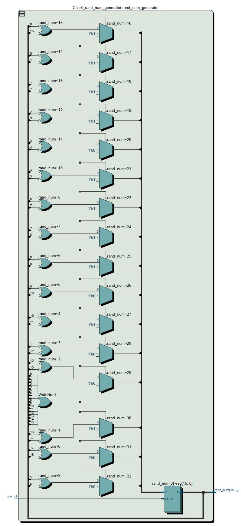
275 7

276 7.. bcd.sv 7..6 memory.sv 7

277 7..7 Chip8 SoundController.sv 76

278 7..8 Entire Design 77
Chip-8 Design Specification
 Columbia University Embedded Systems 4840 Chip-8 Design Specification Authors: Ashley Kling (ask2203) Levi Oliver (lpo2105) Gabrielle Taylor (gat2118) David Watkins (djw2146) Supervisor: Prof. Stephen
 Chapter 1 Microprocessor architecture ECE 3120 Dr. Mohamed Mahmoud http://iweb.tntech.edu/mmahmoud/ mmahmoud@tntech.edu Outline 1.1 Computer hardware organization 1.1.1 Number System 1.1.2 Computer hardware
The CPU and Memory. How does a computer work? How does a computer interact with data? How are instructions performed? Recall schematic diagram:
 The CPU and Memory How does a computer work? How does a computer interact with data? How are instructions performed? Recall schematic diagram: 1 Registers A register is a permanent storage location within
Memory Addressing, Binary, and Hexadecimal Review
 C++ By A EXAMPLE Memory Addressing, Binary, and Hexadecimal Review You do not have to understand the concepts in this appendix to become well-versed in C++. You can master C++, however, only if you spend
EE 271 Final Project - Towers of Hanoi
 EE 271 Final Project - Towers of Hanoi Siyu Jian, Michael Molina, Kendrick Tang December 6, 2012 We all worked Abstract In this project, we designed and implemented the game of tower of Hanoi on the DE1
Digital System Design Using Verilog. - Processing Unit Design
 Digital System Design Using Verilog - Processing Unit Design 1.1 CPU BASICS A typical CPU has three major components: (1) Register set, (2) Arithmetic logic unit (ALU), and (3) Control unit (CU) The register
(Refer Slide Time: 1:40)
") Computer Architecture Prof. Anshul Kumar Department of Computer Science and Engineering, Indian Institute of Technology, Delhi Lecture - 3 Instruction Set Architecture - 1 Today I will start discussion
Computer Architecture Prof. Anshul Kumar Department of Computer Science and Engineering, Indian Institute of Technology, Delhi Lecture - 3 Instruction Set Architecture - 1 Today I will start discussion
CS401 - Computer Architecture and Assembly Language Programming Glossary By
 CS401 - Computer Architecture and Assembly Language Programming Glossary By absolute address : A virtual (not physical) address within the process address space that is computed as an absolute number.
Microprocessors and Microcontrollers Prof. Santanu Chattopadhyay Department of E & EC Engineering Indian Institute of Technology, Kharagpur
 Microprocessors and Microcontrollers Prof. Santanu Chattopadhyay Department of E & EC Engineering Indian Institute of Technology, Kharagpur Lecture - 09 8085 Microprocessors (Contd.) (Refer Slide Time:
8086 INTERNAL ARCHITECTURE
 8086 INTERNAL ARCHITECTURE Segment 2 Intel 8086 Microprocessor The 8086 CPU is divided into two independent functional parts: a) The Bus interface unit (BIU) b) Execution Unit (EU) Dividing the work between
Wednesday, February 4, Chapter 4
 Wednesday, February 4, 2015 Topics for today Introduction to Computer Systems Static overview Operation Cycle Introduction to Pep/8 Features of the system Operational cycle Program trace Categories of
Chapter 1. Microprocessor architecture ECE Dr. Mohamed Mahmoud.
 Chapter 1 Microprocessor architecture ECE 3130 Dr. Mohamed Mahmoud The slides are copyright protected. It is not permissible to use them without a permission from Dr Mahmoud http://www.cae.tntech.edu/~mmahmoud/
Microcomputer Architecture and Programming
 IUST-EE (Chapter 1) Microcomputer Architecture and Programming 1 Outline Basic Blocks of Microcomputer Typical Microcomputer Architecture The Single-Chip Microprocessor Microprocessor vs. Microcontroller
Job Posting (Aug. 19) ECE 425. ARM7 Block Diagram. ARM Programming. Assembly Language Programming. ARM Architecture 9/7/2017. Microprocessor Systems
 ECE 425. ARM7 Block Diagram. ARM Programming. Assembly Language Programming. ARM Architecture 9/7/2017. Microprocessor Systems") Job Posting (Aug. 19) ECE 425 Microprocessor Systems TECHNICAL SKILLS: Use software development tools for microcontrollers. Must have experience with verification test languages such as Vera, Specman,
Job Posting (Aug. 19) ECE 425 Microprocessor Systems TECHNICAL SKILLS: Use software development tools for microcontrollers. Must have experience with verification test languages such as Vera, Specman,
ECE 571 Advanced Microprocessor-Based Design Lecture 3
 ECE 571 Advanced Microprocessor-Based Design Lecture 3 Vince Weaver http://web.eece.maine.edu/~vweaver vincent.weaver@maine.edu 30 January 2018 Homework #1 was posted Announcements 1 Microprocessors Also
MICROPROCESSOR AND MICROCONTROLLER BASED SYSTEMS
 MICROPROCESSOR AND MICROCONTROLLER BASED SYSTEMS UNIT I INTRODUCTION TO 8085 8085 Microprocessor - Architecture and its operation, Concept of instruction execution and timing diagrams, fundamentals of
a, b sum module add32 sum vector bus sum[31:0] sum[0] sum[31]. sum[7:0] sum sum overflow module add32_carry assign
![a, b sum module add32 sum vector bus sum[31:0] sum[0] sum[31]. sum[7:0] sum sum overflow module add32_carry assign](/thumbs/91/106466219.jpg "a, b sum module add32 sum vector bus sum[31:0] sum[0] sum[31]. sum[7:0] sum sum overflow module add32_carry assign") I hope you have completed Part 1 of the Experiment. This lecture leads you to Part 2 of the experiment and hopefully helps you with your progress to Part 2. It covers a number of topics: 1. How do we specify
I hope you have completed Part 1 of the Experiment. This lecture leads you to Part 2 of the experiment and hopefully helps you with your progress to Part 2. It covers a number of topics: 1. How do we specify
The MARIE Architecture
 The MARIE Machine Architecture that is Really Intuitive and Easy. We now define the ISA (Instruction Set Architecture) of the MARIE. This forms the functional specifications for the CPU. Basic specifications
Computer Science 324 Computer Architecture Mount Holyoke College Fall Topic Notes: MIPS Instruction Set Architecture
 Computer Science 324 Computer Architecture Mount Holyoke College Fall 2009 Topic Notes: MIPS Instruction Set Architecture vonneumann Architecture Modern computers use the vonneumann architecture. Idea:
Rui Wang, Assistant professor Dept. of Information and Communication Tongji University.
 Instructions: ti Language of the Computer Rui Wang, Assistant professor Dept. of Information and Communication Tongji University it Email: ruiwang@tongji.edu.cn Computer Hierarchy Levels Language understood
Microcontroller Systems
 µcontroller systems 1 / 43 Microcontroller Systems Engineering Science 2nd year A2 Lectures Prof David Murray david.murray@eng.ox.ac.uk www.robots.ox.ac.uk/ dwm/courses/2co Michaelmas 2014 µcontroller
Module 5 - CPU Design
 Module 5 - CPU Design Lecture 1 - Introduction to CPU The operation or task that must perform by CPU is: Fetch Instruction: The CPU reads an instruction from memory. Interpret Instruction: The instruction
CS/EE 3710 Computer Architecture Lab Checkpoint #2 Datapath Infrastructure
 CS/EE 3710 Computer Architecture Lab Checkpoint #2 Datapath Infrastructure Overview In order to complete the datapath for your insert-name-here machine, the register file and ALU that you designed in checkpoint
V8-uRISC 8-bit RISC Microprocessor AllianceCORE Facts Core Specifics VAutomation, Inc. Supported Devices/Resources Remaining I/O CLBs
 V8-uRISC 8-bit RISC Microprocessor February 8, 1998 Product Specification VAutomation, Inc. 20 Trafalgar Square Nashua, NH 03063 Phone: +1 603-882-2282 Fax: +1 603-882-1587 E-mail: sales@vautomation.com
Chapter 4. MARIE: An Introduction to a Simple Computer
 Chapter 4 MARIE: An Introduction to a Simple Computer Chapter 4 Objectives Learn the components common to every modern computer system. Be able to explain how each component contributes to program execution.
Chapter 2A Instructions: Language of the Computer
 Chapter 2A Instructions: Language of the Computer Copyright 2009 Elsevier, Inc. All rights reserved. Instruction Set The repertoire of instructions of a computer Different computers have different instruction
Wednesday, September 13, Chapter 4
 Wednesday, September 13, 2017 Topics for today Introduction to Computer Systems Static overview Operation Cycle Introduction to Pep/9 Features of the system Operational cycle Program trace Categories of
Chapter Operation Pinout Operation 35
 68000 Operation 35 Chapter 6 68000 Operation 6-1. 68000 Pinout We will do no construction in this chapter; instead, we will take a detailed look at the individual pins of the 68000 and what they do. Fig.
Contents. Slide Set 1. About these slides. Outline of Slide Set 1. Typographical conventions: Italics. Typographical conventions. About these slides
 Slide Set 1 for ENCM 369 Winter 2014 Lecture Section 01 Steve Norman, PhD, PEng Electrical & Computer Engineering Schulich School of Engineering University of Calgary Winter Term, 2014 ENCM 369 W14 Section
Grundlagen Microcontroller Processor Core. Günther Gridling Bettina Weiss
 Grundlagen Microcontroller Processor Core Günther Gridling Bettina Weiss 1 Processor Core Architecture Instruction Set Lecture Overview 2 Processor Core Architecture Computes things > ALU (Arithmetic Logic
FPGA IMPLEMENTATION OF A PROCESSOR THROUGH VERILOG
 FPGA IMPLEMENTATION OF A PROCESSOR THROUGH VERILOG Overview and tutorial by Sagnik Nath Objective 1 About the single cycle ARM microarchitecture 1 Design Process 2 Creating Flow for Instruction set 3 LDR
CPU Design John D. Carpinelli, All Rights Reserved 1
 CPU Design 1997 John D. Carpinelli, All Rights Reserved 1 Outline Register organization ALU design Stacks Instruction formats and types Addressing modes 1997 John D. Carpinelli, All Rights Reserved 2 We
Topic Notes: MIPS Instruction Set Architecture
 Computer Science 220 Assembly Language & Comp. Architecture Siena College Fall 2011 Topic Notes: MIPS Instruction Set Architecture vonneumann Architecture Modern computers use the vonneumann architecture.
Chapter 4. MARIE: An Introduction to a Simple Computer. Chapter 4 Objectives. 4.1 Introduction. 4.2 CPU Basics
 Chapter 4 Objectives Learn the components common to every modern computer system. Chapter 4 MARIE: An Introduction to a Simple Computer Be able to explain how each component contributes to program execution.
Computer Architecture Prof. Smruti Ranjan Sarangi Department of Computer Science and Engineering Indian Institute of Technology, Delhi
 Computer Architecture Prof. Smruti Ranjan Sarangi Department of Computer Science and Engineering Indian Institute of Technology, Delhi Lecture - 11 X86 Assembly Language Part-II (Refer Slide Time: 00:25)
8051 Overview and Instruction Set
 8051 Overview and Instruction Set Curtis A. Nelson Engr 355 1 Microprocessors vs. Microcontrollers Microprocessors are single-chip CPUs used in microcomputers Microcontrollers and microprocessors are different
1 MALP ( ) Unit-1. (1) Draw and explain the internal architecture of 8085.
 Unit-1. (1) Draw and explain the internal architecture of 8085.") (1) Draw and explain the internal architecture of 8085. The architecture of 8085 Microprocessor is shown in figure given below. The internal architecture of 8085 includes following section ALU-Arithmetic
(1) Draw and explain the internal architecture of 8085. The architecture of 8085 Microprocessor is shown in figure given below. The internal architecture of 8085 includes following section ALU-Arithmetic
Lesson 5: Verifying RAMs with the Fluke 9010A Version 1.03
 Lesson 5: Verifying RAMs with the Fluke 9010A Version 1.03 Random Access Memory: One of the most common failures that occur on arcade PCBS are failures in Random Access Memory (RAM). These failures will
Chapter 3. Z80 Instructions & Assembly Language. Von Neumann Architecture. Memory. instructions. program. data
 Von Neumann Architecture The von Neumann architecture is a computer design model that uses a processing unit and a separate storage to hold both instructions and data To run a machine, program and data
CS 24: INTRODUCTION TO. Spring 2018 Lecture 3 COMPUTING SYSTEMS
 CS 24: INTRODUCTION TO Spring 2018 Lecture 3 COMPUTING SYSTEMS LAST TIME Basic components of processors: Buses, multiplexers, demultiplexers Arithmetic/Logic Unit (ALU) Addressable memory Assembled components
1. Internal Architecture of 8085 Microprocessor
 1. Internal Architecture of 8085 Microprocessor Control Unit Generates signals within up to carry out the instruction, which has been decoded. In reality causes certain connections between blocks of the
DC57 COMPUTER ORGANIZATION JUNE 2013
 Q2 (a) How do various factors like Hardware design, Instruction set, Compiler related to the performance of a computer? The most important measure of a computer is how quickly it can execute programs.
TEACHING COMPUTER ARCHITECTURE THROUGH DESIGN PRACTICE. Guoping Wang 1. INTRODUCTION
 TEACHING COMPUTER ARCHITECTURE THROUGH DESIGN PRACTICE Guoping Wang Indiana University Purdue University Fort Wayne, Indiana; Email:wang@engr.ipfw.edu 1. INTRODUCTION Computer Architecture is a common
Design of Decode, Control and Associated Datapath Units
 1 Design of Decode, Control and Associated Datapath Units ECE/CS 3710 - Computer Design Lab Lab 3 - Due Date: Thu Oct 18 I. OVERVIEW In the previous lab, you have designed the ALU and hooked it up with
EECS 151/251 FPGA Project Report
 EECS 151/251 FPGA Project Report GSI: Vighnesh Iyer Team Number: 6 Partners: Ashwinlal Sreelal and Zhixin Alice Ye Due Date: Dec 9, 2016 Part I: Project Description The aims of this project were to develop
Practical Malware Analysis
 Practical Malware Analysis Ch 4: A Crash Course in x86 Disassembly Revised 1-16-7 Basic Techniques Basic static analysis Looks at malware from the outside Basic dynamic analysis Only shows you how the
Functional Units of a Modern Computer
 Functional Units of a Modern Computer We begin this lecture by repeating a figure from a previous lecture. Logically speaking a computer has four components. Connecting the Components Early schemes for
CSEE W4840 Embedded System Design Lab 1
 CSEE W4840 Embedded System Design Lab 1 Stephen A. Edwards Due January 31, 2008 Abstract Learn to use the Altera Quartus development envrionment and the DE2 boards by implementing a small hardware design
Introduction to Computers - Chapter 4
 Introduction to Computers - Chapter 4 Since the invention of the transistor and the first digital computer of the 1940s, computers have been increasing in complexity and performance; however, their overall
The Itanium Bit Microprocessor Report
 The Itanium - 1986 8 Bit Microprocessor Report By PRIYANK JAIN (02010123) Group # 11 Under guidance of Dr. J. K. Deka & Dr. S. B. Nair Department of Computer Science & Engineering Indian Institute of Technology,
CS 101, Mock Computer Architecture
 CS 101, Mock Computer Architecture Computer organization and architecture refers to the actual hardware used to construct the computer, and the way that the hardware operates both physically and logically
COMPUTER ORGANIZATION AND DESIGN
 ARM COMPUTER ORGANIZATION AND DESIGN Edition The Hardware/Software Interface Chapter 4 The Processor Modified and extended by R.J. Leduc - 2016 To understand this chapter, you will need to understand some
Explanation of PIC 16F84A processor data sheet Part 1: overview of the basics
 Explanation of PIC 16F84A processor data sheet Part 1: overview of the basics This report is the first of a three part series that discusses the features of the PIC 16F94A processor. The reports will refer
COSC 122 Computer Fluency. Computer Organization. Dr. Ramon Lawrence University of British Columbia Okanagan
 COSC 122 Computer Fluency Computer Organization Dr. Ramon Lawrence University of British Columbia Okanagan ramon.lawrence@ubc.ca Key Points 1) The standard computer (von Neumann) architecture consists
2.2 THE MARIE Instruction Set Architecture
 2.2 THE MARIE Instruction Set Architecture MARIE has a very simple, yet powerful, instruction set. The instruction set architecture (ISA) of a machine specifies the instructions that the computer can perform
Computer Architecture Prof. Mainak Chaudhuri Department of Computer Science & Engineering Indian Institute of Technology, Kanpur
 Computer Architecture Prof. Mainak Chaudhuri Department of Computer Science & Engineering Indian Institute of Technology, Kanpur Lecture - 7 Case study with MIPS-I So, we were discussing (Refer Time: 00:20),
EE 3170 Microcontroller Applications
 EE 3170 Microcontroller Applications Lecture 4 : Processors, Computers, and Controllers - 1.2 (reading assignment), 1.3-1.5 Based on slides for ECE3170 by Profs. Kieckhafer, Davis, Tan, and Cischke Outline
ECE2049 E17 Lecture 4 MSP430 Architecture & Intro to Digital I/O
 ECE2049-E17 Lecture 4 1 ECE2049 E17 Lecture 4 MSP430 Architecture & Intro to Digital I/O Administrivia Homework 1: Due today by 7pm o Either place in box in ECE office or give to me o Office hours tonight!
Computer Organization and Technology Processor and System Structures
 Computer Organization and Technology Processor and System Structures Assoc. Prof. Dr. Wattanapong Kurdthongmee Division of Computer Engineering, School of Engineering and Resources, Walailak University
COPYRIGHTED MATERIAL. An Introduction to Computers That Will Actually Help You in Life. Chapter 1. Memory: Not Exactly 0s and 1s. Memory Organization
 Chapter 1 An Introduction to Computers That Will Actually Help You in Life Memory: Not Exactly 0s and 1s Memory Organization A Very Simple Computer COPYRIGHTED MATERIAL 2 Chapter 1 An Introduction to Computers
CS 24: INTRODUCTION TO. Spring 2015 Lecture 2 COMPUTING SYSTEMS
 CS 24: INTRODUCTION TO Spring 2015 Lecture 2 COMPUTING SYSTEMS LAST TIME! Began exploring the concepts behind a simple programmable computer! Construct the computer using Boolean values (a.k.a. bits )
These three counters can be programmed for either binary or BCD count.
 S5 KTU 1 PROGRAMMABLE TIMER 8254/8253 The Intel 8253 and 8254 are Programmable Interval Timers (PTIs) designed for microprocessors to perform timing and counting functions using three 16-bit registers.
ASSEMBLY LANGUAGE MACHINE ORGANIZATION
 ASSEMBLY LANGUAGE MACHINE ORGANIZATION CHAPTER 3 1 Sub-topics The topic will cover: Microprocessor architecture CPU processing methods Pipelining Superscalar RISC Multiprocessing Instruction Cycle Instruction
Introduction to Assembly language
 Introduction to Assembly language 1 USING THE AVR MICROPROCESSOR Outline Introduction to Assembly Code The AVR Microprocessor Binary/Hex Numbers Breaking down an example microprocessor program AVR instructions
Unit 2 : Computer and Operating System Structure
 Unit 2 : Computer and Operating System Structure Lesson 1 : Interrupts and I/O Structure 1.1. Learning Objectives On completion of this lesson you will know : what interrupt is the causes of occurring
Chapter 5 - Input / Output
 Chapter 5 - Input / Output Luis Tarrataca luis.tarrataca@gmail.com CEFET-RJ L. Tarrataca Chapter 5 - Input / Output 1 / 90 1 Motivation 2 Principle of I/O Hardware I/O Devices Device Controllers Memory-Mapped
Processing Unit CS206T
 Processing Unit CS206T Microprocessors The density of elements on processor chips continued to rise More and more elements were placed on each chip so that fewer and fewer chips were needed to construct
CS Computer Architecture
 CS 35101 Computer Architecture Section 600 Dr. Angela Guercio Fall 2010 An Example Implementation In principle, we could describe the control store in binary, 36 bits per word. We will use a simple symbolic
Recommended Design Techniques for ECE241 Project Franjo Plavec Department of Electrical and Computer Engineering University of Toronto
 Recommed Design Techniques for ECE241 Project Franjo Plavec Department of Electrical and Computer Engineering University of Toronto DISCLAIMER: The information contained in this document does NOT contain
CS 64 Week 0 Lecture 1. Kyle Dewey
 CS 64 Week 0 Lecture 1 Kyle Dewey Overview Administrative stuff Class motivation Syllabus Working with different bases Bitwise operations Twos complement Administrative Stuff About Me 5th year Ph.D. candidate,
11. A Computing Machine
 COMPUTER SCIENCE S E D G E W I C K / W A Y N E Computer Science Including Programming in Java 11. A Computing Machine Section 5.1 http://introcs.cs.princeton.edu COMPUTER SCIENCE S E D G E W I C K / W
PESIT Bangalore South Campus
 INTERNAL ASSESSMENT TEST I Date: 30/08/2017 Max Marks: 40 Subject & Code: Computer Organization 15CS34 Semester: III (A & B) Name of the faculty: Mrs.Sharmila Banu.A Time: 8.30 am 10.00 am Answer any FIVE
MARIE: An Introduction to a Simple Computer
 MARIE: An Introduction to a Simple Computer Outline Learn the components common to every modern computer system. Be able to explain how each component contributes to program execution. Understand a simple
SOEN228, Winter Revision 1.2 Date: October 25,
 SOEN228, Winter 2003 Revision 1.2 Date: October 25, 2003 1 Contents Flags Mnemonics Basic I/O Exercises Overview of sample programs 2 Flag Register The flag register stores the condition flags that retain
Chapter 7 Central Processor Unit (S08CPUV2)
") Chapter 7 Central Processor Unit (S08CPUV2) 7.1 Introduction This section provides summary information about the registers, addressing modes, and instruction set of the CPU of the HCS08 Family. For a more
Chapter 7 Central Processor Unit (S08CPUV2) 7.1 Introduction This section provides summary information about the registers, addressing modes, and instruction set of the CPU of the HCS08 Family. For a more
Description of the Simulator
 Description of the Simulator The simulator includes a small sub-set of the full instruction set normally found with this style of processor. It includes advanced instructions such as CALL, RET, INT and
Advanced Parallel Architecture Lesson 3. Annalisa Massini /2015
 Advanced Parallel Architecture Lesson 3 Annalisa Massini - Von Neumann Architecture 2 Two lessons Summary of the traditional computer architecture Von Neumann architecture http://williamstallings.com/coa/coa7e.html
Familiarity with data types, data structures, as well as standard program design, development, and debugging techniques.
 EE 472 Lab 1 (Individual) Introduction to C and the Lab Environment University of Washington - Department of Electrical Engineering Introduction: This lab has two main purposes. The first is to introduce
Control Unit: The control unit provides the necessary timing and control Microprocessor resembles a CPU exactly.
 Unit I 8085 and 8086 PROCESSOR Introduction to microprocessor A microprocessor is a clock-driven semiconductor device consisting of electronic logic circuits manufactured by using either a large-scale
Name EGR 2131 Lab #6 Number Representation and Arithmetic Circuits
 Name EGR 2131 Lab #6 Number Representation and Arithmetic Circuits Equipment and Components Quartus software and Altera DE2-115 board PART 1: Number Representation in Microsoft Calculator. First, let s
1. INTRODUCTION TO MICROPROCESSOR AND MICROCOMPUTER ARCHITECTURE:
 1. INTRODUCTION TO MICROPROCESSOR AND MICROCOMPUTER ARCHITECTURE: A microprocessor is a programmable electronics chip that has computing and decision making capabilities similar to central processing unit
CPE 323 MSP430 INSTRUCTION SET ARCHITECTURE (ISA)
") CPE 323 MSP430 INSTRUCTION SET ARCHITECTURE (ISA) Aleksandar Milenković Email: milenka@uah.edu Web: http://www.ece.uah.edu/~milenka Objective Introduce MSP430 Instruction Set Architecture (Class of ISA,
CPE 323 MSP430 INSTRUCTION SET ARCHITECTURE (ISA) Aleksandar Milenković Email: milenka@uah.edu Web: http://www.ece.uah.edu/~milenka Objective Introduce MSP430 Instruction Set Architecture (Class of ISA,
UNIT - V MEMORY P.VIDYA SAGAR ( ASSOCIATE PROFESSOR) Department of Electronics and Communication Engineering, VBIT
 Department of Electronics and Communication Engineering, VBIT") UNIT - V MEMORY P.VIDYA SAGAR ( ASSOCIATE PROFESSOR) contents Memory: Introduction, Random-Access memory, Memory decoding, ROM, Programmable Logic Array, Programmable Array Logic, Sequential programmable
UNIT - V MEMORY P.VIDYA SAGAR ( ASSOCIATE PROFESSOR) contents Memory: Introduction, Random-Access memory, Memory decoding, ROM, Programmable Logic Array, Programmable Array Logic, Sequential programmable
Computer Science 324 Computer Architecture Mount Holyoke College Fall Topic Notes: MIPS Instruction Set Architecture
 Computer Science 324 Computer Architecture Mount Holyoke College Fall 2007 Topic Notes: MIPS Instruction Set Architecture vonneumann Architecture Modern computers use the vonneumann architecture. Idea:
Computer Architecture
 Computer Architecture Chapter 2 Instructions: Language of the Computer Fall 2005 Department of Computer Science Kent State University Assembly Language Encodes machine instructions using symbols and numbers
Dec Hex Bin ORG ; ZERO. Introduction To Computing
 Dec Hex Bin 0 0 00000000 ORG ; ZERO Introduction To Computing OBJECTIVES this chapter enables the student to: Convert any number from base 2, base 10, or base 16 to any of the other two bases. Add and
Computer Graphics Prof. Sukhendu Das Dept. of Computer Science and Engineering Indian Institute of Technology, Madras Lecture - 14
 Computer Graphics Prof. Sukhendu Das Dept. of Computer Science and Engineering Indian Institute of Technology, Madras Lecture - 14 Scan Converting Lines, Circles and Ellipses Hello everybody, welcome again
6.111 Final Project Jonathan Downey Lauri Kauppila Brian Myhre
 6.111 Final Project Jonathan Downey Lauri Kauppila Brian Myhre Project Motivation Distinct Sub-systems Complex Behavior and Architecture FPGA Required Not Possible with Microcontroller Large Amount of
Real Time Spectrogram
 Real Time Spectrogram EDA385 Final Report Erik Karlsson, dt08ek2@student.lth.se David Winér, ael09dwi@student.lu.se Mattias Olsson, ael09mol@student.lu.se October 31, 2013 Abstract Our project is about
Major and Minor States
 Major and Minor States We now consider the micro operations and control signals associated with the execution of each instruction in the ISA. The execution of each instruction is divided into three phases.
COMP12111 Fundamentals of Computer Engineering Paul Nutter Vasilis Pavlidis Comments
 Fundamentals of Computer Engineering Paul Nutter Vasilis Pavlidis Comments Please see the attached report. 12 February 2016 Page 2 of 7 Exam Feedback 2015/16 Q1 set by Paul Nutter Q2 set by Vasilis Pavlidis
Lecture V Toy Hardware and Operating System
 2. THE Machine Lecture V Page 1 Lecture V Toy Hardware and Operating System 1. Introduction For use in our OS projects, we introduce THE Machine where THE is an acronym 1 for Toy HardwarE. We also introduce
17.1. Unit 17. Instruction Sets Picoblaze Processor
 17.1 Unit 17 Instruction Sets Picoblaze Processor INSTRUCTION SET OVERVIEW 17.2 17.3 Instruction Set Review Defines the software interface of the processor and memory system Instruction set is the vocabulary
Qsys and IP Core Integration
 Qsys and IP Core Integration Stephen A. Edwards (after David Lariviere) Columbia University Spring 2016 IP Cores Altera s IP Core Integration Tools Connecting IP Cores IP Cores Cyclone V SoC: A Mix of
ENGR 2031 Digital Design Laboratory Lab 7 Background
 ENGR 2031 Digital Design Laboratory Lab 7 Background What we will cover Overview of the Simple Computer (scomp) Architecture Register Flow Diagrams VHDL Implementation of scomp Lab 7 scomp Architecture
CPU: SOFTWARE ARCHITECTURE INSTRUCTION SET (PART
 General Introduction CPU: SOFTWARE ARCHITECTURE INSTRUCTION SET (PART 1) General Introduction (1/5): On Instructions Instruction operate with data or with the flow of the program The following information
A microprocessor-based system
 7 A microprocessor-based system How simple can a microprocessor-based system actually be? It must obviously contain a microprocessor otherwise it is simply another electronic circuit. A microprocessor
Programmable machines
 Page 1 of 9 Programmable machines indicates problems that have been selected for discussion in section, time permitting. Problem 1. Consider the following circuit: The heavy lines represent busses, which
Digital IP Cell 8-bit Microcontroller PE80
 1. Description The is a Z80 compliant processor soft-macro - IP block that can be implemented in digital or mixed signal ASIC designs. The Z80 and its derivatives and clones make up one of the most commonly
x86 architecture et similia
 x86 architecture et similia 1 FREELY INSPIRED FROM CLASS 6.828, MIT A full PC has: PC architecture 2 an x86 CPU with registers, execution unit, and memory management CPU chip pins include address and data