APK INSTALLATION GUIDE
|
|
|
- Patrick Robertson
- 5 years ago
- Views:
Transcription


1 Rev 1.3 Dated 9/17/2008 APK INSTALLATION GUIDE This equipment has been tested and found to comply with the limits for a Class A digital device, pursuant to part 15 of the FCC Rules. These limits are designated to provide reasonable protection against harmful interference when the equipment is operated in a commercial environment. This equipment generates, uses, and can radiate radio frequency energy and, if not installed and used in accordance with the instruction manual, may cause harmful interference to radio communications. Operation of this equipment in a residential area is likely to cause harmful interference, in which case the users will be required to correct the interference at there own expense. APK INSTALLATION GUIDE Instructions contained in this Installation guide should be performed only by qualified persons in accordance with local and national codes. Kele, Inc and its affiliates assume no responsibility for any consequences related to the improper use of this manual. Guidelines for Mounting APK-kits Within a Relay Panel Mounting locations within the panel are limited by the interior area provided. Install mounting plates in a location near or central to the relays or circuit breakers it will interface with. Twelve inch pigtails are available as an option to splice with wires from relays. Distances between ribbon cable sockets of the electronic boards must not be greater than the lengths of ribbon cable that connect them. If using two interface boards instead of one, be sure to differentiate between boards A and B. Mount plates such that cross-board wiring (relay interface wires lying across boards) is minimized. APK-kits provide the flexibility to mount anywhere within the low voltage section of the existing lighting control panel. APK-kits do not fit all panels that contain compatible relays. Appendix A illustrates electronic board mounting configurations for most panels that are compatible with APK-kits. Some legacy panels are not listed. If your installation contains panels not included on these pages, please contact Kele, Inc to determine if your panels are compatible. If you are upgrading a panel that is listed in Appendix A, you may use the mounting configuration illustrated for that panel to obtain a mounting location and orientation for each board of the APK-kit. The mounting configurations shown there are recommendations and do not have to be followed. The configurations were developed using certain parameters that determine where and how APK-kits are installed in the lighting panels. See Guidelines for Mounting APK-kits Within a Relay Panel below. Directions for installing the modules within a relay panel follow. Each APK-kit comes with one or two interface boards. Additional boards can be ordered separately for panels with up to 60 relays. Whether using Appendix A or the guidelines listed above to mount the Kits, it is helpful to be able to distinguish the difference between the interface boards when mounting. Each RIB (Relay Interface Board) board is designed to interface with a specific group of relays. This installation guide designates each interface board per kit as A or B. Board A interfaces relays 1-16 (1-30 for APK4) and B interfaces There is no way to assign such names in the controller software to notify the controller where the inputs are coming from; the controller is able to distinguish inputs from each board through the ribbon cable sockets. Figures 1 A-C shows the locations of these sockets on the LMB and interface boards for each kit type. The APK2, APK3, APK5 Series Kits all follow the same design for ribbon cable connections. Examine the RIB boards of your kit. Notice, the ribbon cable socket is shifted between board A and B. Each position is labeled 1-16 or The APK4 kit uses only one RIB board.
2 INDEX OVERVIEW... 3 APK COMPONENTS APK KIT EXAMPLE REMOVING THE EXISTING LIGHTING CONTROL SYSTEM 8 MOUNTING ELECTRONIC BOARDS IN RELAY PANEL 8 CONNECTING RIBBON CABLES 8 CONNECTION POWER TO THE AUTOPHOS APK CONTROLLER CONNECTING POWER WIRES BETWEEN CONTROLLER AND RIB 10 APK4 POWER CONNECTIONS CONNECTING RELAY 12 OPTIONAL PIGTAILS FOR APK3, APK4, AND APK APK2 CONNECTING RELAYS 12 APK3 CONNECTING RELAYS 13 APK4 CONNECTING RELAYS 14 APK5 CONNECTING RELAYS 15 SWITCH INPUTS and JUMPERS. 16 ANALOG INPUTS. 18 CONNECTING THE RS AUTOPHOS ADDRESSABLE SWITCH (APDAS) NETWORK 21 OPTIONAL EXPANSION PARTS FOR THE APK KITS TROUBLESHOOTING THE AUTOPHOS CONTROLLER 22 APPENDIX A: APK COMPATIBLE PANELS AND MOUNTING..23 2
3 Overview The APK (AUTOPHOS RETROFIT KIT) series provide the flexibility to mount anywhere within the low voltage section of the existing lighting control panel. APK's do not fit all panels that contain compatible relays. Appendix A illustrates electronic board mounting configurations for most panels that are compatible with APK's. Some legacy panels are not listed. If your installation contains panels not included on these pages, please contact Kele, Inc to determine if your panels are compatible. If you are upgrading a panel that is listed in Appendix A, you may use the mounting configuration illustrated for that panel to obtain a mounting location and orientation for each board of the APK. The mounting configurations shown there are recommendations and do not have to be followed. The configurations were developed using certain parameters that determine where and how APK's are installed in the lighting panels. See Guidelines for Mounting APK's Within a Relay Panel below. Directions for installing the modules within a relay panel follow. The APK s are designed to upgrade existing lighting control relay panels without having to replace entire relay panels. The APK Series includes the APK2, APK3, APK4, and APK5. These Kits are designed to upgrade lighting control systems utilizing the following relays shown in Table 1 below: TABLE 1 PANEL TYPE APK2 2-Wire APK3 3-Wire APK4 4-Wire APK5 5-Wire General RR7 RR9 Electric Horton RR7 RR9 Controls Wattstopper RR7 RR9 Lithonia Lighting RR7 RR9 Douglas WE- RR7 WR /6162/69172/6221 ILC 2R7,2PC 2R7 2PC 2R9 MicroLite RR7 MLR-020 Johnson Controls ILC Touch-Plate RR7 RR7 JCI-ILC 3000/4000-PL Installing APK s involves working only with low voltage electronics and wiring. The installer does not need to remove relay panels nor relays. Only the electronics and wires connected to the relays need to be removed and replaced with Kele, Inc kit. The following pages of this install guide discuss how to install each of these Kits into the relay panels they were designed to integrate with. APK Components All APK s include a Lighting control Main Board controller (LMB) and two Relay Interface Boards (RIB). The controller is programmed using Kele LPPK Software. The LMB communicates with the relay through the RIB boards. Communications with the interface boards are through one or more ribbon cables supplied with the kit. APK2, APK3, and APK4 Series use RIB boards with 16 relay output capacity. Two boards give a maximum capacity of 32 relays. The APK5 uses one RIB board with a relay capacity of 30. In relay applications requiring more than the provided capacity, additional RIB boards and cables can be ordered (APK2X, APK3X, APK4X, APK5X). 3

4 1. Power LED, Run LED, Error LED Power LED should be on solid as long as AutoPhos controller is connected to 24VAC. Run LED should always be blinking for normal processor activity. Error LED will briefly blink during power up or memory upload then should go to off and remain off show processor memory in normal state. 2. Access Port is used for firmware flash upgrades in the field. Use cable APT for this purpose. 3. Access Rx and Tx LEDs show, receive and transmit activity on the 5-pin Access port. 4. Not used on this control platform 5. Not used on this control platform 6. Not used on this control platform 4
5 7. BTS485 socket receives BTS-485 terminating resistor when (rarely) needed on a 485 network. 8. EIA-485 Network Port is the main port used for RS485 communications with the building automation system. On board isolation circuitry provides 500-volt isolation for the RS485 communication network. The terminal blocks can be removed from the AutoPhos controller for easy installation or for quick replacement of an AutoPhos controller. 9. EIA-485 Network Port Rx and Tx LEDs show receive and transmit activity on the RS485 network. 10. Multifunction Dip Switch (Hundreds, SW1) is used to set address and baud rate for AutoPhos controller on the RS485 network. #1-6 are for baud rate settings. For address >99, #7 Up = 200, #8 Up= 100. (#8 ignored when #7 is up, maximum address is 255) 11. Rotary Switch (Tens, SW3) is used to set address 1-99 for AutoPhos controller on RS485 network. 12. Rotary switch (Units, SW4) is used to set address 1-99 for AutoPhos controller on RS485 network. 13. Auto Button (SW2) is used to return AutoPhos controller outputs to pre-override state (Auto Mode) after Over Button is used. Pressing Auto will return AutoPhos controller to pre-override state and will allow execution of serial commands that were stored during override mode. 14. Auto Button LED shows solid ON when AutoPhos controller is not in override state or overrideexpired state. LED blinking warns that there is no.lpx file loaded into firmware. 15. Over Button (SW5) is manual override of AutoPhos controller outputs. Press to override all outputs ON and press again to override all outputs OFF. AutoPhos controller will not execute serial commands while in override mode. Serial commands received during override mode are stored until AutoPhos controller is returned to Auto mode by pressing Auto button. With no button activity, AutoPhos controller will go to override-expired state after approximately 15 minutes and be able to execute subsequent incoming serial commands. To return AutoPhos controller outputs to full Auto mode, press Auto button at any time. 16. Over Button LED shows solid ON when all outputs are in manual override, blinking when all outputs are in manual override OFF. LED is off when AutoPhos controller is in Auto mode. 17. Legacy Port is not a field-accessible feature. 18. Format Pins can be shorted together to erase memory only if address set to zero. Do not use unless instructed to do so by technical support. Lost items will be BACnet control programs and.lpk file (from the configuration software). These can be restored through use of Lighting Panel Configuration Software (APSoft) with AppLoader programming tools. 19. AutoPhos controller/rcs Jumper is used to enable AutoPhos controller to control various legacy products. 20. RCS 14 Pin Port receives a 14-pin ribbon cable to control legacy products and retrofit kits. DO NOT hot swap this cable Pin Socket for Outputs 1-32 receives single ribbon cable including both relay 1-16 and relay output cards. 20-pin cable may have 16-pin connector on other end depending on type of relay interface card. DO NOT hot swap. Ribbon cable may be disconnected to disable outputs while programming or testing AutoPhos controller processor Pin Socket for Outputs receives single ribbon cable including both relay and relay output cards. 20-pin cable may have 16-pin connector on other end depending on type of relay interface card. (These 3rd and 4th RIB cards are identical to 1st and 2nd RIB cards). DO NOT hot swap. Ribbon cable may be disconnected disable outputs while programming or testing AutoPhos controller processor. 23. LEXP Socket provides connection of up to three optional input expansion modules using 20-pin ribbon cable. DO NOT hot swap this cable. 24. Input Power 24VAC transient protected, surge suppression to 1.8 joules. The terminal block can be removed from the AutoPhos controller for easy installation or for quick replacement of an AutoPhos controller. 5
6 25. Aux Power Tap for 24VAC accessories, runs off of input power, is interchangeable with input power pins. 26. Switch Inputs 1-16 for hard wire home run style override switches and occupancy sensors. The terminal blocks can be removed from the AutoPhos controller for easy installation or quick replacement of the entire controller. AutoPhos controller has 24 onboard input connections. 27. Jumper for Switch Inputs 9-16 for provides capability to select the AutoPhos Controller to power its inputs or allow an external power source to power its inputs. Occupancy sensors that use 24VDC to power the sensor are typical applications that are externally powering an input. Jumper in the N position configures the inputs to be dry contact and powered by the AutoPhos controller. Jumper in the opposite position configures the inputs to be externally powered by up to 24VDC. Each jumper affects only its respective eight inputs only. There is one jumper for each of the AutoPhos controller Controller s eight inputs. 28. Jumper for Switch Inputs 1-8 (See above) 29. Switch Inputs (See above) 30. Jumper for Switch Inputs (see above) 31. Battery Holder for battery replacement type CR-2032, 3 volt. Battery does not function as long as AutoPhos controller is powered. Battery is for backup of the real time clock and BACnet control programs during a power outage. All other programming is held in non-volatile memory. 32. Battery Jumper disengages battery same as if removing the battery. See previous entry. 33. Analog Inputs 1-6 provides 6 inputs for accepting 0-5 VDC signals from photo sensors such as Lumisys LS5 series. Power (5V) and return (G) are also provided to power the sensors from the AutoPhos controller. 34. Not used on this control platform 35. AutoPhos Digital Addressable Switch Network Port receives the 4-wire (Belden #1502P or equivalent) network for addressable override switches. The terminal blocks can be removed from the AutoPhos controller for easy installation or for quick replacement of an AutoPhos controller. 36. Jumper for AutoPhos Digital Addressable Switch Network switches the port from between two modes. Typically never touched. 37. AutoPhos Digital Addressable Switch Network Rx,Tx and Busy LEDs show the network outbound/inbound communication and processor activity. 6

7 APK KIT EXAMPLE: An Example of a APK kit (APK2). The Expansion kit is an optional expansion from 32 relays to 60 relays. Note that the APK4 is standard with 30-relay interface expandable to 60-relay interface with optional expansion kit. The APK (AUTOPHOS RETROFIT KIT) series provide the flexibility to mount anywhere within the low voltage section of the existing lighting control panel. APK's do not fit all panels that contain compatible relays. Appendix A illustrates electronic board mounting configurations for most panels that are compatible with APK's. Some legacy panels are not listed. If your installation contains panels not included on these pages, please contact Kele, Inc to determine if your panels are compatible. If you are upgrading a panel that is listed in Appendix A, you may use the mounting configuration illustrated for that panel to obtain a mounting location and orientation for each board of the APK. The mounting configurations shown there are recommendations and do not have to be followed. The configurations were developed using certain parameters that determine where and how APK's are installed in the lighting panels. Directions for installing the modules within a relay panel follow. The APK4 distinguishes Board A and B differently (B ordered separately as APK4X for up to 60 relay outputs) from the APK2, APK3, and APK5 series kits. Board A possesses two ribbon cable sockets: a 14-pin socket labeled CPU for communications with the AUTOPHOS Controller AUTOPHOS, and a 20-pin socket, 7
8 labeled AUX OUT, to communicate with Board B. Board B possesses only one ribbon cable socket for input from Board A. Refer to the APK4 installation for each board. Removing the Existing Lighting Control System WARNING! Switch OFF high voltage power to the existing lighting control relay panel before conducting any procedures described below 1. Cut existing low voltage wiring. Do not cut existing relay control wires too short. Wires can be cut as needed later when connecting them to the interface boards. See section, Connecting Relays on page Unbolt and remove existing controller electronics. Mounting Electronic Boards Within the Relay Panel CAUTION! The installer should be grounded before handling any electronic circuit boards. Static discharge can damage sensitive components. Handle carefully as components are also fragile. 1. Determine the mounting orientation and location of all electronic boards. 2. Use Appendix A or the guidelines listed to determine the best configuration to mount the modules within the panel. 3. Mount the AUTOPHOS Controller with its plate into the relay panel. Using the mounting holes provided in the plate, install the AUTOPHOS Controller into the panel using self-tapping screws. Keep the board clear of any metal shavings. 4. Mount interface Board A into the relay panel. Mount Board A in the position and orientation determined in Step 1. As with the AUTOPHOS CONTROLLER, Board A contains four mounting holes. Use self-tapping screws. Keep the board clear of any debris or metal shavings during installation. 5. Mount interface Board B (if required) into the relay panel. Follow the same procedure as with Step 3 for Board A. Connecting Ribbon Cables Each conversion kit is supplied with its own ribbon cable set. The pin count for each ribbon cable varies with each kit model. Pin counts and lengths of the cable are provided in Table 2 below. TABLE 2 Length (Inches) Length (Inches) Product Code Pin Count AUTOPHOS Controller to RIB-A RIB-A to RIB-B APK APK APK N/A APK


9 CAUTION! Disconnect power from AUTOPHOS CONTROLLER before installing or removing APK-kit ribbon cables. Failure to do so could result in board and/or relay damage. IMPORTANT: Ribbon cable connectors are keyed to fit slots on corresponding connector sockets on electronic boards. Do not force connectors into board sockets in the wrong orientation. Be sure keys and slots match. Do not insert the connector at angle to avoid damaging pins within the socket. 1. If you have already connected power to your APK-kit, disconnect power. 2. Refer to Figure 1 for 24 VAC power location to your AUTOPHOS CONTROLLER. 3. Verify ribbon cable pin counts according to Table 2. Verify that your cable has the correct pin count before attempting to install the cable. Generally, the ribbon cables are not hot-swappable under power. 4. Refer to Figures 3. Insert ribbon cable connectors into appropriate sockets. APK2, APK3, and APK5 series kits come with one 34 daisy chain ribbon cable. This ribbon cable possesses three female connectors: one for the AUTOPHOS Controller and one for each interface board. To connect ribbon cables for APK2, APK3, and APK5 kits, connect the end connector of the 16 section of cable into the AUTOPHOS Controller socket labeled RELAYS Next plug the middle connector into RIB- A into the socket labeled Connect the last connector into the Board B socket labeled APK4 FIGURE 3 APK2, APK3, APK5 The APK4 comes with 2 separate ribbon cables (see Table 2 and associated note). Connect one end of the 14-pin, 6 inch cable into the socket on the AUTOPHOS Controller labeled RCS INTERFACE (Figure 3). If your application requires expansion cable Cat #235018, insert the male end of the expansion cable connector into the other end of the 6 inch cable. Connect the female end of the expansion cable into the socket labeled CPU on RIB-A (see APK4 Wiring). If you are not using the expansion cable, connect the other end of the 6 inch ribbon cable into the socket labeled CPU on RIB-A (see Figure 1c). Connect one end of the 20-pin cable into the socket labeled AUX OUT on RIB-A, and connect the other end into the corresponding 20-pin socket on RIB-B. Refer to Figure 11A. Also refer to APK4 Power connections that follow. 9
10 Connecting Power to AUTOPHOS Controller Board All APK-kit require 24VAC power supply. For transformer power requirements refer to Table 3. Power wires from the transformer should be 18 AWG stranded. A terminal block is provided for incoming power connection to the controller. This terminal block is located near the switch inputs at the bottom right of the controller. See Figure 16. All APK-kit transformer to controller power connection locations are the same. 1. Terminate power wires onto provided terminal block. Remove the terminal block from the location given in Figure PWR. Terminate wires as shown. 2. Place terminal block onto location given in Figure PWR. Before plugging power into the AUTOPHOS Controller ensure that the proper transformer is used (see Figure 6). Once power is supplied to the AUTOPHOS CONTROLLER, LED1 should blink, indicating normal operating status. If this is not the case, be sure all power wires are Figure PWR AutoPhos Controller Power Connection Power out to interface board Power in from transformer Connecting Power Wires between AUTOPHOS Controller and RIB Interface Boards APK2, APK3, and APK5 interface boards receive their power through the ribbon cable. They do not need separate power wire connections. APK4 will require separate power connections as discussed below. Note: All APK-kits, EXCEPT the APK4, require 30VA transformer minimum to supply power. APK4 requires 40VA minimum. For reference, use Table 3 for power requirements for each APK-kit. TABLE 3 Product Code APK2 APK3 APK4 APK5 Transformer 30VA minimum 30VA minimum 40VA minimum 30VA minimum APK4 Relay Board Power connections (not required for APK2, APK3, APK5) The APK4 does not supply power through the ribbon cables; it requires separate power wire connections to each RIB. Instructions for connecting power wires for the APK4 follow. See Figure 3 for power connections. Power wires should be 18AWG stranded. The APK4 uses a two-wire power supply. Power is routed from the transformer to the AUTOPHOS CONTROLLER, and then it is daisy chained from the AUTOPHOS Controller to RIB-A and then to the optional RIB-B (APK4X). The power out connections on the AUTOPHOS Controller and RIB-A use a non-removable terminal block and power in connections use a removable 2-pin terminal 10


11 block. Since RIB-B is the last board in the chain, there is no need for an outgoing power connection. Therefore, it does not have a non-removable block. 1. Obtain and cut wires for power connections between APK4 boards. Use a different color for each wire. The length of wires needed depends on the orientation of the RIBs when mounted. Cut a section of the two wires long enough to connect power terminals RIB-A and RIB-B. The remainder can be cut as needed for the connection between AUTOPHOS Controller and RIB-A. 2. Terminate wires. Wire termination points are labeled P for power and G for ground. Terminate one wire between P on the non-removable terminal block and P on the removable terminal block on other board. Use the same color for all P connections between the boards. Then, connect the wires between G points. Follow this procedure for all power connections between boards. The power connection to RIB-A and between RIB -A and RIB-B is highlighted in Figure 4. For power-out and power-in connections on the AUTOPHOS CONTROLLER, see Figure 1. RIB-A to RIB-B Power Connection Non-removable terminal block on output power of RIB A. All other terminal blocks are removable. For power-in connection. Removable terminals RIB-B (APK4X) Figure 4 RIB-A 11

.")
12 CONNECTING RELAYS OPTIONAL PIGTAILS FOR APK3, APK4, and APK5 Using the optional pre-assembled pigtails will reduce labor cost and installation time. Part Number APKPT3 APKPT4 APKPT5 Description 12", 3-Wire Pigtail for use with APK3 12", 4-Wire Pigtail for use with APK4 12", 5-Wire Pigtail for use with APK5 APK2 CONNECTING RELAYS The APK2 is designed to interface with Douglas, Aromat, and Matsushita relays. Unlike the APK3 and APK5, the APK2 uses a 2-wire terminal block connection. Use appropriate length of 20AWG 600V stranded color coded wires for interface communication with the relays (Figure 5 gives recommended colors for interface wires). Kele, Inc recommends the use of butt splice connectors to connect relay wires to the interface wires. Douglas WR-6161 Relay Figure 5 1. Obtain two pieces 20 AWG stranded wire and two butt splice connectors. 2. Splice wires according to Figure 5 (Start with relay #1). 3. Insert blue wire into pin #1 on provided terminal block in relay position 1 and the red wire into pin #2. Figure 6A shows the pin layout of the RIB board. Notice how Pin 1 and Pin 2 swap positions when comparing inputs on the two sides of the board. 4. Be sure connector is seated over both pins. Use Figure 6A, 6B, and 6C to properly install the terminal block. Repeat Steps 1 through 3 for all relays. APK2 RIB Pin Layout Properly Installed APK-kit L2732-K Connector Odd Numbered Inputs Even Numbered Inputs Pin 2 Pin 1 Pin 1 Pin 2 Figure 6B Figure 6C Figure 6A 12
.")


 as possible to maximize relay wire length. 2.")
13 APK3 CONNECTING RELAYS The APK3 is designed to convert relay panels containing GE RR7 or ILC 2R7 relays. Both relay types use 3- wire control. Relay wires connect to the APK-kit relay interface board. Butt splice connectors are provided to connect the relay wires to the pigtails (Refer to figure 7). This kit comes standard with pigtails and butt-splice connectors. Special timesaving pigtails may be ordered. Refer to the following section for installation details. Figure 7 1. Starting with relay #1, use butt splice connector to splice each wire of the relay to that of the pigtail. 2. Insert the pigtail connector onto relay interface board. 3. Pay attention to relay numbering. Relay #1 should be connected to pins for relay #1 on the interface board. Connect as shown in Figure 8A, 8B and 8C. Continue in order for all relays 1-16 on RIB-A. Relays connect to positions 1-16 on RIB-B. APK3 RIB Pin Layout. Properly installed connector Figure 8A Figure 8B Figure 8C Installing Time-Saving Pigtails for APK3 Installation and Wiring Instructions 1. Cut existing relay wires as close to the connector (far from the relay) as possible to maximize relay wire length. 2. Crimp AMP connector Part # onto the relay wires in order of: 3. Insert female connector (Part # ) of provided pigtail onto relay connector crimped in step Plug connector at other end of pigtail onto the interface board. Figure 9 Pin Color 1 Black 2 Red 3 Blue 13


14 APK4 CONNECTING RELAYS The APK4 interfaces with Microlite MLR-020 and Touchplate 3000 relays. MicroLite and Touchplate relays use 4-wire control. This kit comes standard with pigtails and butt-splice type connectors. Special time-saving pigtails with 4-wire connectors may be ordered. See Installing Time-Saving Pigtails for APK4 (the next page in this document) for additional details. In order to interface with these relays, the four wires of the relay must be spliced into three wires from the APK4 pigtails. Figure 10 shows how to splice the wires correctly. Both relay types use two yellow wires with each wire paired with a red or brown wire. Figure 10 is consistent with that arrangement. Do not swap the two yellow wires of the ML relay. Figure Beginning with relay #1, splice each wire of the relay to that of the pigtail. Refer to Figure 11B. 2. Insert the connector onto its terminal on the interface board. Be sure the connector of the pigtail is inserted in the proper orientation. Figure 11B gives the pin layout of the RIB boards. This pin layout holds for all inputs. 3. Continue in order for all relays 1-30 on RIB-A. Relays connect to positions 1-30 on RIB-B. The APK4 distinguishes Board A and B differently (B ordered separately) from the APK2, APK3, and APK5 series kits. Refer to Figures 11A and 11B. Board A possesses two ribbon cable sockets: a 14-pin socket labeled CPU for communications with the AUTOPHOS Controller, and a 20-pin socket, labeled AUX OUT, to communicate with Board B. Board B possesses only one ribbon cable socket for input from Board A. Figure 11B illustrates each board. APK4 RIB A & Optional B RIB B (optional) RIB A Figure 11A Figure 11B 14


15 APK5 CONNECTING RELAYS The APK5 is designed to interface with the GE RR9 and ILC 2R9 relays. These relays use 5-wire control. Relay wires connect to the APK-kit relay interface board. Butt splice connectors are provided to connect the relay wires to the pigtails. See Figure 12B for wire schematic. This kit comes standard with pigtails and buttsplice connectors. Special timesaving pigtails may be ordered. Starting with relay #1, splice each wire of the relay to that of the pigtail. Refer to Figure 12A, 12B, 12C. Insert the pigtail end connector onto relay interface board. APK5 RIB Pin Layout Pin 1 Pin 2 Pin 3 Pin 4 Pin 5 Figure 12A Figure 12B 1. Starting with relay #1, splice each wire of the relay to that of the pigtail. Refer to Figure Insert the pigtail end connector onto relay interface board. Figure 12C Properly Installed APK5 Connector Be sure the connector is seated over all 5 pins. Use Figure 8, 9A and 9B to ensure the connector is installed properly according Figure to the 9B boards pin layout. All relay connectors are installed in the same orientation. Continue in order for all relays 1-16 on RIB-A. Relays connect to positions 1-16 on RIB-B. Use zip ties to organize and neaten the wires. 15
 increase input capacity and are higher in increments of 32.")


16 Switch Inputs and Jumpers on AutoPhos controller and LEXP Switch input connections are made on the AutoPhos controller main processor card, The AutoPhos controller. The AutoPhos controller comes standard with 24 programmable inputs. Input expansion cards (LEXP) increase input capacity and are higher in increments of 32. Note LEXP cards are jumper addressed A, B, C and D at the factory. Always power down the AutoPhos controller before connecting or removing card. Never Hot Swap The inputs can be set in software as Momentary on, Momentary off, Momentary on/off, Maintained, Linked, or State change. Each section has an accompanying jumper that sets whether its associated eight inputs will be up to 24 VDC or dry (0 VDC). Each jumper set has 3 pins, one of which is labeled N. The N jumper is for setting the switch inputs for dry contact. The up to 24 pin of the jumper pin is not labeled. Figure 4 shows how to place jumpers properly. The jumper must be set before wiring. Note If one switch input is dry, the entire section of eight switch inputs must also be dry contacts, and the associated jumper must be in the dry position. If one switch input is externally powered 5 to 24 VDC, the entire section of eight switch inputs must also be 24 VDC, and the associated jumper must be in the 24 position. 16


17 CAUTION! Before handling any components on the circuit board, the installer should be grounded to prevent damaging the board. 1. Disconnect power to the controller. 2. Remove the power harness on the controller by lifting on its terminal block. 3. Set jumpers. 4. See explanations and Figure 15 and Table 4 above. 5. Connect the switches to the controller. 6. Connect one end of the switch or contact to terminal G and the other to any terminal Momentary switches which have both an On and Off contact will require two switch inputs on the controller. See Figure 15 for sample wiring diagrams for each input type. Switch input terminal blocks are screw type. Land wires by unscrewing, inserting the stripped wire, and tightening the screw. 7. Reconnect power to the controller. Figure 15 CAUTION! The AutoPhos Controller is an electrostatic sensitive device. Before handling any components on the circuit board, the installer should be grounded to prevent damaging the board. Process for changing Jumper Settings Safely 1. Remove power to the controller. Remove the yellow/blue power harness by lifting on its terminator block. 2. Set jumpers. 3. Connect the switches to the controller. Connect one end of the switch or contact to terminal G and the other to terminal Momentary switches which have both an ON and OFF contact will require two switch inputs on the controller. Switch input terminal blocks are screw type. Land wires by unscrewing, inserting the stripped wire, and tightening the screw. 4. Reconnect power to the controller. 17
 and the Black (ground) wires.")

18 Analog Inputs The AutoPhos controller comes with six inputs for the Analog type, 3-wire, 0-5 volt photocells. The photocell is powered by 5V from the AutoPhos controller. The power circuit includes the Red (5V hot) and the Black (ground) wires. The yellow wire carries the 0-5V input signal from the photocell which is then scaled to a value used by the Panel Configuration Software (Part #: APSoft). 1. After installing the Photocell, splice extension wires to photocell wires. If possible use the same color wires provided with the photocell. A maximum of 500 feet of wire total is allowed, measured from the photocell to the AutoPhos controller socket. Use 18-22AWG wire. 2. Remove power from AutoPhos controller. 3. Join red wires from all sensors into pigtails and terminate in single termination point mapked 5V on AutoPhos controller main board. 4. Connect each yellow signal wire from each sensor into individually mapked A1-A6 on AutoPhos controller main board. 5. Join black wires from all sensors into pigtails and terminate in single termination point mapked G on AutoPhos controller main board. 6. Reconnect power to the AutoPhos controller. 18

19 Connecting the RS-485 Network. Configuration Details EIA-485 Port and BTS485 Socket The APK-kit is capable of being networked to a Building Automation System over a two or three wire RS-485 communication network. A terminal block is provided to connect the two communication wires plus the shield wire. (Refer to Figure 16). Use 18 AWG stranded 600V insulated wire. The RS-485 connection location and labeling is illustrated in Figure Disconnect power to the APK-kit AUTOPHOS CONTROLLER. 2. Connect incoming and outgoing transmit + to A+ on the RS-485 connector. As with switch inputs, a screw type terminal block is provided. 3. Connect incoming and outgoing transmit - to B- on the RS-485 connector. 4. When a shield wire is used, either splice incoming and outgoing shield wires together or connect to S on the RS-485 connector. 5. Reconnect power to the AUTOPHOS CONTROLLER. The AutoPhos controller is capable of being networked to a Building Automation System over a two or three wire EIA-485 communication network. A terminal block is provided to connect the two communication wires plus the shield wire. (EIA-485 wires are not provided by default.) Use 18 AWG stranded 600V insulated wire, twisted pair with shield. The EIA-485 connection location and labeling is illustrated in Figure 17. Figure 17 19


 BACnet MSTP Protocol (at 9600 BAUD) BACnet")
20 Using the Dip and Rotary Switches. Refer to Figure 18 * AutoPhos controller must be power-cycled for changes to take effect Figure 18 Addressing - Dip switches #7, #8 and Rotary Switches For addressing 1-99, just use the rotary switches: SW3 is the 1 s. SW4 is the 10 s. Leave dip switch #7 and #8 down, (Off). For address , add the dip switch settings: Dip switch 7 On = 100 Dip switch 8 On = 200 (#7 is ignored when #8 is On) Protocols - Dip Switches #4 and #5 ASCII Protocol - N2 (at 9600 BAUD) BACnet MSTP Protocol (at 9600 BAUD) BACnet MSTP Protocol (at BAUD) BACnet MSTP Protocol (at BAUD) BACnet MSTP (at BAUD) 20
 as shown in picture below.")
21 AutoPhos Addressable Switch Network Port and Jumpers Make all connections before applying power to the AutoPhos controller main board. Connect the network of switches to the AutoPhos controller port mapked DDN/CAN and set the jumper to DDN (upper 2 pins) as shown in picture below. Remove terminal block to view PCB mapkings designating pins 24, I, H, and G. The AutoPhos controller can be used to loop power up to 8 two button AutoPhos Addressable Switch Network switches or up to 16 one-button AutoPhos Addressable Switch Network switches. For higher quantities of switches, use 24VCD auxiliary power supply. OPTIONAL EXPANSION PARTS Part Number APK2X APK3X APK4X APK5X Description Expands APK2 up to 60 relay control Expands APK3 up to 60 relay control Expands APK4 up to 60 relay control Expands APK5 up to 60 relay control APK2X, APK3X, and APK5X. These kits extend the APK to drive 28 more relays. The parts consist of another A and B card, mounting plates, pigtails and cable as in the basic 32 output kit. (see Appendix B) The extender cards are cabled the same way as the basic cards. The ribbon cable is plugged into the second socket on the AUTOPHOS Controller labeled Relays The second A card is labeled 1-16 but services relays The second B card is labeled but services relays APK4X These kits extend the APK4 to drive 30 more relays. The extended B RIB card is cabled in a similar way as the basic A RIB card. The parts consist of another RIB (RIB B) card and mounting plate, a 20-pin ribbon cable, pigtails and a short power connector. 21
22 Troubleshooting the AutoPhos controller Symptom > Outputs Will Not Turn On Check: 1. Verify power is connected to the AutoPhos controller. There should be LEDs illuminated. 2. Verify there is at least 24 VAC present to the secondary of the transformer supplying power to the AutoPhos controller. Use a voltmeter to check the power. 3. Check to see if Maintained input priority for the group to that is not responding to control commands is not set to Maintained Off Priority or Maintained On/Off Priority. 4. Verify that the output ribbon cable connector is properly seated. 5. Press the OVER push button to see if all the relays will turn on. If so, then the output portion of the AutoPhos controller is operating properly. 6. Verify that the connector to output (relay or Circuit breaker) is properly seated. 7. Use APSoft to verify that the AutoPhos controller sees the input change state. Use an alligator clip or shorting wire to test the input terminal by shorting the input to G. An X should appear on the APSoft View Input State screen. 8. Verify the input jumpers are in the correct location. Symptom > Controller not Communicating or Communication LED TX / RX Not Blinking Check: 1. Verify the APSoft cable or network cable is connected correctly. 2. If you are using APSoft verify that the correct communication port is selected. 3. Verify the AutoPhos controller is addressed properly. Symptom > System Status LED 2 not ON Check: 1. Verify power is connected to the AutoPhos controller. There should be LEDs illuminated. 2. Verify there is at least 24 VAC present to the secondary of the transformer supplying power to the AutoPhos controller. 3. Use a voltmeter to check the power. 22
23 Appendix A: APK Compatible Panels and Mounting Configurations 23
24 Appendix A (Cont): APK-kit Compatible Panels and Mounting Configurations 24
:")
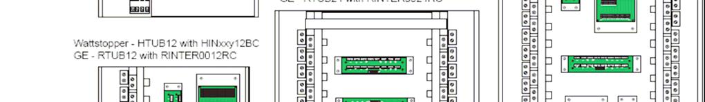

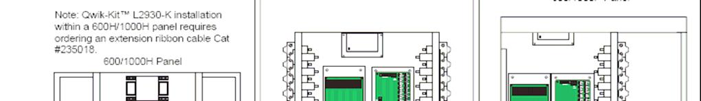
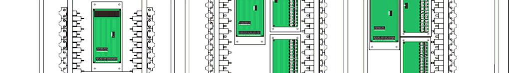
25 Appendix A (Cont): APK-kit Compatible Panels and Mounting Configurations 25
26 Appendix A (Cont): APK-kit Compatible Panels and Mounting Configurations 26
Obsolete. BR Series USB Tech Kit. B l u e R i d g e. T e c h n o l o g i e s. User Guide. Page 1. Hardware and Software Instructions
 Hardware and Software Instructions Page 1 Attention Page 2 This section serves as a notice of the immediate or potential dangers involved when working with the equipment described throughout this manual.
MAXIOM. Data Sheet. Lighting Relay Panel. Overview Leverage the Power of BAS Integration
 Data Sheet Lighting Relay Panel Overview Leverage the Power of BAS Integration Exterior with Surface Mount Trim The Series UL Listed, Lighting Control Panel provides the capability to control high voltage
Introduction. What is the UC Open controller? Specifications
 UC Open CARRIER CORPORATION 2017 A member of the United Technologies Corporation family Stock symbol UTX Catalog No. 11-808-464-01 2/24/2017 Verify that you have the most current version of this document
and Network Interface Modules Installation Instructions
 4010-9817 and 4010-9821 Network Interface Modules Installation Instructions Cautions and Warnings DO NOT INSTALL ANY SIMPLEX PRODUCT THAT APPEARS DAMAGED. Upon unpacking your Simplex product, inspect the
Quick Start Installation Guide
 apc/l Quick Start Installation Guide Version A2 Document Part Number UM-201 May 2010 OVERVIEW The apc/l is an intelligent access control and alarm monitoring control panel which serves as a basic building
Instruction Bulletin
 Instruction Bulletin 63249-401-200/A4 03/2005 POWERLINK TM G3 Controller NF1000G3 for use with POWERLINK G3 Systems Retain for future use. NOTICE Read these instructions carefully and look at the equipment
ControlKeeper 4. General Information. Connecting Relay Loads. Installation Sheet. Getting Started. Power Supply Wiring. Mounting the Cabinet
 General Information ControlKeeper 4 Installation Sheet Model# CK4-120NO- Model# CK4-277NO The ControlKeeper-4 model is shipped in one package and is configured with either a 120V or a 277V transformer.
MicroTech III Applied Terminal Systems BACnet MS/TP Communication Module
 Installation and Maintenance Manual IM 928-2 Group: Controls Part Number: 669207702 Date: March 2011 Supersedes: IM 928-1 MicroTech III Applied Terminal Systems BACnet MS/TP Communication Module NOTICE
Rev Cutler-Hammer Smart Breaker Panel Control Manual
 026-70 Rev 0 6-0-03 Cutler-Hammer Smart Breaker Panel Control Manual 640 Airport Road, Suite 04 Kennesaw, GA 3044 Phone: (770) 425-2724 Fax: (770) 425-939 ALL RIGHTS RESERVED. The information contained
MX200 SERIES Modbus Card 50P GE Zenith Controls. Operation and Maintenance Manual 50R-2200B 12/00
 g MX200 SERIES Modbus Card 50P-1105 GE Zenith Controls 50R-2200B 12/00 Operation and Maintenance Manual Table of Contents Overview...01 Page LED Indicator...02 Installation...03 Installing the Network
PS/IO Circuit Board Retrofit
 S&C 6800 Series Automatic Switch Controls PS/IO Circuit Board Retrofit Table of Contents Section Page Introduction Qualified Persons.... 2 Read this Instruction Sheet.... 2 Retain this Instruction Sheet....
Installation & Operation Guide
 Installation & Operation Guide (Shown with optional Override Board Cover) KMD-5831 Programmable Loop Controller PLC-28 Direct Digital Controller 902-019-04B 1 Introduction This section provides a brief
INSTALLATION INSTRUCTIONS
 INSTALLATION INSTRUCTIONS BACnet Communication Card RXRX-AY01 RECOGNIZE THIS SYMBOL AS AN INDICATION OF IMPORTANT SAFETY INFORMATION! WARNING THESE INSTRUCTIONS ARE INTENDED AS AN AID TO QUALIFIED, LICENSED
READ AND FOLLOW ALL SAFETY INSTRUCTIONS! SAVE THESE INSTRUCTIONS AND DELIVER TO OWNER AFTER INSTALLATION IMPORTANT SAFETY INSTRUCTIONS
 LRC0 8X0A Relay Control Panel BACnet MS/TP Enabled INSTALLATI INSTRUCTIS READ AND FOLLOW ALL SAFETY INSTRUCTIS! SAVE THESE INSTRUCTIS AND DELIVER TO OWNER AFTER INSTALLATI IMPORTANT SAFETY INSTRUCTIS!
EX-RC1 Remote I/O Adapter
 EX-RC1 Remote I/O Adapter The EX-RC1 interfaces between Unitronics Vision OPLCs and remote I/O Expansion Modules distributed throughout your system. The adapter is connected to a PLC via CANbus. Each adapter
MicroTech Modem Kit. Installation & Maintenance Data IM 682. Group: Controls Part Number: Date: October, 1996.
 Installation & Maintenance Data IM 682 Group: Controls Part Number: 629976 Date: October, 1996 MicroTech Modem Kit Telephone Line Modem Controller cns no. a0006 1996 McQuay International Contents Contents...2
MicroTech III Water Source Heat Pump BACnet MS/TP Communication Module
 Installation and Maintenance Manual IM 928- Group: Controls Part Number: 66920770 Date: July 2009 Supersedes: IM 928 MicroTech III Water Source Heat Pump BACnet MS/TP Communication Module NOTICE Use this
MicroTech Series-100 Application Specific Controller
 Installation & Maintenance Data IM 657-1 Group: Controls Part Number: 594861Y Date: March 1998 MicroTech Series-100 Application Specific Controller a0196 1998 McQuay International Contents Contents...2
6222 Two Door Module Technical Operations Manual
 6222 Two Door Module Technical Operations Manual TABLE OF CONTENTS Specifications...3 Overview...4 Operations...5 Custom Access Mode...5 Standard Access Mode...5 Offline Access Mode...5 Offline Memory...5
EX-RC1 Remote I/O Adapter
 EX-RC1 Remote I/O Adapter The EX-RC1 interfaces between Unitronics Vision OPLCs and remote I/O Expansion Modules distributed throughout your system. The adapter is connected to a PLC via CANbus. Each adapter
4100/4120-Series and 4010ES Relay Modules Installation Instructions
 4100/4120-Series and 4010ES Relay Modules Installation Instructions Introduction This publication describes the installation procedure for the relay cards listed in the following table. Model Number Description
UniStream CPU-for-Panel
 UniStream CPU-for-Panel Installation Guide USC-P-B10 Unitronics UniStream platform comprises control devices that provide robust, flexible solutions for industrial automation. This guide provides basic
SAVE THESE INSTRUCTIONS
 READ AND FOLLOW ALL SAFETY INSTRUCTIS! SAVE THESE INSTRUCTIS AND DELIVER TO OWNER AFTER INSTALLATI IMPORTANT SAFETY INSTRUCTIS WARNING To reduce the risk of death, injury or property damage from fire,
QUICK START. Installation & Programming Guide
 QUICK START Installation & Programming Guide PRECAUTIONS READ AND FOLLOW ALL SAFETY INSTRUCTIONS. CAUTION - RISK OF ELECTRICAL SHOCK. To prevent electrical shock, turn off power at the circuit breaker
2002 Series DeviceNet Technical Manual
 2002 Series DeviceNet Technical Manual Table of Contents 2002 Series DeviceNet Technical Manual 2002 Introduction...4 Product Overview...4 About DeviceNet...5 Overview...5 2002 DeviceNet Features...5 Cabling
4100/ VDC Converter Installation Instructions
 4100/4120-0156 8 VDC Converter Installation Instructions Introduction This publication describes the installation procedure for the 8 VDC Converter. Related Documentation Field Wiring Diagram for 4100
4100/4120-Series Class A / Class B Zone Modules Installation Instructions
 4100/4120-Series Class A / Class B Zone Modules Installation Instructions Introduction This publication describes the installation procedure for the following modules. Model Description Required Back Box
USER GUIDE. Stand-Alone Version
 USER GUIDE Version 2D-SA 1/1/06 Stand-Alone Version Class A FCC Device Statement Warning: Changes or modifications to this unit not expressly approved by the party responsible for compliance could void
SmartLock Controller INSTALLATION MANUAL
 SmartLock Controller INSTALLATI MANUAL November 2015 Table of Contents INTRODUCTI... 3 Diodes... 4 Terminal Strips and Cable... 5 SPECIFICATIS... 6 SMARTLOCK CTROLLER LAYOUT... 8 LED Indicators... 9 Mounting...
Copy Machine Reader. Installation and Setup Guide
 Copy Machine Reader Installation and Setup Guide CONTENTS 1 COPY MACHINE READER INSTALLATION 1 Overview 1 Reader Specifications 3 CR1120/CR1122 INSTALLATION 3 Copier Interface 3 AC Electrical 3 Communications
10/100/1000T to Mini-GBIC Industrial Switch Converter 10/100/1000T to 1000SX/LX Industrial Switch Converter. AMG9011G-H (-40 to 75C) User Manual
 User Manual") 10/100/1000T to Mini-GBIC Industrial Switch Converter 10/100/1000T to 1000SX/LX Industrial Switch Converter AMG9011G-H (-40 to 75C) User Manual www.amgsystems.com Content Overview...1 Introduction... 1
10/100/1000T to Mini-GBIC Industrial Switch Converter 10/100/1000T to 1000SX/LX Industrial Switch Converter AMG9011G-H (-40 to 75C) User Manual www.amgsystems.com Content Overview...1 Introduction... 1
TRC-190 User s Manual
 First Edition, November 2008 www.moxa.com/product 2008 Moxa Inc. All rights reserved. Reproduction without permission is prohibited. The software described in this manual is furnished under a license agreement
3710 ACM 3750 PDC 3800 RTU. ISOCOM Communications Card Retrofit Instructions
 3710 ACM 3750 PDC 3800 RTU ISOCOM Communications Card Retrofit Instructions Danger During normal operation of this device, hazardous voltages are present which can cause severe injury or death. These
Vision OPLC. General Description. Standard Kit Contents. Installation Guide Vision120. This guide provides basic information for Unitronics Vision120.
 Vision OPLC Installation Guide Vision120 This guide provides basic information for Unitronics Vision120. General Description V120 OPLCs are micro-oplcs, rugged programmable logic controllers that comprise
LITETOUCH HYBRID WALL BOX DIMMER INSTALLATION INSTRUCTIONS
 READ INSTRUCTIONS PRIOR TO INSTALLATION OF EQUIPMENT OR YOU MAY VOID THE WARRANTY! LITETOUCH INSTALLATION INSTRUCTIONS The LiteTouch Hybrid Wall Box Dimmer is a configurable lighting control device, that
Trademark Generation II Series Intercom System Installation and Operation Reference Guide
 Trademark Generation II Series Intercom System Installation and Operation Reference Guide www.escoservices.com Components: Desktop Controller, Digital Interface Box, -Speaker I/O Card, 9VDC Power Supply
H704-42(H)(E), H704-42/1(H)(E)
(E), H704-42/1(H)(E)") POWER MONITORING INSTALLATION GUIDE H704-42(H)(E), H704-42/1(H)(E) Branch Current Monitor DANGER NOTICE Installer's Specifications General: Operating Temp. Range 0 to 60 C (32 to 140 F) (
POWER MONITORING INSTALLATION GUIDE H704-42(H)(E), H704-42/1(H)(E) Branch Current Monitor DANGER NOTICE Installer's Specifications General: Operating Temp. Range 0 to 60 C (32 to 140 F) (
What are the MPC Open XP and MPC Open XPIO expanders?
 IO48/816 CARRIER CORPORATION 2017 A member of the United Technologies Corporation family Stock symbol UTX Catalog No. 11-808-431-01 6/20/2017 Verify that you have the most current version of this document
USP-070-B08 USP-104-B10, USP-104-M10 USP-156-B10
 UniStream HMI Panel Installation Guide USP-070-B10, USP-070-B08 USP-104-B10, USP-104-M10 USP-156-B10 Unitronics UniStream platform comprises control devices that provide robust, flexible solutions for
Clipsal Bus Couplers. Two Channel (SLC5102BCLEDL) and Four Channel (SLC5104BCL) for Use with C-Bus Wired Systems
 and Four Channel (SLC5104BCL) for Use with C-Bus Wired Systems") Clipsal Bus Couplers Two Channel (SLC5102BCLEDL) and Four Channel (SLC5104BCL) for Use with C-Bus Wired Systems Instruction Bulletin Retain for future use. Clipsal Bus Couplers 63249-420-236A2 Instruction
Clipsal Bus Couplers Two Channel (SLC5102BCLEDL) and Four Channel (SLC5104BCL) for Use with C-Bus Wired Systems Instruction Bulletin Retain for future use. Clipsal Bus Couplers 63249-420-236A2 Instruction
Wireless Fixture Adapter (WFA100-SN) Installation Instructions
 Installation Instructions") Installation Instructions The Daintree Wireless Fiture Adapter () forms part of Daintree s Controlscope Manager (CSM) in commercial and industrial buildings. It transmits and receives messages over the
Installation Instructions The Daintree Wireless Fiture Adapter () forms part of Daintree s Controlscope Manager (CSM) in commercial and industrial buildings. It transmits and receives messages over the
Figure 1. 6-Way JAMMA Switcher
 RiddledTV.com 6-Way, Single-Board JAMMA Switcher INSTALLATION GUIDE Figure 1. 6-Way JAMMA Switcher Features: Supports 6 JAMMA boards Only 1 JAMMA board is powered at a time. No external remotes required
INSTALLATION INSTRUCTIONS
 TT-40 9/0 INSTALLATION INSTRUCTIONS Original Issue Date: 9/0 Model: Automatic Transfer Switches Equipped with the Programmable Controller Market: ATS Subject: External Battery Supply Module Kit GM69-KP
CDN502 HIGH DENSITY I/O ADAPTER USER GUIDE
 CDN502 HIGH DENSITY I/O ADAPTER USER GUIDE 13050201 (c) Copyright DIP Inc., 1996 DIP Inc. P.O. Box 9550 MORENO VALLEY, CA 92303 714-924-1730 CONTENTS DN502 PRODUCT OVERVIEW 1 DN502 INSTALLATION 1 POWER
TRC-190 User s Manual
 User s Manual Edition 3.2, May 2017 www.moxa.com/product 2017 Moxa Inc. All rights reserved. User s Manual The software described in this manual is furnished under a license agreement and may be used only
KWIC (Kysor-Warren Interface Control) Installation and Operations Manual
 Installation and Operations Manual") .U4 #2 C36 R38 R39 S/N U3 D37 RN33 U39 Q3 Y3 RN3. D36 R32 R3 C39 U39 Form No. 44644 Release: Rev. E Date: May 28, 999 Supersedes: Rev. D KWIC (Kysor-Warren Interface Control) Installation and Operations
.U4 #2 C36 R38 R39 S/N U3 D37 RN33 U39 Q3 Y3 RN3. D36 R32 R3 C39 U39 Form No. 44644 Release: Rev. E Date: May 28, 999 Supersedes: Rev. D KWIC (Kysor-Warren Interface Control) Installation and Operations
NCH-1000 (Multiple Breaker Types) Installation Instructions
 Installation Instructions") 20M1 12345678 NCH-1000 (Multiple Breaker Types) Installation Instructions DOC. #560502100 C 7/30/04 PRINTED IN U.S.A. Regulatory Compliance Safety This device has been tested and found to be in compliance
20M1 12345678 NCH-1000 (Multiple Breaker Types) Installation Instructions DOC. #560502100 C 7/30/04 PRINTED IN U.S.A. Regulatory Compliance Safety This device has been tested and found to be in compliance
4.7 Expansion Module MAC00-FS1/FS4
 MAC00-FS4 With M12 connectors MAC00-FS1 With D sub connectors TT1068GB 4.7.1 High speed serial RS485 module MAC00-FS1 and FS4 Introduction The MAC00-FS1 and FS4 are used for high speed RS485 communication
Hypercable injecteur HPOE - Industrial IEEE 802.3at Gigabit PoE Injector. User Manual. v.1.0 Jun Mail :
 Industrial IEEE 802.3at Gigabit PoE Injector User Manual v.1.0 Jun-2011 FCC Warning This Equipment has been tested and found to comply with the limits for a Class A digital device, pursuant to Part 15
The identified danger could cause physical and property damage.
 Samba OPLC SM35-J-T20 Installation Guide The Unitronics SM35-J-T20 offers the following onboard I/Os: 12 Digital Inputs, configurable via wiring to include 2 Analog and 3 HSC/Shaft-encoder Inputs 8 Transistor
ILC LightLEEDer MicroLite 1000P Retrofit Installation
 ILC LightLEEDer MicroLite 1000P Retrofit Installation Congratulations on the purchase of your new ILC LightLEEDer Retrofit System. The ILC LightLEEDer MicroLite Retrofit System is designed for the replacement
Suprex RS-485 SPX-7500 Wired Reader-Extender
 Suprex RS-485 SPX-7500 Wired Reader-Extender Product Manual SPX-7500_MAN_181206 Cypress Integration Solutions 35 Years of Access Control Ingenuity CypressIntegration.com 2018 Cypress Computer Systems 1778
Raven Adapter Harness
 Note: Indented items indicate parts included in an assembly listed above Quantity by System Part Name/Description Part Number With Switch Box With Built-in Switches Raven Harness Adapter Kit 4100504 1
4170 POS System Installation Guide
 4170 POS System 4170 Installation Guide Thank you for selecting UTC RETAIL s innovative Model 4170 Point of Sale solution! This Installation Guide will help you efficiently install the 4170 POS. The document
EX-RC1 Remote I/O Adapter
 EX-RC1 Remote I/O Adapter The EX-RC1 interfaces between Unitronics Vision OPLCs and remote I/O Expansion Modules distributed throughout your system. The adapter is connected to a PLC via CANbus. Each adapter
QRPometer Assembly Manual Copyright 2012 David Cripe NM0S The 4 State QRP Group. Introduction
 QRPometer Assembly Manual Copyright 2012 David Cripe NM0S The 4 State QRP Group Introduction Thank you for purchasing a QRPometer. We hope you will enjoy building it and and find it a useful addition to
INSTALLATION INSTRUCTIONS
 TM REPLACEMENT PARTS FOR USE WITH CX SERIES PANELS INSTALLATION INSTRUCTIONS Hubbell Control Solutions 9601 Dessau Road Building One Suite 100 Austin, TX 78754 Toll Free: 888-698-3242 Fax: 512-450-1215
KTD-125/ KTD-125P/125P-24 KTD-127/127W PTZ Receivers
 KTD-125/125-24 KTD-125P/125P-24 KTD-127/127W PTZ Receivers 2003 Kalatel, a GE Interlogix company All Rights Reserved. Any GE Interlogix, Kalatel division, software supplied with GE Interlogix, Kalatel
Single cable kit for the FCB1010
 Single cable kit for the FCB1010 1. What is it? With this kit, you can turn your FCB1010 into a phantom powered floorboard, which can do 2-way MIDI communication over one single cable. After installing
VCM Systems Vehicle Control Module Systems
 VCM Systems Vehicle Control Module Systems Technical Manual VCMS-SC (Standard Configuration) Switch Panel System The Model VCMS-SC Switch Panel System is a standard configuration of the VCMS product family
RMB Peripheral Units Installation Guide
 RMB Peripheral Units Installation Guide Part Number 65-000101 2011 by Kentrox, Inc. All rights reserved. Copyright 2011 by Kentrox, Inc. All Rights Reserved. The material discussed in this publication
Security and Convenience Components 519H Three-Channel Receiver
 Security and Convenience Components 519H Three-Channel Receiver FCC/ID Notice This device complies with Part 15 of FCC rules. Operation is subject to the following two conditions: (1) This device may not
AppController overview and specifications
 AppController CARRIER CORPORATION 2018 A member of the United Technologies Corporation family Stock symbol UTX Catalog No. 11-808-477-01 2/28/2018 Verify that you have the most current version of this
What are the MPC Open XP and MPC Open XPIO expanders?
 IO48/816 CARRIER CORPORATION 2018 A member of the United Technologies Corporation family Stock symbol UTX Catalog No. 11-808-431-01 10/29/2018 Verify that you have the most current version of this document
INSTALLATION INSTRUCTIONS FOR THE MINI-KEY SYSTEM. Doc Rev B
 INSTALLATION INSTRUCTIONS FOR THE MINI-KEY SYSTEM Doc. 6001051 Rev B Page 2 of 7 Doc 6001051 Rev B IMPORTANT NOTICES The Mini-Key system is a very reliable and easy to use system. However, damage could
UniStream HMI Panel. CPU-for-Panel
 UniStream HMI Panel Installation Guide USP-070-B10,USP-104-B10, USP-156-B10 Unitronics UniStream platform comprises control devices that provide robust, flexible solutions for industrial automation. This
OPLC Installation Guide
 Samba OPLC SM35-J-R20/SM43-J-R20 SM70-J-R20 SM35-J-T20/SM43-J-T20 SM70-J-T20 OPLC Installation Guide 12 Digital Inputs, include 1 HSC/Shaft-encoder Input, 2 Analog inputs (only when the digital inputs
DLA. DMX512 Analyzer. DLA Users Manual SV2_00 B.lwp copyright ELM Video Technology, Inc.
 DLA DMX512 Analyzer DLA DLA-HH 1 Table Of Contents IMPORTANT SAFEGUARDS... 2 DLA OVERVIEW... 3 CONNECTION... 3 OPERATION... 3 HARDWARE SETUP... 4 DLA-HH (PORTABLE) LAYOUT... 4 CHASSIS LAYOUT... 4 DLA MENU
When any of the following symbols appear, read the associated information carefully. Symbol Meaning Description
 Vision OPLC V350-35-R34/V350-J-R34 Installation Guide The Unitronics V350-35-R34/V350-J-R34 offers the following onboard I/Os: 22 Digital Inputs, configurable via wiring to include 2 Analog and 3 HSC/Shaft-encoder
Vision OPLC V TR6/V350-J-TR6
 Vision OPLC V350-35-TR6/V350-J-TR6 Installation Guide The Unitronics V350-35-TR6/V350-J-TR6 offers the following onboard I/Os: 8 Digital Inputs, configurable via wiring to include 2 Analog (current/voltage)
Component identification
 IO-ATC8 I/O Expansion Module 8 Analog/Thermocouple Inputs The IO-ATC8 is an I/O Expansion Module that can be used in conjunction with specific Unitronics OPLC controllers. The module offers 8 inputs that
UNT1100 Series. Binary Output Jumpers AO2 AO1 AO3 AO4 AOCM AOCM AOCM AOCM AO1. AI Switches Job Information N2 Address. Ref N2+ N2- ADDR 0 = ALL OPEN
 1 2 8 4 AI6 R R Installation Bulletin UNT1100 Issue Date 0309 UNT1100 Series Introduction The Unitary (UNT) controller (UNT1100 Series) is a digital controller with applications for air handling units,
MC 11 EB-2 Power supply cabinet with external bus, AC version
 MC 11 EB-2 Power supply cabinet with external bus, AC version USER/MAINTENANCE MANUAL 1 SLOT 0 SLOT 1 SLOT 2 SLOT 3 SLOT 4 SLOT 5 SLOT 6 SLOT 7 SLOT 8 SLOT 9 SLOT 10 SLOT 11 EB-2 (a) MC11 (b) (c) Figures
When any of the following symbols appear, read the associated information carefully. Symbol Meaning Description
 Vision OPLC V130 COM Modules: V100-17-CAN, V100-17-RS4/X, V100-17-ET2 This guide shows you how to install an additional communication module in a V130 controller. Instructions and technical specifications
Network Controller. Installation/Troubleshooting Instructions NK220 COM1131C
 Network Controller NK220 COM1131C Installation/Troubleshooting Instructions Part No. 70399101R4 October 2009 Table of Contents Getting Started... 2 Components of Network Controller... 2 System Overview...
CDN503 HIGH DENSITY I/O ADAPTER USER GUIDE
 CDN503 HIGH DENSITY I/O ADAPTER USER GUIDE 13050301 (c) Copyright DIP Inc., 1996 DIP Inc. P.O. Box 9550 MORENO VALLEY, CA 92303 714-924-1730 CONTENTS DN503 PRODUCT OVERVIEW 1 DN503 INSTALLATION 1 POWER
AppController overview and specifications
 AppController CARRIER CORPORATION 2018 A member of the United Technologies Corporation family Stock symbol UTX Catalog No. 11-808-477-01 10/25/2018 Verify that you have the most current version of this
When any of the following symbols appear, read the associated information carefully. Symbol Meaning Description
 Uni-I/O Modules Installation Guide UIA-0402N Uni-I/O is a family of Input/Output modules that are compatible with the UniStream control platform. This guide provides basic installation information for
ME930C-RJ11 MAIN MODULE (FRONT CARD) MAIN MODULE. Line: RJ-11 INTERFACE MODULE (REAR CARD) Serial: DB25 CONN. SW1 RJ-11 CONN.
 MAIN MODULE. Line: RJ-11 INTERFACE MODULE (REAR CARD) Serial: DB25 CONN. SW1 RJ-11 CONN.") ME930C-RJ11 Line: RJ-11 ME930C-RJ11 MAIN MODULE Power -TD -RD INTERFACE MODULE (REAR CARD) TEST -Cntrl In -Cntrl Out Serial: DB25 CN. 7 8 SW1 JB2 1 2 3 RJ-11 CN. JB3 INTERFACE MODULE (REAR CARD) 1 2 3
ME930C-RJ11 Line: RJ-11 ME930C-RJ11 MAIN MODULE Power -TD -RD INTERFACE MODULE (REAR CARD) TEST -Cntrl In -Cntrl Out Serial: DB25 CN. 7 8 SW1 JB2 1 2 3 RJ-11 CN. JB3 INTERFACE MODULE (REAR CARD) 1 2 3
Principal LED Qwik Stik Fluorescent Bulb Replacements
 Principal LED Qwik Stik Fluorescent Bulb Replacements LED Retrofit Guide (PL-RT1-001) WARNING Installation must only be performed by a licensed electrician. To prevent death, injury or damage to property
Expansion Unit Catalog Nos , - 152, - 153, - 154, - 156, -E157
 PRODUCT DA TA SLC 150 110 Expansion Unit Catalog Nos. 1745-151, - 152, - 153, - 154, - 156, -E157 7 : The EXpdnSiQn Unit The SLC 150 expansion unit can be used with either the SLC 150 processor unit or
INSTALLATION INSTRUCTIONS
 LIGHTING CONTROL PANELS 16 AND 24 RELAYS INSTALLATION INSTRUCTIONS INSTALLATION OVERVIEW The installation instructions contained in this document are provided as a guide for proper and reliable installation.
4.8 Expansion Module MAC00-FS1/FS4
 .8 Expansion Module MAC00-FS/FS MAC00-FS With M connectors MAC00-FS With D sub connectors TT08GB.8. High speed serial RS8 module MAC00-FS and FS Introduction The MAC00-FS and FS are used for high speed
User Guide CPSMP VAC Power Supply Module: PointSystem CPSMC Accessory CPSMC Accessory. Contents.
 User Guide CPSMP-205 110 240 VAC Power Supply Module: PointSystem CPSMC1800-200 Accessory CPSMC1900-100 Accessory Contents Contents...1 Description...1 Cautions and Warnings...2 Definitions...2 Power supply
Advanced Distribution Cable Junction Box For Spectra RMS Molded-Case Circuit Breakers with Advanced Feature microentelliguard TM Trip Units
 GE Energy Industrial Solutions GEH-704 Installation Instructions Advanced Distribution Cable Junction Box For Spectra RMS Molded-Case Circuit Breakers with Advanced Feature microentelliguard TM Trip Units
Failure to comply with appropriate safety guidelines can cause severe injury or property damage.
 Vision OPLC V350-35-B1/V350-J-B1 Installation Guide The Unitronics V350-35-B1/V350-J-B1 offers the following features: I/O configurations can be added via Expansion Modules. General Description V350 OPLCs
UC-2000 Installation Manual Unicorn Computers Technology Limited
 UC2000 Installation Manual Copyright 2003. All rights reserved. Table of Contents Specifications 2 Enclosure for the UC2000 Controller 3 Unicorn Access Control System Configuration 4 UC2000 Controller
ZN551 Control Module. Technical Instructions
 ZN551 Control Module Technical Instructions What is the ZN551 control module?... 2 Module driver and control program... 2 Specifications... 2 Inputs... 3 Room sensors... 3 Digital outputs... 3 Analog outputs...
Vorne Industries. 2000S Series Serial Input Alphanumeric Display User's Manual
 Vorne Industries 2000S Series Serial Input Alphanumeric Display User's Manual 1445 Industrial Drive Itasca, IL 60143-1849 Telephone (630) 875-3600 Telefax (630) 875-3609 2000S Series Serial Input Alphanumeric
TCNM-ACBB1 Installation Manual
 The TCNM-ACBB1 is a connection box that can be used as an accessory to facilitate system connections for installation and device replacement of several Banner family reading devices. System cabling is
Model# CKM18 Model# CKM36 Model# CKM48 WARNING
 Installation Instructions Model# CKM18 Model# CKM36 Model# CKM48 WARNING HAZARDOUS VOLTAGES. DISCONNECT FROM SUPPLY BEFORE REMOVING COVERS. NO USER SERVICEABLE PARTS INSIDE. SERVICE BY QUALIFIED PERSONNEL
SAVE THESE INSTRUCTIONS
 READ AND FOLLOW ALL SAFETY INSTRUCTIS! SAVE THESE INSTRUCTIS AND DELIVER TO OWNER AFTER INSTALLATI IMPORTANT SAFETY INSTRUCTIS WARNING To reduce the risk of death, injury or property damage from fire,
When any of the following symbols appear, read the associated information carefully. Symbol Meaning Description
 Uni-I/O Modules Installation Guide UID-0808THS Uni-I/O is a family of Input/Output modules that are compatible with the UniStream control platform. This guide provides basic installation information for
User Manual. JS-ICON 624 PACK Portable Dimmer Pack. JOHNSON SYSTEMS INC. Spring
 User Manual JS-ICON 624 PACK Portable Dimmer Pack JOHNSON SYSTEMS INC. Spring 2007 Table of Contents JS-ICON 624 DMX JS-ICON 624 CC 6-2.4kW Dimming Strip JS-ICON 624 ND 6-2.4kW Relay Strip Introduction...3
Installation Instructions
 SPECIFICATIONS Lighting Integrator DMX512 Interface Models: LID8, LID24, LID48 LIDA8, LIDA24, LIDA48 Supply Voltages...per selected power supply P115/277 Power Supply... 120 or 277VAC P240 Power Supply...240VAC
CR3000 Copy Reader. Installation Guide
 CR3000 Copy Reader Installation Guide CONTENTS CONTENTS 1 CR3000 Installation Guide 1 What you get: 2 Installation Overview 3 Install the Reader 4 Mount the Reader 4 Connect the Reader Cables 5 Connect
Basketball Shot Clock Set LX2180 Manual
 Basketball Shot Clock Set LX2180 Manual 72 Industrial Boulevard Wrightsville, GA 31096 Phone: (800) 445-7843 Fax: (800) 864-0212 www.electro-mech.com LX2180 Revision 5 February 8, 2013 Table of Contents
Acuity Relay Panel User Guide
 Acuity Relay Panel User Guide 1 of 26 Table of Contents Installation and Troubleshooting 1.1 - Powering Up the Panel... 3 1.2 - LED Blink Codes On Relay Control Card... 5 1.3 - Testing Relay and Dimming
ME778C-RJ45 MAIN MODULE (FRONT CARD) MAIN MODULE. Line: RJ-45. Line: RJ-45 INTERFACE MODULE (REAR CARD) Serial: 10-Pin RJ.
 MAIN MODULE. Line: RJ-45. Line: RJ-45 INTERFACE MODULE (REAR CARD) Serial: 10-Pin RJ.") ME778C-RJ45 Line: RJ-45 MAIN MODULE Mini Driver MP Card ME778C-RJ45 Power Line: RJ-45 Unit A -TD -RD -CD -TD Serial: 10-Pin RJ INTERFACE MODULE (REAR CARD) Unit B -RD -CD Serial: 10-Pin RJ LO Z A HI Z
ME778C-RJ45 Line: RJ-45 MAIN MODULE Mini Driver MP Card ME778C-RJ45 Power Line: RJ-45 Unit A -TD -RD -CD -TD Serial: 10-Pin RJ INTERFACE MODULE (REAR CARD) Unit B -RD -CD Serial: 10-Pin RJ LO Z A HI Z
T1K MODBUS Base Controller Specifications
 Base Controller 1 2 In This Chapter.... Base Controller Setting the DIP Switches Setting the Rotary Address Switches Port Pin out and Wiring RJ12 Serial Port Pin out and Wiring 2 2 Base Controller General