1. Introduction 2. Methods for I/O Operations 3. Buses 4. Liquid Crystal Displays 5. Other Types of Displays 6. Graphics Adapters 7.
|
|
|
- Gertrude Gillian Ford
- 5 years ago
- Views:
Transcription
1 1. Introduction 2. Methods for I/O Operations 3. Buses 4. Liquid Crystal Displays 5. Other Types of Displays 6. Graphics Adapters 7. Optical Discs 1
2 Introduction Electrical Considerations Data Transfer Synchronization Bus Arbitration VME Bus Local Buses PCI Bus PCI Bus Variants Serial Buses 2
3 Buses: electrical pathways for transmission of signals between various modules of a computer system Computer systems have several different buses: A system bus for connecting the CPU to the memory One or more I/O buses for connecting the peripheral devices to the CPU 3

4 Buses in a computer system 4
5 Dual-Bus Architectures DIB (Dual Independent Bus) The system bus is replaced with two buses: FSB and BSB FSB (Front Side Bus): between the CPU and main memory BSB (Back Side Bus): between the CPU and the level-2 (or level-3) cache memory 5
6 Certain devices connected to the bus are active and may initiate a transfer master Other devices are passive and wait for transfer requests slave Example: The CPU requests a disk controller to read or write a data block The CPU is acting as a master The controller is acting as a slave 6
7 Introduction Electrical Considerations Data Transfer Synchronization Bus Arbitration VME Bus Local Buses PCI Bus PCI Bus Variants Serial Buses 7
8 Designing high-performance buses requires to minimize several undesirable electrical phenomena Cause the decrease of systems reliability The most important: signal reflections Signal reflections are the result of impedance discontinuities: connectors, capacitive loads, device inputs, board layer changes 8
9 Signal reflections have the effect of voltage and current oscillations To eliminate signal reflections, bus termination must be used Termination: Passive (resistive) Active Resistive terminators can be connected in series or in parallel 9
10 Series termination In the ideal case: R s + Z s = Z 0 Z s source impedance Z 0 line impedance 10
11 Parallel termination A resistor is placed at the receiving end split resistor network The equivalent resistance R e should equal the line impedance Z 0 May be used for bidirectional buses 11
12 Introduction Electrical Considerations Data Transfer Synchronization Bus Arbitration VME Bus Local Buses PCI Bus PCI Bus Variants Serial Buses 12
13 Data Transfer Synchronization Synchronous Buses Asynchronous Buses 13
14 Depending on the synchronization of data transfers, buses can be divided into: Synchronous Asynchronous Operations of synchronous buses are controlled by a clock signal require an integral number of clock periods Asynchronous buses do not use a clock signal bus cycles can have any duration 14
15 Data Transfer Synchronization Synchronous Buses Asynchronous Buses 15
16 Each word is transferred during an integral number of clock cycles This duration is known to both the source and destination units synchronization Synchronization: Connecting both units to a common clock signal short distances Using separate clock signals for each unit synchronization signals must be transmitted periodically 16
17 Synchronous transfer Read 17

18 Synchronous transfer Write 18
19 The requirement that the slave unit responds in the next clock cycle can be eliminated An additional control signal ACK or WAIT is provided, controlled by the slave unit The signal is only asserted when the slave unit has completed its data transfer The master unit waits until it receives the ACK or WAIT signal wait states are inserted 19
20 Disadvantages of synchronous buses: If a transfer is completed before an integral number of cycles, the units have to wait until the end of the cycle The speed has to be chosen according to the slowest device After choosing a bus cycle, it is difficult to take advantage of future technological improvements 20
21 Data Transfer Synchronization Synchronous Buses Asynchronous Buses 21
22 An asynchronous bus eliminates the disadvantages of synchronous buses Instead of the clock signal, additional control signals are used, and a logical protocol between the units (source, destination) The protocol may be: Unidirectional the synchronization signals are generated by one of the two units Bidirectional both units generate synchronization signals 22
 (b) Destination-initiated transfer DREQ (Data")
23 Transfer through unidirectional protocol (a) Source-initiated transfer DREADY (Data Ready) (b) Destination-initiated transfer DREQ (Data Request) 23
24 The DREADY and DREQ signals can be used to: Transfer the data from the source unit to the bus Load the data from the bus by the destination unit Strobe signals Example: The source unit generates a data word asynchronously and places it in a buffer register 24

25 The DREQ signal enables the clock input of the buffer 25
26 The unidirectional protocol does not allow to verify that the transfer has been completed successfully Example: In a source-initiated transfer, the source does not have a confirmation of data reception by the destination Solution: introducing an acknowledge signal ACK bidirectional protocol 26
27 (a) Source-initiated transfer through bidirectional protocol 27

28 (b) Destination-initiated transfer through bidirectional protocol 28

29 Memory read operation using an asynchronous protocol 29
30 MSYN (Master Synchronization) SSYN (Slave Synchronization) Fully interlocked protocol (full handshake): each action is conditioned by a previous action 30
31 Introduction Electrical Considerations Data Transfer Synchronization Bus Arbitration VME Bus Local Buses PCI Bus PCI Bus Variants Serial Buses 31
32 Bus Arbitration Centralized Arbitration Decentralized Arbitration 32
33 Has the task to determine the module that will become master in case of simultaneous requests Arbitration methods Centralized: bus allocation is performed by a bus arbiter Decentralized (distributed): there is no bus arbiter 33
34 Bus Arbitration Centralized Arbitration Decentralized Arbitration 34
35 Methods for centralized arbitration: Daisy chaining of devices Independent requesting Polling Centralized arbitration in which daisy chaining of devices is used A single bus request line, BUSREQ (Bus Request) wired OR A bus grant line BUSGNT (Bus Grant) 35

36 The device physically closest to the arbiter detects the signal on the BUSGNT line 36
37 Only two control lines are required for bus arbitration Device priority is fixed given by the chaining order on the BUSGNT line To modify the default priorities, buses may have multiple priority levels For each priority level, there is a bus request line and a bus grant line 37

38 Each device attaches to one of the bus request lines, according to the device priority 38
39 Daisy chaining Advantages: Small number of control lines required The possibility to connect, theoretically, an unlimited number of devices Daisy chaining Disadvantages: Fixed priorities of the devices A high-priority device may lock out a lowpriority device Susceptibility to failures of the BUSGNT line 39
40 Centralized arbitration by independent requesting There are separate BUSREQ and BUSGNT lines for every device The arbiter may immediately identify all devices requesting the bus and may determine their priority Priority of requests is programmable Disadvantage: to control n devices, 2n BUSREQ and BUSGNT lines must be connected to the bus arbiter 40
41 Centralized arbitration by polling The BUSGNT line is replaced with a set of poll-count lines Devices request access to the bus via a common BUSREQ line The bus arbiter generates a sequence of addresses on the poll-count lines Each device compares these addresses to a unique address assigned to that device On a match, the device asserts the BUSY signal and connects to the bus 41
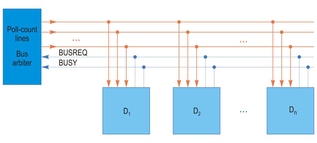
42 42
43 The priority of a device is determined by the position of its address in the polling sequence Advantage: the sequence can be programmed if the poll-count lines are connected to a programmable register Another advantage: a failure in one device does not affect other devices These advantages are achieved at the cost of more control lines 43
44 Bus Arbitration Centralized Arbitration Decentralized Arbitration 44
45 There is no bus arbiter Example of decentralized arbitration n prioritized bus request lines n devices To use the bus, a device asserts its request line All devices monitor all the request lines Disadvantages: more bus lines required; the number of devices is limited 45
46 Example of decentralized arbitration with only three lines BUSREQ wired OR BUSY asserted by the bus master Bus arbitration daisy chained The method is similar to the daisy-chain arbitration, but without an arbiter Advantages: lower cost; higher speed; not subject to arbiter failure 46
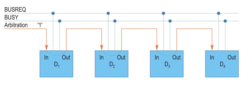
47 47
48 Introduction Electrical Considerations Data Transfer Synchronization Bus Arbitration VME Bus Local Buses PCI Bus PCI Bus Variants Serial Buses 48
49 VME Bus Overview Parallel VME Bus Variants Modules and Connectors VXS Bus Serial VME Bus 49
50 VME (Versa Module Eurocard) Originates from VERSAbus (Motorola) VERSAbus has been adapted for the double Eurocard form factor (6U, mm) VMEbus, rev. A The VME specifications have been updated (revisions B, C, C.1) IEC, IEEE, and ANSI/VITA standards (VITA - VME International Trade Association, 50
51 Asynchronous bus Allows various components to operate at a speed appropriate to the technology used Used for industrial applications and embedded systems There are no license fees The reliability of the bus is ensured by: Mechanical design connectors with metallic pins Logical protocol 51
52 Applications: Industrial control Military: radars, communications, avionics Aerospace Railway transportation Telecommunications: cellular telephone base stations, telephone switches Medical: nuclear magnetic resonance imaging Various: high-energy physics, nuclear physics 52
53 Family of three buses VME: main bus VSB: secondary bus Bus for memory extension Allows to increase performance by reducing the overall traffic on the main VME bus VMS: serial bus Used for communication and synchronization between multiple processors 53

54 (a) Minimal system; (b) Multiprocessor system 54
55 VME Bus Overview Parallel VME Bus Variants Modules and Connectors VXS Bus Serial VME Bus 55
56 Original VME Bus Non-multiplexed data and address lines Data size: bits Address size: bits Multiprocessing capability: M/S architecture Centralized arbitration by daisy-chaining A number of 7 interrupt request lines Connectors with 96 pins (3 rows x 32) Up to 21 expansion boards in a backplane 56
57 VME64 Bus 64-bit data (double Eurocard) 64-bit addresses (double Eurocard) 32-bit or 40-bit addresses (single Eurocard) Lower-noise connectors Plug and Play features ROM memory VME64x Bus 3.3 V power supply pins 141 user-defined I/O pins 57
58 New connectors with 160 pins (5 rows x 32) Compatible with the 96-pin connectors Additional connector with 95 pins (5 x 19) Higher bandwidth (up to 160 MB/s) Modified protocol for data transfer cycles 2eVME (Double-edge VME) The possibility for insertion of modules during operation (live-insertion) Front panels with guiding pins 58
59 VME320 Bus Bandwidths of over 320 MB/s (peak bandwidths of over 500 MB/s) Star-interconnection method All of the interconnections are joined together at the middle slot of the backplane A new protocol 2eSST (Double-edge Source Synchronous Transfer) During the data phases, it is a sourcesynchronous protocol 59
60 VME Bus Overview Parallel VME Bus Variants Modules and Connectors VXS Bus Serial VME Bus 60
61 VME module sizes Single-height: 3U x 160 mm (U unit of measure; 1U = 1.75 inches = mm) Double-height: 6U x 160 mm Triple-height: 9U x 400 mm Conduction cooled modules Used in military and aerospace applications Heat is conducted through the printed circuit board or through a conduction plate 61
62 VME backplanes Length of 19 inches; connectors Standard: 3-row connectors VME64x: 5-row connectors VME320 VME connector types P (Plug): reside on the modules (boards) J (Jack): reside on the backplane P1/J1, P2/J2: 96 or 160 pins 62

63 P3/J3: P3 connectors may be included on 9U modules P0/J0: 95 pins; may be used for high-speed signals Custom connectors can be placed between the P1/J1 and P2/J2 connectors, e.g., for: Coaxial cables Fiber-optic cables 63
64 VME Bus Overview Parallel VME Bus Variants Modules and Connectors VXS Bus Serial VME Bus 64
65 VXS VMEbus Switched Serial ANSI/VITA standard to combine the parallel VME bus with high-speed switched serial interconnects ANSI/VITA 41.0: Base specification ANSI/VITA 41.1: InfiniBand connector ANSI/VITA 41.2: Serial RapidIO connector ANSI/VITA 41.3: Gigabit Ethernet connector ANSI/VITA 41.4: PCI Express connector (4x) 65
66 Switched serial interconnect Point-to-point connections between modules Switch boards (1-2): contain an active switch Regular (payload) boards (up to 18): other boards that connect to the switch boards Clock and data signals are combined into a single serial bitstream Data rates of or 6.25 Gbits/s With 8b/10b encoding: or 625 MB/s With 64b/66b encoding: 378 or 756 MB/s 66
 MultiGig RT connectors A1 K1, A2 K2: alignment and keying connectors PWR1: power connector Can access VME resources")
67 Switch boards 6U x 160 mm Replace the parallel P1 and P2 connectors with 5 serial connectors (P1.. P5) MultiGig RT connectors A1 K1, A2 K2: alignment and keying connectors PWR1: power connector Can access VME resources via serial-to-vme bridges 67

68 Payload boards P1, P2: VME64x parallel connectors; 5 rows P0: high-speed serial connector; 7 rows A0 K0: alignment and keying connector The P0 connector provides eight full-duplex serial links (up to 2.5 GB/s or 5 GB/s in each direction) 68
69 VXS Backplanes Maximum configuration: 18 payload boards; 2 switch boards; 1 VME64x board Single star topology: each payload board connects to a single switch board Dual star topology: each payload board connects to both switch boards (redundancy) Mesh topology: each payload board is directly connected to every other board Up to 3 boards connected without a switch 69

70 VXS topologies: dual star; single star; mesh 70
71 VME Bus Overview Parallel VME Bus Variants Modules and Connectors VXS Bus Serial VME Bus 71
72 VPX Replaces the parallel VME bus with switched serial interconnects ANSI/VITA standard 46 ANSI/VITA 46.0: Base specification ANSI/VITA 46.1: VMEbus signal mapping ANSI/VITA 46.3: Serial RapidIO connector ANSI/VITA 46.4: PCI Express connector ANSI/VITA 46.6: Gigabit Ethernet connector 72
73 Maintains the 3U and 6U Eurocard form factors of the VME specifications 6U hybrid backplanes can also be used to accommodate VME64, VXS, and VPX boards MultiGig RT2 connectors are used Speeds up to 10.3 Gbits/s 3U boards: three connectors (P0.. P2) 6U boards: seven connectors (P0.. P6) Up to 160 differential I/O signals 73
74 Bus terminators must be used to eliminate or reduce signal reflections May be connected in series or in parallel Although synchronous buses have drawbacks, most buses are synchronous For asynchronous buses, bidirectional protocols are more reliable Bus arbitration methods can be centralized or decentralized Centralized arbitration methods: daisy-chaining, independent requesting, polling 74
75 The VME bus is one of the most successful interconnect technologies Mechanical, electrical, and software compatibility is ensured with all existing VME boards The parallel VME bus has been improved significantly, but it has reached its limits The VXS bus ensures the transition to highspeed serial interconnects The VPX bus uses only serial interconnects It will gradually replace the parallel VME bus 75
76 Signal reflections Series and parallel termination Synchronous buses Synchronous transfers Disadvantages of synchronous buses Asynchronous buses Source-initiated transfer, unidirectional Destination-initiated transfer, unidirectional Source-initiated transfer, bidirectional Destination-initiated transfer, bidirectional 76
77 Centralized bus arbitration Centralized arbitration by daisy-chaining Centralized arbitration by independent requesting Centralized arbitration by polling Decentralized bus arbitration Features of the VME64x bus Features of the VME320 bus Features of the VXS technology Features of the VPX technology 77
78 1. What are the disadvantages of centralized arbitration by daisy-chaining? 2. How does the centralized arbitration by polling work? 3. What are the main features of the VME320 bus? 4. What are the main features of the VXS technology? 78
Introduction Electrical Considerations Data Transfer Synchronization Bus Arbitration VME Bus Local Buses PCI Bus PCI Bus Variants Serial Buses
 Introduction Electrical Considerations Data Transfer Synchronization Bus Arbitration VME Bus Local Buses PCI Bus PCI Bus Variants Serial Buses 1 Most of the integrated I/O subsystems are connected to the
PCI-X Bus PCI Express Bus Variants for Portable Computers Variants for Industrial Systems
 PCI Bus Variants PCI-X Bus PCI Express Bus Variants for Portable Computers Variants for Industrial Systems 1 Variants for Portable Computers Mini PCI PCMCIA Standards CardBus ExpressCard 2 Specifications
MicroStandards. The VME subsystem bus Shlomo Pri-Tal SPECIAL FEATURE / Motorola Microsystems Tempe, Arizona
 SPECIAL FEATURE /.............. MicroStandards The VME subsystem bus Shlomo Pri-Tal Motorola Microsystems Tempe, Arizona In the latter part of 1984, the Technical Committee of the VME International Trade
Section 2 - Backplane Protocols Backplane Designer s Guide
 Section 2 - Backplane Protocols Backplane Designer s Guide February 2002 Revised April 2002 Backplane bus protocols determine - electrically and mechanically - how signals are dropped off or picked up
Buses. Disks PCI RDRAM RDRAM LAN. Some slides adapted from lecture by David Culler. Pentium 4 Processor. Memory Controller Hub.
 es > 100 MB/sec Pentium 4 Processor L1 and L2 caches Some slides adapted from lecture by David Culler 3.2 GB/sec Display Memory Controller Hub RDRAM RDRAM Dual Ultra ATA/100 24 Mbit/sec Disks LAN I/O Controller
Introduction to Embedded System I/O Architectures
 Introduction to Embedded System I/O Architectures 1 I/O terminology Synchronous / Iso-synchronous / Asynchronous Serial vs. Parallel Input/Output/Input-Output devices Full-duplex/ Half-duplex 2 Synchronous
Interconnection Structures. Patrick Happ Raul Queiroz Feitosa
 Interconnection Structures Patrick Happ Raul Queiroz Feitosa Objective To present key issues that affect interconnection design. Interconnection Structures 2 Outline Introduction Computer Busses Bus Types
Different network topologies
 Network Topology Network topology is the arrangement of the various elements of a communication network. It is the topological structure of a network and may be depicted physically or logically. Physical
Chapter 6. I/O issues
 Computer Architectures Chapter 6 I/O issues Tien-Fu Chen National Chung Cheng Univ Chap6 - Input / Output Issues I/O organization issue- CPU-memory bus, I/O bus width A/D multiplex Split transaction Synchronous
Outpacing VME: OpenVPX fast-tracks technologies to the front lines
 SPRING 2011 Outpacing VME: OpenVPX fast-tracks technologies to the front lines Advantages in SWaP, thermal management, and connectivity mean that OpenVPX s resultant rapid deployment is outrunning VME.
Unit 3 and Unit 4: Chapter 4 INPUT/OUTPUT ORGANIZATION
 Unit 3 and Unit 4: Chapter 4 INPUT/OUTPUT ORGANIZATION Introduction A general purpose computer should have the ability to exchange information with a wide range of devices in varying environments. Computers
 Accessing I/O Devices Interface to CPU and Memory Interface to one or more peripherals Generic Model of IO Module Interface for an IO Device: CPU checks I/O module device status I/O module returns status
CMSC 313 Lecture 26 DigSim Assignment 3 Cache Memory Virtual Memory + Cache Memory I/O Architecture
 CMSC 313 Lecture 26 DigSim Assignment 3 Cache Memory Virtual Memory + Cache Memory I/O Architecture UMBC, CMSC313, Richard Chang CMSC 313, Computer Organization & Assembly Language Programming
Alma2e PCI-to-VME Bridge: Using VME 2eSST Protocol
 Alma2e PCI-to-VME Bridge: Using VME 2eSST Protocol Serge Tissot September 25, 2002 Overview The ALMA2e is a new bus bridge designed by Thales Computers that interfaces between the PCI bus and the VMEbus.
Computer Architecture CS 355 Busses & I/O System
 Computer Architecture CS 355 Busses & I/O System Text: Computer Organization & Design, Patterson & Hennessy Chapter 6.5-6.6 Objectives: During this class the student shall learn to: Describe the two basic
C6100 Ruggedized PowerPC VME SBC
 C6100 Ruggedized PowerPC VME SBC Rugged 6U VME Single Slot SBC Conduction and Air-Cooled Versions Two Asynchronous Serial Interfaces Four 32-Bit Timers G4 MPC7457 PowerPC with AltiVec Technology @ up to
GEN-2 / GEN-1 OpenVPX BACKPLANES
 BENEFITS GEN-2 / GEN-1 VPX data/expansion plane support for Gen-2, backplanes compatible with: Serial RapidIO (SRIO) Gen-2 InfiniBand DDR PCI Express (PCIe) Gen-2 VPX data/expansion plane support for Gen-1,
SOLVING VENDOR LOCK-IN IN VME SINGLE BOARD COMPUTERS THROUGH OPEN-SOURCING OF THE PCIE-VME64X BRIDGE
 16th Int. Conf. on Accelerator and Large Experimental Control Systems ICALEPCS2017, Barcelona, Spain JACoW Publishing doi:10.18429/jacow-icalepcs2017- SOLVING VENDOR LOCK-IN IN VME SINGLE BOARD COMPUTERS
Chapter 3. Top Level View of Computer Function and Interconnection. Yonsei University
 Chapter 3 Top Level View of Computer Function and Interconnection Contents Computer Components Computer Function Interconnection Structures Bus Interconnection PCI 3-2 Program Concept Computer components
The PXI Modular Instrumentation Architecture
 The PXI Modular Instrumentation Architecture Overview The PXI (PCI extensions for Instrumentation) specification defines a rugged PC platform for measurement and automation. PXI modular instrumentation
Amphenol ABSI VME64x Datasheet
 Amphenol ABSI VME64x Backplanes Amphenol ABSI s VME64x high performance backplanes are available in both 3U & 6U form factors. All VME backplanes are compliant to VITA VME64x specifications. ABSI can customize
ECE 485/585 Microprocessor System Design
 Microprocessor System Design Lecture 15: Bus Fundamentals Zeshan Chishti Electrical and Computer Engineering Dept. Maseeh College of Engineering and Computer Science Source: Lecture based on materials
THE NEXT-GENERATION INTEROPERABILITY STANDARD
 THE NEXT-GENERATION INTEROPERABILITY STANDARD ABOUT OPEN VPX TM Open VPX TM is the next-generation interoperability standard for system-level defense and aerospace applications. It is ideal for rugged
EE108B Lecture 17 I/O Buses and Interfacing to CPU. Christos Kozyrakis Stanford University
 EE108B Lecture 17 I/O Buses and Interfacing to CPU Christos Kozyrakis Stanford University http://eeclass.stanford.edu/ee108b 1 Announcements Remaining deliverables PA2.2. today HW4 on 3/13 Lab4 on 3/19
CS152 Computer Architecture and Engineering Lecture 20: Busses and OS s Responsibilities. Recap: IO Benchmarks and I/O Devices
 CS152 Computer Architecture and Engineering Lecture 20: ses and OS s Responsibilities April 7, 1995 Dave Patterson (patterson@cs) and Shing Kong (shing.kong@eng.sun.com) Slides available on http://http.cs.berkeley.edu/~patterson
INPUT-OUTPUT ORGANIZATION
 INPUT-OUTPUT ORGANIZATION Peripheral Devices: The Input / output organization of computer depends upon the size of computer and the peripherals connected to it. The I/O Subsystem of the computer, provides
Artisan Technology Group is your source for quality new and certified-used/pre-owned equipment
 Artisan Technology Group is your source for quality new and certified-used/pre-owned equipment FAST SHIPPING AND DELIVERY TENS OF THOUSANDS OF IN-STOCK ITEMS EQUIPMENT DEMOS HUNDREDS OF MANUFACTURERS SUPPORTED
ECE 485/585 Microprocessor System Design
 Microprocessor System Design Lecture 16: PCI Bus Serial Buses Zeshan Chishti Electrical and Computer Engineering Dept. Maseeh College of Engineering and Computer Science Source: Lecture based on materials
Input/Output Introduction
 Input/Output 1 Introduction Motivation Performance metrics Processor interface issues Buses 2 Page 1 Motivation CPU Performance: 60% per year I/O system performance limited by mechanical delays (e.g.,
Introduction. Motivation Performance metrics Processor interface issues Buses
 Input/Output 1 Introduction Motivation Performance metrics Processor interface issues Buses 2 Motivation CPU Performance: 60% per year I/O system performance limited by mechanical delays (e.g., disk I/O)
AMC data sheet. PMC Module with four CAN bus Nodes ARINC825 compliant for Testing & Simulation of Avionic CAN bus Systems
 data sheet PMC Module with four bus Nodes ARINC825 compliant for Testing & Simulation of Avionic bus Systems Avionics Databus Solutions product guide General Features The PCI Mezzanine Card (PMC) can work
Chapter Four. Making Connections. Data Communications and Computer Networks: A Business User s Approach Seventh Edition
 Chapter Four Making Connections Data Communications and Computer Networks: A Business User s Approach Seventh Edition After reading this chapter, you should be able to: List the four components of all
GEN-3 OpenVPX BACKPLANES
 BENEFITS High performance 10 Gen-3 backplanes compatible with 40 Gb Ethernet (40 GBase-KR4), InfiniBand QDR (10 ), Infiniband FDR- 10 (10.3 ), and PCI Express (PCIe) Gen-3 (8 ) on OpenVPX data plane and
Chapter 8: Input and Output. Principles of Computer Architecture. Principles of Computer Architecture by M. Murdocca and V.
 8-1 Principles of Computer Architecture Miles Murdocca and Vincent Heuring 8-2 Chapter Contents 8.1 Simple Bus Architectures 8.2 Bridge-Based Bus Architectures 8.3 Communication Methodologies 8.4 Case
C900 PowerPC G4+ Rugged 3U CompactPCI SBC
 C900 PowerPC G4+ Rugged 3U CompactPCI SBC Rugged 3U CompactPCI SBC PICMG 2.0, Rev. 3.0 Compliant G4+ PowerPC 7447A/7448 Processor @ 1.1 Ghz with AltiVec Technology Marvell MV64460 Discovery TM III System
Computer Systems Organization
 The IAS (von Neumann) Machine Computer Systems Organization Input Output Equipment Stored Program concept Main memory storing programs and data ALU operating on binary data Control unit interpreting instructions
Interconnecting Components
 Interconnecting Components Need interconnections between CPU, memory, controllers Bus: shared communication channel Parallel set of wires for data and synchronization of data transfer Can become a bottleneck
A+ Guide to Hardware: Managing, Maintaining, and Troubleshooting, 5e. Chapter 1 Introducing Hardware
 : Managing, Maintaining, and Troubleshooting, 5e Chapter 1 Introducing Hardware Objectives Learn that a computer requires both hardware and software to work Learn about the many different hardware components
Introduction to Input and Output
 Introduction to Input and Output The I/O subsystem provides the mechanism for communication between the CPU and the outside world (I/O devices). Design factors: I/O device characteristics (input, output,
The D igital Digital Logic Level Chapter 3 1
 The Digital Logic Level Chapter 3 1 Gates and Boolean Algebra (1) (a) A transistor inverter. (b) A NAND gate. (c) A NOR gate. 2 Gates and Boolean Algebra (2) The symbols and functional behavior for the
INPUT/OUTPUT ORGANIZATION
 INPUT/OUTPUT ORGANIZATION Accessing I/O Devices I/O interface Input/output mechanism Memory-mapped I/O Programmed I/O Interrupts Direct Memory Access Buses Synchronous Bus Asynchronous Bus I/O in CO and
The hardware implementation of PXI/PXIe consists of a chassis, controller or computer interface, and peripheral cards.
 Introduction PCI extensions for Instrumentation or PXI is a computer based hardware and software platform for test and measurement systems. Developed in the late 1990 s as an open industry standard based
Chapter 8. A Typical collection of I/O devices. Interrupts. Processor. Cache. Memory I/O bus. I/O controller I/O I/O. Main memory.
 Chapter 8 1 A Typical collection of I/O devices Interrupts Cache I/O bus Main memory I/O controller I/O controller I/O controller Disk Disk Graphics output Network 2 1 Interfacing s and Peripherals I/O
Bus Example: Pentium II
 Peripheral Component Interconnect (PCI) Conventional PCI, often shortened to PCI, is a local computer bus for attaching hardware devices in a computer. PCI stands for Peripheral Component Interconnect
About the Presentations
 About the Presentations The presentations cover the objectives found in the opening of each chapter. All chapter objectives are listed in the beginning of each presentation. You may customize the presentations
SEMICON Solutions. Bus Structure. Created by: Duong Dang Date: 20 th Oct,2010
 SEMICON Solutions Bus Structure Created by: Duong Dang Date: 20 th Oct,2010 Introduction Buses are the simplest and most widely used interconnection networks A number of modules is connected via a single
C901 PowerPC MPC7448 3U CompactPCI SBC
 C901 PowerPC MPC7448 3U CompactPCI SBC Rugged 3U CompactPCI SBC PowerPC 7448 @ 1.4 GHz, 1.0 GHz, or 600 MHz, with AltiVec Technology 166 MHz MPX Bus Marvell MV64460 Discovery TM III System Controller One
Tsi148/Universe II Differences Application Note. Formal Status September 29, 2014
 Titl Tsi148/Universe II Differences Application Note September 29, 2014 Introduction This document outlines the differences between the Tsi148 and the Universe II (CA91C142D) VME bridge devices. It is
RACEway Interlink Modules
 RACE++ Series RACEway Interlink Modules 66-MHz RACE++ Switched Interconnect Adaptive Routing More than 2.1 GB/s Bisection Bandwidth Deterministically Low Latency Low Power, Field-Tested Design Flexible
Interfacing. Introduction. Introduction Addressing Interrupt DMA Arbitration Advanced communication architectures. Vahid, Givargis
 Interfacing Introduction Addressing Interrupt DMA Arbitration Advanced communication architectures Vahid, Givargis Introduction Embedded system functionality aspects Processing Transformation of data Implemented
INPUT/OUTPUT ORGANIZATION
 INPUT/OUTPUT ORGANIZATION Accessing I/O Devices I/O interface Input/output mechanism Memory-mapped I/O Programmed I/O Interrupts Direct Memory Access Buses Synchronous Bus Asynchronous Bus I/O in CO and
Darshan Institute of Engineering & Technology for Diploma Studies
 1. Explain different network devices in detail. Or Explain NIC (Network Interface Card) in detail. Network interface cards are add on cards as hardware cards on the motherboard. This is additional hardware
HyperTransport. Dennis Vega Ryan Rawlins
 HyperTransport Dennis Vega Ryan Rawlins What is HyperTransport (HT)? A point to point interconnect technology that links processors to other processors, coprocessors, I/O controllers, and peripheral controllers.
VMIVME-1184 Specifications
 GE Fanuc Automation VMIVME-1184 Specifications 32-bit Optically Isolated Change-of-State (COS) Input Board with Sequence-of-Events (SOE) Features: 32 channels of optically isolated digital Change-of-State
PCI and PCI Express Bus Architecture
 PCI and PCI Express Bus Architecture Computer Science & Engineering Department Arizona State University Tempe, AZ 85287 Dr. Yann-Hang Lee yhlee@asu.edu (480) 727-7507 7/23 Buses in PC-XT and PC-AT ISA
Bus System. Bus Lines. Bus Systems. Chapter 8. Common connection between the CPU, the memory, and the peripheral devices.
 Bus System Chapter 8 CSc 314 T W Bennet Mississippi College 1 CSc 314 T W Bennet Mississippi College 3 Bus Systems Common connection between the CPU, the memory, and the peripheral devices. One device
Lecture 25: Busses. A Typical Computer Organization
 S 09 L25-1 18-447 Lecture 25: Busses James C. Hoe Dept of ECE, CMU April 27, 2009 Announcements: Project 4 due this week (no late check off) HW 4 due today Handouts: Practice Final Solutions A Typical
This page intentionally left blank
 This page intentionally left blank 216 THE DIGITAL LOGIC LEVEL CHAP. 3 and in 1995, 2.1 came out. 2.2 has features for mobile computers (mostly for saving battery power). The bus runs at up to 66 MHz and
Chapter 5 Input/Output Organization. Jin-Fu Li Department of Electrical Engineering National Central University Jungli, Taiwan
 Chapter 5 Input/Output Organization Jin-Fu Li Department of Electrical Engineering National Central University Jungli, Taiwan Outline Accessing I/O Devices Interrupts Direct Memory Access Buses Interface
XE 900: Fastest EPIC board now available with Windows XPe
 XE 900: Fastest EPIC board now available with Windows XPe The XE 900 SBC is a high performance, low power, x86 workhorse for embedded applications. It is an EPIC form factor SBC with a rich family of I/O
Lecture 13. Storage, Network and Other Peripherals
 Lecture 13 Storage, Network and Other Peripherals 1 I/O Systems Processor interrupts Cache Processor & I/O Communication Memory - I/O Bus Main Memory I/O Controller I/O Controller I/O Controller Disk Disk
Embedded Tech Trends 2014 Rodger H. Hosking Pentek, Inc. VPX for Rugged, Conduction-Cooled Software Radio Virtex-7 Applications
 Embedded Tech Trends 2014 Rodger H. Hosking Pentek, Inc. VPX for Rugged, Conduction-Cooled Software Radio Virtex-7 Applications System Essentials: Rugged Software Radio Industry Standard Open Architectures
Integrity Instruments Application Notes. Release 1
 Integrity Instruments Application Notes Release 1 What is EIA/TIA/RS-485 What is EIA/TIA/RS-422 Half Duplex and Full Duplex Communication Asynchronous Communicatin Grounding EIA/TIA/RS-485/422 Shielding
PCI EXPRESS TECHNOLOGY. Jim Brewer, Dell Business and Technology Development Joe Sekel, Dell Server Architecture and Technology
 WHITE PAPER February 2004 PCI EXPRESS TECHNOLOGY Jim Brewer, Dell Business and Technology Development Joe Sekel, Dell Server Architecture and Technology Formerly known as 3GIO, PCI Express is the open
Unit 5. Memory and I/O System
 Unit 5 Memory and I/O System 1 Input/Output Organization 2 Overview Computer has ability to exchange data with other devices. Human-computer communication Computer-computer communication Computer-device
Introduction to the Personal Computer
 Introduction to the Personal Computer 2.1 Describe a computer system A computer system consists of hardware and software components. Hardware is the physical equipment such as the case, storage drives,
Type 12. VITA-Based System Platforms. VME, VME64x, VPX, VXS, VXI, and more. Backplanes. Elma Electronic
 Type 12 Backplanes ACcessories SYSTEM COMPONENTS INTEGRATION SERVICES VITA-Based System Platforms VME, VME64x, VPX, VXS, VXI, and more TEST & VALIDATION SERVICES Elma Electronic www.elma.com Elma Electronic
PXI Remote Control and System Expansion
 Have a question? Contact Us. PRODUCT FLYER PXI Remote Control and System Expansion CONTENTS PXI Remote Control and System Expansion Components of a Remotely Controlled PXI System Choosing a Remote Control
LVDS applications, testing, and performance evaluation expand.
 Stephen Kempainen, National Semiconductor Low Voltage Differential Signaling (LVDS), Part 2 LVDS applications, testing, and performance evaluation expand. Buses and Backplanes D Multi-drop D LVDS is a
MicroTCA / AMC Solutions for Real-Time Data Acquisition
 THE MAGAZINE OF RECORD FOR THE EMBEDDED COMPUTING INDUSTRY May 2013 TECHNOLOGY IN SYSTEMS MicroTCA / AMC Solutions for Real-Time Data Acquisition MicroTCA has evolved out of the world of ATCA to become
Module 5. Embedded Communications. Version 2 EE IIT, Kharagpur 1
 Module 5 Embedded Communications Version 2 EE IIT, Kharagpur 1 Lesson 24 Parallel Data Communication Version 2 EE IIT, Kharagpur 2 Instructional Objectives After going through this lesson the student would
Artisan Technology Group is your source for quality new and certified-used/pre-owned equipment
 Artisan Technology Group is your source for quality new and certified-used/pre-owned equipment FAST SHIPPING AND DELIVERY TENS OF THOUSANDS OF IN-STOCK ITEMS EQUIPMENT DEMOS HUNDREDS OF MANUFACTURERS SUPPORTED
Buses. Maurizio Palesi. Maurizio Palesi 1
 Buses Maurizio Palesi Maurizio Palesi 1 Introduction Buses are the simplest and most widely used interconnection networks A number of modules is connected via a single shared channel Microcontroller Microcontroller
Dr e v prasad Dt
 Dr e v prasad Dt. 12.10.17 Contents Characteristics of Multiprocessors Interconnection Structures Inter Processor Arbitration Inter Processor communication and synchronization Cache Coherence Introduction
ftserver 3300 Service Bulletin
 ftserver 3300 Service Bulletin Last Updated 2/12/04 1. Overview The ftserver 3300 is based on the 2.4-GHz or 3.06-GHz Intel IA32 architecture using Intel s Xeon processors and one-way or two-way (one or
VXS-621 FPGA & PowerPC VXS Multiprocessor
 VXS-621 FPGA & PowerPC VXS Multiprocessor Xilinx Virtex -5 FPGA for high performance processing On-board PowerPC CPU for standalone operation, communications management and user applications Two PMC/XMC
The CoreConnect Bus Architecture
 The CoreConnect Bus Architecture Recent advances in silicon densities now allow for the integration of numerous functions onto a single silicon chip. With this increased density, peripherals formerly attached
Computer buses and interfaces
 FYS3240-4240 Data acquisition & control Computer buses and interfaces Spring 2018 Lecture #7 Reading: RWI Ch7 and page 559 Bekkeng 14.02.2018 Abbreviations B = byte b = bit M = mega G = giga = 10 9 k =
Checking VPX Compatibility in 7 Simple Steps
 Acromag, Incorporated 30765 S Wixom Rd, PO Box 437, Wixom, MI 48393-7037 USA Tel: 248-295-0310 Fax: 248-624-9234 www.acromag.com Checking VPX Compatibility in 7 Simple Steps Will Acromag s VPX4810 work
Developing and Testing Networked Avionics Systems and Devices By Troy Troshynski, Avionics Interface Technologies
 Developing and Testing Networked Avionics Systems and Devices By Troy Troshynski, Avionics Interface Technologies MIL-STD-1553 The MIL-STD-1553 protocol standard was first published in 1973 by the U.S.
Introduction to VME. Laboratory for Data Acquisition and Controls. Last modified on 4/16/18 5:19 PM
 Introduction to VME Laboratory for Data Acquisition and Controls Last modified on 4/16/18 5:19 PM VMEbus VMEbus is a computer architecture VME = Versa Module Eurocard 1980 Bus is a generic term describing
VMEbus MVS Series SCSI Host Adapters
 VMEbus MVS Series SCSI Host Adapters Up to 40MB/s SCSI Data Rate Per Port Over 55MB/s VMEbus Burst Rate With Scatter/Gather Up to 5X The Performance of Embedded CPU Ports Mix SCSI FAST, FAST/WIDE & Ultra
MIL-STD-1553 (T4240/T4160/T4080) 12/8/4 2 PMC/XMC 2.0 WWDT, ETR, RTC, 4 GB DDR3
 12/8/4 2 PMC/XMC 2.0 WWDT, ETR, RTC, 4 GB DDR3") Rugged 6U VME Single-Slot SBC Freescale QorIQ Multicore SOC 1/8/4 e6500 Dual Thread Cores (T440/T4160/T4080) Altivec Unit Secure Boot and Trust Architecture.0 4 GB DDR3 with ECC 56 MB NOR Flash Memory
Rugged 6U VME Single-Slot SBC Freescale QorIQ Multicore SOC 1/8/4 e6500 Dual Thread Cores (T440/T4160/T4080) Altivec Unit Secure Boot and Trust Architecture.0 4 GB DDR3 with ECC 56 MB NOR Flash Memory
1. Define Peripherals. Explain I/O Bus and Interface Modules. Peripherals: Input-output device attached to the computer are also called peripherals.
 1. Define Peripherals. Explain I/O Bus and Interface Modules. Peripherals: Input-output device attached to the computer are also called peripherals. A typical communication link between the processor and
Using Mezzanine Card Assemblies: Power Dissipation & Airflow Evaluation
 Using Mezzanine Card Assemblies: Power Dissipation & Airflow Evaluation www.atrenne.com sales@atrenne.com 508.588.6110 800.926.8722 Using Mezzanine Card Assemblies: Power Dissipation & Airflow Evaluation
Chapter 11: Input/Output Organisation. Lesson 17: Standard I/O buses USB (Universal Serial Bus) and IEEE1394 FireWire Buses
 and IEEE1394 FireWire Buses") Chapter 11: Input/Output Organisation Lesson 17: Standard I/O buses USB (Universal Serial Bus) and IEEE1394 FireWire Buses Objective Familiarize with a standard I/O interface synchronous serial buses USB
Chapter 11: Input/Output Organisation Lesson 17: Standard I/O buses USB (Universal Serial Bus) and IEEE1394 FireWire Buses Objective Familiarize with a standard I/O interface synchronous serial buses USB
Section 3 - Backplane Architecture Backplane Designer s Guide
 Section 3 - Backplane Architecture Backplane Designer s Guide March 2002 Revised March 2002 The primary criteria for backplane design are low cost, high speed, and high reliability. To attain these often-conflicting
INPUT/OUTPUT DEVICES Dr. Bill Yi Santa Clara University
 INPUT/OUTPUT DEVICES Dr. Bill Yi Santa Clara University (Based on text: David A. Patterson & John L. Hennessy, Computer Organization and Design: The Hardware/Software Interface, 3 rd Ed., Morgan Kaufmann,
OF-SMART6 BENEFITS SMART OPEN FRAME CHASSIS
 BENEFITS OF-SMART6 Supports 6U backplanes, up to seven slots: VPX, CompactPCI and VME Extreme cooling development chassis providing >19 CFM of cooling air Open frame allows easy access to boards for testing
SPMC/DPMC-214. CANbus, MilCAN, Utility Bus, and Discrete Digital I/O Module. --Based on dual ColdFire 5485 processors with dual FlexCan interfaces
 Data Sheet SPMC/DPMC-214 CANbus, MilCAN, Utility Bus, and Discrete I/O Module Features Four CANbus 2.0-compliant/MilCAN interfaces --Based on dual ColdFire 5485 processors with dual FlexCan interfaces
Unit 1. Chapter 3 Top Level View of Computer Function and Interconnection
 Unit 1 Chapter 3 Top Level View of Computer Function and Interconnection Program Concept Hardwired systems are inflexible General purpose hardware can do different tasks, given correct control signals
More on IO: The Universal Serial Bus (USB)
") ecture 37 Computer Science 61C Spring 2017 April 21st, 2017 More on IO: The Universal Serial Bus (USB) 1 Administrivia Project 5 is: USB Programming (read from a mouse) Optional (helps you to catch up
ecture 37 Computer Science 61C Spring 2017 April 21st, 2017 More on IO: The Universal Serial Bus (USB) 1 Administrivia Project 5 is: USB Programming (read from a mouse) Optional (helps you to catch up
Programmed I/O Interrupt-Driven I/O Direct Memory Access (DMA) I/O Processors. 10/12/2017 Input/Output Systems and Peripheral Devices (02-2)
 I/O Processors. 10/12/2017 Input/Output Systems and Peripheral Devices (02-2)") Programmed I/O Interrupt-Driven I/O Direct Memory Access (DMA) I/O Processors 1 Principle of Interrupt-Driven I/O Multiple-Interrupt Systems Priority Interrupt Systems Parallel Priority Interrupts Daisy-Chain
Programmed I/O Interrupt-Driven I/O Direct Memory Access (DMA) I/O Processors 1 Principle of Interrupt-Driven I/O Multiple-Interrupt Systems Priority Interrupt Systems Parallel Priority Interrupts Daisy-Chain
Generic Model of I/O Module Interface to CPU and Memory Interface to one or more peripherals
 William Stallings Computer Organization and Architecture 7 th Edition Chapter 7 Input/Output Input/Output Problems Wide variety of peripherals Delivering different amounts of data At different speeds In
INTRODUCTION DATA COMMUNICATION TELECOMMUNICATIONS SYSTEM COMPONENTS 1/28/2015. Satish Chandra satish0402.weebly.com
 INTRODUCTION DATA COMMUNICATION Satish Chandra satish0402.weebly.com The term telecommunication means communication at a distance. The word data refers to information presented in whatever form is agreed
EC 6504 Microprocessor and Microcontroller. Unit II System Bus Structure
 EC 6504 Microprocessor and Microcontroller Unit II 8086 System Bus Structure Syllabus: 8086 Signals Basic Configurations System bus timing System Design using 8086 IO Programming Introduction to multiprogramming
STANDARD I/O INTERFACES
 STANDARD I/O INTERFACES The processor bus is the bus defied by the signals on the processor chip itself. Devices that require a very high-speed connection to the processor, such as the main memory, may
PICMG Backplane. Passive Backplane: Backplane that only support up to four PCI master PICMG GENERAL DESCRIPTION PICMG 1.
 PICMG PICMG GENERAL DESCRIPTION PICMG in this section are SBC (Single Board Computer)/SHB (Single Host Board) companion that feature expansion slots such as ISA, PCI, PCI-X or PCI Express interface. In
PICMG Backplane. 13-slot (4xPCI) PICMG Backplane - Fit for 14-slot chassis - Special design for full-length PCI cards
 PICMG Backplane - Fit for 14-slot chassis - Special design for full-length PCI cards") PICMG PICMG GENERAL DESCRIPTION PICMG in this section are SBC (Single Board Computer)/SHB (Single Host Board) companion that feature expansion slots such as ISA, PCI, PCI-X or PCI Express interface. In
PICMG PICMG GENERAL DESCRIPTION PICMG in this section are SBC (Single Board Computer)/SHB (Single Host Board) companion that feature expansion slots such as ISA, PCI, PCI-X or PCI Express interface. In
CEC 450 Real-Time Systems
 CEC 450 Real-Time Systems Lecture 9 Device Interfaces October 20, 2015 Sam Siewert This Week Exam 1 86.4 Ave, 4.93 Std Dev, 91 High Solutions Posted on Canvas Questions? Monday Went Over in Class Assignment