SCADA and Systems Monitoring
|
|
|
- Lee Palmer
- 6 years ago
- Views:
Transcription
1

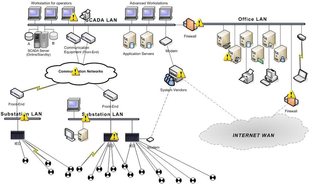
2 SCADA and Systems Monitoring SCADA stands for supervisory control and data acquisition system. There are locations, in most of the power systems, where operations, such as opening and closing circuit breakers, must be done from time to time, but the cost of providing and maintaining operator attendance cannot be justified. Sending an operator to such locations could results in delay in some cases, as a result the outage may be lengthen and end up in total failure in some cases.
3 SCADA and Systems Monitoring Moreover, the cost of providing attendance at remote stations or providing personnel to perform switching continues to rise. This makes operator attendance of remote stations even more uneconomical. Devices to control equipment remotely have been used for many years. The need for remote indication as well as control led to the development of equipment that could perform operations, monitor them, and report back.
4 SCADA and Systems Monitoring At the same time it is often important to transmit such information as loads and bus voltages to an operating center, to make corrective action in case of a violation. Almost all modern dispatch and operating centers of power systems are now provided with at least some SCADA system equipment. These equipment have proven to be efficient and economical for power system operations. It is a very effective aid for station operators, making it possible for them to maintain relatively complete knowledge of conditions on the portions of the system
5 SCADA and Systems Monitoring The SCADA system allows a few operators to monitor the generation and high-voltage transmission systems and to take action to correct overloads or out-of limits.
6 Control and Supervision The term supervisory control is normally applied to remote operation of devices such as motors and circuit breakers. The term supervision means signaling back to indicate that the intended operation has been carried out. Simple supervisory control systems have been used since early days of utility operations. The supervision was provided by lights in early systems. Green light to indicate an open device and red to indicate the contrary
7 Control and Supervision In such systems, wires between the control point and the controlled device being were required for each device being controlled and supervised remotely. When there are many such devices involved, the cost and complexity of supervisory schemes increased directly with the number of devices to be controlled remotely. Moreover, when significant distances were involved, the associated costs were increasingly high and reliability suffered because of the induced electrical noise in the control circuit. The possibility of physical failure has also increased due to such long control circuit.
8 Control and Supervision Some of the shortcomings of direct-wire circuits between the controlling and controlled equipment on a one-for-one basis were minimized by use of the selective relays. By such means it was possible to select the device to be controlled, operate it, and transmit a supervision signal back to the control center over a single control circuit. This type of systems became complex, and sometimes difficult to maintain. They were also limited in speed of operation, and in maximum data transfer when the number of controlled and supervision devices became large.
9 Control and Supervision The arrival of electronic communication methods and digital data transmission provide a means of greatly increasing the capabilities of supervisory control. Sequential scanning and supplied with remote supervisory terminal units, made it possible for one master station to control several remote stations and many devices at each remote station. It was possible to telemeter the control actions taken by the remote units as well as live analog data on current, voltage and many other items needed for the complete supervision of remote station.
10 Control and Supervision Reduction in data transferred between the remote units and the master station was done by a procedure known as exception reporting. This means certain data are transferred only when they change or fall outside previously set limits. These developments made it possible for central location equipped with a supervisory masters station to have almost complete control, and information concerning the status of stations under the control of a single master station.
11 Control and Supervision In most of the systems, the master unit sequentially scans the remote terminal units (RTUs) by sending short message. If it does, the RTU will send a message back to the master, and the data received will be stored into the computer. If necessary, a control message will be sent to the RTU, and an alarm or message will be printed on the master typewriter and displayed on the cathode-ray-tube (CRT) screen. The scan cycle of RTUs is 2s
12 Control and Supervision However, in the event of trouble at a remote station, a message will be sent from remote station to master unit. In some cases, the master units can automatically perform predetermined control action.
13 Control and Supervision All modern supervisory control systems are computerbased; that is the master unit consists of a digital computer with input and output equipment. The input and output equipment are used to send and receive information from RTUs. The received information is displayed on CRTs and/or printed on electric typewriters for permanent records. CRTs can also display graphic information, such as oneline diagrams of the remote stations. In many control centers, overall system status is also shown on wall diagrams, which are kept current with existing conditions by data from the remote terminals.
14 Configuration of SCADA systems Basic elements in a SCADA system are a master unit and RTUs. Links with MU and RTUs were made through communication channels. A number of configurations can be used depending on the requirement, availability of communication channel, and cost.
15 Configuration of SCADA systems (a) One-for-one SCADA system. M R
16 Configuration of SCADA systems (b) STAR or HUP SCADA system. R R M R R
17 Configuration of SCADA systems (c) Party-line SCADA system. M R R R R
18 Configuration of SCADA systems (c) Combination of STAR and Party-line SCADA system. R R M R R R R R
19 Configuration of SCADA systems Reliability of SCADA systems can also be increased by providing alternative communication channels. The overall reliability of a system can be no better than that of the communications communication channels are exposed to various hazards, they usually the least reliable part of SCADA systems.
20 Supervisory Master Units Master unit of SCADA is the heart of the system All operator-initiated operations of an RTU are made through the master unit and are reported back to the master from the RTUs. Modern supervisory master units consist of a digital computer and equipment to permit communications between the master unit and RTUs. Such equipment includes modems to convert the digital pulses used by computer to a form that can be transmitted and received from and RTUs.
21 Supervisory Master Units In addition to the computer, peripheral necessary for the proper operation of the system is provided. (a) (b) (c) (d) A control console Keyboards or other means for the purpose of entering the data CRTs or monitors Printers In some cases, a simplified one-line diagram of the power system is supplied in the form of a large wall map that shows when stations are normal and abnormal conditions exist.
22 Supervisory Master Units When an operation is performed from a SCADA master unit, every effort is made to ensure that the desired device is selected and that the correct operation is chosen. The operator at the master station follows a procedure called the select before operate method.
23 Supervisory Master Units Select before operate method o The operator selects the remote station. o The remote station acknowledges that it has been selected. o The operator selects the device to be operated. o The RTU acknowledges that the device has been selected. o The operator performs the operation. o The RTU carry out the operation and signal back to the master unit that it has been performed.
24 Supervisory Remote Units These are located at some selected stations. They are either wired to perform certain pre-selected functions, or in modern units, equipped with microcomputers which have memory and logic capabilities. RTUs with microcomputer called intelligent remotes Can perform some functions without the direction of the master unit.
25 Supervisory Remote Units However, any operation performed reported back to the master unit in the next scan. The RTUs can also drive a new element, the programmable controller (PC), a dedicated controller with memory and logic. The RTUs are also equipped with modems so that they accept messages from master and signal back to the master Relays located at the RTUs are used to open or close the selected control circuits to be controlled equipment on command from master unit
26 Supervisory Remote Units Transducers in the remote units are used to convert measurement such as voltage, current, watts, and vars to direct current or voltage signals proportional to the respective measured quantity. Then A/D converters are used to convert the measured quantity into digital form.
27 Communication for SCADA Systems Communication is an essential part of SCADA systems. The communication links can be wire circuits, microwave channel, or power line carrier channels. Any communication circuit that provides an adequate signal to noise ratio and has a bandwidth capable of passing the data signals at the rate at which they are transmitted can be used.
28 Communication for SCADA Systems Communication is an essential part of SCADA systems. The communication links can be wire circuits, microwave channel, or power line carrier channels. Any communication circuit that provides an adequate signal to noise ratio and has a bandwidth capable of passing the data signals at the rate at which they are transmitted can be used.
29 Communication for SCADA Systems In most application, a normal telephone voice channel of about 400 to 3400 Hz bandwidth is satisfactory. For low speed data transmission, a narrow bandwidth, usually located above the highest voice frequency, can be used. In such cases, the voice band is restricted to about 400 to 2200 Hz, and the data are transmitted from 2200 to 3400 Hz.
30 Communication for SCADA Systems This type of operation is called Speech-plus, and it provides for both voice and data communication on a single voice channel, with a somewhat degraded voice channel. It should be stressed that communication is of primary importance for SCADA system. Poor communication results in errors or lost messages. A system cannot function properly without reliable and adequate communication channels.
31 Energy Management Systems (EMS) For a power system to be able to supply to all its customers within acceptable voltage and frequency limits, it must be able to over come some unavoidable disturbances. Some of these disturbances could be quite abnormal, but nevertheless credible; such disturbances are: Line outages following shunt faults Equipment failure and subsequent isolation Switch surges and lightning strikes Mechanical damages (due to wind, snow storm)
32 Energy Management Systems (EMS) Some of these disturbances can be dealt with the help of protective devices and the system restored back to normal stage within few cycles. Other disturbances may cause transient oscillations, which could last for several seconds, producing large oscillations in power flow. This results in abnormal voltage and frequency and subsequent tripping of plant items. For this purpose and other reasons an Energy Management System is vital for any power systems.
33 Energy Management Systems (EMS) An EMS enables engineers to operate and control the network in real time and includes facilities to capture the current state of the system and to instruct generating plants and other controllable system components such that all the customers are supplied, at least cost, with security. Considerable back-up facilities are necessary, including special software programs, display facilities, and support staff.
34 Energy Management Systems (EMS) Hierarchy of power system with EMS Central Coordinating Control Level 3 Area Control Level 2 Local Control Level 1 Network and Substations Level 0
35 Energy Management Systems (EMS) At level 0 is the power system with isolators, switchgears, interconnections, transmission lines, cables, transformers, etc are located; At level 1 substation (local) controls are located. The local controls at level 1 may include protection relays, tap-change controllers, and compensator controls, with operating channels to the level 0 units.
36 Energy Management Systems (EMS) Level 1 controls often comprise digital/electronic devices for voltage and current measurement, inter locking and facilities for receiving and sending data to the next level up (area concentrators). In many cases, level 1 consists of racks of electronics within RTUs. At level 2, man-machine interfacing and data concentrators enable control and maintenance to be exercised so that the whole system can be kept in reliable and efficient condition.
37 Energy Management Systems (EMS) At the top level (3), the SCADA system resides, usually in a single control center (variously called Pool, National, or System control).
38 Energy Management Systems (EMS) The SCADA system accepts data from the various level 1 collectors and displays it in a meaningful way to the control engineers or operators, usually by one-line mimic diagram on a Colour video screen as seen in the previous section. The EMS processes SCADA data in various ways, including topology identification by using the dynamic data from switch-gear, isolators and other system connectors.
39 Energy Management Systems (EMS) Some EMS functions are: State estimation Security analysis Voltage reduction Load shedding Load forecasting
40 Energy Management Systems (EMS) State estimation (Power System State Estimation - PSSE) PSSE is a process in which data telemetered from network measuring points to a central computer, can be formed into a set of reliable data (the data base ) for control and recording purpose.
41 Flexible AC Transmission System Alternating current transmission systems incorporating power electronics-based and other static controllers to enhance controllability and increase power transfer capability

42 Large Electric Power Systems Simple illustration of the power transmission system Power system structure S = P + jq Pi Qi = PGenerator + PLoad + PCompensation = QGenerator + QLoad + QCompensation
43 Apparent Complex Power: S = P + jq Real Power: P V X 2 sin Reactive Power: 2V Q V * I * sin( / 2) * (1 cos ) X 2 V voltage X reactance phase angle I current

44 FACTS devices = Flexible Alternating Current Transmission System devices Direct control of power flow over designated transmission routes Fast Control Technology to overcome limitations to Power Transfer Capability through rapid response P V X 2 * sin

45 What is FACTS? The FACTS technology is a collection of controllers, which can be applied individually or in coordination with others to control one or more of the interrelated system parameters, such as series impedance, shunt impedance, current, voltage, and damping of oscillations.
46 What limits the Loading Capability? Thermal For overhead line, thermal capability is a function of ambient temperature, wind conditions, conditions of conductor, and ground clearance. The FACTS technology can help in making an effective used of newfound line capability. Dielectric Being designed very conservatively, most lines can increase operation voltage by 10% or even higher. FACTS technology could be used to ensure acceptable over-voltage and power flow conditions. Stability The stability issues that limit the transmission capability include: transient stability, dynamic stability, steady-state stability, frequency collapse. Voltage collapse, and sub-synchronous resonance. The FACTS technology can certainly be used to overcome any of the stability limits.

47 A Simple Example of FACTS
48 Basic types of FACTS Controllers Series controllers: The series controller could be a variable impedance or a variable source both are power electronics based. In principle, all series controllers inject voltage in series with the line. Shunt controllers: The shunt controllers may be variable impedance connected to the line voltage causes a variable current flow hence represents injection of current into the line. Combined series-series controllers: The combination could be separate series controllers or unified series-series controller--- Interline Power Flow Controller. Combined series-shunt controllers: The combination could be separated series and shunt controllers or a unified power flow controller
49 Relative Importance of Different Types of Controllers For a given MVA size, the series controller is several times more powerful than the shunt controller in application of controlling the power/current flow. Drawing from or injecting current into the line, the shunt controller is a good way to control voltage at and around the point of connection. The shunt controller serves the bus node independently of the individual lines connected to the bus. Series connected controllers have to be designed to ride through contingency and dynamic overloads, and ride through or bypass short circuit currents. A combination of series and shunt controllers can provide the best of effective power/current flow and line voltage. FACTS controllers may be based on thyristor devices with no gate turn-off or with power devices with gate turn-off capability. The principle controllers are based on the dc to ac converters with bidirectional power flow capability.
50 Relative Importance of Different Types of Controllers Energy storage systems are needed when active power is involved in the power flow. Battery, capacitor, superconducting magnet, or any other source of energy can be added in parallel through an electronic interface to replenish the converter s dc storage. A controller with storage is more effective for controlling the system dynamics. A converter-based controller can be designed with high pulse order or pulse width modulation to reduce the low order harmonic generation to a very low level. A converter can be designed to generate the correct waveform in order to act as an active filter. A converter can also be controlled and operated in a way that it balances the unbalanced voltages, involving transfer of energy between phases. A converter can do all of these beneficial things simultaneously I the converter is so designed.
51 Brief Description and Definitions of FACTS controllers Shunt connected controllers Series connected controllers Combined shunt and series connected controllers

52 Shunt connected controllers
53 Series connected controllers
54 Combined shunt and series connected controllers
55 Other controllers

56 SVC, Static VAR Compensator (shunt connected controller) Note: The control strategy usually aims to maintain the transmission line voltage at a fixed level.

57 STATCOM, Static Compensator---Advanced Static VAR Compensator (shunt connected controller) The main features: 1. Wide operating range 2. Lower rating than SVC 3. Increased transient rating and superior capability to handle dynamic system disturbances

58 TCSC, thyristor-controlled series capacitor (series-connected controller) Note: The TCSC behaves as a tunable parallel LC-circuit to the line current. As the impedance of XL is varied from its maximum (infinity) toward its minimum wl, the TCSC increases its capacitive impedance.

59 UPFC, unified power flow controller (combined shunt and series connected controllers) 1. The UPFC consists of an a series STATCOM and a shunt SATACOM with a common DC link. 2. Power control is achieved by adding series voltage Vinj to Vs, thus giving the line voltage VL. 3. With two converters, the UPFC can supply active power in addition to reactive power.
60 UPFC Capabilities Increase transmission line capacity Direct power flow along selected lines Powerful system oscillation damping Voltage support and regulation Control of active and reactive power flow at both sending- and receiving-end

61 Operation Reactive power is generated or absorbed by the shunt inverter to control bus voltage Reactive power is generated or absorbed by the series inverter to control the real and/or reactive power flow on the transmission line. A portion of the real power flow on the transmission line is drawn from the bus by the shunt inverter to charge the DC capacitor. Real power is inserted into the line through the series inverter.
62 Power flow in a transmission line V S jx V R P SR VV S X R sin and V V jxi R S P SR V R jxi V S To increase P SR, increase
63 V A - V inj + V B V B V inj V A V S jx V R - V + inj VV S R V P sin R SR X V R P SR V inj jxi V S
64 How is V inj created? a 1 b 1 c 1 + V a 2 b 2 c 2
65 a 1 on, b 1 on, c 1 off V ab =0, V bc =V, V ca = -V a 1 a 2 b 1 b 2 c 1 c 2 + V a 1 on, b 1 off, c 1 off V ab =V, V bc =0, V ca = -V a 1 b 1 c 1 a 2 b 2 c 2 + V a 1 on, b 1 off, c 1 on V ab =V, V bc =-V, V ca = 0 a 1 b 1 c 1 a 2 b 2 c 2 + V
66 Introduction Electric power transmission was originally developed with direct current. The first commercial HVDC line built in 1954, a 98 km submarine cable with ground return between the island of Gotland and the Swedish mainland. Thyristors were applied to D C transmission in the late 1960 s and solid state valves became a reality. D.C. transmission is now an integral part of the delivery of electricity in many countries throughout the world.
67 Introduction A high-voltage, direct current (HVDC) electric power transmission system uses direct current for the bulk transmission of electrical power. For long-distance transmission, HVDC systems may be less expensive and suffer lower electrical losses. For underwater power cables, HVDC avoids the heavy currents required by the cable capacitance. HVDC allows power transmission between unsynchronized AC distribution systems, and can increase system stability by preventing cascading failures from propagating from one part of a wider power transmission grid to another.

68 Why HVDC systems?
69 Why HVDC An overhead d.c. transmission line with its towers can be designed to be less costly per unit of length than an equivalent a.c. line designed to transmit the same level of electric power. However the d.c. converter stations at each end are more costly than the terminating stations of an a.c. line and so there is a breakeven distance above which the total cost of d.c. transmission is less than its a.c. transmission alternative. The d.c. transmission line can have a lower visual profile than an equivalent a.c. line and so contributes to a lower environmental impact. There are other environmental advantages to a d.c. transmission line through the electric and magnetic fields being d.c. instead of ac. If transmission is by submarine or underground cable, the breakeven distance is much less than overhead transmission. It is not practical to consider a.c. cable systems exceeding 50 km but d.c. cable transmission systems are in service whose length is in hundreds of kilometers and even distances of 600 km or greater have been considered feasible. Some a.c. electric power systems are not synchronized to neighboring networks even though their physical distances between them are quite small. It is physically impossible to connect the two together by direct A.C methods in order to exchange electric power between them. However, if a d.c. converter station is located in each system with an interconnecting d.c. link between them, it is possible to transfer the required power flow even though the a.c. systems so connected remain asynchronous.
70 HVDC Advantages 1. Interconnections between asynchronous systems. 2. Deliver energy from remote energy sources. Where generation has been developed at remote sites of available energy, HVDC transmission has been an economical means to bring the electricity to load centers. Gas fired thermal generation can Import electric energy into congested load areas. 3. Increasing the capacity of existing a.c. transmission by conversion to d.c. transmission. 4. New transmission rights-of-way may be impossible to obtain. Existing overhead a.c. transmission lines if upgraded to or overbuilt with d.c. transmission can substantially increase the power transfer capability on the existing right-of-way. 5. Power flow control. A.c. networks do not easily accommodate desired power flow control. Power marketers and system operators may require the power flow control capability provided by HVDC transmission. 6. Stabilization of electric power networks. Some wide spread a.c. power system networks operate at stability limits well below the thermal capacity of their transmission conductors. HVDC transmission is an option to consider to increase utilization of network conductors along with the various power electronic controllers which can be applied on a.c. transmission.
71 Advantages over HVAC Bulk Power transfer with lower capital costs and with lower losses than AC. In many applications HVDC is more effective than AC transmission. Undersea cables, where high capacitance causes additional AC losses. Endpoint-to-endpoint long-haul bulk power transmission without intermediate 'taps'. Increasing the capacity of an existing power grid in situations where additional wires are difficult or expensive to install Power transmission and stabilization between unsynchronized AC distribution systems Connecting a remote generating plant to the distribution grid. Stabilizing a predominantly AC power-grid, without increasing prospective short circuit current Reducing line cost. HVDC needs fewer conductors as there is no need to support multiple phases. Thinner conductors can be used since HVDC does not suffer from the skin effect Facilitate power transmission between different countries that use AC at differing voltages and/or frequencies Synchronize AC produced by renewable energy sources

72 BASIC HVDC Topology
 by submarine cable, the only applicable technology is the HVDC transmission.")
73 HVDC transmission The HVDC transmission has the major advantage of flexibility in power exchange in comparison with HVAC. Moreover, in case of transmission of bulk electrical energy over long distances (more than 50 km) by submarine cable, the only applicable technology is the HVDC transmission. HVDC is an intelligent link. The power flow can be controlled and changed very quickly practically independently from frequency at the terminal busses, voltage or power angle at the terminal busses like in HVAC transmission. Due to the inherent properties of the electronic equipment which forms the converter bridges, the direction of the transmitted power may be also changed very quickly.
 - Converted back to AC in another converter station - Injected into AC network Controllable power injected where needed,supplemental control, frequency control - Bypass")
74 HVDC transmission principles and characteristics In a HVDC system, the electricity is: - Taken from a 3-phase AC network - Converted to DC in a converter station - Transmitted by DC OHL or cable (underground or sub sea) - Converted back to AC in another converter station - Injected into AC network Controllable power injected where needed,supplemental control, frequency control - Bypass congested circuits no inadvertent flow - Higher power, fewer lines,no intermediate S/S needed - Lower losses - Facilitates integration of remote diverse resources with less impact on existing grid - Low expensive transmission line - Reactive power demand limited to terminals independent of distances - Narrower ROW, no EMF constraints - No limit to underground or submarine cable length
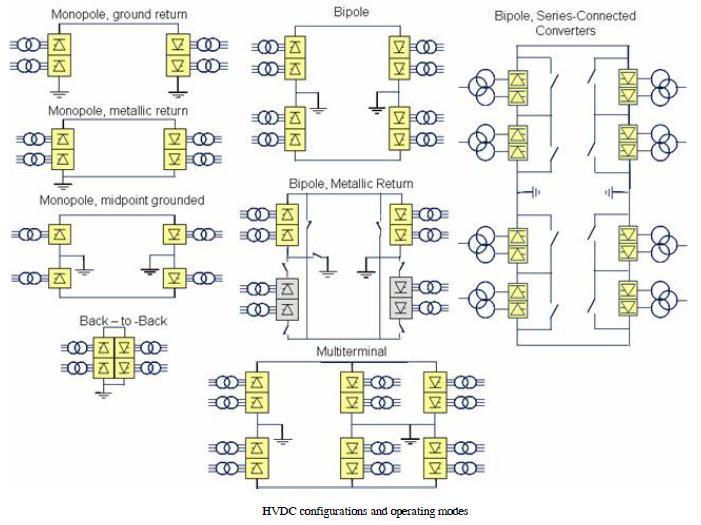
75 HVDC CONFIGURATION
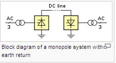
76 MONOPOLAR AND EARTH RETURN 1. One of the terminals of the rectifier is connected to earth ground. The other terminal, at a potential high above or below ground, is connected to a transmission line. 2. The earthed terminal may be connected to the corresponding connection at the inverting station by means of a second conductor. 3. If no metallic conductor is installed, current flows in the earth between the earth electrodes at the two stations. 4. Therefore it is a type of single wire earth return. The issues surrounding earth-return current include: Electrochemical corrosion of long buried metal objects such as pipelines Underwater earth-return electrodes in seawater may produce chlorine or otherwise affect water chemistry. An unbalanced current path may result in a net magnetic field, which can affect magnetic navigational compasses for ships passing over an underwater cable. 5. These effects can be eliminated with installation of a metallic return conductor between the two ends of the monopolar transmission line. 6. Since one terminal of the converters is connected to earth, the return conductor need not be insulated for the full transmission voltage which makes it less costly than the high-voltage conductor. 7. Use of a metallic return conductor is decided based on economic, technical and environmental factors. 8. Modern monopolar systems for pure overhead lines carry typically 1,500 MW. If underground or underwater cables are used, the typical value is 600 MW. 9. Most monopolar systems are designed for future bipolar expansion. 10. Transmission line towers may be designed to carry two conductors, even if only one is used initially for the monopole transmission system.
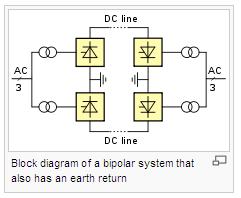
77 BIPOLAR 1. In bipolar transmission a pair of conductors is used, each at a high potential with respect to ground, in opposite polarity. 2. Since these conductors must be insulated for the full voltage, transmission line cost is higher than a monopole with a return conductor. 3. Advantages to bipolar transmission. Under normal load, negligible earth-current flows, as in the case of monopolar transmission with a metallic earth-return. This reduces earth return loss and environmental effects. When a fault develops in a line, with earth return electrodes installed at each end of the line, approximately half the rated power can continue to flow using the earth as a return path, operating in monopolar mode. Since for a given total power rating each conductor of a bipolar line carries only half the current of monopolar lines, the cost of the second conductor is reduced compared to a monopolar line of the same rating. In very adverse terrain, the second conductor may be carried on an independent set of transmission towers, so that some power may continue to be transmitted even if one line is damaged. 4. A bipolar scheme can be implemented so that the polarity of one or both poles can be changed. 5. This allows the operation as two parallel monopoles. 6. If one conductor fails, transmission can still continue at reduced capacity. 7. Losses may increase if ground electrodes and lines are not designed for the extra current in this mode. To reduce losses in this case, intermediate switching stations may be installed, at which line segments can be switched off or parallelized.
78 BACK to BACK A back-to-back station (or B2B for short) is a plant in which both static inverters and rectifiers are in the same area, usually in the same building. The length of the direct current line is kept as short as possible. HVDC back-to-back stations are used for Coupling of electricity mains of different frequency (as in Japan; and the GCC interconnection between UAE [50 Hz] and Saudi Arabia [60 Hz] under construction in ± ) Coupling two networks of the same nominal frequency but no fixed phase relationship Different frequency and phase number. The DC voltage in the intermediate circuit can be selected freely at HVDC back-to-back stations because of the short conductor length.
79 OTHER HVDC CONFIGURATIONS

80 Components of HVDC System
81 Rectification and inversion use essentially the same machinery. Many substations (Converter Stations) are set up in such a way that they can act as both rectifiers and inverters. At the AC end a set of transformers, often three physically separated single-phase transformers, isolate the station from the AC supply, to provide a local earth, and to ensure the correct eventual DC voltage. The output of these transformers is then connected to a bridge rectifier formed by a number of valves. The basic configuration uses six valves, connecting each of the three phases to each of the two DC rails. However, with a phase change only every sixty degrees, considerable harmonics remain on the DC rails. In addition to the conversion transformers and valve-sets, various passive resistive and reactive components help filter harmonics out of the DC rails.
82 HVDC Disadvantages The disadvantages of HVDC are in conversion, switching, control, availability and maintenance. HVDC is less reliable and has lower availability than alternating current (AC) systems, mainly due to the extra conversion equipment. The required static inverters are expensive and have limited overload capacity In contrast to AC systems, realizing multiterminal systems is complex, as is expanding existing schemes to multiterminal systems. Controlling power flow in a multiterminal DC system requires good communication between all the terminals HVDC circuit breakers are difficult to build because some mechanism must be included in the circuit breaker to force current to zero, otherwise arcing and contact wear would be too great to allow reliable switching. Operating a HVDC scheme requires many spare parts to be kept, often exclusively for one system, as HVDC systems are less standardized than AC systems and technology changes faster.
CHAPTER 4 FACTS CONTROLLERS FOR OPTIMIZATION OF POWER SYSTEM
 52 CHAPTER 4 FACTS CONTROLLERS FOR OPTIMIZATION OF POWER SYSTEM 4.1 INTRODUCTION Flexible AC Transmission System (FACTS) controllers have been used in power systems with the objective of improving system
ELG4125: System Protection
 ELG4125: System Protection System Protection Any power system is prone to 'faults', (also called short-circuits), which occur mostly as a result of insulation failure and sometimes due to external causes.
The Different Types of UPS Systems
 The Different Types of UPS Systems White Paper # 1 Revision 4 Executive Summary There is much confusion in the marketplace about the different types of UPS systems and their characteristics. Each of these
Real-time Power System Operation. Energy Management Systems. Introduction
 1 Real-time Power System Operation Energy Management Systems Introduction The time frame for Power Systems Operation varies from a few seconds to a week. To assist with the operation of the system, modern
Small Generator Interconnection System Impact Study Report. Completed For Q0047
 Small Generator Interconnection Completed For Q0047 Proposed Interconnection PacifiCorp s Existing Goshen Rigby 69 kv Line March 7, 2005 1.0 Description of the Generation Facility Q0047 ( Interconnection
MAHALAKSHMI ENGINEERING COLLEGE TIRUCHIRAPALLI EE-2401 POWER SYSTEM OPERATION AND CONTROL UNIT-III REACTIVE POWER VOLTAGE CONTROL
 MAHALAKSHMI ENGINEERING COLLEGE TIRUCHIRAPALLI 621213 EE-2401 POWER SYSTEM OPERATION AND CONTROL UNIT-III REACTIVE POWER VOLTAGE CONTROL TWO MARKS: 1. What are the sources of reactive power? How it is
IJSRD - International Journal for Scientific Research & Development Vol. 3, Issue 10, 2015 ISSN (online):
:") IJSRD - International Journal for Scientific Research & Development Vol. 3, Issue 10, 2015 ISSN (online): 2321-0613 Comparison of Shunt Facts Devices for the Improvement of Transient Stability of Two Machine
IJSRD - International Journal for Scientific Research & Development Vol. 3, Issue 10, 2015 ISSN (online): 2321-0613 Comparison of Shunt Facts Devices for the Improvement of Transient Stability of Two Machine
POWER SYSTEM SECURITY CONCEPTS
 POWER SYSTEM SECURITY CONCEPTS 1.1 INTRODUCTION The Power System needs to be operationally secure, i.e. with minimal probability of blackout and equipment damage. An important component of power system
Final Report. Mini Project TET Group nr 7 - Project nr 4. Students: Hans Lavoll Halvorson, NTNU
 Final Report Mini Project TET4190 28.10.2010 Optimal Distance for connection of offshore wind farm with AC cable with SVC or STATCOM To increase the distance compensation technologies such as SVC and STATCOM
Chapter 3 MODELING OF SHUNT FACTS DEVICES. The Shunt FACTS Devices are used for voltage control and
 44 Chapter 3 MODELING OF SHUNT FACTS DEVICES 3.0 Introduction The Shunt FACTS Devices are used for voltage control and power flow control, but these are good at for voltage control. These are not in a
Shabnam Rukhsar Electrical Engineering Department, Anjuman College of Engineering and Technology.India
 SCADA in Transmission Line Shabnam Rukhsar Electrical Engineering Department, Anjuman College of Engineering and Technology.India ABSTRACT: Transmission line equivalent circuit parameters are often 25%
R E C T I F I E R I N V E R T E R C O N V E R T E R MP7
 Uninterruptible Power Supply Product Specifications Description The industrial UPS provides your critical equipment with uninterruptible 3 phase AC power. Using high frequency dual conversion technology,
Control and Protection System Win-TDC
 HVDC Control & Protection Control and Protection System Win-TDC HVDC Aysen -SIC Basics of HVDC Basic Design Equipment Info Control & Protection Station Design Logistics Project Management Maintenance 1
April 2010 Power Systems division A brief introduction. ABB Group August 25, 2011 Slide 1
 April 2010 Power Systems division A brief introduction August 25, 2011 Slide 1 Facts about ABB 117,000 employees in about 100 countries $32 billion in revenue (2009) Formed in 1988 merger of Swiss and
MP7. Uninterruptible Power Supply
 Uninterruptible Power Supply PRODUCT SPECIFICATIONS Description The industrial UPS provides your critical equipment with uninterruptible 3 phase AC power. Using high frequency dual conversion technology,
Mehta Tech, Inc. TRANSCAN IED For Multi-Function, Multi-Speed Recording
 Mehta Tech, Inc. TRANSCAN IED For Multi-Function, Multi-Speed Recording Two independent, simultaneously operating recorders in one package Triggering on input quantities and calculated values, such as
Awareness of the Situation
 17/11/21 Situational Awareness UPDEA - Workshop Awareness of the Situation 25,623 Alarms in 8 ours 53 Alarms / min (average) 8% Are consequential Things 1 to keep in mind during a disturbance - Analog
The Study of Voltage Profile and Power Quality with SVC in Transmission System at Different Loads
 The Study of Voltage Profile and Power Quality with SVC in Transmission System at Different Loads S.RaviKumar, B.Ramoji Rao, D.Ramesh Abstract This paper illustrates the effect of different static load
AUTOMATION OF POWER DISTRIBUTION USING SCADA
 1 2 ABSTRACT In every substation certain measurements, supervision, control, operation and protection functions are necessary. Traditionally these functions were performed manually by system operator from
LAB1 INTRODUCTION TO PSS/E EE461: POWER SYSTEMS COLORADO STATE UNIVERSITY
 LAB1 INTRODUCTION TO PSS/E EE461: POWER SYSTEMS COLORADO STATE UNIVERSITY PURPOSE: The purpose of this lab is to introduce PSS/E. This lab will introduce the following aspects of PSS/E: Introduction to
Fault Analysis of Distribution Network with Flexible Ring Network Control Device
 6th International Conference on Advanced Design and Manufacturing Engineering (ICADME 2016) Fault Analysis of Distribution Network with Flexible Ring Network Control Device Kuo Tan 1, a, Chenghong Tang
White Paper. AC Surge Protection. Evaluation of Series Element Surge Protective Device for Protection of Electronic Equipment and Systems
 White Paper AC Surge Protection Evaluation of Series Element Surge Protective Device for Protection of Electronic Equipment and Systems Richard Odenberg, Research & Advanced Applications, Founder of Transtector
ELECTRICAL, INSTRUMENTATION & CONTROL SYSTEMS
 ELECTRICAL, INSTRUMENTATION & CONTROL SYSTEMS Presentation by: RANA NASIR ALI General Manager, Power Plants Projects, at PITCO November 02, 2017 ELECTRICAL PLANT CONCEPT The electrical equipment, depending
The various functions of an energy control center can be enumerated as under: 1. Load forecasting 6. Automatic generation control
 ENERGY CONTROL CENTERS To generated, Transmission and Distribution system, Number of customers and Total investment. Installed capacity in India exceeds 206 GW with annual energy generated energy exceeding
Chapter 2 State Estimation and Visualization
 Chapter 2 State Estimation and Visualization One obvious application of GPS-synchronized measurements is the dynamic monitoring of the operating conditions of the system or the dynamic state estimation
Testing of Real Time Power System Control Software
 Testing of Real Time Power System Control Software Transpower s Pole 3 Project Presentation to Special Interest Group of ANZTB 7 October 2013 Richard Sherry 1 Summary 1. What does the HVDC Control System
TFS 2100 Traveling Wave Fault Location System
 Traveling Wave Fault Location System The most accurate overhead transmission and distribution line fault locator Accuracy: ±150m typical regardless the line length Unaffected by fault resistance Suitable
Advanced Line Differential Protection, Automation, and Control System. Combine subcycle line protection with traveling-wave fault locating
 Advanced Line Differential Protection, Automation, and Control System Combine subcycle line protection with traveling-wave fault locating Subcycle differential and distance protection minimizes damage
Revised Generation Interconnection Impact Study Report. For. Queue Position 31 ( Interconnection Customer )
") Revised Generation Interconnection Impact Study Report For Queue Position 31 ( Interconnection Customer ) September 22, 2004 1 Generation Interconnection System Impact Study Report I. Revision of Original
Revised Generation Interconnection Impact Study Report For Queue Position 31 ( Interconnection Customer ) September 22, 2004 1 Generation Interconnection System Impact Study Report I. Revision of Original
C C CIRCUIT-BREAKERS Moulded-case (MCCB), general. 1. Introduction. 2. General description
, general. 1. Introduction. 2. General description") CIRCUIT-BREAKERS C C81-21 CIRCUIT-BREAKERS - Contents 1. Introduction 2. General description 3. Rated voltages 3.1 Rated operational voltage (U e ) 3.2 Rated impulse withstand voltage (U imp ) 3.3 Rated
CIRCUIT-BREAKERS C C81-21 CIRCUIT-BREAKERS - Contents 1. Introduction 2. General description 3. Rated voltages 3.1 Rated operational voltage (U e ) 3.2 Rated impulse withstand voltage (U imp ) 3.3 Rated
4-W HDSL/56Kbps Isolation Card With 130/190V Span Powering. Description & Installation P30140
 4-W HDSL/56Kbps Isolation Card With 130/190V Span Powering Description & Installation P30140 Printed in USA 11/12 TO506 Rev. A Table of Contents 1.0 PRODUCT SCOPE 3 2.0 PRODUCT OVERVIEW 3 2.1 System Requirements
HVDC Control and Protection Testing Using the RTDS Simulator
 HVDC Control and Protection Testing Using the RTDS Simulator Yong-Beum Yoon, Tae-Kyun Kim, Seung-Tae Cha Power System Research Laboratory, Korea Electric Power Research Institute, Korea Abstract: Many
The Efficient Way. SVC PLUS Innovation meets experience. Answers for energy.
 The Efficient Way SVC PLUS Innovation meets experience Answers for energy. Enhancement of Grid Efficiency Improved dynamic stability and power quality of power systems in a new, highly economical manner
Power Quality of Commercial and Industrial Power Systems
 Hanover Risk Solutions Power Quality of Commercial and Industrial Power Systems Power quality is a general term used to describe the quality of several different power-related characteristics. These characteristics
Advanced Monitoring Solutions for Critical Electric Power Transmission & Distribution Assets
 Advanced Monitoring Solutions for Critical Electric Power Transmission & Distribution Assets www.intellisaw.com The Case for Critical Asset* Monitoring The vast majority of critical assets in the field
SVC Light for rail traction The way to effective grid integration
 SVC Light for rail traction The way to effective grid integration The way to effective grid integration The increase in traffic on existing tracks combined with new high-speed rail projects mean rail traction
Evolution of Control for the Power Grid
 Evolution of Control for the Power Grid Anjan Bose Washington State University Pullman, WA, USA PaiFest In Honor of Prof. M. A. Pai Urbana-Champaign, IL October 15, 2015 The Past (before 1960s) Hard
Distribution Static Var Compensators and Static Synchronous Compensators for Suppressing Voltage Fluctuation
 Distribution Static Var Compensators and Static Synchronous Compensators for Suppressing Voltage Fluctuation KOJIMA, Takehiko * ISOTANI, Hitoshi * YAMADA, Makoto * A B S T R A C T The rapidly expanding
Approval...6. Current Revision...7. Introduction... 8 About PJM Manuals... 8 About This Manual... 8 Using This Manual...9
 PJM Manual 07: PJM Protection Standards Revision: 3 Effective Date: May 24, 2018 Prepared by System Planning Division Transmission Planning Department PJM 2018 Table of Contents Table of Contents Approval...6
Power System Network Simulator (PSNsim)
") The PSNsim is hardware simulator that simulates all parts of power system from generation to utilization. The PSNsim is a scaled down model of the real power system that provides an experimental environment
The PSNsim is hardware simulator that simulates all parts of power system from generation to utilization. The PSNsim is a scaled down model of the real power system that provides an experimental environment
Chapter 2 Communication for Control in Heterogeneous Power Supply
 Chapter 2 Communication for Control in Heterogeneous Power Supply The need to modernize the power grid infrastructure, and governments commitment for a cleaner environment, is driving the move towards
3/2/ /2/ :05 AM EET 415/4 Power System Operation 1 3/2/ :05 AM EET 415 2
 Communication in Power System II 3/2/2009 11:05 AM EET 415/4 Power System Operation 1 Communication In Power System II CONTENTS SCADA Definition SCADA Evolution Basic SCADA System Architecture Typical
Call for Papers GCC POWER 2011 GCC Cigre s Leading Electric Power Conference & Exhibition In the Gulf Region
 Call for Papers GCC POWER 2011 GCC Cigre s Leading Electric Power Conference & Exhibition In the Gulf Region Kuwait - November 2011 GCC Cigre, is pleased to announce its 7 th International Conference GCC
IMPROVING POWER SYSTEM RELIABILITY USING MULTIFUNCTION PROTECTIVE RELAYS
 IMPROVING POWER SYSTEM RELIABILITY USING MULTIFUNCTION PROTECTIVE RELAYS Armando Guzmán Schweitzer Engineering Laboratories, Inc. Pullman, WA 99163 A reliable power system maintains frequency and voltage
LIGHTNING AND SURGE PROTECTION
 White Paper LIGHTNING AND SURGE PROTECTION Lightning and Surge Protection 01/20/17 1 of 7 www.murata.com APPLICATION NOTE: LIGHTNING AND SURGE PROTECTION Because wireless systems are typically located
Christian PAYERL, Poznan, 20 th May, 2009 ABB FACTS Grid connection of Wind Farms. ABB Group May 22, 2009 Slide 1
 Christian PAYERL, Poznan, 20 th May, 2009 ABB FACTS Grid connection of Wind Farms May 22, 2009 Slide 1 FACTS Applications Flexible AC Transmission Systems May 22, 2009 Slide 4 System Studies - Grid Codes
PART 1: GENERAL PART 2: PRODUCT. Effective: 12/29/10 Page 1 of 6 FECA-TE-104D
 Specification Number: 23 09 33 Product Name: FRENIC-Eco AC Drives for Variable Torque Fan & Pump Applications (1-125Hp at 208/230V and 1-900Hp at 460V) PART 1: GENERAL 1.01 SUMMARY A. This specification
GRID/PRSHT/MU320/EN/1.2014/GBR/1894 ALSTOM All rights reserved.
 GRID/PRSHT/MU320/EN/1.2014/GBR/1894 ALSTOM 2014. All rights reserved. GRID/PRSHT/MU320/EN/1.2014/GBR/1894 ALSTOM 2014. All rights reserved. MEASUREMENT PRODUCT SOLUTIONS Reason RPV311 Digital fault recorder
Main Components of a Static Var Compensator (SVC)
") Exercise 1 Main Components of a Static Var Compensator (SVC) EXERCISE OBJECTIVE When you have completed this exercise, you will be familiar with the simplified diagram of an SVC. You will also be familiar
Exercise 1 Main Components of a Static Var Compensator (SVC) EXERCISE OBJECTIVE When you have completed this exercise, you will be familiar with the simplified diagram of an SVC. You will also be familiar
Data Sheet. RS Datascan data acquisition system
 Data Pack D Issued March 1997 1502323737 Data Sheet RS Datascan data acquisition system Introduction The RS Datascan range of distributed data acquisition modules provides a flexible, easy to use, cost
Lightning and Surge Protection of Photovoltaic Installations. Leutron GmbH 2013 Leinfelden-Echterdingen, Germany
 Lightning and Surge Protection of Photovoltaic Installations 1 Lightning and Surge Protection for PV Installations 2 Safeguard from Risks Ups, that was the insurance policy of my house!! 3 Why Lightning
SCADA Training - T&D Automation
 SCADA Training - T&D Automation Contact us Today for a FREE quotation to deliver this course at your company?s location. https://www.electricityforum.com/onsite-training-rfq This course covers all the
Substation SCADA Monitoring
 Substation SCADA Monitoring Contact us Today for a FREE quotation to deliver this course at your company?s location. https://www.electricityforum.com/onsite-training-rfq Substations are a critical component
SPECIFIC INTERCONNECTION PROTECTION REQUIREMENTS... 5
 Central Hudson Gas & Electric Corporation (CHG&E) Interconnection Protection Requirements for Distributed Generators of Greater than 300 kva Connected in Parallel with the CHG&E Electrical Delivery System
WECC Criterion MOD-(11 and 13)-WECC-CRT-1.1
-WECC-CRT-1.1") WECC Criterion MOD-(11 and 13)-WECC-CRT-1.1 A. Introduction 1. Title: Steady State and Dynamic Data Requirements 2. Number: MOD-(11 and 13)-WECC-CRT-1.1 3. Purpose: To establish the consistent data requirements
WECC Criterion MOD-(11 and 13)-WECC-CRT-1.1 A. Introduction 1. Title: Steady State and Dynamic Data Requirements 2. Number: MOD-(11 and 13)-WECC-CRT-1.1 3. Purpose: To establish the consistent data requirements
IDM DATA ACQUISITION SYSTEM
 DATA ACQUISITION SYSTEM The a compact and economical multifunction data acquisition system Rendering all Unrivalled product profile Advanced multifunctional distributed data acquisition system Fully multitasking
Medium Voltage Metal-Enclosed Power Capacitor Banks
 66 Carey Road Queensbury, NY 12804 Ph: (518) 792-4776 Fax: (518) 792-5767 www.nepsi.com sales@nepsi.com Medium Voltage Metal-Enclosed Power Capacitor Banks General Northeast Power System s (NEPSI's) medium
Power Quality of Commercial Buildings - Advanced
 Buildings - Advanced Hartford Steam Boiler One State Street P.O. Box 5024 Hartford, CT 06102-5024 Tel: (800) 472-1866 www.munichre.com/hsb May 2017 Background Power quality is a general term used to describe
UNITROL 5000 Excitation Systems for Medium and Large Synchronous Machines
 UNITROL 5000 Excitation Systems for Medium and Large Synchronous Machines Copyright 2000 Photodisc, Inc. 275 371 UNITROL 5000 System Overview The UNITROL 5000 is the most powerful product in the Switzerland
Technical Data Sheet Medium Current Power Surge Filters
 Technologies Technical Data Sheet Medium Current Power Surge Filters Features High performance surge protector for an operating voltage of 0-220Vac Designed to withstand fault and over-voltage conditions
Common Mode Noise The Often Neglected Tenth Power Problem
 A White Paper from the Experts in Business-Critical Continuity Common Mode Noise The Often Neglected Tenth Power Problem by Michael Boyle Executive Summary Computers and other electronic equipment play
MV Network Switchgear, Protection and Control
 MV Network Switchgear, Protection and Control Ravinder Negi Manager, Services Execution INDIA Schneider Electric, New Delhi. Agenda An Overview MV Network Basic Definitions Circuit breaker Switchgear Control
DS1 Isolation Cards. P Wire Card P Wire Card. Description & Installation
 DS1 Isolation Cards P30051 4-Wire Card P30077 2-Wire Card Description & Installation Printed in USA 09/11 T0332 Rev. A Table of Contents Page 1.0 SCOPE 2 2.0 PRODUCT OVERVIEW 2 2.1 System Requirements
SRI LANKA STANDARD CODE OF PRACTICE FOR GRID CONNECTED PHOTOVOLTAIC POWER SYSTEMS SLS 1522:2016
 SRI LANKA STANDARD CODE OF PRACTICE FOR GRID CONNECTED PHOTOVOLTAIC POWER SYSTEMS SLS 1522:2016 BY H S W Karunaratne Assistant Director - Engineering Sri Lanka Standards Institution. 1 DEFINITIONS Ac module:
Exercise 2. Single Bus Scheme EXERCISE OBJECTIVE DISCUSSION OUTLINE. The single bus scheme DISCUSSION
 Exercise 2 Single Bus Scheme EXERCISE OBJECTIVE When you have completed this exercise, you will be familiar with electric power substations using the single bus scheme with bus section circuit breakers.
Analysis of Power System Stability by Using Optimally Located SVC and STATCOM
 Master Thesis on Analysis of Power System Stability by Using Optimally Located SVC and STATCOM XR EE ES 2009:010 Thesis Examiner: Thesis Supervisor: Submitted by: Mehrdad Ghandhari Hector Latorre / Jai
SPI PowerNet requirements for the non-contestable Interface Works at Deer Park Terminal Station
 SPI PowerNet requirements for the non-contestable Interface Works at Deer Park Terminal Station SPI PowerNet Reference: ZD23 Version: 1.1 Issue date: 15 May 2014 Contents 1 Scope... 3 2 Deer Park Terminal
ANNA UNIVERSITY QB ( )
") ANNA UNIVERSITY QB (2003--2008) UNIT I POWER SEMICONDUCTOR DEVICES PART A 1. Draw the V-I characteristics of SCR and mark the holding current and latching current in the characteristics. Nov/Dec04 2. What
ANNA UNIVERSITY QB (2003--2008) UNIT I POWER SEMICONDUCTOR DEVICES PART A 1. Draw the V-I characteristics of SCR and mark the holding current and latching current in the characteristics. Nov/Dec04 2. What
MiCOM P521. Fast Feeder Differential Protection
 01 Fast Feeder Differential Protection The relay provides high-speed two-ended current differential unit protection of overhead lines and underground cables in applications such as ring mains and parallel
Understanding Solid-state relays
 Understanding Solid-state relays Automation.com, August 2009 By TJ Landrum, Product Manager, Eaton Solid-state relays (SSR) are able to perform many of the same tasks as electromechanical relay (EMR)s.
2. Control Pin Functions and Applications
 IMARY CONTROL ( PIN) Module Enable / Disable. The module can be disabled by pulling the below 2.3 V with respect to the Input. This should be done with an open-collector transistor, relay, or optocoupler.
Implementing the protection and control of future DC Grids
 Implementing the protection and control of future DC Grids Hengxu Ha, Sankara Subramanian Innovation and Technology Department, SAS, Alstom Grid 1. The challenge of the DC Grid protection 1 High speed
The Different Types of UPS Systems
 White Paper 1 Revision 7 by Neil Rasmussen > Executive summary There is much confusion in the marketplace about the different types of UPS systems and their characteristics. Each of these UPS types is
SE Engineering, PC strives to be a leader in the power system engineering field by providing our customers with the highest level of quality,
 SE Engineering, PC strives to be a leader in the power system engineering field by providing our customers with the highest level of quality, integrity, and innovation. Our mission is to offer the safest,
PG&E Transmission Interconnection Handbook
 Table of Contents TABLE OF CONTENTS... 1 UPDATE HISTORY... UP-1 INTRODUCTION... IN-1 I-1. PURPOSE... IN-1 I-2. INTRODUCTORY DEFINITIONS... IN-1 I-3. HANDBOOK APPLICABILITY... IN-2 I-3.1. New Load, New
BS 287 DUAL CHANNEL POWER SUPPLY. User Manual. January 2017 V1.0
 BS 287 DUAL CHANNEL POWER SUPPLY User Manual January 2017 V1.0 Table of contents 1.0 SAFETY INSTRUCTIONS... 3 2.0 GENERAL DESCRIPTION PS 289... 4 3.0 MECHANICAL INSTALLATION... 5 4.0 MAINS POWER & SAFETY
A Svc Light Based Technique for Power Quality Improvement for Grid Connected Wind Energy System
 IOSR Journal of Electrical and Electronics Engineering (IOSR-JEEE) e-issn: 2278-1676,p-ISSN: 2320-3331, Volume 7, Issue 5 (Sep. - Oct. 2013), PP 52-58 A Svc Light Based Technique for Power Quality Improvement
ABB static var compensator stabilizes Namibian grid voltage
 Power ABB static var compensator stabilizes Namibian grid voltage factor! Rolf Grünbaum, Mikael Halonen, Staffan Rudin The spectacular dune landscapes of Namibia are a key factor in the country s booming
Collector System Design Considerations for Wind Farms. Sean Carr Ernst Camm S&C Electric Co.
 Collector System Design Considerations for Wind Farms Sean Carr Ernst Camm S&C Electric Co. 1 Overview Challenges in wind farm collector systems Design considerations for collector systems Summary The
Standards Update Notice (SUN) Issued: August 11, 2017
 Issued: August 11, 2017") Standard Information Standard Number: UL 621 Standard Name: Ice Cream Makers Standard Edition and Issue Date: 7 th Edition Dated May 7, 2010 Date of Revision: February 15, 2017 Date of Previous Revision
Standard Information Standard Number: UL 621 Standard Name: Ice Cream Makers Standard Edition and Issue Date: 7 th Edition Dated May 7, 2010 Date of Revision: February 15, 2017 Date of Previous Revision
Modeling and Simulation of Static VAR Compensator Controller for Improvement of Voltage Level in Transmission Lines
 Modeling and Simulation of Static VAR Compensator Controller for Improvement of Voltage Level in Transmission Lines 1 B.T.RAMAKRISHNA RAO, 2 N.GAYATRI, 3 P.BALAJI, 4 K.SINDHU 1 Associate Professor, Department
Medium Voltage Metal-Enclosed Harmonic Filter Systems
 66 Carey Road Queensbury, NY 12804 Ph: (518) 792-4776 Fax: (518) 792-5767 www.nepsi.com sales@nepsi.com Medium Voltage Metal-Enclosed Harmonic Filter Systems General NEPSI s armorvar, medium voltage metal-enclosed
Solutions for transmission network management
 EM SG SOLutions Solutions for transmission network management Energy Management Smart Grid Solutions Solutions for Transmission Network Management Overview Operator Training Simulator Blackout Prevention
LPI SST Surge Filters
 LPI SST Surge Filters Features High performance surge protector for an operating voltage of 200-240Vac Designed to withstand fault and over-voltage conditions of up to 85Vac, as per IEC664 Impulse discharge
D115 The Fast Optimal Servo Amplifier For Brush, Brushless, Voice Coil Servo Motors
 D115 The Fast Optimal Servo Amplifier For Brush, Brushless, Voice Coil Servo Motors Ron Boe 5/15/2014 This user guide details the servo drives capabilities and physical interfaces. Users will be able to
Measurement Systems Datascan Installation and User Guide
 Measurement Systems Datascan Installation and User Guide Supplied By Contents Contents 1. INTRODUCTION... 1 1.1 GENERAL... 1 1.2 DATASCAN MODULE RANGE... 1 1.2.1 Measurement Processors... 1 1.2.2 Analog
FCIs reduce fault-locating times and improve reliability metrics, especially the Customer Average Interruption Duration Index (CAIDI).
.") 1 Intelligent electronic devices (IEDs) are the preferred choice for modernizing the grid. Communication among networks of robust IEDs designed for protection, control, and monitoring (PCM) of the power
1 Intelligent electronic devices (IEDs) are the preferred choice for modernizing the grid. Communication among networks of robust IEDs designed for protection, control, and monitoring (PCM) of the power
ELECTRICITY SUPPLY SYSTEMS OF THE FUTURE
 ELECTRICITY SUPPLY SYSTEMS OF THE FUTURE Rob Stephen President Cigre AFSEC conference March 2017 CIGRE Founded in 1921, CIGRE, the Council on Large Electric Systems, Our Mission:To be the world s foremost
HIGH LEVEL REQUIREMENTS OF FAST SIMULATION AND MODELLING SUITE OF TOOLS FOR FUTURE SELF-HEALING DISTRIBUTION POWER SYSTEM
 HIGH LEVEL REQUIREMENTS OF FAST SIMULATION AND MODELLING SUITE OF TOOLS FOR FUTURE SELF-HEALING DISTRIBUTION POWER SYSTEM A. Valenti* I Bel ** S. Lee *EDF **EPRI E2I ConEdison France USA USA arnaud.valenti@edf.fr
Power System Controls
 Power System Controls Control Schemes Ref: A. P. Meliopoulos, Power System Modeling, 1990-2006 Voltage Control The objective of this control loop is to regulate the voltage at the terminals of the generator.
TWFL - Travelling Wave Fault Location System
 XC-2100E TWFL - Travelling Wave Fault Location System SCOPE is dedicated to the innovative use of electronics for Test & Measuring applications since 1988 for the Power Industry. Our approach of seeking
Basics of Industrial Electricity and Troubleshooting Electrical Control Circuits
 Basics of Industrial Electricity and Troubleshooting Electrical Control Circuits Course Details Date: January 28 January 31, 2019 Time: 8:00 A.M. - 4:30 P.M. Capacity: 12 attendees Provider: National Technology
Concept of Automation in Management of Electric Power Systems Richard Joseph, Nerey Mvungi
 Concept of Automation in Management of Electric Power Systems Richard Joseph, Nerey Mvungi Abstract An electric power system includes a generating, a transmission, a distribution, and consumers subsystems.
A P P L I C A T I O N
 Circuit Breaker timing test set 16 timing channels Motion and speed analyzer Built-in 200 A microohmmeter Up to 4 trip/close coils control Static and dynamic contact resistance measurement Suitable for
MiCOM P521. Fast feeder differential protection
 01 Fast feeder differential protection The relay provides high-speed two-ended current differential unit protection of overhead lines and underground cables in applications such as ring mains and parallel
Static Var Compensator: Effect of Fuzzy Controller and Changing Membership Functions in its operation
 International Journal of Electrical Engineering. ISSN 0974-2158 Volume 6, Number 2 (2013), pp. 189-196 International Research Publication House http://www.irphouse.com Static Var Compensator: Effect of
DGSZV-EP DIGITAL GALVANIC LONGITUDINAL DIFFERENTIAL PROTECTION. Application field
 DGSZV-EP DIGITAL GALVANIC LONGITUDINAL DIFFERENTIAL PROTECTION The digital galvanic longitudinal differential protection of type DGSZV-EP is part of device family named EuroProt. This short description
Microprocessor protection and automation devices
 Microprocessor protection and automation devices THE ТЭМП 2501 MICROPROCESSOR PROTECTION TERMINALS It is well known that microprocessor protection devices have indisputable advantages over electromechanical
MONITORING AND CONTROL REQUIREMENTS FOR DISTRIBUTED GENERATION FACILITIES
 MONITORING AND CONTROL REQUIREMENTS FOR DISTRIBUTED GENERATION FACILITIES 1. Introduction Real time monitoring and control is necessary to ensure public and employee safety and to protect the integrity
Dirty Power... A Guide to Surge Suppression & Filtering. Surge & Signal Protection for Business-Critical Continuity. EmersonNetworkPower.
 Headquarters Surge & Signal Protection 328 Water Street Binghamton, NY 13901 T: 607-724-2484 T: 800-288-6169 F: 607-722-8713 Surge & Signal Protection for Business-Critical Continuity Dirty Power... A