Hacettepe University
|
|
|
- Anabel Mills
- 6 years ago
- Views:
Transcription

1 MSP430 Teaching Materials Week 5 FUNDAMENTALS OF INTERFACING AND TIMERS for MSP430 Hacettepe University
2 Elements in Basic MCU Interface Power Source Feeds CPU and peripherals Clock Oscillators System synchronization Power-on Reset Physical reset hardware Booting Function System configuration and initialization 2


3 PROCESSORS POWER SOURCES Main Function Provide Power to CPU and Surrounding Electronics Establish reference levels for internal device operation Basic Requirements Steady voltage source Sufficient current capability Load regulation Power quality Implications System functionality and integrity Signal compatibility 3


4 Absolute Maximum Ratings Levels of stress that if exceeded will cause permanent damage to the device If used for extended periods will affect device reliability DO NOT design for operating devices at these levels 4


5 Recommended Operating Conditions Manufacturer s recommended levels for reliable operation Conditions the application circuit should provide to device for it to function as intended Shall be used for design calculations 5

6 Sample Abs. Max. Ratings Specs Voltage Levels Maximum and minimum supply values Applied to any pin Diode Current ESD clamping diode current Storage Temperature 6

7 Recommendation Stay below absolute maximum ratings Ground level specified independent of the Vcc 7

8 Power vs frequency Minimum Power Dissipation Obtained at minimum VDD Power varies with VDD2 Maximum fclk Limit fclk max is usually limited by the chosen VDD level Direct relationship Choose Wisely Use the minimum frequency and voltage necessary for proper functionality 8

9 Power Supply Capacity 9
10 10
11 POWER SUPPLY NOISE CONTROL Coping with Power Supply Noise Reducing the effect of noise in the power distribution lines Common Methods Bypassing Techniques Source Decoupling Wise Power Distribution Combine ALL of them Plan the power distribution network Power lines noise increases with: Clock frequency Power distribution loop length Dirty power supplies 11
12 Bypassing Capacitors Bypassing refers to the act of reducing a high frequency current flow in a circuit path by adding a shunting component that reacts to the target frequency. The most commonly used shunting devices in microprocessor-based designs are bypassing capacitors. A bypass capacitor reduces the rate of change of the current circulating in the power line by providing a high-frequency, low impedance path to the varying load current. Two factors determine the effectiveness of a bypassing capacitor: size and location. 12
13 Clock Issues Clock Frequency Clock Duty Cycle The clock duty cycle defines the ratio of the high to the period of the clock signal Clock Stability Example 6.2 Consider a 12MHz clock signal that exhibits a ±10% deviation from its nominal value. Two applications employing such a clock signal are analyzed: a dynamic display that sets a 60Hz refresh ratio from this clock and a real-time clock slated to run uninterruptedly for weeks. Evaluate the impact of the clock accuracy on each system. Solution: The impact of the clock deviation will be analyzed independently for each system. Impact on the display system: A 10% frequency deviation would translate into an equally proportional deviation in the refresh rate, implying that the actual rate could be 6Hz off the target value. In the worst case, assuming a 10% frequency loss, the refresh ratio would be 54Hz. Considering that for persistence of vision, the human eye only requires 24Hz of refresh ratio to perceive motion, this 10% change of frequency can be deemed as negligible. Impact on the RTC: A 10% deviation in frequency would cause the RTC to drift from the actual time at a rate of 6s each minute or 2h and 24min per day. At the end of only one week, assuming a negative δ fclk, the error would accumulate to 16.8h, which would be totally unacceptable. 13
14 Clock Issues Clock Jitter Clock Jitter refers to the uncertainty in the periodicity of a clock signal Example 6.3 Consider a microprocessor with a total system clock jitter specified at 150ps under the JESD65B standard. This specification establishes that the total time deviation in the signal period resulting from the sum of all deterministic and random sources in the clock frequency over a minimum of 10^4 cycles cannot exceed 150ps. For some devices, the number of cycles specified in the JESD65B standard establishes a bare minimum. A commonly used number is 10^5 cycles, but for some devices it can reach as much as 10^12 cycles. Clock Drift FrequencyDrift refers to the linear component of a systematic change in the frequency of an oscillator over time. For example, a 4MHz oscillator with an age induced drift of 20PPM (parts per million) per year will deviate its frequency by 80Hz every year. 14

15 Choosing the Clock What is the fastest event the system will need to handle? Has the value of VDD been assigned? What peripherals will share the same clock frequency? How precise does the clock need to be? What are the capabilities of the Clock System in my MCU? 15

16 CLOCK ON MSP430 16
.")
, taken from the DCO output Auxiliary Clock signal (ACLK), taken out from the crystal oscillator.")
17 Choosing Clock The earliest generation of the MSP430 device family, the MSP430x3xx uses a Frequency-Locked Loop (FLL) clock module as system clock generator. This clocking system consists of two oscillators: a crystal oscillator and a frequency stabilized & RCbased, Digitally Controlled Oscillator (DCO). The DCO is locked to a multiple of the crystal frequency, forming a frequency-locked loop (FLL). frequency stability and quick startup. This clocking system fundamentally provides two clock signals: Main Clock (MCLK), taken from the DCO output Auxiliary Clock signal (ACLK), taken out from the crystal oscillator. A buffered, software selectable output XBUF is also available, that provides as output either MCLK, ACLK, ACLK/2, or ACLK/4. The XBUF clock can also be turned off via software. The MCLK signal is used to drive the CPU, while ACLK and XBUF can be software selected to drive peripherals. 17
, MCLK, SMCLK.")
18 Choosing Clock The second generation of MSP430, the MSP430x4xx, features an improved clock generator designated the FLL+ Clock Module. LFXT1, DCO and now an XT2! The FLL+ module can provide four clock signals to the system: ACLK, ACLK/n (n = 1, 2, 4, or 8), MCLK, SMCLK. 18
, while offering a better frequency stability without the need of an external crystal.")
19 Choosing Clock Generations x1xx and x2xx featured a modified clock module with respect to the design included in earlier generations. This new clock generator is designated as Basic Clock Module. DCO is now redesigned to operate in open loop (no FLL), while offering a better frequency stability without the need of an external crystal. In addition, only three clock signals are made available: ACLK, MCLK, and SMCLK. 19
20 Basic Clock Module 20
21 MSP430 Basic Clock Module ACLK: Auxiliary clock. The signal is sourced from LFXT1CLK with a divider of 1, 2, 4, or 8. ACLK can be used as the clock signal for Timer A and Timer B. MCLK: Master clock. The signal can be sourced from LFXT1CLK, XT2CLK (if available), or DCOCLK with a divider of 1, 2, 4, or 8. MCLK is used by the CPU and system. SMCLK: Sub-main clock. The signal is sourced from either XT2CLK (if available), or DCOCLK with a divider of 1, 2, 4, or 8. SMCLK can be used as the clock signal for Timer A and Timer B. 21
22 DCO Control Register Example: DCOCTL = 0xD3; // C code to set DCOCTL. 22
23 23

24 DCO Registers 24
25 BCSTL1 Basic Clock System Control Register 1 25
26 BCSTL2 Basic Clock System Control Register 2 26
27 Summary of Clocks in MSP 27
28 Use Predefined Constants in code #define SELM0 (0x40) /* MCLK Source Select 0 */ #define SELM1 (0x80) /* MCLK Source Select 1 */ #define DIVS_0 (0x00) /* SMCLK Divider 0: /1 */ #define DIVS_1 (0x02) /* SMCLK Divider 1: /2 */ #define DIVS_2 (0x04) /* SMCLK Divider 2: /4 */ #define DIVS_3 (0x06) /* SMCLK Divider 3: /8 */ #define DIVM_0 (0x00) /* MCLK Divider 0: /1 */ #define DIVM_1 (0x10) /* MCLK Divider 1: /2 */ #define DIVM_2 (0x20) /* MCLK Divider 2: /4 */ #define DIVM_3 (0x30) /* MCLK Divider 3: /8 */ #define SELM_0 (0x00) /* MCLK Source Select 0: DCOCLK */ #define SELM_1 (0x40) /* MCLK Source Select 1: DCOCLK */ #define SELM_2 (0x80) /* MCLK Source Select 2: XT2CLK/LFXTCLK */ #define SELM_3 (0xC0) /* MCLK Source Select 3: LFXTCLK */ /* Basic Clock System Control 2 * SELM_0 -- DCOCLK * DIVM_0 -- Divide by 1 * ~SELS -- DCOCLK * DIVS_0 -- Divide by 1 * ~DCOR -- DCO uses internal resistor */ BCSCTL2 = SELM_0 + DIVM_0 + DIVS_0; 28
29 /* Follow recommended flow. First, clear all DCOx and MODx bits. Then * apply new RSELx values. Finally, apply new DCOx and MODx bit values. */ DCOCTL = 0x00; BCSCTL1 = CALBC1_16MHZ; /* Set DCO to 16MHz */ DCOCTL = CALDCO_16MHZ; /* Basic Clock System Control 1 * XT2OFF -- Disable XT2CLK * ~XTS -- Low Frequency * DIVA_0 -- Divide by 1 */ BCSCTL1 = XT2OFF + DIVA_0; /* Basic Clock System Control 3 * XT2S_ MHz * LFXT1S_2 -- If XTS = 0, XT1 = VLOCLK ; If XTS = 1, XT1 = 3-16-MHz crystal or resonator * XCAP_1 -- ~6 pf */ BCSCTL3 = XT2S_0 + LFXT1S_2 + XCAP_1; 29
30 Power-On Reset Loads the program counter register (PC) with the address of the first instruction to be executed. This causes execution of the first instruction in the booting sequence. Disables the reception of maskable interrupts by the CPU. Clears the status register (SR). The specific value loaded into the SR changes from one processor or MCU to another. Initializes some or all system peripherals (list changes for specific devices). For example many MCUs set all their I/O pins to input mode, timers are initialized to zero, and the default CPU operating mode is selected. Cancels any bus transaction in progress and returning control to the default bus master The RESET signal in an embedded system is generated through a specialized circuit called a power-on reset circuit or POR for short. 30
31 Power-On Reset 31
32 After a POR After a POR, the initial conditions in an MSP430 device are the following: The functionality of the RST/NMI pin is set to RST. GPIO pins in all ports are configured as inputs. The processor status register (SR) is loaded with the reset value, which clears the V, N, Z, and C flags, disables all maskable interrupts (GIE = 0), and the CPU is set to active mode, cancelling any low-power mode previously set. The watchdog timer is activated in watchdog mode. The program counter (PC) is loaded with the address pointed by the reset vector (0FFFEh). Setting the reset vector contents to 0FFFFh, disables the device, entering a low power mode. Particular peripheral modules and registers are also affected, depending on the specific device being used. 32
33 The MSP430 System Clock Loops are OK up to a point but timers are more precise and leave the CPU free for more productive activities. Alternatively, the device can be put into a lowpower mode if there is nothing else to be done Watchdog timer: Included in all devices (newer ones have the enhanced watchdog timer+). Its main function is to protect the system against malfunctions but it can instead be used as an interval timer if this protection is not needed. Basic timer1: Present in the MSP430x4xx family only. It provides the clock for the LCD and acts as an interval timer. Newer devices have the LCD_A controller, which contains its own clock generator and frees the basic timer from this task. Timer_A: Provided in all devices. It typically has three channels and is much more versatile than the simpler timers just listed. Timer_A can handle external inputs and outputs directly to measure frequency, timestamp inputs, and drive outputs at precisely specified times, either once or periodically. There are internal connections to other modules so that it can measure the duration of a signal from the comparator, for instance. It can also generate interrupts. Timer_B: Included in larger devices of all families. It is similar to Timer_A with some extensions that make it more suitable for driving outputs such as pulse-width modulation. Against this, it lacks a feature of sampling inputs in Timer_A that is useful in communication. Real-time clock: In which the basic timer has been extended to provide a real-time clock in the most recent MSP430x4xx devices. 33
34 Watchdog Timer The main purpose of the watchdog timer is to protect the system against failure of the software, such as the program becoming trapped in an unintended, infinite loop. Left to itself, the watchdog counts up and resets the MSP430 when it reaches its limit. The code must therefore keep clearing the counter before the limit is reached to prevent a reset. 34
35 Watchdog Timer The operation of the watchdog is controlled by the 16-bit register WDTCTL. It is guarded against accidental writes by requiring the password WDTPW = 0x5A in the upper byte. A reset will occur if a value with an incorrect password is written to WDTCTL. This can be done deliberately if you need to reset the chip from software. Reading WDTCTL returns 0x69 in the upper byte, so reading WDTCTL and writing the value back violates the password and causes a reset. 35
36 WDTCNT and WDTCTL Registers The watchdog counter is a 16-bit register WDTCNT, which is not visible to the user. It is clocked from either SMCLK (default) or ACLK, according to the WDTSSEL bit in the WDTCTL. The period is 64, 512, 8192, or 32,768 (default) times the period of the clock. This is controlled by the WDTISx bits in WDTCTL. The intervals are roughly 2ms, 16ms, 250ms, and 1000 ms if the watchdog runs from ACLK at 32 KHz. WDTHOLD = 1 when the WDT+ is not in use conserves power. 36
37 WDTCTL The lower byte of WDTCTL contains the bits that control the operation of the watchdog timer, The watchdog is always active after the MSP430 has been reset. By default the clock is SMCLK, which is in turn derived from the DCO at about 1 MHz. The default period of the watchdog is the maximum value of 32,768 counts, which is therefore around 32 ms. You must clear, stop, or reconfigure the watchdog before this time has elapsed. Stopping the watchdog, means setting the WDTHOLD bit. 37
38 WDTCTL WDTISx (Bits 1-0) Watchdog timer interval select. These bits select the watchdog timer interval to set the WDTIFG flag and/or generate a PUC. The alternatives are WDTIS0 for 00: Watchdog clock source / (Default) WDTIS1 for 01: Watchdog clock source / 8192 WDTIS2 for 10: Watchdog clock source / 512 WDTIS3 for 11: Watchdog clock source / 64 Some useful examples of instructions associated to the WDT configuration are the following. mov #WDTPW+WDTHOLD,&WDTCTL ; To stop WDT mov #WDTPW+WDTCNTCL,&WDTCTL ;Reset WDT mov #WDTPW+WDTCNTCL+WDTSSEL,&WDTCTL ; select ACLK clock ;WDT interval timer mode with ACLK, and interval clock/512 mov #WDTPW+WDTCNTCL+WDTMSEL+WDTIS2,&WDTCTL 38
39 WDTCTL If the watchdog is left running, the counter must be repeatedly cleared to prevent it counting up as far as its limit. This is done by setting the WDTCNTCL (count clear) bit in WDTCTL. As a result of reaching the limit, the watchdog timer sets the WDTIFG flag in the special function register IFG1 39
40 Example watchdog application The clock is selected from ACLK (WDTSSEL = 1) and the longest period (WDTISx = 00), which gives 1s with a 32 KHz crystal for ACLK. It is wise to restart any timer whenever its configuration is changed so the counter is cleared by setting the WDTCNTCL bit. LED1 shows the state of button B1 and LED2 shows WDTIFG. The watchdog is serviced by rewriting the configuration value in a loop while button B1 is held down. If the button is left up for more than 1s the watchdog times out, raises the flag WDTIFG, and resets the device with a PUC. This is shown by LED2 lighting. 40
41 Listing 8.1: Program wdtest1.c to demonstrate the watchdog timer. // wdtest1.c - trival program to demonstrate watchdog timer // Olimex 1121 STK board, 32KHz ACLK // #include <io430x11x1.h> // Specific device // // Pins for LEDs and button #define LED1 P2OUT_bit.P2OUT_3 #define LED2 P2OUT_bit.P2OUT_4 #define B1 P2IN_bit.P2IN_1 // Watchdog config: active, ACLK / > 1s interval; clear counter #define WDTCONFIG (WDTCNTCL WDTSSEL) // Include settings for _RST/NMI pin here as well // Setting WDTCNTCL = 1 clears the count value to 0000h. void main (void) { //WDTPW = 0x5A00 or //WDTSSEL Bit 2 Watchdog timer+ clock source select WDTCTL = WDTPW WDTCONFIG; // Configure and clear watchdog P2DIR = BIT3 BIT4; // Set pins with LEDs to output P2OUT = BIT3 BIT4; // LEDs off (active low) for (;;) { // Loop forever LED2 = IFG1_bit.WDTIFG; // LED2 shows state of WDTIFG if (B1 == 1) { // Button up LED1 = 1; // LED1 off } else { // Button down WDTCTL = WDTPW WDTCONFIG; // Feed/pet/kick/clear watchdog LED1 = 0; // LED1 on } } } 41
42 Watchdog as an Interval Timer The watchdog can be used as an interval timer if its protective function is not desired. Set the WDTTMSEL bit in WDTCTL for interval timer mode. The periods are the same as before and again WDTIFG is set when the timer reaches its limit, but no reset occurs! The counter rolls over and restarts from 0. An interrupt is requested if the WDTIE bit in the special function register IE1 is set. This interrupt is maskable and as usual takes effect only if GIE is also set. The watchdog timer has its own interrupt vector, which is fairly high in priority but not at the top. It is not the same as the reset vector, which is taken if the counter times out in watchdog mode. The WDTIFG flag is automatically cleared when the interrupt is serviced. 42
43 TIMERS The MSP430 family supports three timers. Timer_A, present in all models; Timer_B included in all but the legacy 3xx series; and Timer_D, appearing in the 5xx/6xx series. Any timer can be used for applications such as real-time clock, pulse width modulation, or baud rate generation, among others 43
44 Timer_A This is the most versatile, general-purpose timer in the MSP430 and is included in all devices. There are two main parts to the hardware: Timer block: The core, based on the 16-bit register TAR. There is a choice of sources for the clock, whose frequency can be divided down (prescaled). The timer block has no output but a flag TAIFG is raised when the counter returns to 0. Capture/compare channels: In which most events occur, each of which is based on a register TACCRn. They all work in the same way with the important exception of TACCR0. Each channel can Record the time (the value in TAR) at which the input changes in TACCRn; the input can be either external or internal from another peripheral or software. Compare the current value of TAR with the value stored in TACCRn and update an output when they match; the output can again be either external or internal. Request an interrupt by setting its flag TACCRn CCIFG on either of these events; this can be done even if no output signal is produced. Sample an input at a compare event; this special feature is particularly useful if Timer_A is used for serial communication in a device that lacks a dedicated interface. 44
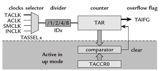
45 Configuring the Timer TACTL Timer A Control Register This register used to configure how the timer runs TACCTL0 Capture/Compare Control Register For enabling and disabling TimerA0 interrupt TACCR0 Capture/Compare Register This register holds the value YOU define to configure the timing 45
46 Timer A Block Diagram 46
47 47
48 Timer_A Registers 48
49 TACTL, Timer_A Control Register (PART 2) 49
50 Three items are given for each bit: Its position in the word, which should not be needed (use symbolic names instead). Its name, which is defined in the header file and should be known to the debugger; some bits are not used, which we show by a gray fill. The accessibility and initial condition of the bit; here they can all be read and written with the exception of TACLR, where the missing r indicates that there is no meaningful value to read. The (0) shows that each bit is cleared after a power-on reset (POR). 50
51 The user s guide goes on to describe the function of each bit or group of bits: Timer_A clock source select, TASSELx: There are four options for the clock: the internal SMCLK or ACLK or two external sources. TACLK (00), ACLK (01), SMCLK (10), or INCLK (11) Input divider, IDx: The frequency of the clock can be divided before it is applied to the timer, which extends the period of the counter. IDx bits determine the frequency division factor in the prescaler: 1 (00), 2 (01), 4 (10), and 8 (11) Mode control, MCx: The timer has four modes. By default it is off to save power. MCx bits set the operation mode: Halt (00), up mode (01), continuous mode (10), and up/down mode (11). Timer_A clear, TACLR: Setting this bit clears the counter, the divider, and the direction of the count (it can go both up and down in up/down mode). The bit is automatically cleared by the timer after use. It is usually a good idea to clear the counter whenever the timer is reconfigured to ensure that the first period has the expected duration. Timer_A interrupt enable, TAIE: Setting this bit enables interrupts when TAIFG becomes set.we do not use this here. Timer_A interrupt flag, TAIFG: This bit can be modified by the timer itself or by a program. It is raised (set) by the timer when the counter becomes 0. In continuous mode this happens when the value in TAR rolls over from 0xFFFF to 0x0000. An interrupt is also requested if TAIE has been set. The program must clear TAIFG so that the next overflow can be distinguished. 51
52 Continuous Mode Timer counts from 0 to 0xFFFF Fewer timing errors because timer never stops keeps counting up until it reaches 0xFFFF and rolls over to 0 and keeps going. 52
53 Modes of Operation: Continuous Mode 53
54 Continuous Mode If we have a period value in TACCR0 The ACTUAL VALUE of the timer does not matter only the RELOAD VALUE matters this controls the period of the interrupt. Interrupt DOES NOT OCCUR AT 0 OR 0xFFFF! Occurs when timer reaches current TACCR0 value! 54
55 Continuous Mode 55
56 Cont. Mode example The sub-main clock SMCLK runs at the same speed as MCLK by default, which is 800 KHz for example. If this were used to clock the timer directly, the period would be=2^16/800khz 0.08 s. We want about 0.5 s and therefore divide the frequency of the clock by 8 using IDx. IDx = 8 (11) This gives a delay of about 0.64 s, close enough. We use the simplest Continuous mode, in which TAR simply counts up through its full range of 0x0000 0xFFFF and repeats. This needs MCx =
57 Cont. Mode example // timrled1.c - toggles LEDs with period of about 1.3s // Poll free -running timer A with period of about 0.65s // Timer clock is SMCLK divided by 8, continuous mode // Olimex 1121STK, LED1,2 active low on P2.3,4 #include <io430x11x1.h> // Specific device // Pins for LEDs #define LED1 BIT3 #define LED2 BIT4 void main (void) { WDTCTL = WDTPW WDTHOLD; // Stop watchdog timer P2OUT = LED1; // Preload LED1 on, LED2 off P2DIR = LED1 LED2; // Set pins for LED1,2 to output TACTL = MC_2 ID_3 TASSEL_2 TACLR; // Set up and start Timer A // Continuous up mode, divide clock by 8, clock from SMCLK, clear timer for (;;) { // Loop forever while (TACTL_bit.TAIFG == 0) { // Wait for overflow } // doing nothing TACTL_bit.TAIFG = 0; // Clear overflow flag P2OUT ˆ= LED1 LED2; // Toggle LEDs } // Back around infinite loop } 57
58 Cont. Mode example More tasks could be added here, provided that they do not take longer than the period of the timer. The result is a paced loop, a straightforward structure for a program that carries out a sequence of tasks at regular intervals. Nowadays it would be unusual to pace the loop by polling the timer; instead the MCU would save energy by entering a low-power mode after it had completed the tasks and wait for the timer to wake it again. 58
59 Modes of Operation: Up Mode Timer counts UP from zero to TACCRO Interrupt occurs when timer goes back to zero Useful for periods other than 0xFFFF 59
60 Modes of Operation: Up Mode 60
61 Timer_A in Up Mode Finer control over the delay is obtained by using the timer in Up mode rather than continuous mode. The maximum desired value of the count is programmed into another register, TACCR0. In this mode TAR starts from 0 and counts up to the value in TACCR0, after which it returns to 0 and sets TAIFG. Thus the period is TACCR0+1 counts Here the clock has been divided down to 100 KHz so we need 50,000 counts for a delay of 0.5 s and should therefore store 49,999 in TACCR0. TACCR0 = 49999; // Upper limit of count for TAR TACTL = MC_1 ID_3 TASSEL_2 TACLR; // Set up and start Timer A // "Up to CCR0" mode, divide clock by 8, clock from SMCLK, clear timer 61
62 Random Light Display A pretty application of the delay is a random light show on the LEDs. Of course this is rather limited with only two LEDs but the principle can be applied to bigger displays. This again uses a delay set by the timer but requires a calculation for the next pattern to display 62
63 The circuit without the exclusive-or gate and its connections is a plain shift register. A D flip-flop simply reads the value on its D input at a clock transition and transfers it to its Q output. Thus the value in flip-flop 0 is transferred to flip-flop 1 after a clock transition. At the same time the value in flip-flop 1 is transferred to flip-flop 2 and so on. The pattern of bits simply shifts one place to the left in each clock cycle. An input is applied to the first flip-flop, 0. A pseudorandom sequence requires more complicated feedback. The simplest method, shown in the figure, is to take the feedback from an exclusive-or gate connected to the outputs of the last two stages. The counter must therefore be seeded with a nonzero value. The counter in Figure with N = 4 gives the sequence 0001, 0010, 0100, 1001, 0011, 0110, 1101, 1010, 0101, 1011, 0111, 1111, 1110, 1100, 1000 and repeat 63
64 Program to produce a pseudorandom bit sequence by simulating a shift register with feedback. // random1.c - pseudorandom sequence on LEDs Poll timer A in Up mode with period of about 0.5s // Timer clock is SMCLK divided by 8, up mode, p eriod Olimex 1121STK, LED1,2 active low on P2.3,4 // #include <io430x11x1.h> // Specific device #include <stdint.h> // For uint16_t #define LED1 BIT3// Pins for LEDs #define LED2 BIT4 // Parameters for shift register; length <= 15 (4 is good for testing) #define REGLENGTH 15 #define LASTMASK (( uint16_t) (BIT0 << REGLENGTH )) #define NEXTMASK (( uint16_t) (BIT0 << (REGLENGTH -1))) void main (void) { WDTCTL = WDTPW WDTHOLD; // Stop watchdog timer P2OUT = LED1 LED2; // Preload LEDs off P2DIR = LED1 LED2; // Set pins with LEDs to output TACCR0 = 49999; // Upper limit of count for TAR TACTL = MC_1 ID_3 TASSEL_2 TACLR; // Set up and start Timer A // "Up to CCR0" mode, divide clock by 8, clock from SMCLK, clear timer pattern = 1; for (;;) { // Loop forever while (TACTL_bit.TAIFG == 0) { // Wait for timer to overflow } // doing nothing TACTL_bit.TAIFG = 0; // Clear overflow flag P2OUT = pattern; // Update pattern (lower byte) pattern <<= 1; // Shift for next pattern // Mask two most significant bits, simulate XOR using switch, feed back switch (pattern & (LASTMASK NEXTMASK )) { case LASTMASK: case NEXTMASK: pattern = BIT0; // XOR gives 1 break; default: pattern &= BIT0; // XOR gives 0 break; } } } // Back around infinite loop 64
65 Modes of operation: Up Down mode Timer counts from 0 to TACCRO, then back down to 0 Used when timer period must be different from 0xFFFF and when pulse needs to be symmetric Good for driving motors (ON pulse to control speed) 65
66 Modes of operation: Up Down mode 66
67 Timer_A Interrupt Vectors 67
68 68
69 TACCTLx, Capture/Compare Control Register 69
70 Example 1 Continuous Mode Output pin P6.0 with toggle rate = 32768/(2*50) = 328Hz #include "include/include.h" #include "include/hardware.h" void main ( void ) { WDTCTL = WDTPW + WDTHOLD; // Stop WDT P6DIR = 0x01; // P6.0 output CCTL0 = CCIE; // CCR0 interrupt enabled CCR0 = 50; TACTL = TASSEL_1 + MC_2; // ACLK, contmode eint(); // Enable the global interrupt //or _BIS_SR(LPM0_bits + GIE); LPM0; // Enter low power mode or wait in a loop } // Timer_A TACCR0 interrupt vector handler interrupt (TIMERA0_VECTOR) TimerA_procedure(void){ P6OUT ^= 0x01; // Toggle P6.0 CCR0 += 50; // Add offset to CCR0 } 70
71 Example 2 Up Mode Output pin P6.0 with toggle rate = 32768/(2*50) = 328Hz #include "include/include.h" #include "include/hardware.h" void main ( void ) { WDTCTL = WDTPW + WDTHOLD; // Stop WDT P6DIR = 0x01; // P6.0 output CCTL0 = CCIE; // CCR0 interrupt enabled CCR0 = 50-1; TACTL = TASSEL_1 + MC_1; // ACLK, upmode _BIS_SR(LPM0_bits + GIE); // Enable the global interrupt and enter LPM0 } // Timer_A TACCR0 interrupt vector handler interrupt (TIMERA0_VECTOR) TimerA_procedure ( void ){ P6OUT ^= 0x01; // Toggle P6.0 } 71
Hacettepe University
 MSP430 Teaching Materials Week 5 FUNDAMENTALS OF INTERFACING AND TIMERS for MSP430 Hacettepe University Elements in Basic MCU Interface Power Source Feeds CPU and peripherals Clock Oscillators System synchronization
Timers and Clocks CS4101 嵌入式系統概論. Prof. Chung-Ta King. Department of Computer Science National Tsing Hua University, Taiwan
 CS4101 嵌入式系統概論 Timers and Clocks Prof. Chung-Ta King Department of Computer Science, Taiwan Materials from MSP430 Microcontroller Basics, John H. Davies, Newnes, 2008 Recall the Container Thermometer Container
CPE 323: MSP430 Timers
 CPE 323: MSP430 Timers Aleksandar Milenkovic Electrical and Computer Engineering The University of Alabama in Huntsville milenka@ece.uah.edu http://www.ece.uah.edu/~milenka Outline Watchdog Timer TimerA
CPE 325: Embedded Systems Laboratory Laboratory #7 Tutorial MSP430 Timers, Watchdog Timer, Timers A and B
 CPE 325: Embedded Systems Laboratory Laboratory #7 Tutorial MSP430 Timers, Watchdog Timer, Timers A and B Aleksandar Milenković Email: milenka@uah.edu Web: http://www.ece.uah.edu/~milenka Objective This
Lab 4: Interrupt. CS4101 Introduction to Embedded Systems. Prof. Chung-Ta King. Department of Computer Science National Tsing Hua University, Taiwan
 CS4101 Introduction to Embedded Systems Lab 4: Interrupt Prof. Chung-Ta King Department of Computer Science, Taiwan Introduction In this lab, we will learn interrupts of MSP430 Handling interrupts in MSP430
CPE/EE 421 Microcomputers
 CPE/EE 421 Microcomputers Instructor: Dr Aleksandar Milenkovic Lecture Note S13 *Material used is in part developed by Dr. D. Raskovic and Dr. E. Jovanov CPE/EE 421/521 Microcomputers 1 MSP430 Documentation
15.1 Timer_A Introduction
 Chapter 15 is a 16-bit timer/counter with multiple capture/compare registers. This chapter describes. This chapter describes the operation of the of the MSP430x4xx device family. Topic Page 15.1 Introduction.........................................
Timer Module Timer A. ReadMeFirst
 Timer Module Timer A ReadMeFirst Lab Folder Content 1) ReadMeFirst 2) TimerModule Lecture material 3) PinOutSummary 4) InterruptsVectorTable 5) Source code for screencast Interrupt Review Overview A Timer
The 16-bit timer/counter register, TAR, increments or decrements (depending on mode of operation) with each rising edge of the clock signal.
 with each rising edge of the clock signal.") Timer & Real Time Clock (RTC), PWM control, timing generation and measurements. Analog interfacing and data acquisition: ADC and Comparator in MSP430, data transfer using DMA. Case Study: MSP430 based
Timer & Real Time Clock (RTC), PWM control, timing generation and measurements. Analog interfacing and data acquisition: ADC and Comparator in MSP430, data transfer using DMA. Case Study: MSP430 based
// Conditions for 9600/4=2400 Baud SW UART, SMCLK = 1MHz #define Bitime_5 0x05*4 // ~ 0.5 bit length + small adjustment #define Bitime 13*4//0x0D
 /****************************************************************************** * * * 1. Device starts up in LPM3 + blinking LED to indicate device is alive * + Upon first button press, device transitions
IV B.Tech. I Sem (R13) ECE : Embedded Systems : UNIT -2 1 UNIT 2
 ECE : Embedded Systems : UNIT -2 1 UNIT 2") IV B.Tech. I Sem (R13) ECE : Embedded Systems : UNIT -2 1 UNIT 2 1. Block diagram of MSP430x5xx series micro-controller --------------------- 1 2. CPU architecture of MSP430x5xx ------------------------------------------------
IV B.Tech. I Sem (R13) ECE : Embedded Systems : UNIT -2 1 UNIT 2 1. Block diagram of MSP430x5xx series micro-controller --------------------- 1 2. CPU architecture of MSP430x5xx ------------------------------------------------
CPE/EE 421 Microcomputers
 CPE/EE 421 Microcomputers Instructor: Dr Aleksandar Milenkovic Lecture Note S11 MSP430 Documentation MSP430 home page (TI) www.ti.com/msp430 User s manual http://www.ece.uah.edu/~milenka/cpe421-05s/manuals/slau049c.pdf
What is an Interrupt?
 MSP430 Interrupts What is an Interrupt? Reaction to something in I/O (human, comm link) Usually asynchronous to processor activities interrupt handler or interrupt service routine (ISR) invoked to take
Alex Milenkovich 1. CPE/EE 421 Microcomputers. Course Administration. Review: Outline. Getting Started with EasyWeb2. Review: MSP bit RISC
 CPE/EE 421 Microcomputers Instructor: Dr Aleksandar Milenkovic Lecture Note S12 Course Administration Instructor: URL: TA: Labs: Test I: Text: Review: Today: Aleksandar Milenkovic milenka@ece.uah.edu www.ece.uah.edu/~milenka
Lab 4 Interrupts ReadMeFirst
 Lab 4 Interrupts ReadMeFirst Lab Folder Content 1) ReadMeFirst 2) Interrupt Vector Table 3) Pin out Summary Objectives Understand how interrupts work Learn to program Interrupt Service Routines in C Language
Lecture 5: MSP430 Interrupt
 ECE342 Intro. to Embedded Systems Lecture 5: MSP430 Interrupt Ying Tang Electrical and Computer Engineering Rowan University 1 How A Computer React to Inputs? Polling: the processor regularly looks at
MSP430 Interrupts. Change value of internal variable (count) Read a data value (sensor, receive) Write a data value (actuator, send)
 Read a data value (sensor, receive) Write a data value (actuator, send)") MSP430 Interrupts What is an Interrupt? Reaction to something in I/O (human, comm link) Usually asynchronous to processor activities interrupt handler or interrupt service routine (ISR) invoked to take
MSP430 Interrupts What is an Interrupt? Reaction to something in I/O (human, comm link) Usually asynchronous to processor activities interrupt handler or interrupt service routine (ISR) invoked to take
ECE2049: Embedded Computing in Engineering Design C Term Spring Lecture #11: More Clocks and Timers
 ECE2049: Embedded Computing in Engineering Design C Term Spring 2018 Lecture #11: More Clocks and Timers Reading for Today: Davie's Ch 8.3-8.4, 8.9-8.10, User's Guide Ch. 17 Reading for Next Class: User's
Interrupts CS4101 嵌入式系統概論. Prof. Chung-Ta King. Department of Computer Science National Tsing Hua University, Taiwan
 CS4101 嵌入式系統概論 Interrupts Prof. Chung-Ta King Department of Computer Science, Taiwan Materials from MSP430 Microcontroller Basics, John H. Davies, Newnes, 2008 Inside MSP430 (MSP430G2551) 1 Introduction
Texas Instruments Mixed Signal Processor Tutorial Abstract
 Texas Instruments Mixed Signal Processor Tutorial Abstract This tutorial goes through the process of writing a program that uses buttons to manipulate LEDs. One LED will be hard connected to the output
MSP430 Teaching Materials
 MSP430 Teaching Materials Lecture 5 Timers Description of clock signals Texas Instruments Incorporated University of Beira Interior (PT) Pedro Dinis Gaspar, António Espírito Santo, Bruno Ribeiro, Humberto
Embedded Systems. 3. Hardware Software Interface. Lothar Thiele. Computer Engineering and Networks Laboratory
 Embedded Systems 3. Hardware Software Interface Lothar Thiele Computer Engineering and Networks Laboratory Do you Remember? 3 2 3 3 High Level Physical View 3 4 High Level Physical View 3 5 What you will
Lab 1: I/O, timers, interrupts on the ez430-rf2500
 Lab 1: I/O, timers, interrupts on the ez430-rf2500 UC Berkeley - EE 290Q Thomas Watteyne January 25, 2010 1 The ez430-rf2500 and its Components 1.1 Crash Course on the MSP430f2274 The heart of this platform
ECSE-426. Microprocessor Systems. 2: Assembly + C 1
 ECSE-426 Microprocessor Systems 2: Assembly + C 1 Today s Lecture Theory Tutorial Appendix Multi-level machines Problem-oriented language layer Language Choice Machine Architecture Introduction to the
CPE 323 Introduction to Embedded Computer Systems: MSP430 System Architecture An Overview
 CPE 323 Introduction to Embedded Computer Systems: MSP430 System Architecture An Overview Aleksandar Milenkovic Electrical and Computer Engineering The University of Alabama in Huntsville milenka@ece.uah.edu
University of Texas at El Paso Electrical and Computer Engineering Department. EE 3176 Laboratory for Microprocessors I.
 University of Texas at El Paso Electrical and Computer Engineering Department EE 3176 Laboratory for Microprocessors I Fall 2016 LAB 04 Timer Interrupts Goals: Learn about Timer Interrupts. Learn how to
Getting Started with the MSP430 LaunchPad
 Getting Started with the MSP430 LaunchPad Student Guide and Lab Manual Revision 2.01 February 2012 Technical Training Organization Important Notice Important Notice Texas Instruments and its subsidiaries
MSP430. More on MSP430
 MSP430 More on MSP430 CodeComposer TI recently launched Code Composer Essentials v3. This IDE s latest version (version 3) supports all available MSP430 devices. The new features of CCE v3 include: - Free
2002 Mixed Signal Products SLAU056B
 User s Guide 22 Mixed Signal Products SLAU56B IMPORTANT NOTICE Texas Instruments Incorporated and its subsidiaries (TI) reserve the right to make corrections, modifications, enhancements, improvements,
Network Embedded Systems Sensor Networks Fall Hardware. Marcus Chang,
 Network Embedded Systems Sensor Networks Fall 2013 Hardware Marcus Chang, mchang@cs.jhu.edu 1 Embedded Systems Designed to do one or a few dedicated and/or specific functions Embedded as part of a complete
5xx Active & Low Power Mode Operation
 5xx Active & Low Power Mode Operation 38 Lab 2: ULP Operation Lab Goals Learn ULP Best Practices Learn & understand how to configure two key modules of the 5xx to achieve ultra-low power operation. Power
ECE PRACTICE EXAM #2 Clocks, Timers, and Digital I/O
 ECE2049 -- PRACTICE EXAM #2 Clocks, Timers, and Digital I/O Study HW3, Class Notes, Davies Ch 2.6, 5.8, 8, 9.2-3, 9.7, MSP43F5529 User's Guide Ch 5, 17, 28 Work all problems with your note sheet first
CPE 323 Introduction to Embedded Computer Systems: ADC12 and DAC12. Instructor: Dr Aleksandar Milenkovic Lecture Notes
 CPE 323 Introduction to Embedded Computer Systems: ADC12 and DAC12 Instructor: Dr Aleksandar Milenkovic Lecture Notes Outline MSP430: System Architecture ADC12 Module DAC12 Module CPE 323 2 ADC12 Introduction
Getting Started with the Texas Instruments ez430
 1 of 6 03.01.2009 01:33 HOME Running Your Code>> Getting Started with the Texas Instruments ez430 Working with the Workbench Software Step 1: Each program needs an associated project. The project includes
ECE2049: Embedded Computing in Engineering Design C Term Spring 2019 Lecture #22: MSP430F5529 Operating Mode & the WDT
 ECE2049: Embedded Computing in Engineering Design C Term Spring 2019 Lecture #22: MSP430F5529 Operating Mode & the WDT Reading for Today: User's Guide 1.4, Ch 16 Reading for Next Class: Review all since
Block diagram of processor (Harvard)
") Block diagram of processor (Harvard) Register transfer view of Harvard architecture Separate busses for instruction memory and data memory Example: PIC 16 load path OP REG AC 16 16 store path rd wr data
Block diagram of processor (Harvard) Register transfer view of Harvard architecture Separate busses for instruction memory and data memory Example: PIC 16 load path OP REG AC 16 16 store path rd wr data
2.996/6.971 Biomedical Devices Design Laboratory Lecture 6: Microprocessors II
 2.996/6.971 Biomedical Devices Design Laboratory Lecture 6: Microprocessors II Instructor: Dr. Hong Ma Oct. 1, 2007 Structure of MSP430 Program 1. Declarations 2. main() 1. Watch-dog timer servicing 2.
Copyright 2015 by Stephen A. Zajac & Gregory M. Wierzba. All rights reserved..spring 2015.
 Copyright 2015 by Stephen A. Zajac & Gregory M. Wierzba. All rights reserved..spring 2015. Copyright 2015 by Stephen A. Zajac & Gregory M. Wierzba. All rights reserved..spring 2015. Copyright 2015 by Stephen
2006 Mixed Signal Products SLAU049F
 User s Guide 2006 Mixed Signal Products SLAU049F Related Documentation From Texas Instruments Preface About This Manual This manual discusses modules and peripherals of the MSP430x1xx family of devices.
CPE/EE 421 Microcomputers: The MSP430 Introduction
 Outline CPE/EE 421 Microcomputers: The MSP430 Introduction Instructor: Dr Aleksandar Milenkovic Lecture Notes MSP430: An Introduction The MSP430 family Technology Roadmap Typical Applications The MSP430
Interfacing CMA3000-D01 to an MSP430 ultra low-power microcontroller
 Interfacing CMA3000-D01 to an MSP430 ultra low-power microcontroller 1 INTRODUCTION The objective of this document is to show how to set up SPI/I2C communication between VTI Technologies CMA3000-D01 digital
Hello, and welcome to this presentation of the STM32 Real- Time Clock. It covers the main features of this peripheral, which is used to provide a
 Hello, and welcome to this presentation of the STM32 Real- Time Clock. It covers the main features of this peripheral, which is used to provide a very accurate time base. 1 The RTC peripheral features
Network Embedded Systems Sensor Networks. Tips and Tricks. Marcus Chang,
 Network Embedded Systems Sensor Networks Tips and Tricks Marcus Chang, mchang@cs.jhu.edu 1 Project Part 3 PC --UART--> Telosb --radio--> Telosb Reliable communication and storage Data corruption Missing
Getting Started with the MSP430 LaunchPad
 Getting Started with the MSP430 LaunchPad Student Guide and Lab Manual Revision 1.0 October 2010 Technical Training Organization Important Notice Important Notice Texas Instruments and its subsidiaries
Understanding the new '5xx Integrated Power Management Module (PMM) Stefan Schauer
 Stefan Schauer") Understanding the new '5xx Integrated Power Management Module (PMM) Stefan Schauer 6/5/2008 1 Agenda Introduction into the PMM System Technical Data, specified Values Software controlled PMM configuration
Understanding the new '5xx Integrated Power Management Module (PMM) Stefan Schauer 6/5/2008 1 Agenda Introduction into the PMM System Technical Data, specified Values Software controlled PMM configuration
M68HC08 Microcontroller The MC68HC908GP32. General Description. MCU Block Diagram CPU08 1
 M68HC08 Microcontroller The MC68HC908GP32 Babak Kia Adjunct Professor Boston University College of Engineering Email: bkia -at- bu.edu ENG SC757 - Advanced Microprocessor Design General Description The
 Distributed by: www.jameco.com 1-800-831-4242 The content and copyrights of the attached material are the property of its owner. MSP430F11x2/12x2 Device Erratasheet Current Version Devices MSP430F1122
Reading: Davies , 8.3-4, , MSP430x55xx User's Guide Ch. 5,17
 ECE2049 Homework #3 Clocks & Timers (Due Tuesday 9/19/17 At the BEGINNING of class) Your homework should be neat and professional looking. You will loose points if your HW is not properly submitted (by
Lecture 2 MSP430 Architecture. Atul Lele Ramakrishna Reddy
 Lecture 2 MSP430 Architecture Atul Lele Ramakrishna Reddy About me Education B.E. in Electronics and Telecommunication, PICT, Pune (2000) Professional experience Working with Texas Instruments India Pvt
2006 Mixed Signal Products SLAU049F
 User s Guide 2006 Mixed Signal Products SLAU049F IMPORTANT NOTICE Texas Instruments Incorporated and its subsidiaries (TI) reserve the right to make corrections, modifications, enhancements, improvements,
SECTION 5 RESETS AND INTERRUPTS
 SECTION RESETS AND INTERRUPTS Resets and interrupt operations load the program counter with a vector that points to a new location from which instructions are to be fetched. A reset immediately stops execution
University of Texas at El Paso Electrical and Computer Engineering Department. EE 3176 Laboratory for Microprocessors I.
 University of Texas at El Paso Electrical and Computer Engineering Department EE 3176 Laboratory for Microprocessors I Fall 2016 LAB 03 Low Power Mode and Port Interrupts Goals: Bonus: Pre Lab Questions:
3. The MC6802 MICROPROCESSOR
 3. The MC6802 MICROPROCESSOR This chapter provides hardware detail on the Motorola MC6802 microprocessor to enable the reader to use of this microprocessor. It is important to learn the operation and interfacing
Towards Hard Real-time Performance in a Highly Asynchronous Multitasking MSP430 Application Andrew E. Kalman, Ph.D.
 Towards Hard Real-time Performance in a Highly Asynchronous Multitasking MSP430 Application Andrew E. Kalman, Ph.D. Slide 1 Outline Overview Part I: TimerA does PWM Part II: TimerB drives a Stepper Part
2006 Mixed Signal Products SLAU144B
 User s Guide 2006 Mixed Signal Products SLAU144B IMPORTANT NOTICE Texas Instruments Incorporated and its subsidiaries (TI) reserve the right to make corrections, modifications, enhancements, improvements,
Interrupts, Low Power Modes
 Interrupts, Low Power Modes Registers Status Register Interrupts (Chapter 6 in text) A computer has 2 basic ways to react to inputs: 1) polling: The processor regularly looks at the input and reacts as
TAxCTL Register
 Timer_A Registers 17.3.1 TAxCTL Register Timer_Ax Control Register Figure 17-16. TAxCTL Register Reserved TASSEL ID MC Reserved TACLR TAIE TAIFG rw-(0) rw-(0) rw-(0) rw-(0) rw-(0) w-(0) rw-(0) rw-(0) 15-10
Module Introduction. PURPOSE: The intent of this module is to explain MCU processing of reset and interrupt exception events.
 Module Introduction PURPOSE: The intent of this module is to explain MCU processing of reset and interrupt exception events. OBJECTIVES: - Describe the difference between resets and interrupts. - Identify
Week 4: Embedded Programming Using C
 Week 4: Embedded Programming Using C The C language evolved from BCPL (1967) and B (1970), both of which were type-less languages. C was developed as a strongly-typed language by DennisRitchie in 1972,
Understanding the basic building blocks of a microcontroller device in general. Knows the terminologies like embedded and external memory devices,
 Understanding the basic building blocks of a microcontroller device in general. Knows the terminologies like embedded and external memory devices, CISC and RISC processors etc. Knows the architecture and
Section 10. Power-Saving Features
 Section 10. Power-Saving Features HIGHLIGHTS This section of the manual contains the following major topics: 10.1 Introduction... 10-2 10.2 Microcontroller Clock Manipulation... 10-2 10.3 Instruction-Based
Microcontrollers. vs Microprocessors
 Microcontrollers vs Microprocessors Microprocessors Arbitrary computations Arbitrary control structures Arbitrary data structures Specify function at high-level and use compilers and debuggers Composed
MSP430x43x1, MSP430x43x, MSP430x44x1, MSP430x44x MIXED SIGNAL MICROCONTROLLER
 Low Supply-Voltage Range,.8 V to 3.6 V Ultralow-Power Consumption: Active Mode: 28 µa at MHz, 2.2 V Standby Mode:. µa Off Mode (RAM Retention):. µa Five Power Saving Modes Wake-Up From Standby Mode in
Chapter 1: Basics of Microprocessor [08 M]
![Chapter 1: Basics of Microprocessor [08 M]](/thumbs/77/75860546.jpg "Chapter 1: Basics of Microprocessor [08 M]") Microprocessor: Chapter 1: Basics of Microprocessor [08 M] It is a semiconductor device consisting of electronic logic circuits manufactured by using either a Large scale (LSI) or Very Large Scale (VLSI)
Microprocessor: Chapter 1: Basics of Microprocessor [08 M] It is a semiconductor device consisting of electronic logic circuits manufactured by using either a Large scale (LSI) or Very Large Scale (VLSI)
MSP430F20xx Device Erratasheet
 Errata MSP430F20xx Device Erratasheet 1 Current Version Devices Rev: BCL12 CPU4 FLASH16 SDA3 TA12 TA16 TA22 USI4 USI5 XOSC5 XOSC8 MSP430F2001 D ü ü ü ü ü ü ü ü MSP430F2011 D ü ü ü ü ü ü ü ü MSP430F2002
Interfacing CMR3000-D01 to an MSP430 ultra low-power microcontroller
 Interfacing CMR3000-D01 to an MSP430 ultra low-power microcontroller 1 INTRODUCTION The objective of this document is to show how to set up SPI/I2C communication between VTI Technologies CMR3000-D01 digital
MSP430x2xx Family. User s Guide Extract Mixed Signal Products SLAU167
 MSP430x2xx Family User s Guide Extract 2005 Mixed Signal Products SLAU167 IMPORTANT NOTICE Texas Instruments Incorporated and its subsidiaries (TI) reserve the right to make corrections, modifications,
Reading: Davies , 8.3-4, , MSP430x55xx User's Guide Ch. 5,17, MSP430F5529 Launchpad User's Guide
 ECE2049 Homework #3 Clocks & Timers (Due Thursday 2/8/18 At the BEGINNING of class) Your homework should be neat and professional looking. You will loose points if your HW is not properly submitted (by
Wireless Sensor Networks (WSN)
") Wireless Sensor Networks (WSN) Operating Systems M. Schölzel Operating System Tasks Traditional OS Controlling and protecting access to resources (memory, I/O, computing resources) managing their allocation
Wireless Sensor Networks (WSN) Operating Systems M. Schölzel Operating System Tasks Traditional OS Controlling and protecting access to resources (memory, I/O, computing resources) managing their allocation
ECGR 4101/5101, Fall 2016: Lab 1 First Embedded Systems Project Learning Objectives:
 ECGR 4101/5101, Fall 2016: Lab 1 First Embedded Systems Project Learning Objectives: This lab will introduce basic embedded systems programming concepts by familiarizing the user with an embedded programming
Course Introduction. Purpose: Objectives: Content: 27 pages 4 questions. Learning Time: 20 minutes
 Course Introduction Purpose: This course provides an overview of the Direct Memory Access Controller and the Interrupt Controller on the SH-2 and SH-2A families of 32-bit RISC microcontrollers, which are
Course Introduction. 2009, Renesas Technology America, Inc., All Rights Reserved
 Course Introduction Purpose This course provides an introduction to the peripheral functions built into R8C Tiny series microcontrollers (MCUs). Objective Learn about the features and operation of the
Section 8. Reset HIGHLIGHTS. Reset. This section of the manual contains the following major topics:
 Section 8. HIGHLIGHTS This section of the manual contains the following major topics: 8.1 Introduction... 8-2 8.2 Control Registers...8-3 8.3 System...8-6 8.4 Using the RCON Status Bits... 8-11 8.5 Device
CPE 325: Embedded Systems Laboratory Laboratory #11 Tutorial Analog-to-Digital Converter and Digital-to-Analog Converter
 CPE 325: Embedded Systems Laboratory Laboratory #11 Tutorial Analog-to-Digital Converter and Digital-to-Analog Converter Aleksandar Milenković Email: milenka@uah.edu Web: http://www.ece.uah.edu/~milenka
1. Internal Architecture of 8085 Microprocessor
 1. Internal Architecture of 8085 Microprocessor Control Unit Generates signals within up to carry out the instruction, which has been decoded. In reality causes certain connections between blocks of the
Chapter 1 MSP430 Microcontroller Family
 Chapter 1 1-1 Introduction 1.1 Introduction The MSP430 is a 16-bit microcontroller that has a number of special features not commonly available with other microcontrollers: Complete system on-a-chip includes
Section 10. Watchdog Timer and Power Saving Modes
 Section 10. Watchdog Timer and Power Saving Modes HIGHLIGHTS This section of the manual contains the following topics: 10.1 Introduction... 10-2 10.2 Power Saving Modes... 10-2 10.3 Sleep Mode...10-2 10.4
Hacettepe University
 www.msp430.ubi.pt MSP430 Teaching Materials Introductory Overview Week2 Hacettepe University Outline Microcontrollers Versus Microprocessors Central Processing Unit System Buses Memory Organization I/O
CPE/EE 323 Introduction to Embedded Computer Systems Homework V
 CPE/EE 323 Introduction to Embedded Computer Systems Homework V 1(15) 2(15) 3(25) 4(25) 5(20) Total Problem #1 (15 points) Power, Low power systems A sensor platform features a microcontroller, a sensor,
Introduction to Embedded Systems
 Stefan Kowalewski, 4. November 25 Introduction to Embedded Systems Part 2: Microcontrollers. Basics 2. Structure/elements 3. Digital I/O 4. Interrupts 5. Timers/Counters Introduction to Embedded Systems
AVR XMEGA Product Line Introduction AVR XMEGA TM. Product Introduction.
 AVR XMEGA TM Product Introduction 32-bit AVR UC3 AVR Flash Microcontrollers The highest performance AVR in the world 8/16-bit AVR XMEGA Peripheral Performance 8-bit megaavr The world s most successful
Fall. Accelerometer RGB LED control Vishal Shah Rebel Sequeira Pratiksha Patil Pranali Dhuru Chris Blackden. George Mason University
 Fall 13 Accelerometer RGB LED control Vishal Shah Rebel Sequeira Pratiksha Patil Pranali Dhuru Chris Blackden George Mason University Introduction The ECE 511 course gave us the opportunity to team up
Raystar Microelectronics Technology Inc.
 Product Features Product Description Wide operating voltage 2.5V to 5.5V Self-contained battery and crystal in Module Supports I 2 C-Bus's high speed mode (400 khz) Includes time (Hour/Minute/Second) and
6. General purpose Input/Output
 Chapter 6 6. General purpose Input/Output This chapter starts with a description of one of the simplest integrated peripherals of the MSP430 the General Purpose 8-bit Input Output (GPIO). The Input/Output
MN101E50 Series. 8-bit Single-chip Microcontroller
 8-bit Single-chip Microcontroller Overview The MN101E series of 8-bit single-chip microcomputers (the memory expansion version of MN101C series) incorporate multiple types of peripheral functions. This
EE6008-Microcontroller Based System Design Department Of EEE/ DCE
 UNIT- II INTERRUPTS AND TIMERS PART A 1. What are the interrupts available in PIC? (Jan 14) Interrupt Source Enabled by Completion Status External interrupt from INT INTE = 1 INTF = 1 TMR0 interrupt T0IE
DP8571A Timer Clock Peripheral (TCP)
") DP8571A Timer Clock Peripheral (TCP) General Description The DP8571A is intended for use in microprocessor based systems where information is required for multi-tasking data logging or general time of
DP8571A Timer Clock Peripheral (TCP) General Description The DP8571A is intended for use in microprocessor based systems where information is required for multi-tasking data logging or general time of
Designing for Ultra-Low Power with MSP430
 Designing for Ultra-Low Power with MSP430 Christian Hernitscheck MSP430 FAE Europe Texas Instruments 2006 Texas Instruments Inc, Slide 1 Agenda Introduction to Ultra-Low Power Looking for Ultra-Low Power
Architecture of Computers and Parallel Systems Part 6: Microcomputers
 Architecture of Computers and Parallel Systems Part 6: Microcomputers Ing. Petr Olivka petr.olivka@vsb.cz Department of Computer Science FEI VSB-TUO Architecture of Computers and Parallel Systems Part
HC12 Built-In Hardware
 HC12 Built-In Hardware The HC12 has a number of useful pieces of hardware built into the chip. Different versions of the HC12 have slightly different pieces of hardware. We are using the MC68HC912B32 chip
CENG-336 Introduction to Embedded Systems Development. Timers
 CENG-336 Introduction to Embedded Systems Development Timers Definitions A counter counts (possibly asynchronous) input pulses from an external signal A timer counts pulses of a fixed, known frequency
ZigBee Compliant Platform 2.4G RF Low Power Transceiver Module for IEEE Standard. DATA SHEET Version B
 ZMD400-A01 ZigBee Compliant Platform 2.4G RF Low Power Transceiver Module for IEEE 802.15.4 Standard DATA SHEET Version B Quan International Co., Ltd., ZMD400 Features Fully compliant 802.15.4 Standard
UNIT V MICRO CONTROLLER PROGRAMMING & APPLICATIONS TWO MARKS. 3.Give any two differences between microprocessor and micro controller.
 UNIT V -8051 MICRO CONTROLLER PROGRAMMING & APPLICATIONS TWO MARKS 1. What is micro controller? Micro controller is a microprocessor with limited number of RAM, ROM, I/O ports and timer on a single chip
e-pg Pathshala Subject : Computer Science Paper: Embedded System Module: 8051 Architecture Module No: CS/ES/5 Quadrant 1 e-text
 e-pg Pathshala Subject : Computer Science Paper: Embedded System Module: 8051 Architecture Module No: CS/ES/5 Quadrant 1 e-text In this lecture the detailed architecture of 8051 controller, register bank,
2. List the five interrupt pins available in INTR, TRAP, RST 7.5, RST 6.5, RST 5.5.
 DHANALAKSHMI COLLEGE OF ENGINEERING DEPARTMENT OF ELECTRICAL AND ELECTRONICS ENGINEERING EE6502- MICROPROCESSORS AND MICROCONTROLLERS UNIT I: 8085 PROCESSOR PART A 1. What is the need for ALE signal in
1.Overview of X7083/X7043/X7023
 1.Overview of X7083/X7043/X7023 11 Introduction X7083/X7043/X7023 is an LSI that generates a pulse for controlling the speed and positioning of pulse train inputtype servo motors and stepping motors. X7083
Frequently Asked Questions
 Product Name: System Basis Chips (SBCs) Date: September 2014 Application: Automotive ECUs Datasheet: TLE9263-3QX rev. 1.1 Contact Person: Norbert Ulshoefer/Antonio Monetti/Shinichiro Tatsu Mid-Range SBC
Microprocessors & Interfacing
 Lecture Overview Microprocessors & Interfacing Interrupts (I) Lecturer : Dr. Annie Guo Introduction to Interrupts Interrupt system specifications Multiple sources of interrupts Interrupt priorities Interrupts
Master Thesis. Sub-Gigahertz Wireless Sensors For Monitoring Of Food Transportation. Faisal Ali Khan. Submitted by. Universität Bremen
 Universität Bremen Fachbereich Physik, Elektro- und Informationstechnik Institut für Mikrosensoren, -Aktoren Und -Systeme (IMSAS) Master Thesis Sub-Gigahertz Wireless Sensors For Monitoring Of Food Transportation
PIC Microcontroller Introduction
 PIC Microcontroller Introduction The real name of this microcontroller is PICmicro (Peripheral Interface Controller), but it is better known as PIC. Its first ancestor was designed in 1975 by General Instruments.