The 16-bit timer/counter register, TAR, increments or decrements (depending on mode of operation) with each rising edge of the clock signal.
|
|
|
- Matthew Henderson
- 5 years ago
- Views:
Transcription

1 Timer & Real Time Clock (RTC), PWM control, timing generation and measurements. Analog interfacing and data acquisition: ADC and Comparator in MSP430, data transfer using DMA. Case Study: MSP430 based embedded system application using ADC & PWM demonstrating peripheral intelligence. Remote Controller of Air Conditioner Using MSP430. Timer Timer_A is a 16-bit timer/counter with multiple capture/compare registers. Timer_A is a 16-bit timer/counter with up to seven capture/compare registers. Timer_A can support multiple capture/compares, PWM outputs, and interval timing. Timer_A also has extensive interrupt capabilities. Interrupts may be generated from the counter on overflow conditions and from each of the capture/compare registers. Timer_A features include: Asynchronous 16-bit timer/counter with four operating modes Selectable and configurable clock source Up to seven configurable capture/compare registers Configurable outputs with PWM capability Asynchronous input and output latching Interrupt vector register for fast decoding of all Timer_A interrupts
2 The 16-bit timer/counter register, TAR, increments or decrements (depending on mode of operation) with each rising edge of the clock signal. TAR can be read or written with software. Additionally, the timer can generate an interrupt when it overflows. TAR may be cleared by setting the TACLR bit. Setting TACLR also clears the clock divider and count direction for up/down mode. Clock Source Select and Divider The timer clock TACLK can be sourced from ACLK, SMCLK, or externally via TACLK. The clock source is selected with the TASSELx bits. The selected clock source may be passed directly to the timer or divided by 2, 4, or 8, using the IDx bits The selected clock source can be further divided by 2, 3, 4, 5, 6, 7, or 8 using the IDEXx bits.the TACLK dividers are reset when TACLR is set. The timer may be started, or restarted in the following ways: The timer counts when MCx > 0 and the clock source is active. When the timer mode is either up or up/down, the timer may be stopped by writing 0 to TACCR0. The timer may then be restarted by writing a nonzero value to TACCR0. In this scenario, the timer starts incrementing in the up direction from zero.

3 Up Mode The up mode is used if the timer period must be different from 0FFFFh counts. The timer repeatedly counts up to the value of compare register TACCR0, which defines the period, as shown in Figure. The number of timer counts in the period is TACCR0+1. When the timer value equals TACCR0 the timer restarts counting from zero. If up mode is selected when the timer value is greater than TACCR0, the timer immediately restarts counting from zero The TACCR0 CCIFG interrupt flag is set when the timer counts to the TACCR0 value. The TAIFG interrupt flag is set when the timer counts from TACCR0 to zero. Continuous Mode: In the continuous mode, the Continuous Mode timer repeatedly counts up to 0FFFFh and restarts from zero as shown in Figure. The capture/compare register TACCR0 works the same way as the other capture/compare registers. The TAIFG interrupt flag is set when the timer counts from 0FFFFh to zero
4 Use of the Continuous Mode The continuous mode can be used to generate independent time intervals and output frequencies. Each time an interval is completed, an interrupt is generated. The next time interval is added to the TACCRx register in the interrupt service routine. Figure shows two separate time intervals t0 and t1 being added to the capture/compare registers. In this usage, the time interval is controlled by hardware, not software, without impact from interrupt latency. Up to n (Timer_An), where n = 0 to 7, independent time intervals or output frequencies can be generated using capture/compare registers. Time intervals can be produced with other modes as well, where TACCR0 is used as the period register. Their handling is more complex since the sum of the old TACCRx data and the new period can be higher than the TACCR0 value. When the previous TACCRx value plus tx is greater than the TACCR0 data, the TACCR0 value must be subtracted to obtain the correct time interval. Up/Down Mode The up/down mode is used if the timer period must be different from 0FFFFh counts, and if symmetrical pulse generation is needed. The timer repeatedly counts up to the value of compare register TACCR0 and back down to zero, The count direction is latched. This allows the timer to be stopped and then restarted in the same direction it was counting before it was stopped. If this is not desired, the TACLR bit must be set to clear the direction. The TACLR bit also clears the TAR value and the TACLK divider. In up/down mode, the TACCR0 CCIFG interrupt flag and the TAIFG interrupt flag are set only once during a period, separated by 1/2 the timer period. The TACCR0 CCIFG interrupt flag is set when the timer counts from TACCR0-1 to TACCR0, and TAIFG is set when the timer completes counting down from 0001h to 0000h.
5 Capture/Compare Blocks: Three or five identical capture/compare blocks, TACCRx, are present in Timer_A. Any of the blocks may be used to capture the timer data, or to generate time intervals. Capture Mode The capture mode is selected when CAP = 1. Capture mode is used to record time events. It can be used for speed computations or time measurements. The capture inputs CCIxA and CCIxB are connected to external pins or internal signals and are selected with the CCISx bits. The CMx bits select the capture edge of the input signal as rising, falling, or both. A capture occurs on the selected edge of the input signal. If a capture occurs: The timer value is copied into the TACCRx register The interrupt flag CCIFG is set The input signal level can be read at any time via the CCI bit. MSP430x5xx family devices may have different signals connected to CCIxA and CCIxB. Refer to the device-specific data sheet for the connections of these signals. The capture signal can be asynchronous to the timer clock and cause a race condition. Setting the SCS bit will synchronize the capture with the next timer clock. Setting the SCS bit to synchronize the capture signal with the timer clock is recommended. Overflow logic is provided in each capture/compare register to indicate if a second capture was performed before the value from the first capture was read. Bit COV is set
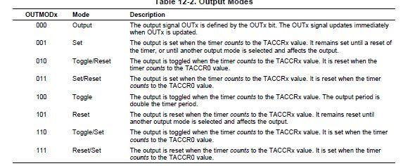
6 Capture Mode: Captures can be initiated by software. The CMx bits can be set for capture on both edges. Software then sets CCIS1 = 1 and toggles bit CCIS0 to switch the capture signal between VCC and GND, initiating a capture each time CCIS0 changes state: MOV #CAP+SCS+CCIS1+CM_3,&TACCTLx ; Setup TACCTLx XOR #CCIS0,&TACCTLx ; TACCTLx = TAR Compare Mode The compare mode is selected when CAP = 0. The compare mode is used to generate PWM output signals or interrupts at specific time intervals. When TAR counts to the value in a TACCRx: Interrupt flag CCIFG is set Internal signal EQUx = 1 EQUx affects the output according to the output mode The input signal CCI is latched into SCCI Output Unit: Each capture/compare block contains an output unit. The output unit is used to generate output signals such as PWM signals. Each output unit has eight operating modes that generate signals based on the EQU0 and EQUx signals. Output Modes The output modes are defined by the OUTMODx bits and are described in Table. The OUTx signal is changed with the rising edge of the timer clock for all modes except mode 0. Output modes 2, 3, 6, and 7 are not useful for output unit 0 because EQUx = EQU0.
7
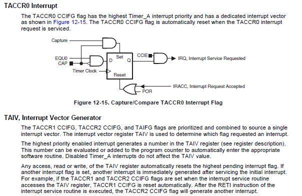
8 Timer_A Interrupts Two interrupt vectors are associated with the 16-bit Timer_A module: TACCR0 interrupt vector for TACCR0 CCIFG TAIV interrupt vector for all other CCIFG flags and TAIFG In capture mode any CCIFG flag is set when a timer value is captured in the associated TACCRx register. In compare mode, any CCIFG flag is set if TAR counts to the associated TACCRx value. Software may also set or clear any CCIFG flag. All CCIFG flags request an interrupt when their corresponding CCIE bit and the GIE bit are set.
9
10 Timer B Timer_B is a 16-bit timer/counter with three or seven capture/compare registers. Timer_B can support multiple capture/compares, PWM outputs, and interval timing. Timer_B also has extensive interrupt capabilities. Interrupts may be generated from the counter on overflow conditions and from each of the capture/compare registers. Timer_B features include : Asynchronous 16-bit timer/counter with four operating modes and four selectable lengths Selectable and configurable clock source

11 Up to seven configurable capture/compare registers Configurable outputs with PWM capability Double-buffered compare latches with synchronized loading Interrupt vector register for fast decoding of all Timer_B interrupts Timer_B is identical to Timer_A with the following exceptions: The length of Timer_B is programmable to be 8, 10, 12, or 16 bits. Timer_B TBCCRx registers are double-buffered and can be grouped. All Timer_B outputs can be put into a high-impedance state. The SCCI bit function is not implemented in Timer_B.

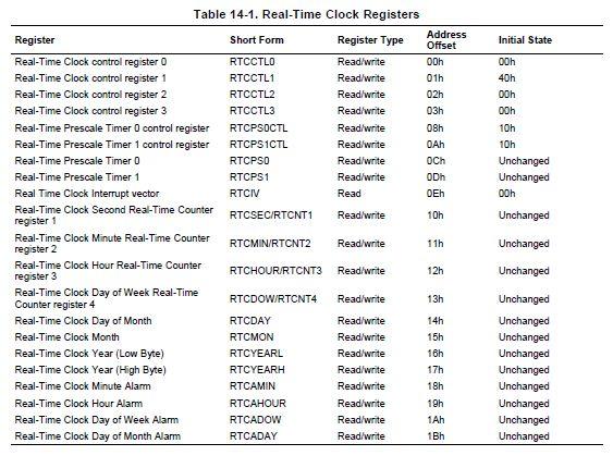
12 Real Time Clock: The Real-Time Clock module provides a clock with calendar that can also be configured as a general purpose counter. Real-Time Clock features include: Configurable for Real-Time Clock mode or general purpose counter Provides seconds, minutes, hours, day of week, day of month, month and year in calender mode. Interrupt capability. Selectable BCD or binary format in Real-Time Clock mode Programmable alarms in Real-Time Clock mode Calibration logic for time offset correction in Real-Time clock mode
13 The Real-Time Clock module can be configured as a real-time clock with calendar function or as a 32-bit general purpose counter with the RTCMODE bit. Counter mode Counter mode is selected when RTCMODE is reset. In this mode, a 32-bit counter is provided that isdirectly accessible by software. Switching from calendar mode to counter mode resets the count value (RTCNT1, RTCNT2, RTCNT3, RTCNT4), as well as, the prescale counters (RT0PS, RT1PS). The clock to increment the counter can be sourced from ACLK, SMCLK, or prescaled versions of ACLK or SMCLK. Prescaled versions of ACLK or SMCLK are sourced from the prescale dividers, RT0PS and RT1PS. RT0PS and RT1PS output /2, /4, /8, 16, /32, /64, /128, /256 versions of ACLK and SMCLK, respectively. The output of RT0PS can be cascaded with RT1PS. The cascaded output can be used as a clock source input to the 32-bit counter.
14 Four individual 8-bit counters are cascaded to provide the 32-bit counter. This provides 8-bit, 16-bit, 24-bit, or 32-bit overflow intervals of the counter clock. The RTCTEV bits select the respective trigger event. An RTCTEV event can trigger an interrupt by setting the RTCTEVIE bit. Each counter RTCNT1 through RTCNT4 is individually accessible and may be written to. RT0PS and RT1PS can be configured as two 8-bit counters or cascaded into a single 16-bit counter. RT0PS and RT1PS can be halted on an individual basis by setting their respective RT0PSHOLD and RT1PSHOLD bits. When RT0PS is cascaded with RT1PS, setting RT0PSHOLD will cause both RT0PS and RT1PS to be halted. The 32-bit counter can be halted several ways depending on the configuration. If the 32-bit counter is sourced directly from ACLK or SMCLK, it can be halted by setting RTCHOLD. If it is sourced from the output of RT1PS, it can be halted by setting RT1PSHOLD or RTCHOLD. Finally, if it is sourced from the cascaded outputs of RT0PS and RT1PS, it can be halted by setting RT0PSHOLD, RT1PSHOLD, or RTCHOLD. Calendar mode Calendar mode is selected when RTCMODE is set. In calendar mode, the Real-Time Clock module provides seconds, minutes, hours, day of week, day of month, month, and year in selectable BCD or hexadecimal format. The calendar includes a leap year algorithm that considers all years evenly divisible by 4 as leap years. This algorithm is accurate from the year 1901 through The prescale dividers, RT0PS and RT1PS are automatically configured to provide a one second clock interval for the Real-Time Clock. RT0PS is sourced from ACLK. ACLK must be set to Hz, nominal for proper Real-Time Clock calendar operation. RT1PS is cascaded with the output ACLK/256 of RT0PS. The Real-Time Clock is sourced with the /128 output of RT1PS, thereby providing the required one second interval. Switching from counter to calendar mode clears the seconds, minutes, hours, day-of-week, and year counts and sets day-of-month and month counts to 1. In addition, the RT0PS and RT1PS are cleared. When RTCBCD = 1, BCD format is selected for the calendar registers. The format must be selected before the time is set. Changing the state of RTCBCD clears the seconds, minutes, hours, day-of-week, and year counts and sets day-of-month and month counts to 1. In addition, RT0PS and RT1PS are cleared. In calendar mode, the RT0SSEL, RT1SSEL, RT0PSDIV, RT1PSDIV, RT0PSHOLD, RT1PSHOLD, and RTCSSEL bits are do not care. Setting RTCHOLD halts the real-time counters and prescale counters, RT0PS and RT1PS. Real-Time Clock and Prescale Dividers The prescale dividers, RT0PS and RT1PS are automatically configured to provide a one second clock interval for the Real-Time Clock. RT0PS is sourced from ACLK. ACLK must be set to Hz, nominal for proper Real-Time Clock calendar operation. RT1PS is cascaded with the output ACLK/256 of RT0PS. The Real-Time Clock is sourced with the /128 output of RT1PS, thereby providing the required one second interval. Switching from counter to calendar mode clears the seconds, minutes, hours, day-of-week, and year counts and sets day-of-month and month counts to 1. In addition, the RT0PS and RT1PS are cleared. When RTCBCD = 1, BCD format is selected for the calendar registers. The format must be selected before the time is set. Changing the state of RTCBCD clears the seconds, minutes,
15 hours, day-of-week, and year counts and sets day-of-month and month counts to 1. In addition, RT0PS and RT1PS are cleared. In calendar mode, the RT0SSEL, RT1SSEL, RT0PSDIV, RT1PSDIV, RT0PSHOLD, RT1PSHOLD, and RTCSSEL bits are do not care. Setting RTCHOLD halts the real-time counters and prescale counters, RT0PS and RT1PS. Real-Time Clock Alarm Function The Real-Time Clock module provides for a flexible alarm system. There is a single, user programmable alarm that can be programmed based on the settings contained in the alarm registers for minutes, hours, day of week, and day of month. The user programmable alarm function is only available in calendar mode of operation. Each alarm register contains an alarm enable bit, AE that can be used to enable the respective alarm register. By setting AE bits of the various alarm registers, a variety of alarm events can be generated. For example, a user wishes to set an alarm every hour at 15 minutes past the hour i.e. 00:15:00, 01:15:00, 02:15:00, etc. This is possible by setting RTCAMIN to 15. By setting the AE bit of the RTCAMIN, and clearing all other AE bits of the alarm registers, the alarm will be enabled. When enabled, the AF will be set when the count transitions from 00:14:59 to 00:15:00, 01:14:59 to 01:15:00, 02:14:59 to 02:15:00, etc. For example, a user wishes to set an alarm every day at 04:00:00. This is possible by setting RTCAHOUR to 4. By setting the AE bit of the RTCHOUR, and clearing all other AE bits of the alarm registers, the alarm will be enabled. When enabled, the AF will be set when the count transitions from 03:59:59 to 04:00:00. For example, a user wishes to set an alarm for 06:30:00. RTCAHOUR would be set to 6 and RTCAMIN would be set to 30. By setting the AE bits of RTCAHOUR and RTCAMIN, the alarm will be enabled. Once enabled, the AF will be set when the the time count transitions from 06:29:59 to 06:30:00. In this case, the alarm event will occur every day at 06:30:00. For example, a user wishes to set an alarm every Tuesday at 06:30:00. RTCADOW would be set to 2, RTCAHOUR would be set to 6 and RTCAMIN would be set to 30. By setting the AE bits of RTCADOW, RTCAHOUR and RTCAMIN, the alarm will be enabled. Once enabled, the AF will be set when the the time count transitions from 06:29:59 to 06:30:00 and the RTCDOW transitions from 1 to 2. For example, a user wishes to set an alarm the fifth day of each month at 06:30:00. RTCADAY would be set to 5, RTCAHOUR would be set to 6 and RTCAMIN would be set to 30. By setting the AE bits of RTCADAY, RTCAHOUR and RTCAMIN, the alarm will be enabled. Once enabled, the AF will be set when the the time count transitions from 06:29:59 to 06:30:00 and the RTCDAY equals 5. Reading or Writing Real-Time Clock Registers in Calendar Mode must be used when accessing the Real-Time Clock registers. In calendar mode, the real-time clock registers are updated once per second. In order to prevent reading any real-time clock register at the time of an update that could result in an invalid time being read, a keepout window is provided. The keepout window is centered approximately - 128/32768 seconds around the update transition. The read only RTCRDY bit is reset during the keepout window period and set outside the keepout the window period. Any read of the clock registers while RTCRDY is reset, is considered to be potentially invalid, and the time read should be ignored.an easy way to safely read the real-time clock registers is to utilize the RTCRDYIFG interrupt flag. Setting RTCRDYIE enables the
16 RTCRDYIFG interrupt. Once enabled, an interrupt will be generated based on the rising edge of the RTCRDY bit, causing the RTCRDYIFG to be set. At this point, the application has nearly a complete second to safely read any or all of the real-time clock registers. This synchronization process prevents reading the time value during transition. The RTCRDYIFG flag is reset automatically when the interrupt is serviced, or can be reset with software. In counter mode, the RTCRDY bit remains reset. The RTCRDYIE is a do not care and the RTCRDYIFG remains reset. Real-Time Clock Interrupts Real-Time Clock Interrupts in Calendar Mode In calendar mode, five sources for interrupts are available, namely RT0PSIFG, RT1PSIFG, RTCRDYIFG, RTCTEVIFG, and RTCAIFG. These flags are prioritized and combined to source a single interrupt vector. The interrupt vector register RTCIV is used to determine which flag requested an interrupt. The highest priority enabled interrupt generates a number in the RTCIV register (see register description). This number can be evaluated or added to the program counter to automatically enter the appropriate software routine. Disabled RTC interrupts do not affect the RTCIV value. Any access, read or write, of the RTCIV register automatically resets the highest pending interrupt flag. If another interrupt flag is set, another interrupt is immediately generated after servicing the initial interrupt. In addition, all flags can be cleared via software. The user programmable alarm event sources the real-time clock interrupt, RTCAIFG. Setting the RTCAIE enables the interrupt. In addition to the user programmable alarm, The Real-Time Clock Module provides for an interval alarm that sources real-time clock interrupt, RTCTEVIFG. The interval alarm can be selected to cause an alarm event when RTCMIN changed, RTCHOUR changed, every day at midnight (00:00:00), or every day at noon (12:00:00). The event is selectable with the RTCTEV bits Setting the RTCTEVIE bit enables the interrupt. The RTCRDY bit sources the real-time clock interrupt, RTCRDYIFG and is useful in synchronizing the read of time registers with the system clock. Setting the RTCRDYIE bit enables the interrupt. The RT0PSIFG can be used to generate interrupt intervals selectable by the RT0IP bits. In calendar mode, RT0PS is sourced with ACLK at Hz, so intervals of Hz, 8192 Hz, 4096 Hz, 2048 Hz, 1024 Hz, 512 Hz, 256 Hz, or 128 Hz are possible. Setting the RT0PSIE bit enables the interrupt. The RT1PSIFG can be used to generate interrupt intervals selectable by the RT1IP bits. In calendar mode, RT1PS is sourced with the output of RT0PS, which is 128Hz (32768/256 Hz). Therefore, intervals of 64 Hz, 32 Hz, 16 Hz, 8 Hz, 4 Hz, 2 Hz, 1 Hz, or 0.5 Hz are possible. Setting the RT1PSIE bit enables the interrupt. Real-Time Clock Interrupts in Counter Mode In counter mode, a three interrupt sources are available, namely RT0PSIFG, RT1PSIFG, and RTCTEVIFG. The RTCAIFG and RTCRDYIFG are cleared. RTCRDYIE and RTCAIE are do not care.the RT0PSIFG can be used to generate interrupt intervals selectable by the RT0IP bits. In counter mode, RT0PS is sourced with ACLK or SMCLK so divide ratios of /2, /4, /8, /16, /32, /64, /128, /256 of the respective clock source are possible. Setting the RT0PSIE bit enables the interrupt. The RT1PSIFG can be used to generate interrupt intervals selectable by the RT1IP bits. In counter mode, RT1PS is sourced with ACLK, SMCLK, or the output of RT0PS so divide ratios of /2, /4, /8, /16, /32, /64, /128, /256 of the respective clock source
17 are possible. Setting the RT1PSIE bit enables the interrupt. The Real-Time Clock Module provides for an interval timer that sources real-time clock interrupt, RTCTEVIFG. The interval timer can be selected to cause an interrupt event when an 8-bit, 16-bit, 24-bit, or 32-bit overflow occurs within the 32-bit counter. The event is selectable with the RTCTEV bits Setting the RTCTEVIE bit enables the interrupt.
18
19
20
21
22
23
24
25
26
27
28
29
30

31
32
33
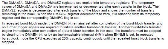
 Introduction The DMA controller transfers data from one address to another, without CPU intervention, across the entire address range.")
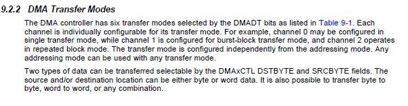
34 DMA Controller The direct memory access (DMA) controller module transfers data from one address to another, without CPU intervention. This chapter describes the operation of the DMA controller. Direct Memory Access (DMA) Introduction The DMA controller transfers data from one address to another, without CPU intervention, across the entire address range. For example, the DMA controller can move data from the ADC conversion memory to RAM. Devices that contain a DMA controller may have up to eight DMA channels available. Therefore, depending on the number of DMA channels available, some features described in this chapter are not applicable to all devices. See the device-specific data sheet for number of channels supported. Using the DMA controller can
35 increase the throughput of peripheral modules. It can also reduce system power consumption by allowing the CPU to remain in a low-power mode, without having to awaken to move data to or from a peripheral. DMA controller features include: Up to eight independent transfer channels Configurable DMA channel priorities Requires only two MCLK clock cycles per transfer Byte or word and mixed byte/word transfer capability Block sizes up to bytes or words Configurable transfer trigger selections Selectable-edge or level-triggered transfer Four addressing modes Single, block, or burst-block transfer modes
36
37
38
39
40

41 CASE STUDY: Remote Controller of Air Conditioner Using MSP430 System Description This board demonstrates an ultra-low power, general purpose, infrared remote controller solution. The board uses a FRAM-based MCU MSP430FR4133, which supports features such as real time clock, button scan, infrared encoding, LED backlight, and LCD display. MSP430FR4133 The MSP430FR4133 is a FRAM-based ultra-low power mixed signal MCU. With the following features, the MSP430FR4133 is highly suitable for portable device applications. 16-bit RISC architecture up to 16 Mhz Wide supply voltage range from 1.8 V to 3.6 V 64-Pin/56-Pin/48Pin TSSOP/LQFP package options
42 Integrated LCD driver with charge pump can support up to 4x36 or 8x32 segment LCD Optimized 16-bit timer for infrared signal generation Low power mode (LPM3.5) with RTC on:0.77 ua Low power mode (LPM3.5) with LCD on: ua Active mode: 126 ua/mhz 10^15 write cycle endurance low power ferroelectric RAM (FRAM) can be used to store data 10-channel, 10-bit analog-to-digital converter (ADC) with built-in 1.5 V reference for battery powered system All I/Os are capacitive touch I/O CIRCUIT: A 4x28 segment LCD is directly connected to the MSP430FR4133 LCD driver pins. Designers can swap the COM and SEG pins to simplify the PCB layout. A 4x4 matrix is used to detect 15 buttons. The matrix columns are connected to interrupt-enabled GPIOs (P1) to wake up the MSP430FR4133 from low power mode. MCU internal pull up/pull down resistors are used as button scan matrix pull up resistors. No external resistor is needed for button detection, and no external circuit is needed for battery voltage detection. The function is also realized by the MCU ADC module without any external component. A KHz watch crystal serves as the MCU FLL and RTC clock source. Two chip capacitors, C4 and C6, are used as the crystal loading capacitor. Designers must choose C4 and C6 values carefully according to crystal specification. Cautious PCB layout design for the crystal is strongly recommended, to secure system clock robustness. Software Description The software implements an interrupt-driven structure. In the main loop, the MCU stays in LPM3.5 mode.interrupts from the button, RTC, and timer wake up the MCU for task processing. Inputs from the button are processed in task KeyProcess (), which handles system status and generates the content for the LCD display and infrared signal. RTC generates a 3S interval interrupt to inform the system of battery voltage measurement.

43
44
45
15.1 Timer_A Introduction
 Chapter 15 is a 16-bit timer/counter with multiple capture/compare registers. This chapter describes. This chapter describes the operation of the of the MSP430x4xx device family. Topic Page 15.1 Introduction.........................................
MSP430 Teaching Materials
 MSP430 Teaching Materials Lecture 5 Timers Description of clock signals Texas Instruments Incorporated University of Beira Interior (PT) Pedro Dinis Gaspar, António Espírito Santo, Bruno Ribeiro, Humberto
CPE 323: MSP430 Timers
 CPE 323: MSP430 Timers Aleksandar Milenkovic Electrical and Computer Engineering The University of Alabama in Huntsville milenka@ece.uah.edu http://www.ece.uah.edu/~milenka Outline Watchdog Timer TimerA
TAxCTL Register
 Timer_A Registers 17.3.1 TAxCTL Register Timer_Ax Control Register Figure 17-16. TAxCTL Register Reserved TASSEL ID MC Reserved TACLR TAIE TAIFG rw-(0) rw-(0) rw-(0) rw-(0) rw-(0) w-(0) rw-(0) rw-(0) 15-10
Timer Module Timer A. ReadMeFirst
 Timer Module Timer A ReadMeFirst Lab Folder Content 1) ReadMeFirst 2) TimerModule Lecture material 3) PinOutSummary 4) InterruptsVectorTable 5) Source code for screencast Interrupt Review Overview A Timer
Timers and Clocks CS4101 嵌入式系統概論. Prof. Chung-Ta King. Department of Computer Science National Tsing Hua University, Taiwan
 CS4101 嵌入式系統概論 Timers and Clocks Prof. Chung-Ta King Department of Computer Science, Taiwan Materials from MSP430 Microcontroller Basics, John H. Davies, Newnes, 2008 Recall the Container Thermometer Container
Hacettepe University
 MSP430 Teaching Materials Week 5 FUNDAMENTALS OF INTERFACING AND TIMERS for MSP430 Hacettepe University Elements in Basic MCU Interface Power Source Feeds CPU and peripherals Clock Oscillators System synchronization
Hello, and welcome to this presentation of the STM32 Real- Time Clock. It covers the main features of this peripheral, which is used to provide a
 Hello, and welcome to this presentation of the STM32 Real- Time Clock. It covers the main features of this peripheral, which is used to provide a very accurate time base. 1 The RTC peripheral features
Hacettepe University
 MSP430 Teaching Materials Week 5 FUNDAMENTALS OF INTERFACING AND TIMERS for MSP430 Hacettepe University Elements in Basic MCU Interface Power Source Feeds CPU and peripherals Clock Oscillators System synchronization
University of Texas at El Paso Electrical and Computer Engineering Department. EE 3176 Laboratory for Microprocessors I.
 University of Texas at El Paso Electrical and Computer Engineering Department EE 3176 Laboratory for Microprocessors I Fall 2016 LAB 03 Low Power Mode and Port Interrupts Goals: Bonus: Pre Lab Questions:
Lab 4 Interrupts ReadMeFirst
 Lab 4 Interrupts ReadMeFirst Lab Folder Content 1) ReadMeFirst 2) Interrupt Vector Table 3) Pin out Summary Objectives Understand how interrupts work Learn to program Interrupt Service Routines in C Language
AVR XMEGA Product Line Introduction AVR XMEGA TM. Product Introduction.
 AVR XMEGA TM Product Introduction 32-bit AVR UC3 AVR Flash Microcontrollers The highest performance AVR in the world 8/16-bit AVR XMEGA Peripheral Performance 8-bit megaavr The world s most successful
CPE 325: Embedded Systems Laboratory Laboratory #7 Tutorial MSP430 Timers, Watchdog Timer, Timers A and B
 CPE 325: Embedded Systems Laboratory Laboratory #7 Tutorial MSP430 Timers, Watchdog Timer, Timers A and B Aleksandar Milenković Email: milenka@uah.edu Web: http://www.ece.uah.edu/~milenka Objective This
MSP430FG4618 Programming Reference Revision 3
 MSP430FG4618/F2013 Experimenter Board MSP430FG4618 Programming Reference Revision 3 George Mason University 1. CPU Registers The CPU incorporates sixteen 20-bit registers. R0, R1, R2 and R3 have dedicated
Lab 4: Interrupt. CS4101 Introduction to Embedded Systems. Prof. Chung-Ta King. Department of Computer Science National Tsing Hua University, Taiwan
 CS4101 Introduction to Embedded Systems Lab 4: Interrupt Prof. Chung-Ta King Department of Computer Science, Taiwan Introduction In this lab, we will learn interrupts of MSP430 Handling interrupts in MSP430
CPE 323 Introduction to Embedded Computer Systems: MSP430 System Architecture An Overview
 CPE 323 Introduction to Embedded Computer Systems: MSP430 System Architecture An Overview Aleksandar Milenkovic Electrical and Computer Engineering The University of Alabama in Huntsville milenka@ece.uah.edu
Lecture 5: MSP430 Interrupt
 ECE342 Intro. to Embedded Systems Lecture 5: MSP430 Interrupt Ying Tang Electrical and Computer Engineering Rowan University 1 How A Computer React to Inputs? Polling: the processor regularly looks at
USB-4303 Specifications
 Specifications Document Revision 1.0, February, 2010 Copyright 2010, Measurement Computing Corporation Typical for 25 C unless otherwise specified. Specifications in italic text are guaranteed by design.
Network Embedded Systems Sensor Networks Fall Hardware. Marcus Chang,
 Network Embedded Systems Sensor Networks Fall 2013 Hardware Marcus Chang, mchang@cs.jhu.edu 1 Embedded Systems Designed to do one or a few dedicated and/or specific functions Embedded as part of a complete
M68HC08 Microcontroller The MC68HC908GP32. General Description. MCU Block Diagram CPU08 1
 M68HC08 Microcontroller The MC68HC908GP32 Babak Kia Adjunct Professor Boston University College of Engineering Email: bkia -at- bu.edu ENG SC757 - Advanced Microprocessor Design General Description The
Chapter 26 Topic Page 26.1 ADC12 Introduction
 Chapter 26 The module is a high-performance 12-bit analog-to-digital converter (ADC). This chapter describes the. The is implemented in the MSP430x43x MSP430x44x, MSP430FG461x devices. Topic Page 26.1
UNIT IV SERIAL COMMUNICATIONS
 UNIT IV SERIAL COMMUNICATIONS Serial channels are the main form of communications used in digital systems nowadays. Diverse forms of serial communication formats and protocols can be found in applications
Design and development of embedded systems for the Internet of Things (IoT) Fabio Angeletti Fabrizio Gattuso
 Fabio Angeletti Fabrizio Gattuso") Design and development of embedded systems for the Internet of Things (IoT) Fabio Angeletti Fabrizio Gattuso Microcontroller It is essentially a small computer on a chip Like any computer, it has memory,
Design and development of embedded systems for the Internet of Things (IoT) Fabio Angeletti Fabrizio Gattuso Microcontroller It is essentially a small computer on a chip Like any computer, it has memory,
What is an Interrupt?
 MSP430 Interrupts What is an Interrupt? Reaction to something in I/O (human, comm link) Usually asynchronous to processor activities interrupt handler or interrupt service routine (ISR) invoked to take
Question Bank Microprocessor and Microcontroller
 QUESTION BANK - 2 PART A 1. What is cycle stealing? (K1-CO3) During any given bus cycle, one of the system components connected to the system bus is given control of the bus. This component is said to
ECSE-426. Microprocessor Systems. 2: Assembly + C 1
 ECSE-426 Microprocessor Systems 2: Assembly + C 1 Today s Lecture Theory Tutorial Appendix Multi-level machines Problem-oriented language layer Language Choice Machine Architecture Introduction to the
ZigBee Compliant Platform 2.4G RF Low Power Transceiver Module for IEEE Standard. DATA SHEET Version B
 ZMD400-A01 ZigBee Compliant Platform 2.4G RF Low Power Transceiver Module for IEEE 802.15.4 Standard DATA SHEET Version B Quan International Co., Ltd., ZMD400 Features Fully compliant 802.15.4 Standard
Embedded Systems. 3. Hardware Software Interface. Lothar Thiele. Computer Engineering and Networks Laboratory
 Embedded Systems 3. Hardware Software Interface Lothar Thiele Computer Engineering and Networks Laboratory Do you Remember? 3 2 3 3 High Level Physical View 3 4 High Level Physical View 3 5 What you will
8-bit Microcontroller. Application Note. AVR134: Real-Time Clock (RTC) using the Asynchronous Timer. Features. Theory of Operation.
 using the Asynchronous Timer. Features. Theory of Operation.") AVR134: Real-Time Clock (RTC) using the Asynchronous Timer Features Real-Time Clock with Very Low Power Consumption (4µA @ 3.3V) Very Low Cost Solution Adjustable Prescaler to Adjust Precision Counts Time,
AVR134: Real-Time Clock (RTC) using the Asynchronous Timer Features Real-Time Clock with Very Low Power Consumption (4µA @ 3.3V) Very Low Cost Solution Adjustable Prescaler to Adjust Precision Counts Time,
 Distributed by: www.jameco.com 1-800-831-4242 The content and copyrights of the attached material are the property of its owner. MSP430F11x2/12x2 Device Erratasheet Current Version Devices MSP430F1122
DS1306. Serial Alarm Real Time Clock (RTC)
") www.dalsemi.com FEATURES Real time clock counts seconds, minutes, hours, date of the month, month, day of the week, and year with leap year compensation valid up to 2100 96-byte nonvolatile RAM for data
www.dalsemi.com FEATURES Real time clock counts seconds, minutes, hours, date of the month, month, day of the week, and year with leap year compensation valid up to 2100 96-byte nonvolatile RAM for data
Chapter 1 MSP430 Microcontroller Family
 Chapter 1 1-1 Introduction 1.1 Introduction The MSP430 is a 16-bit microcontroller that has a number of special features not commonly available with other microcontrollers: Complete system on-a-chip includes
AVR XMEGA TM. A New Reference for 8/16-bit Microcontrollers. Ingar Fredriksen AVR Product Marketing Director
 AVR XMEGA TM A New Reference for 8/16-bit Microcontrollers Ingar Fredriksen AVR Product Marketing Director Kristian Saether AVR Product Marketing Manager Atmel AVR Success Through Innovation First Flash
AVR134: Real Time Clock (RTC) Using the Asynchronous Timer. Features. Introduction. AVR 8-bit Microcontrollers APPLICATION NOTE
 Using the Asynchronous Timer. Features. Introduction. AVR 8-bit Microcontrollers APPLICATION NOTE") AVR 8-bit Microcontrollers AVR134: Real Time Clock (RTC) Using the Asynchronous Timer APPLICATION NOTE Features Real Time Clock with Very Low Power Consumption (10µA @ 3.3V) Very Low Cost Solution Adjustable
AVR 8-bit Microcontrollers AVR134: Real Time Clock (RTC) Using the Asynchronous Timer APPLICATION NOTE Features Real Time Clock with Very Low Power Consumption (10µA @ 3.3V) Very Low Cost Solution Adjustable
SANKALCHAND PATEL COLLEGE OF ENGINEERING, VISNAGAR. ELECTRONICS & COMMUNICATION DEPARTMENT Question Bank- 1
 SANKALCHAND PATEL COLLEGE OF ENGINEERING, VISNAGAR ELECTRONICS & COMMUNICATION DEPARTMENT Question Bank- 1 Subject: Microcontroller and Interfacing (151001) Class: B.E.Sem V (EC-I & II) Q-1 Explain RISC
CPE 323 Introduction to Embedded Computer Systems: ADC12 and DAC12. Instructor: Dr Aleksandar Milenkovic Lecture Notes
 CPE 323 Introduction to Embedded Computer Systems: ADC12 and DAC12 Instructor: Dr Aleksandar Milenkovic Lecture Notes Outline MSP430: System Architecture ADC12 Module DAC12 Module CPE 323 2 ADC12 Introduction
// Conditions for 9600/4=2400 Baud SW UART, SMCLK = 1MHz #define Bitime_5 0x05*4 // ~ 0.5 bit length + small adjustment #define Bitime 13*4//0x0D
 /****************************************************************************** * * * 1. Device starts up in LPM3 + blinking LED to indicate device is alive * + Upon first button press, device transitions
Infineon C167CR microcontroller, 256 kb external. RAM and 256 kb external (Flash) EEPROM. - Small single-board computer (SBC) with an
 EEPROM. - Small single-board computer (SBC) with an") Microcontroller Basics MP2-1 week lecture topics 2 Microcontroller basics - Clock generation, PLL - Address space, addressing modes - Central Processing Unit (CPU) - General Purpose Input/Output (GPIO)
Microcontroller Basics MP2-1 week lecture topics 2 Microcontroller basics - Clock generation, PLL - Address space, addressing modes - Central Processing Unit (CPU) - General Purpose Input/Output (GPIO)
Arduino Uno R3 INTRODUCTION
 Arduino Uno R3 INTRODUCTION Arduino is used for building different types of electronic circuits easily using of both a physical programmable circuit board usually microcontroller and piece of code running
UNIT V MICRO CONTROLLER PROGRAMMING & APPLICATIONS TWO MARKS. 3.Give any two differences between microprocessor and micro controller.
 UNIT V -8051 MICRO CONTROLLER PROGRAMMING & APPLICATIONS TWO MARKS 1. What is micro controller? Micro controller is a microprocessor with limited number of RAM, ROM, I/O ports and timer on a single chip
Introduction to Embedded Systems
 Stefan Kowalewski, 4. November 25 Introduction to Embedded Systems Part 2: Microcontrollers. Basics 2. Structure/elements 3. Digital I/O 4. Interrupts 5. Timers/Counters Introduction to Embedded Systems
Clock and Fuses. Prof. Prabhat Ranjan Dhirubhai Ambani Institute of Information and Communication Technology, Gandhinagar
 Clock and Fuses Prof. Prabhat Ranjan Dhirubhai Ambani Institute of Information and Communication Technology, Gandhinagar Reference WHY YOU NEED A CLOCK SOURCE - COLIN O FLYNN avrfreaks.net http://en.wikibooks.org/wiki/atmel_avr
University of Texas at El Paso Electrical and Computer Engineering Department. EE 3176 Laboratory for Microprocessors I.
 University of Texas at El Paso Electrical and Computer Engineering Department EE 3176 Laboratory for Microprocessors I Fall 2016 LAB 04 Timer Interrupts Goals: Learn about Timer Interrupts. Learn how to
Interconnects, Memory, GPIO
 Interconnects, Memory, GPIO Dr. Francesco Conti f.conti@unibo.it Slide contributions adapted from STMicroelectronics and from Dr. Michele Magno, others Processor vs. MCU Pipeline Harvard architecture Separate
Texas Instruments Mixed Signal Processor Tutorial Abstract
 Texas Instruments Mixed Signal Processor Tutorial Abstract This tutorial goes through the process of writing a program that uses buttons to manipulate LEDs. One LED will be hard connected to the output
Lecture-55 System Interface:
 Lecture-55 System Interface: To interface 8253 with 8085A processor, CS signal is to be generated. Whenever CS =0, chip is selected and depending upon A 1 and A 0 one of the internal registers is selected
SEIKO EPSON CORPORATION
 CMOS 16-bit Application Specific Controller 16-bit RISC CPU Core S1C17 (Max. 33 MHz operation) 128K-Byte Flash ROM 16K-Byte RAM (IVRAM are shared by CPU and LCDC) DSP function (Multiply, Multiply and Accumulation,
Understanding the basic building blocks of a microcontroller device in general. Knows the terminologies like embedded and external memory devices,
 Understanding the basic building blocks of a microcontroller device in general. Knows the terminologies like embedded and external memory devices, CISC and RISC processors etc. Knows the architecture and
SH69P55A EVB. Application Note for SH69P55A EVB SH69P55A EVB SH69V55A
 Application Note for SH69P55A EVB SH69P55A EVB The SH69P55A EVB is used to evaluate the SH69P55A chip's function for the development of application program. It contains of a SH69V55A chip to evaluate the
MSP430 Interrupts. Change value of internal variable (count) Read a data value (sensor, receive) Write a data value (actuator, send)
 Read a data value (sensor, receive) Write a data value (actuator, send)") MSP430 Interrupts What is an Interrupt? Reaction to something in I/O (human, comm link) Usually asynchronous to processor activities interrupt handler or interrupt service routine (ISR) invoked to take
MSP430 Interrupts What is an Interrupt? Reaction to something in I/O (human, comm link) Usually asynchronous to processor activities interrupt handler or interrupt service routine (ISR) invoked to take
MSP430. More on MSP430
 MSP430 More on MSP430 CodeComposer TI recently launched Code Composer Essentials v3. This IDE s latest version (version 3) supports all available MSP430 devices. The new features of CCE v3 include: - Free
Application Report. 1 Hardware Description. John Fahrenbruch... MSP430 Applications
 Application Report SLAA309 June 2006 Low-Power Tilt Sensor Using the MSP430F2012 John Fahrenbruch... MSP430 Applications ABSTRACT The MSP430 family of low-power microcontrollers are ideal for low-power
MICROCONTROLLER AND PLC LAB-436 SEMESTER-5
 MICROCONTROLLER AND PLC LAB-436 SEMESTER-5 Exp:1 STUDY OF MICROCONTROLLER 8051 To study the microcontroller and familiarize the 8051microcontroller kit Theory:- A Microcontroller consists of a powerful
IV B.Tech. I Sem (R13) ECE : Embedded Systems : UNIT -2 1 UNIT 2
 ECE : Embedded Systems : UNIT -2 1 UNIT 2") IV B.Tech. I Sem (R13) ECE : Embedded Systems : UNIT -2 1 UNIT 2 1. Block diagram of MSP430x5xx series micro-controller --------------------- 1 2. CPU architecture of MSP430x5xx ------------------------------------------------
IV B.Tech. I Sem (R13) ECE : Embedded Systems : UNIT -2 1 UNIT 2 1. Block diagram of MSP430x5xx series micro-controller --------------------- 1 2. CPU architecture of MSP430x5xx ------------------------------------------------
2-Oct-13. the world s most energy friendly microcontrollers and radios
 1 2 3 EFM32 4 5 LESENSE Low Energy Sensor Interface Autonomous sensing in Deep Sleep LESENSE with central control logic ACMP for sensor input DAC for reference generation Measure up to 16 sensors Inductive
Topics. Interfacing chips
 8086 Interfacing ICs 2 Topics Interfacing chips Programmable Communication Interface PCI (8251) Programmable Interval Timer (8253) Programmable Peripheral Interfacing - PPI (8255) Programmable DMA controller
64-Kbit (8 K 8) SPI nvsram with Real Time Clock
 SPI nvsram with Real Time Clock") 64-Kbit (8 K 8) SPI nvsram with Real Time Clock 64-Kbit (8 K 8) SPI nvsram with Real Time Clock Features 64-Kbit nonvolatile static random access memory (nvsram) Internally organized as 8 K 8 STORE to
64-Kbit (8 K 8) SPI nvsram with Real Time Clock 64-Kbit (8 K 8) SPI nvsram with Real Time Clock Features 64-Kbit nonvolatile static random access memory (nvsram) Internally organized as 8 K 8 STORE to
Interrupt/Timer/DMA 1
 Interrupt/Timer/DMA 1 Exception An exception is any condition that needs to halt normal execution of the instructions Examples - Reset - HWI - SWI 2 Interrupt Hardware interrupt Software interrupt Trap
ARDUINO MEGA INTRODUCTION
 ARDUINO MEGA INTRODUCTION The Arduino MEGA 2560 is designed for projects that require more I/O llines, more sketch memory and more RAM. With 54 digital I/O pins, 16 analog inputs so it is suitable for
Chapter 2. Overview of Architecture and Microcontroller-Resources
 Chapter 2 Overview of Architecture and Microcontroller-Resources Lesson 4 Timers, Real Time Clock Interrupts and Watchdog Timer 2 Microcontroller-resources Port P1 Port P0 Port P2 PWM Timers Internal Program
EEE3410 Microcontroller Applications Department of Electrical Engineering Lecture 4 The 8051 Architecture
 Department of Electrical Engineering Lecture 4 The 8051 Architecture 1 In this Lecture Overview General physical & operational features Block diagram Pin assignments Logic symbol Hardware description Pin
1-Mbit (128K 8) Serial (SPI) nvsram with Real-Time Clock
 Serial (SPI) nvsram with Real-Time Clock") 1-Mbit (128K 8) Serial (SPI) nvsram with Real-Time Clock 1-Mbit (128K 8) Serial (SPI) nvsram with Real Time Clock Features 1-Mbit nonvolatile static random access memory (nvsram) Internally organized as
1-Mbit (128K 8) Serial (SPI) nvsram with Real-Time Clock 1-Mbit (128K 8) Serial (SPI) nvsram with Real Time Clock Features 1-Mbit nonvolatile static random access memory (nvsram) Internally organized as
EE6008-Microcontroller Based System Design Department Of EEE/ DCE
 UNIT- II INTERRUPTS AND TIMERS PART A 1. What are the interrupts available in PIC? (Jan 14) Interrupt Source Enabled by Completion Status External interrupt from INT INTE = 1 INTF = 1 TMR0 interrupt T0IE
AD3300/ADA3300 User s Manual
 AD3300/ADA3300 User s Manual Real Time Devices USA, Inc. Accessing the Analog World Publication No. 3300-4/22/97 AD3300/ADA3300 User s Manual REAL TIME DEVICES USA, INC. Post Office Box 906 State College,
TouchCore351-ML16IP. Capacitive Touch Sensor Controller
 Total Solution of MCU TouchCore351-ML16IP Capacitive Touch Sensor Controller CORERIVER Semiconductor reserves the right to make corrections, modifications, enhancements, improvements, and other changes
AN 367: Implementing PLL Reconfiguration in Stratix II Devices
 AN 367: Implementing PLL Reconfiguration in Stratix II Devices July 2012 AN-367-2.2 Introduction Phase-locked loops (PLLs) use several divide counters and different voltage-controlled oscillator (VCO)
DP8571A Timer Clock Peripheral (TCP)
") DP8571A Timer Clock Peripheral (TCP) General Description The DP8571A is intended for use in microprocessor based systems where information is required for multi-tasking data logging or general time of
DP8571A Timer Clock Peripheral (TCP) General Description The DP8571A is intended for use in microprocessor based systems where information is required for multi-tasking data logging or general time of
CENG-336 Introduction to Embedded Systems Development. Timers
 CENG-336 Introduction to Embedded Systems Development Timers Definitions A counter counts (possibly asynchronous) input pulses from an external signal A timer counts pulses of a fixed, known frequency
8-bit Microcontroller with 4K Bytes In-System Programmable Flash. ATtiny40. Preliminary
 Features High Performance, Low Power AVR 8-Bit Microcontroller Advanced RISC Architecture 54 Powerful Instructions Most Single Clock Cycle Execution 16 x 8 General Purpose Working Registers Fully Static
MSP430 Teaching Materials
 MSP430 Teaching Materials Lecture 8 Direct Memory Access (DMA) & Communications Introduction Texas Instruments t Incorporated University of Beira Interior (PT) Pedro Dinis Gaspar, António Espírito Santo,
Timers and Counters. LISHA/UFSC Prof. Dr. Antônio Augusto Fröhlich Fauze Valério Polpeta Lucas Francisco Wanner.
 Timers and Counters LISHA/UFSC Prof. Dr. Antônio Augusto Fröhlich Fauze Valério Polpeta Lucas Francisco Wanner http://www.lisha.ufsc.br/~guto March 2009 March 2009 http://www.lisha.ufsc.br/ 103 Timers
063[[[0LFURFRQWUROOHUV /RZ3RZHU0RGHV &3($GYDQFHG0LFURFRPSXWHU7HFKQLTXHV 'U(PLO-RYDQRY /RZ3RZHU. Power: A First-Class Architectural Design Constraint
 063[[[0LFURFRQWUROOHUV /RZ3RZHU0RGHV &3($GYDQFHG0LFURFRPSXWHU7HFKQLTXHV 'U(PLO-RYDQRY MSP430 low power concepts 1 /RZ3RZHU Power: A First-Class Architectural Design Constraint Trevor Mudge, IEEE Computer,
Registers Format. 4.1 I/O Port Address
 4 Registers Format The detailed descriptions of the register format and structure of the ACL- 8112 are specified in this chapter. This information is quite useful for the programmer who wish to handle
Microcontroller & Interfacing
 Course Title Course Code Microcontroller & Interfacing EC406 Lecture : 3 Course Credit Practical : 1 Tutorial : 0 Total : 4 Course Objective At the end of the course the students will be able to Understand
AD3500/ADA3500 User s Manual
 AD3500/ADA3500 User s Manual Real Time Devices USA, Inc. Accessing the Analog World Publication No. 3500-5/1/97 AD3500/ADA3500 User s Manual REAL TIME DEVICES USA, INC. Post Office Box 906 State College,
For reference only Refer to the latest documents for details
 STM32F3 Technical Training For reference only Refer to the latest documents for details STM32F37x Specific Features/ peripherals Sigma delta analog to digital converter (SDADC) SDADC introduction (1/2)
5xx Active & Low Power Mode Operation
 5xx Active & Low Power Mode Operation 38 Lab 2: ULP Operation Lab Goals Learn ULP Best Practices Learn & understand how to configure two key modules of the 5xx to achieve ultra-low power operation. Power
Unlocking the Potential of Your Microcontroller
 Unlocking the Potential of Your Microcontroller Ethan Wu Storming Robots, Branchburg NJ, USA Abstract. Many useful hardware features of advanced microcontrollers are often not utilized to their fullest
Product Technical Brief S3C2440X Series Rev 2.0, Oct. 2003
 Product Technical Brief S3C2440X Series Rev 2.0, Oct. 2003 S3C2440X is a derivative product of Samsung s S3C24XXX family of microprocessors for mobile communication market. The S3C2440X s main enhancement
Product Technical Brief S3C2412 Rev 2.2, Apr. 2006
 Product Technical Brief S3C2412 Rev 2.2, Apr. 2006 Overview SAMSUNG's S3C2412 is a Derivative product of S3C2410A. S3C2412 is designed to provide hand-held devices and general applications with cost-effective,
ECE2049: Embedded Computing in Engineering Design C Term Spring Lecture #11: More Clocks and Timers
 ECE2049: Embedded Computing in Engineering Design C Term Spring 2018 Lecture #11: More Clocks and Timers Reading for Today: Davie's Ch 8.3-8.4, 8.9-8.10, User's Guide Ch. 17 Reading for Next Class: User's
Architecture of Computers and Parallel Systems Part 6: Microcomputers
 Architecture of Computers and Parallel Systems Part 6: Microcomputers Ing. Petr Olivka petr.olivka@vsb.cz Department of Computer Science FEI VSB-TUO Architecture of Computers and Parallel Systems Part
DS1302. Trickle Charge Timekeeping Chip FEATURES PIN ASSIGNMENT PIN DESCRIPTION
 DS132 Trickle Charge Timekeeping Chip FEATURES Real time clock counts seconds, minutes, hours, date of the month, month, day of the week, and year with leap year compensation valid up to 21 31 x 8 RAM
2002 Mixed Signal Products SLAU056B
 User s Guide 22 Mixed Signal Products SLAU56B IMPORTANT NOTICE Texas Instruments Incorporated and its subsidiaries (TI) reserve the right to make corrections, modifications, enhancements, improvements,
PIC Microcontroller Introduction
 PIC Microcontroller Introduction The real name of this microcontroller is PICmicro (Peripheral Interface Controller), but it is better known as PIC. Its first ancestor was designed in 1975 by General Instruments.
Interrupts CS4101 嵌入式系統概論. Prof. Chung-Ta King. Department of Computer Science National Tsing Hua University, Taiwan
 CS4101 嵌入式系統概論 Interrupts Prof. Chung-Ta King Department of Computer Science, Taiwan Materials from MSP430 Microcontroller Basics, John H. Davies, Newnes, 2008 Inside MSP430 (MSP430G2551) 1 Introduction
8254 is a programmable interval timer. Which is widely used in clock driven digital circuits. with out timer there will not be proper synchronization
 8254 is a programmable interval timer. Which is widely used in clock driven digital circuits. with out timer there will not be proper synchronization between two devices. So it is very useful chip. The
DS1306 Serial Alarm Real-Time Clock
 Serial Alarm Real-Time Clock www.maxim-ic.com FEATURES Real-Time Clock (RTC) Counts Seconds, Minutes, Hours, Date of the Month, Month, Day of the Week, and Year with Leap-Year Compensation Valid Up to
CN310 Microprocessor Systems Design
 CN310 Microprocessor Systems Design Microcontroller Nawin Somyat Department of Electrical and Computer Engineering Thammasat University Outline Course Contents 1 Introduction 2 Simple Computer 3 Microprocessor
Freescale s Next Generation 8-bit LCD Solutions
 Freescale s Next Generation 8-bit LCD Solutions When most consumers think of LCD, they probably envision a flat panel television or computer monitor. However, there are millions more LCDs out there that
If It s Electronic, It Needs a Clock
 REAL-TIME CLOCKS MIXED-SIGNAL DESIGN GUIDE Data Sheets Application Notes Free Samples If It s Electronic, It Needs a Clock 8th EDITION No matter what you design, you need your system to accurately keep
UNIT - II PERIPHERAL INTERFACING WITH 8085
 UNIT - II PERIPHERAL INTERFACING WITH 8085 Peripheral Interfacing is considered to be a main part of Microprocessor, as it is the only way to interact with the external world. The interfacing happens with
2.996/6.971 Biomedical Devices Design Laboratory Lecture 6: Microprocessors II
 2.996/6.971 Biomedical Devices Design Laboratory Lecture 6: Microprocessors II Instructor: Dr. Hong Ma Oct. 1, 2007 Structure of MSP430 Program 1. Declarations 2. main() 1. Watch-dog timer servicing 2.
TEVATRON TECHNOLOGIES PVT. LTD Embedded! Robotics! IoT! VLSI Design! Projects! Technical Consultancy! Education! STEM! Software!
 Summer Training 2016 Advance Embedded Systems Fast track of AVR and detailed working on STM32 ARM Processor with RTOS- Real Time Operating Systems Covering 1. Hands on Topics and Sessions Covered in Summer
Hello, and welcome to this presentation of the STM32 Touch Sensing Controller (TSC) which enables the designer to simply add touch sensing
 which enables the designer to simply add touch sensing") Hello, and welcome to this presentation of the STM32 Touch Sensing Controller (TSC) which enables the designer to simply add touch sensing functionality to any application. 1 Over recent years, Touch Sensing
Hello, and welcome to this presentation of the STM32 Touch Sensing Controller (TSC) which enables the designer to simply add touch sensing functionality to any application. 1 Over recent years, Touch Sensing
1. INTRODUCTION TO MICROPROCESSOR AND MICROCOMPUTER ARCHITECTURE:
 1. INTRODUCTION TO MICROPROCESSOR AND MICROCOMPUTER ARCHITECTURE: A microprocessor is a programmable electronics chip that has computing and decision making capabilities similar to central processing unit
3. The MC6802 MICROPROCESSOR
 3. The MC6802 MICROPROCESSOR This chapter provides hardware detail on the Motorola MC6802 microprocessor to enable the reader to use of this microprocessor. It is important to learn the operation and interfacing
ECE PRACTICE EXAM #2 Clocks, Timers, and Digital I/O
 ECE2049 -- PRACTICE EXAM #2 Clocks, Timers, and Digital I/O Study HW3, Class Notes, Davies Ch 2.6, 5.8, 8, 9.2-3, 9.7, MSP43F5529 User's Guide Ch 5, 17, 28 Work all problems with your note sheet first
STM32G0 MCU Series Efficiency at its Best
 STM32G0 MCU Series Efficiency at its Best Key Messages of STM32G0 Series 2 2 3 Efficient Arm Cortex -M0+ at 64 MHz Compact cost: maximum I/Os count Best RAM/Flash Ratio Smallest possible package down to
Product Technical Brief S3C2413 Rev 2.2, Apr. 2006
 Product Technical Brief Rev 2.2, Apr. 2006 Overview SAMSUNG's is a Derivative product of S3C2410A. is designed to provide hand-held devices and general applications with cost-effective, low-power, and