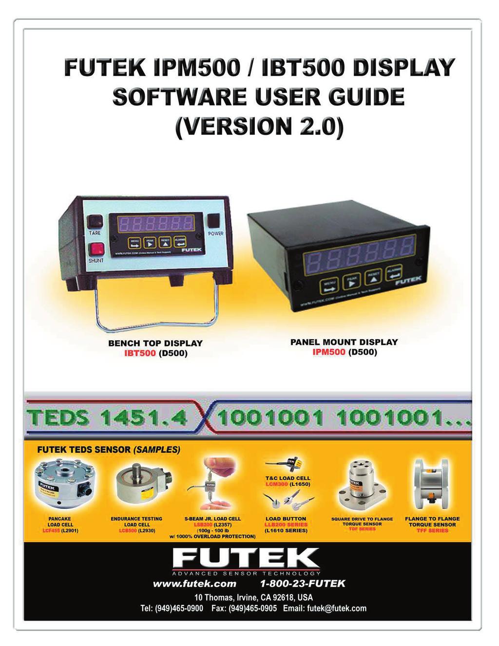
Futek Advanced Sensor Technology- Futek IPM500/IBT500 Software Documentation Rev April 27, 2006
|
|
|
- Alannah Cross
- 6 years ago
- Views:
Transcription
1
- This function allows a valley (low) reading to be displayed on the screen.")
2 DISPLAY TAB FUNCTIONS Tracking Mode (Blue)- Continuous readings from the display are shown on the screen. Peak Mode (Yellow)- This function allows a peak (high) reading to be displayed on the screen. The peak reading will only change if a reading greater then the current reading is registered. Valley Mode (Yellow)- This function allows a valley (low) reading to be displayed on the screen. The valley reading will only change if a reading smaller then the current reading is registered. This feature is useful when monitoring clockwise and counter clockwise torque values or tension and compression load values. Note: Valley Mode and Valley Reset buttons will become active if the display has the peak and valley option. Otherwise only peak will be enabled. TEDS (IEEE1451.4) Indicator- (Available when TEDS option card is installed) When the TEDS icon is dark blue this means there is not a TEDS compliant sensor connected to the display and may require manual entry of the data to set up the display and sensor. When the icon is light blue then a TEDS sensor is connected. If all data parameters are entered in the TEDS chip correctly it will automatically upload the sensor data to the display. This eliminates manual entry mistakes. Tare- Allows you to zero or null out any existing preloads or zero readings in the display. Gross- Shows the actual value of the display including the true zero reading. Peak Reset- Allows the Max Peak value to be reset back to zero so further peak values can be observed. Valley Reset- Allows the Max Valley value shown to be reset back to zero so further valley values can be observed. Sensor ID- If the sensor is not equipped with the TEDS Chip feature, the data parameters can be saved per sensor identification number. This data is entered in using the Sensor tab. To recall the sensor data enter the Sensor ID number and press search. This will locate already saved parameters and load them into the display.

3 SENSOR TAB FUNCTIONS This tab allows the user to enter in different Sensor configurations per Sensor ID. To retrieve and load the data refer to Display Tab Functions- Sensor ID (pg. 2). To begin configuration of a new system enter in the following required information: Sensor ID- Allows entry of Alphanumeric. Sensor Output Type- Select the appropriate type from the drop down list. Decimal Position- When selecting the decimal point value the max resolution of the display must be taken into account. Normal default resolution of the display is but should be verified by checking the jumper selection- Refer to IPM500 manual, Section xyz. Units- Select the appropriate units from the drop down list. Calibration Type 2 pt Calibration- This method requires that the Rated Output and the Maximum Capacity of the sensor be known. The user enters in the low input signal for Lo In (typically at zero load) and the corresponding minimum display reading for Lo Rd. Similarly, the high input signal (Rated Output in mv) is entered for Hi In and the corresponding maximum display reading (Maximum Capacity) for Hi Rd. The meter automatically calculates the scale factor (This requires the second number from the right in the SEtuP menu to be set to 00015). Scale Factor (mx+b)- This method requires that the Offset Value and Scale Factor be known. The sensor does not have to be connected to the meter in order to configure the meter. With this method the user will enter the Offset Value and Scale Factor and the meter will apply the scaling factors to the input signals in order to determine the corresponding displayed values (This requires the second number from the right in the SEtuP menu to be set to 00005). Press the Save button to save the new configuration. (If display was supplied with system calibration then input the data from the calibration certificate)
. Close Port- Allows changes to Com Port and baud rate settings.")

4 RS232 SETUP FUNCTIONS If parameters are not selectable then you must first select the Close Port Button. Com Port- Select the Com Port that the display is connected to. Baud Rate- Set the baud rate equal to the baud rate in the display (FUTEK display default is set to 9600). Close Port- Allows changes to Com Port and baud rate settings. Save Settings- Saves current Com Port and baud rate settings. When using the USB option you must first determine the correct Com Port that the computer assigned the USB drive. This can be done by going to Control Panel and finding the Computer Management -Device Manager. Under Ports find the device CP2101 USB to UART Bridge Controller. In this case it is set for Com Port 9.
 data logging file. Start Test- Begins test based on defined Test Setup parameters.")
. Filter- Select filtered or unfiltered data.")
.")
5 DATA LOG/ANALOG OUTPUT FUNCTIONS Data Logging Test Setup- Define the test interval and test duration (minimum interval is 0.1 sec). Test Interval- This is how often a reading is taken. Test Duration- How long the entire test will last. Create File Path- Set the location of the comma delimited (.csv) data logging file. Start Test- Begins test based on defined Test Setup parameters. The test duration window counts up to the test duration time defined. Stop Test- Stops the test and data logging. Analog Output Setting- Select Current or Voltage Mode (Make sure wiring connection on back of display is correct for current or voltage). Filter- Select filtered or unfiltered data. Decimal Position- Select the correct number of decimal places that will be shown in the Analog Low and High settings in the display. Analog Low- Input the lowest capacity that you want to equal 0V or 4mA (Normally this is set at 0, but can be used to offset the analog signal to allow for a sensor to be used in both directions). Analog High- Input maximum capacity or high point value that you want to equal to 10V or 20mA. Send to Display- This will send and store the above data values in the display. To change them simply input new values and select the Send to Display button.
.")
6 PEAK UTILITY FUNCTIONS The Peak Utility was designed to help customers test numerous parts in a semi/fully automated system and transfer the peak data to a file for SPC analysis. Expected Average Peak- Enter in the expected average peak value (To determine this value several peak tests should be completed before entry of the average peak value). Threshhold %- Set a threshold value as a percentage of Expected Average Peak. Cycle Time- This is to allow enough time to capture the peak value. File Path- Detemines the location to save the peak value readings. Threshhold Value- This value is the calculation of Expected Average Peak multiplied by the Threshhold %. Timer- Shows remaining time left to take the data reading. Readings- Shows maximum peak reading after timer has gone down to zero. Start / Stop Cycle- Starts and Stops the Peak Utility. PEAK UTILITY EXAMPLE Make sure the display is tared or zeroed out before starting the Peak Utility. After pressing the Start Cycle button the display is set in peak mode and a peak reset is initiated. It will continuously monitor the peak readings until the peak value reaches to greater or equal to the Threshold Value. The program would then initiate a countdown timer (The timer is set by the cycle time value). This would allow enough time for the test cycle to be completed and the max peak value to be determined (The user would have to determine the ideal time of their testing cycle). When the timer finishes, the reading is shown in the readings box and stored in the selected file location. After each test the display is set back into tracking mode and then the peak mode and peak reset is reinitialized. If the value being displayed is less than the Threshold Value then the program sits idle until the reading again becomes greater or equal to Threshold Value. Pressing the Stop Cycle button will turn off the peak utility function.

, Template 30 (Voltage Sensors) and Template 31 (Current Loop Sensors). Templates 30 and 31 will only function when using the IPM490.")
7 TEDS FUNCTIONS TEDS (IEEE1451.4)- was designed to eliminate operator entry error and allows the Transducer Electronic Data Sheet to be stored in the sensor for easy retrival. The IPM490/IPM500 and IBT500 are available with the TEDS reader/writer function. This allows the display to be automatically configured when a TEDS sensor is connected. The software allows users to read and write the appropriate parameters to the TEDS Chip. Currently this software only supports the Maxim DS2433 Chip set. The software does support Template 33 (Bridge Sensors), Template 30 (Voltage Sensors) and Template 31 (Current Loop Sensors). Templates 30 and 31 will only function when using the IPM490. Initialize TEDS- This activates the TEDS board (if installed) and deactivates the normal operation mode of the display. The numbers will change and show TEDS. Get TEDS- Retrieves the data parameters from the TEDS Chip and shows the data in the appropriate templates. Template details explained on proceeding pages. Release TEDS- Sends the display back into the normal operational mode. Caution must be taken when writing over existing TEDS data as it is not recoverable. Data Parameters- After selecting the Get TEDS button the data parameters will appear. If the TEDS Chip has been already programmed then the data will show up in the appropriate fields. New- This allows a new file or template to be selected and entry of the data into the correct field. The correct template should be choosen for the appropriate sensor. All fields must be completely filled out. Update- Saves the selected template and all data onto the TEDS Chip. The display is also refreshed with the new data values. Close- Closes the data parameters window of the display and returns to the main TEDS tab.
8 TEDS TEMPLATES DEFINED Basic Template Basic TEDS information used to uniquely identify the sensor and manufacturer. Model Number feature- To create your own custom manufacturer ID and list of model numbers, first locate the directory in which the IPM500/IBT500 software is installed (Default directory is C:\Program Files\Futek\IPM500) and open the file called manu.txt. Manufacturers are listed on each line of the text file in the format of Manufactuer Name, Manufacturer ID Number. Add your own custom information to a new line at the end of the text file using the same format with a unique ID number. Save the file and now create a new text file in the same directory. The name of this new text file should be the same unique ID number assigned earlier. Open the file and type MODEL as the first line of the text file. List model numbers on each subsequent line below this using an alphanumeric format and save the file. This list of model numbers will now appear as a pull down menu in the Model Number section of the basic TEDS template if the unique Manufacturer ID is entered in the appropriate field. Description Manufacturer ID Model Number Version Letter Version Number Serial Number Explanation Defined by companies that have registered with IEEE and have been assigned unique numbers starting with #17. FUTEK has been assigned #55 A sequential numbering system starting from 0 to and is defined by each manufacturer (See Model Number pull down feature above for more information) Revision letter of the product Revision number of the product Unique identification of the sensor. FUTEK refers to this as ID number FUTEK IPM490/IPM500 and IBT500 Custom Settings Located on the bottom of templates #30, #31, and #33, these settings allow the automatic configuration of a FUTEK display once a TEDS enabled sensor is plugged into the system. Description Unit Explanation Decimal Points Number of digits to display to the right of the decimal point. Acceptable values are 0 to 3 User Text Any custom notes for the user Analog Setup Select type of analog output signal Analog Lo V or ma Input signal value that corresponds to the low analog output (Units are in V if voltage is selected for Analog Setup or ma if current is selected) Analog Hi V or ma Input signal value that corresponds to the high analog output (Units are in V if voltage is selected for Analog Setup or ma if current is selected)
9 High Level Voltage Output Sensor Template #30 This template should be used for any sensors with analog voltage output. Description Unit Explanation Transducer Type High Level Voltage Output Template #30 Minimum Physical Value Minimum capacity of the sensor Maximum Physical Value Maximum capacity of the sensor Electrical Value Precision Select the accuracy that best fits the sensor output range Min. Electrical Value V or mv These values are the sensitivity of the sensor and are Max. Electrical Value V or mv determined through calibration or from the FUTEK calibration certificate (Units are in mv if 20mV precision is selected for Electrical Value Precision, otherwise units will be in V) Mapping Method Linear is required Coupling Select whether sensor is AC or DC based Output Impedance Ohm Output resistance of the sensor Response Time sec Not relevant for FUTEK sensors. Setting of is entered. (All fields are required to be completed) Power Requirements Select if sensor requires a power supply Excitation Nominal V This is the normal voltage used when calibrating the FUTEK sensor Excitation Minimum V Lowest voltage that can be used Excitation Maximum V Highest voltage to be used without damage to the sensor Excitation Voltage Type Type of voltage used to calibrate the FUTEK sensor Excitation Current Draw A Maximum current draw at nominal excitation Calibration Date Date and time the calibration of the sensor was performed Calibration Initials Technician that performed the calibration Calibration Period Days Days before the next recalibration is required Measurement Location ID Identification number for physical location of the sensor
10 Current Loop Output Sensor Template #31 This template should be used for any sensors with current loop output (typically 0-20mA or 4-20mA). Description Unit Explanation Transducer Type Current Loop Output Template #31 Minimum Physical Value Minimum capacity of the sensor Maximum Physical Value Maximum capacity of the sensor Electrical Value Precision Select the accuracy that best fits the sensor output range Min. Electrical Value ma These values are the sensitivity of the sensor and are Max. Electrical Value ma determined through calibration or from the FUTEK calibration certificate Mapping Method Linear is required Response Time sec Not relevant for FUTEK sensors. Setting of is entered. (All fields are required to be completed) Power Requirements Select external or internal loop power supply Loop Supply Min V Minimum supply voltage required for a 2-wire system Loop Supply Max V Maximum supply voltage allowed for a 2-wire system Excitation Nominal V This is the normal voltage used when calibrating the FUTEK sensor Excitation Minimum V Lowest voltage that can be used Excitation Maximum V Highest voltage to be used without damage to the sensor Excitation Voltage Type Type of voltage used to calibrate the FUTEK sensor Excitation Current Draw A Maximum current draw at nominal excitation Calibration Date Date and time the calibration of the sensor was performed Calibration Initials Technician that performed the calibration Calibration Period Days Days before the next recalibration is required Measurement Location ID Identification number for physical location of the sensor
11 Bridge Sensor Template #33 This template should be used for any sensors that have a resistive bridge electrical configuration with linear output. Description Unit Explanation Transducer Type Bridge Template #33 Minimum Physical Value Minimum capacity of the sensor Maximum Physical Value Maximum capacity of the sensor Electrical Value Precision 32 Bit Full Precision is preferred for the most accuracy Min. Electrical Value V/V These values are the sensitivity of the sensor and are Max. Electrical Value V/V determined through calibration or from the FUTEK calibration certificate Mapping Method Linear is required Bridge Type Determines what type of bridge is being used. Selection of Quarter, Half and Full bridge are available. FUTEK sensors are normally Full bridge Sensor Impedance Ohm Output resistance of the sensor Response Time sec Not relevant for FUTEK sensors. Setting of is entered. (All fields are required to be completed) Excitation Nominal V This is the normal voltage used when calibrating the FUTEK sensor Excitation Minimum V Lowest voltage that can be used Excitation Maximum V Highest voltage to be used without damage to the sensor Calibration Date Date and time the calibration of the sensor was performed Calibration Initials Technician that performed the calibration Calibration Period Days Days before the next recalibration is required Measurement Location ID Identification number for physical location of the sensor
IPM650 Intelligent Panel-Mount Display
 Quick Start Guide IPM650 Intelligent Panel-Mount Display Sensor Solutions Source Load Torque Pressure Multi Component Calibration Instruments Software www.futek.com Getting Help TECHNICAL SUPPORT For more
IPM500 Series QuickStart Manual
 IPM500 Series QuickStart Manual The Force of Innovation 10 Thomas Irvine, CA 92618 USA (949) 465-0900 FAX: (949) 465-0905 E-Mail: HTUfutek@futek.comUTH www.futek.com Manufacturer of Load Cells, Pressure
SensIT Test and Measurement Version Software Manual
 SensIT Test and Measurement Version 2.1.4000.0 Software Manual 10 Thomas, Irvine, CA 92618, USA Toll Free: (800) 23-FUTEK Telephone: (949) 465-0900 Fax: (949) 465-0905 futek@futek.com www.futek.com 2 Table
FUTEK USB Software Version User s Manual
 FUTEK USB Software Version 2.0.0.0 User s Manual 10 Thomas, Irvine, CA 92618, USA Toll Free: (800) 23-FUTEK Telephone: (949) 465-0900 Fax: (949) 465-0905 futek@futek.com www.futek.com 2 Table of Contents
LAUREL. Laureate Digital Panel Meter for Process and Ratiometric Signals ELECTRONICS, INC. Features. Description
 LAUREL ELECTRONICS, INC. Laureate Digital Panel Meter for Process and Ratiometric Signals Features Reads process signals from ±200 mv to ±600V or ±2 ma to ±5A full scale Ratiometric mode for bridges and
LAUREL. Laureate Digital Panel Meter for Load Cell & Microvolt Input ELECTRONICS, INC. Features. Description
 Description LAUREL ELECTRONICS, INC. Features Laureate Digital Panel Meter for Load Cell & Microvolt Input 20, 50, 100, 250 & 500 mv ranges Span adjust from 0 to ±99,999, zero adjust from -99,999 to +99,999
PIECAL 322 Automated Thermocouple Calibrator Operating Instructions. Product Description. Practical Instrument Electronics
 PIECAL 322 Automated Thermocouple Calibrator Operating Instructions Product Description Easy to use With the PIECAL 322-1 you can check & calibrate all your thermocouple instruments and measure thermocouple
Safety. 2. Configuration - Operation 2.1 RTD Selection 2.2 Driver Test Header. 3. Diagnostics 3.1 ph Input 3.2 Temperature Input
 Safety 1. Installation 1.1 PT:Services 1.2 erature Compensation of 1.3 Controller Services 1.4 Driver Card Installation 1.5 Sensor Part Numbers 1.6 Sensor Wiring 2. Configuration - Operation 2.1 Selection
WARNING: Do not use the thermometer/data logger before you read the users manual and the following instructions.
 55 This unit passes the following tests EN 61326-1:2006 (CISPR11,IEC/EN 61000-3-2:2006, IEC/EN 61000-3-3: 1995+A1 :2001+A2:2005 IEC/EN 61000-4-2/-3/-5/-6/-11) WARNING: Do not use the thermometer/data logger
SY061 Portable Load Meter with IEEE TEDS capability User Instructions
 SY061 Portable Load Meter with IEEE1451.4 TEDS capability User Instructions Preliminary, relates to firmware version 1.2i Introduction The SY061 is a portable load meter, which can indicate the load present
1. Installation. 2. Configuration - Operation. 3. Specifications. Safety
 Safety 1. Installation 1.1 OP_ext: Services 1.2 Driver Card Installation 1.3 Sensor Types 1.4 Sensor Wiring 1.5 Controller Wiring 2. Configuration - Operation 2.1 Replaces ph Sensor 2.2 AS -Flex Series
DPM-3. Transducer Techniques DIGITAL PANEL MOUNT METER PLUG AND PLAY IEEE COMPLIANT OPERATOR MANUAL
 DPM-3 DIGITAL PANEL MOUNT METER PLUG AND PLAY IEEE 1451.4 COMPLIANT OPERATOR MANUAL 4006497 Transducer Techniques R TABLE OF CONTENTS 1. TEDS IEEE 1451.4 INTRODUCTION... 3 2. GENERAL INTRODUCTION... 3
GSV-1A4 M12/2 M12/2. Highlights
 GSV-1A4 M12/2 M12/2 Highlights Input sensitivity: 2mV/V; 4mV/V, 2 mv/v, 1mV/V, 0.5mV/V configurable via jumpers Output signals ±10V AND 12mA+-8mA on 15 pin Sub-D Integrated half and quarter bridge completion
Strain gauge Measuring Amplifier GSV-1A8. Instruction manual GSV-1A8, GSV-1A8USB, GSV-1A16USB
 Strain gauge Measuring Amplifier GSV-1A8 Instruction manual GSV-1A8, GSV-1A8USB, GSV-1A16USB GSV-1A8USB SubD1 (front side) GSV-1A8USB M12 (front side) GSV-1A16USB (rear side) GSV-1A8USB K6D (front side)
10 Thomas, Irvine, CA USA Tel: (949) Fax: (949) IPM650 Product Manual
 Fax: (949) IPM650 Product Manual") IPM650 Product Manual Table of Contents 1 Receiving & Unpacking...- 5-1.1 Unpacking...- 5-1.2 Storage...- 5-1.3 Accessories Supplied...- 5-2 Safety Considerations & Care for Your Device...- 5-3 Important
IPM650 Product Manual Table of Contents 1 Receiving & Unpacking...- 5-1.1 Unpacking...- 5-1.2 Storage...- 5-1.3 Accessories Supplied...- 5-2 Safety Considerations & Care for Your Device...- 5-3 Important
RST INSTRUMENTS LTD.
 RST INSTRUMENTS LTD. VW0420 Analog VW Interface Instruction Manual Ltd. 11545 Kingston St Maple Ridge, BC Canada V2X 0Z5 Tel: (604) 540-1100 Fax: (604) 540-1005 Email: Info@rstinstruments.com i VW0420
USER INSTRUCTION MANUAL FOR LOADCELL TRANSMITTER MODEL TDC/I/0550 (SOFTWARE: VER2A) INDEX
 INDEX") USER INSTRUCTION MANUAL FOR LOADCELL TRANSMITTER MODEL TDC/I/0550 (SOFTWARE: VER2A) INDEX DOCUMENT NO: TDC 0550 MANUAL - 2 1.0) INTRODUCTION. PAGE 2 1.1) ABOUT THIS MANUAL. PAGE 2 1.2) INTRODUCTION. PAGE
USER INSTRUCTION MANUAL FOR LOADCELL TRANSMITTER MODEL TDC/I/0550 (SOFTWARE: VER2A) INDEX DOCUMENT NO: TDC 0550 MANUAL - 2 1.0) INTRODUCTION. PAGE 2 1.1) ABOUT THIS MANUAL. PAGE 2 1.2) INTRODUCTION. PAGE
last update December 1, 2010 reference smtirin06n page 1/21 SMARTEC INFRARED INTERFACE BOARD SMTIRIN06
 1/21 SMARTEC INFRARED INTERFACE BOARD SMTIRIN06 1. Introduction 2. Quick start and functional check Table of contents 3. Hardware inside the SMTIRIN06 system 3.1. General 3.2. Input stage 3.3. Calculation
TR150 Digital Readout Unit SL755. Impact Test Equipment Ltd & User Guide. User Guide
 TR150 Digital Readout Unit SL755 Impact Test Equipment Ltd www.impact-test.co.uk & www.impact-test.com User Guide User Guide Impact Test Equipment Ltd. Building 21 Stevenston Ind. Est. Stevenston Ayrshire
SY021 Portable Load/Force Meter User instructions
 SY021 Portable Load/Force Meter User instructions Relates to firmware version 5.2 INTRODUCTION The SY021 is a portable load meter, which can indicate the load present on any attached cell. A dual channel
IPM490 & IPM500 DIGITAL PANEL METER OWNERS MANUAL
 IPM90 & IPM00 DIGITAL PANEL METER OWNERS MANUAL 0 Thomas, Irvine, CA 98, USA Tel: (99) -0900 Fax: (99) -090 Website: www.futek.com . TABLE OF CONTENTS. TABLE OF CONTENTS.... TEDS INTRODUCTION.... IPM90
MobilControl MC 4000 OWNER S MANUAL
 MobilControl MC 4000 Hand Held Service instrument with data logger for pressure, min / max & differential pressure, temperature, flow / rpm and hydraulic horsepower OWNER S MANUAL 20 7 TERMINALS 7.1 Plugs
LCM SYSTEMS. TR150 Portable Battery Powered Indicator. Instruction Manual. Software version V2.XX
 TR50 Portable Battery Powered Indicator Instruction Manual Software version V2.XX CONTENTS What is TEDS? Basic concept How it works Advantages Introduction User operation Electrical connection information
M3S Series Super-space-saving Signal Conditioners. PC CONFIGURATOR SOFTWARE Model: M3SCFG. Users Manual
 M3S Series Super-space-saving Signal Conditioners PC CONFIGURATOR SOFTWARE Model: M3SCFG Users Manual 5-2-55, Minamitsumori, Nishinari-ku, Osaka 557-0063 JAPAN Tel: +81-6-6659-8201 Fax: +81-6-6659-8510
EDX-10 Series. Compact Recording System
 3-51 EDX-10 Series Compact Recording System Compact & lightweight, with a simple configuration, all channels synchronous 20 khz high-speed sampling (For 4 channels) Control Unit EDX-10B A unit controls
MODEL 9250 Preliminary data sheet
 Delivery: ex stock Warranty: 24 months Universal Instrumentation Amplifier for strain gage, potentiometric, DC/DC and incremental sensors MODEL 9250 Preliminary data sheet NEW burster TEDS Highlights Ultra-fast
SCALE LINK - SL2 Technical Manual
 SCALE LINK - SL2 Technical Manual Fort Atkinson, Wisconsin USA www.digi-star.com www.topconpositioning.com/agriculture D4204-EN Rev A October 31, 2017 TABLE OF CONTENTS Reference Documents... 3 Applicable
TRACKER 240 SERIES. Load Cell and Weighing Indicators. A Precision Measurement Instrument with Outstanding Features
 TRACKER 240 SERIES Load Cell and Weighing Indicators A Precision Measurement Instrument with Outstanding Features TRACKER 240 SERIES INDICATORS Ratiometric Measurement Tare and Auto Transducer Excitation
LAUREL. Laureate Rate Meter & Totalizer with Functions A+B, A-B, AxB, A/B, A/B-1 ELECTRONICS, INC. Features. Description
 Description LAUREL ELECTRONICS, INC. Features Laureate Rate Meter & Totalizer with Functions A+B, A-B, AxB, A/B, A/B-1 Arithmetic functions A+B, A-B, AxB, A/B, A/B-1 applied to rate or total for channels
D115 The Fast Optimal Servo Amplifier For Brush, Brushless, Voice Coil Servo Motors
 D115 The Fast Optimal Servo Amplifier For Brush, Brushless, Voice Coil Servo Motors Ron Boe 5/15/2014 This user guide details the servo drives capabilities and physical interfaces. Users will be able to
Strain gauge Measuring Amplifier GSV-1A8. Instruction manual GSV-1A8, GSV-1A8USB, GSV-1A16USB
 Strain gauge Measuring Amplifier GSV-A8 Instruction manual GSV-A8, GSV-A8USB, GSV-A6USB GSV-A8USB SubD5 (front side) GSV-A8USB M2 (front side) GSV-A6USB (rear side) GSV-A8USB K6D (front side) Version:
Transducers for Pt-100/1000, Resistors
 Transducers for Pt-100/1000, Resistors Microprocessor-based technology General Description Isolating transducers with digital programming of ranges, for DIN-rails or for printed circuit boards. Modules
Jandel RM3 operating instructions
 Jandel RM3 operating instructions Features Integrated Custom Membrane and Keypad LCD Display 16 x 2 Numeric Keypad for entry of selected current User programmable set currents selected by pressing one
RN-174 WiFly Super Module
 RN- WiFly Super Module Features Evaluation board for the RN- module Supports chip antenna (RN--C), PCB trace antenna (RN--P), wire antenna (RN--W), and U.FL connector for an external antenna (RN--U) Ultra-low
LAUREL. Laureate RTD Temperature Panel Meter / Controller ELECTRONICS, INC. Features. Description. Specifications
 LAUREL ELECTRONICS, INC. Laureate RTD Temperature Panel Meter / Controller Features Factory calibrated for 100Ω platinum, 10Ω copper & 120Ω nickel RTDs 2, 3 or 4-wire connection with lead resistance compensation
EDX-10 Series. Compact Recording System
 3-49 EDX-10 Series Compact Recording System Compact, lightweight, with a simple configuration, all channels synchronous 20 khz high-speed sampling (For 4 channels) Control Unit EDX-10B A unit controls
8051 Intermidiate Development Board. Product Manual. Contents. 1) Overview 2) Features 3) Using the board 4) Troubleshooting and getting help
 Overview 2) Features 3) Using the board 4) Troubleshooting and getting help") 8051 Intermidiate Development Board Product Manual Contents 1) Overview 2) Features 3) Using the board 4) Troubleshooting and getting help 1. Overview 2. Features The board is built on a high quality FR-4(1.6
8051 Intermidiate Development Board Product Manual Contents 1) Overview 2) Features 3) Using the board 4) Troubleshooting and getting help 1. Overview 2. Features The board is built on a high quality FR-4(1.6
MODEL 8000MP LEVEL SENSOR
 1 MODEL 8000MP LEVEL SENSOR INSTRUCTIONS FOR INSTALLATION, OPERATION & MAINTENANCE VISIT OUR WEBSITE SIGMACONTROLS.COM 2 SERIES 8000MP LEVEL SENSOR 1. DESCRIPTION The Model 8000MP Submersible Level Sensor
PSD Strain Gauge or Load Cell Hand Held Display TEDS enabled
 TEDS Enabled TEDS enabled 2 label options available for the PSD PSD Strain Gauge or Load Cell Hand Held Display TEDS enabled User Manual www.mantracourt.co.uk What is TEDS?...2 Basic concept...2 How it
WinCT-DLC Windows data communication software Instruction manual
 WinCT-DLC Windows data communication software Instruction manual 1WMPD4003389A 1. Introduction This software, WinCT-DLC, is Windows data communication software that transfers measured data from a USB load
The PM1000 series is a universal 4 digit LED plug-on display for transmitters with 4-20mA 2 wire output and fitted with DIN43650 connector.
 PM1000 SERIES PLUG-ON DISPLAY BRIGHT LED DISPLAY INDICATION RANGE -999 TO +9999 FITS TO DIN 43650 CONNECTOR PLUG-ON TO ANY TRANSMITTER WITH 4-20MA OUTPUT EASY TO SCALE ON SITE ROBUST DESIGN SET POINT OPTION
Model R5005. Instruction Manual. True RMS Industrial Multimeter. reedinstruments. www. com
 Model R5005 True RMS Industrial Multimeter Instruction Manual reedinstruments com Table of Contents Safety... 4 Features... 5 Specifications...5-6 Instrument Description...7-8 Operating Instructions...9-13
PIECAL 520B & 521B Thermocouple Source Operating Instructions
 PIECAL 520B & 521B Thermocouple Source Operating Instructions (Shown without optional boot) Product Description (Shown with optional boot) Easy to use With the PIECAL 520B/521B you can check & calibrate
TouchKit TouchScreen Controller User Manual for Windows NT4 Version: 3.4.0
 TouchKit TouchScreen Controller User Manual for Windows NT4 Version: 3.4.0 1 CONTENT CHAPTER 1. TOUCH PANEL CONTROLLER 2 1.1 Controller 2 1.2 Specifications and Features 3 CHAPTER 2. INSTALLING TOUCHKIT
TouchKit Touch Panel User manual for Windows9X/ME Version: 3.1.4
 TouchKit Touch Panel User manual for Windows9X/ME Version: 3.1.4 TouchKit Touch Panel v3.1.4 0 CONTENT CHAPTER 1. TOUCH PANEL CONTROLLER... 2 1.1 CONTROLLER... 2 1.2 SPECIFICATIONS AND FEATURES... 3 CHAPTER
7561-PSD Manual Portable Battery Powered Indicator
 7561-PSD Manual Portable Battery Powered Indicator Lebow Products Inc. 1728 Maplelawn Drive P.O. Box 1089 Troy, Michigan 48084-1089 (800) 803-1164 Phone: (248) 643-0220 FAX: (248) 643-0259 Visit our web
E101 - Strain Gauge Transducer Display Module. Contents
 E101 - Strain Gauge Transducer Display Module Contents Torque Transducer Display Interface: TSE3249R Strain Gauge Transducer Display Interface [E101] Operating Guide: TSE2097V (Includes Introduction, Description
Model SM9850-Series DIGITAL PANEL METER OWNERS MANUAL
 Model SM9850-Series DIGITAL PANEL METER OWNERS MANUAL TENSION MEASUREMENT Instruments For Test & Industry Tension Sensors available for fibers, optical fibers, wire, rod, cable, yarn, thread, EDM, coil
Weeder Technologies. 90-A Beal Pkwy NW, Fort Walton Beach, FL
 eeder Technologies 90-A Beal Pkwy NW, Fort Walton Beach, FL 32548 www.weedtech.com 850-863-5723 Analog Input Module This product is Obsolete due to the main A/D chip which is no longer being manufactured.
MICRO-P & MIGHTY-1 SERIES B OWNERS MANUAL
 MICRO-P & MIGHTY-1 SERIES B OWNERS MANUAL ELECTRO-NUMERICS, INC. 1. USER NOTES 2 TABLE OF CONTENTS 1. USER NOTES... 2 2. TABLE OF CONTENTS... 3 3. PRODUCT INTRODUCTION... 4 4. RECEIVING & UNPACKING...
RADLINK V1.01. INSTALLATION and OPERATION
 RADLINK V1.01 INSTALLATION and OPERATION 01/2006 Table of Contents INTRODUCTION... 1 RADLink Software... 1 Host System Requirements... 1 INSTALLATION... 2 Equipment required... 2 RADLink Software Installation...
TouchKit Touch Panel User manual for WindowsNT4 Version: 3.1.4
 TouchKit Touch Panel User manual for WindowsNT4 Version: 3.1.4 TouchKit Touch Panel v3.1.4 0 CONTENT CHAPTER 1. TOUCH PANEL CONTROLLER...2 1.1 CONTROLLER...2 1.2 SPECIFICATIONS AND FEATURES...3 CHAPTER
TouchKit TouchScreen Controller User Guide for Windows NT4 Version: 3.2.1
 TouchKit TouchScreen Controller User Guide for Windows NT4 Version: 3.2.1 TouchKit Guide for WinNT4 v3.2.1 0 CONTENT CHAPTER 1. TOUCH PANEL CONTROLLER... 2 1.1 CONTROLLER... 2 1.2 SPECIFICATIONS AND FEATURES...
CONTA-ELECTRONICS CMS Multi-function Multi-channel converter
 Electrical specifications Manual Order information type cat.no Input data 4 Multifunctional analog/dig. Inputs input resistance (U) input resistance (I) accuracy (U/I) configuration resistor (PT/ NI1000)
HM21 Test Unit. Jandel Engineering Limited PORTABLE COMBINED CONSTANT CURRENT SOURCE AND VOLTMETER. Jandel Engineering Limited
 HM21 Test Unit PORTABLE COMBINED CONSTANT CURRENT SOURCE AND VOLTMETER Jandel Engineering Limited Jandel Engineering offers the HM21 Test Unit for use in making four point probe measurements. The HM21
TouchKit Touch Panel User manual for WindowsNT4 Version: 3.1.4
 TouchKit Touch Panel User manual for WindowsNT4 Version: 3.1.4 TouchKit Touch Panel v3.1.4 0 CONTENT CHAPTER 1. TOUCH PANEL CONTROLLER... 2 1.1 CONTROLLER... 2 1.2 SPECIFICATIONS AND FEATURES... 3 CHAPTER
Additel/LogII Data Logging Software. User Manual
 Additel/LogII Data Logging Software User Manual Additel Corporation 2013-3 Contents Chapter One: Overview... 3 1. Introduction...3 2. System Requirements...3 3. Software Installation...3 Chapter Two: Functions...
Y800 Plus Frequency, Rate & Period Meter With dual, independently field-scalable channels
 Y800 Plus Frequency, Rate & Period Meter With dual, independently field-scalable channels Description Features Frequencies from 0.005 Hz to 1 MHz 6-digit resolution at update rates up to 25/s Selectable
Let`s get SIRIUS! SIRIUS Overview. SIRIUS from Dewesoft. SIRIUS Overview. The new hardware generation makes your measurement more precise!
 Overview NEW dual ADC Overview Let`s get! The new hardware generation makes your measurement more precise! Dual core Input from Dewesoft This new technology solves the often faced problem that the signal
Dimensions (inch) 3.74 x 1.45 x.95. PMA1-03S 70 MHz - 3 GHz Inline Power Monitor with SMA Connectors 1
 3.74 x 1.45 x.95. PMA1-03S 70 MHz - 3 GHz Inline Power Monitor with SMA Connectors 1") The is a thru-line microwave power monitor, designed to non-invasively measure and display the power passing through a coaxial line. Battery life is exceptional due to proprietary low power design and
The is a thru-line microwave power monitor, designed to non-invasively measure and display the power passing through a coaxial line. Battery life is exceptional due to proprietary low power design and
TOSVERT VF-S15. My function-s setting Tool PCL001Z. Instruction Manual
 TOSVERT VF-S15 My function-s setting Tool PCL001Z Instruction Manual NOTICE 1. Read this manual before installing or operating. Keep this instruction manual on hand of the end user, and make use of this
D8000 SERIES QUICK START GUIDE
 D8000 SERIES QUICK START GUIDE Version 1.0 Overview The D8000 series modules require a DC Voltage power supply, a USB cable and an unused computer USB port for proper operation. Connecting the D8000 series
805HP. Handheld Digital Weight Indicator User s Manual (v1703) Anyload Transducer Co. Ltd Website:
 Anyload Transducer Co. Ltd Website:") 805HP Handheld Digital Weight Indicator User s Manual (v1703) Anyload Transducer Co. Ltd Website: www.anyload.com Email: info@anyload.com TABLE OF CONTENTS 1. Introductions and Features 2 2. Safety Recommendations
805HP Handheld Digital Weight Indicator User s Manual (v1703) Anyload Transducer Co. Ltd Website: www.anyload.com Email: info@anyload.com TABLE OF CONTENTS 1. Introductions and Features 2 2. Safety Recommendations
TRASK SERIES 2 DIGITAL PANEL METER OWNERS MANUAL
 TRASK SERIES 2 DIGITAL PANEL METER OWNERS MANUAL Now with Ethernet Trask Instrumentation Inc. 414 West Poinsett Street, Greer, SC 29650 Tel: (864) 848-3993 Fax: (864) 848-9569 mike@traskinst.com See us
Opto 22 Optomux. The Optomux driver provides three methods of operation. Users may use any combination of methods.
 1 DESCRIPTION The Optomux Driver allows the FieldServer to transfer data to and from devices over either RS-232 or RS-485 using the Optomux Driver protocol. The Optomux driver is a client only driver and
LGSConnect application
 LGSConnect application Owner s manual revision 1.0 November 2015 2 / 16 LGSConnect is a Windows application designed to exchange data between PC and Logstream FR-1 GNSS flight recorder. Main menu File
Docking Stations DS-U1, DS-U2, DS-U4, DS-U4-WL and DS-U Adjustment and configuration procedure for the analog inputs
 Page 1 of 17 Docking Stations DS-U1, DS-U2, DS-U4, DS-U4-WL and DS-U4-4-20 Adjustment and configuration procedure for the analog Page 2 of 17 Table of contents 1 Foreword... 3 2 Configuration examples...
Flex Series User Guide
 User Programmable Current 4..20mA Digital RS485 Dual & Single Axis Up to 360º 2016 Flex Series User Guide Sensor Installation, Wiring, Flexware App Instructions Page 1 of 33 Page 2 of 33 Table of Contents
Modular Panel Meter Series EDM 35
 Modular Panel Meter Series EDM 35 CONTENTS Page 1. Introduction 2 1.1 Getting Started 2 1.2 Overall Description 3 1.3 Features 3 1.4 Block Schematic 4 2. Unit Description 4 2.1 Modules 4 2.2 Main Unit
RN-174. WiFly GSX Super Module. Features. Description. Applications. rn-174-ds v1.1 4/20/2011
 www.rovingnetworks.com rn-174-ds v1.1 4/20/2011 WiFly GSX Super Module Features Development board containing the RN-171 module, status LEDs, power regulator Supports chip antenna (-C), PCB Trace antenna
Custom ASCII Protocol
 Custom ASCII Protocol SERIAL COMMUNICATIONS MANUAL For Laureate Series 2 Digital Panel Meters, Counters, Timers & L-Series Transmitters Now with Ethernet LAUREL Electronics Inc. 3183-G Airway Ave, Costa
Model 2000 Programmer EnSonic Display & Control Unit. Document code: M2KCNF.001
 Model 2000 Programmer EnSonic Display & Control Unit Document code: 10735.M2KCNF.001 Document Model 2000 Programmer: EnSonic Display & Control Unit Document code 10735.M2KCNF.001 Date January 25, 2004
Instruction Manual for BE-SP3 Circuit. 10/21/07
 Page 1 of 54 Instruction Manual for BE-SP3 Circuit. 10/21/07 Page 1 Index: Page 2 BE-SP3 Circuit Specifications. Page 3-4 Intro to the BE-SP3. Page 5 Basics of serial to parallel. Page 6-7 ASCII Code.
AM3 Humidity. Temperature. Dew Point Indicator INSTRUCTION MANUAL
 AM3 Humidity. Temperature. Dew Point Indicator INSTRUCTION MANUAL CONTENTS 1. Battery Operation... 3 2. Operation with a Rechargeable Battery... 3 3. Humidity and Temperature Probe (Probe Input 1)... 3
805HP. Handheld Digital Weight Indicator Operations Manual (V1612) Anyload Transducer Co. Ltd Website:
 Anyload Transducer Co. Ltd Website:") 805HP Handheld Digital Weight Indicator Operations Manual (V1612) Anyload Transducer Co. Ltd Website: www.anyload.com Email: info@anyload.com TABLE OF CONTENTS 1. Introduction and Product Features 3 2.
805HP Handheld Digital Weight Indicator Operations Manual (V1612) Anyload Transducer Co. Ltd Website: www.anyload.com Email: info@anyload.com TABLE OF CONTENTS 1. Introduction and Product Features 3 2.
LAUREATE SERIES 2 DIGITAL PANEL METER OWNERS MANUAL
 LAUREATE SERIES 2 DIGITAL PANEL METER OWNERS MANUAL Now with Ethernet LAUREL Electronics Inc. 3183-G Airway Ave, Costa Mesa, CA, 92626, USA Tel: (714) 434-6131 Fax: (714) 434-3766 Website: www.laurels.com
SlimWare 2.1 User's Manual Revision: E
 SlimWare User's Manual - Page i SlimWare 2.1 User's Manual Revision: E SlimWare User's Manual - Page ii Table of Contents Introduction...1 1 SlimWare Installation...2 2 Interface Connections...3 3 Starting
DIGITAL PRESSURE SENSOR SCANNER CUM DATALOGGER
 DIGITAL PRESSURE SENSOR SCANNER CUM DATALOGGER MODEL : NICTECH-DAQ-PRESSURE-16X-USB (FRONT & REAR VIEW WITH CONNECTORS FOR STRAIN GAUGE INPUT) FEATURES Internal scanner provides 8 measuring channels as
ResTest v1 User Instruction Manual
 ResTest v1 User Instruction Manual Contents Introduction... 3 Electrical Specification... 3 Unpacking... 3 Connections/Interface... 4 Setup Instructions... 5 Settings... 6 Measurement Setup... 7 Measuring
BX8 8-Channel Digital Amplifier
 8-Channel Digital Amplifier 8-Channel Synchronized Sampling Internal Calculation of Axis Load Values for 6-Axis Sensors Active Scaling of Analog Outputs according to Internal Calculations ±5V, ±10V, 4-20mA,
TouchKit TouchScreen Controller User Guide for Windows 2000 / XP Version: 3.2.4
 TouchKit TouchScreen Controller User Guide for Windows 2000 / XP Version: 3.2.4 TouchKit Guide for Win2000/XP v3.2.4 0 CONTENT CHAPTER 1. TOUCH PANEL CONTROLLER...2 1.1 CONTROLLER...2 1.2 SPECIFICATIONS
GUIDE PROGRAMMABLE PANEL METER M905
 USER S GUIDE PROGRAMMABLE PANEL METER M905 Please read instructions carefully. 30727265 03/2018 Force Torque Pressure Acceleration - Standard Sensors and Custom Specials! MEAS France SAS, a TE Connectivity
HiTECH. Technologies, Inc. INSTRUCTION MANUAL. NIVOSONAR SM-300 CONFIGURATOR Program
 HiTECH Technologies, Inc. CONFIGURATOR Program for SM-300 Remote Control Units INSTRUCTION MANUAL NIVOSONAR SM-300 CONFIGURATOR Program HiTECH Technologies Inc. 301 Oxford Valley Road Yardley, PA 19067-7706
E102 - Advanced Strain Gauge Transducer Display Interface. Contents
 E102 - Advanced Strain Gauge Transducer Display Interface Contents Torque Transducer Display Interface: TSE3249R Strain Gauge Transducer Display Interface [E102] Operating Guide: TSE2098V (Includes Introduction,
For Super-mini Signal Conditioners with Display M1E-UNIT USERS MANUAL
 For Super-mini Signal Conditioners with Display M1E-UNIT M1EA CONFIGURATOR SOFTWARE Model: M1EACFG USERS MANUAL 5-2-55, Minamitsumori, Nishinari-ku, Osaka 557-0063 JAPAN Tel: +81-6-6659-8201 Fax: +81-6-6659-8510
SHIMPO INSTRUMENTS DIGITAL PANEL METER OWNERS MANUAL
 SHIMPO INSTRUMENTS DIGITAL PANEL METER OWNERS MANUAL SHIMPO INSTRUMENTS 1701 Glenlake Avenue, Itasca, Illinois 60143, USA Phone: (800) 237-7079 Fax: (630) 924-0342 www.shimpoinst.com 1. ORDERING GUIDE
PIECAL 510B/511B RTD Simulator Operating Instructions
 PIECAL 510B/511B RTD Simulator Operating Instructions (Shown without optional boot) (Shown with optional boot) Product Description Easy to use With the PIECAL 510B/511B you can check & calibrate all your
icex-cmtm General specs and Installation guide
 icex-cmtm General specs and Installation guide 1. General view 2. Specifications 2.1. Common specs: Ethernet 1 x 10/100Base/T, RJ45 connector with traffic and link LED Serial Interface 1 x RS232/485 USB
805HP. Handheld Digital Weight Indicator Operations Manual (V1612) Anyload Transducer Co. Ltd Website:
 Anyload Transducer Co. Ltd Website:") 805HP Handheld Digital Weight Indicator Operations Manual (V1612) Anyload Transducer Co. Ltd Website: www.anyload.com Email: info@anyload.com TABLE OF CONTENTS 1. Introduction and Product Features 3 2.
805HP Handheld Digital Weight Indicator Operations Manual (V1612) Anyload Transducer Co. Ltd Website: www.anyload.com Email: info@anyload.com TABLE OF CONTENTS 1. Introduction and Product Features 3 2.
Batch Controller with numerical keypad, remote control inputs and 3 control / alarm / pulse outputs
 Datasheet N410 User-friendly batch controller Reliable Batch Controller with numerical keypad, remote control inputs and 3 control / alarm / pulse outputs Advantages Save time and cost with the easy to
User Guide PC tool GDIR.danfoss.com
 User Guide PC tool Software for addressing, calibration and parameterization of Basic, Premium and Heavy Duty gas detection units and gas detection controller configuration GDIR.danfoss.com Contents Page
DTT Series Digital Torque Testers User Manual
 for DTT Models above Serial Number: 2000 15700 S. Waterloo Road Cleveland, OH 44110-3898 Phone: (888) 486-6163 Fax: (216) 481-4519 2017 Jergens, Inc. All Rights Reserved Revision Date: 02/19/18 Email:
Contents 1 Warnings, Cautions, and Notes Description Features... 1
 EnCell Contents 1 Warnings, Cautions, and Notes... 1 2 Description... 1 3 Features... 1 3.1 STANDARD FEATURES... 1 3.2 FRONT PANEL FEATURES... 2 3.2.1 Display... 2 3.2.2 OK LED... 2 3.2.3 FAULT LED...
AUTOMATION. Operator s Manual PG-7. Full Access. Doc Part Rev B, 07/18. Automation Products Group, Inc.
 AUTOMATION P R O D U C T S GROUP, INC. Operator s Manual PG-7 Full Access Doc. 9003312 Part 200180 Rev B, 07/18 Tel: 1/888/525-7300 Fax: 1/435/753-7490 www.apgsensors.com E-mail: sales@apgsensors.com PG7
Model 620A Maintenance and Calibration
 Model 0A Maintenance and Calibration CAUTION! See Ch Pg, A & B below prior to connecting inputs to TB of the A PCB. Determine Rev. of the A board on the Model 0/0A for correct input connections. Failure
5450 NW 33rd Ave, Suite 104 Fort Lauderdale, FL Fruitland Ave Los Angeles, CA SST7000 SST7100. Speed Switch / Transmitter
 5450 NW 33rd Ave, Suite 104 Fort Lauderdale, FL 33309 3211 Fruitland Ave Los Angeles, CA 90058 SST7000 SST7100 Speed Switch / Transmitter Installation and Operation Manual Rev. C P/N145F-13112 PCO 00009270
SEM310 SEM310X HART UNIVERSAL TEMPERATURE TRANSMITTER
 HART 5,6,7 COMPATABLE UNIVERSAL INPUT, DUAL CHANNEL ATEX & IEC Ex Version MATHS FUNCTIONS FLASH TESTED TO 4 KV DC INTRODUCTION The SEM310 is a HART 5 upwards, (generic device) compatible universal transmitter.
Fox Thermal Instruments, Inc.
 Fox Thermal Instruments, Inc. THERMAL MASS FLOW METER & TEMPERATURE TRANSMITTER FT3 View www.foxthermalinstruments.com 399 Reservation Road Marina, CA. 93933 104845 Rev. D Notice FOX THERMAL INSTRUMENTS
HART UNIVERSAL TEMPERATURE TRANSMITTER
 SEM310 / SEM310X HART 5,6,7 COMPATABLE UNIVERSAL INPUT, DUAL CHANNEL ATEX & IEC Ex Version MATHS FUNCTIONS SENSOR CHARACTERISTICS DOWNLOAD VIA USB PORT ALLOWS FOR CUSTOM TYPES FLASH TESTED TO 4 KV A/C
XT-9100 Technical Bulletin
 System 9100 Technical Manual 636.4 Technical Bulletins Section Technical Bulletin Issue Date 0896 XT-9100 Technical Bulletin XT-9100 Extension Module/XP-910x Expansion Modules Page 3 Introduction 3 SX