Super Digital Inverter / RAV Series 2010 Technical training
|
|
|
- Everett Patterson
- 6 years ago
- Views:
Transcription
1 Super Digital Inverter / RAV Series 2010 Technical training 1
2 PRESENTATION CONTENT Features Operation Safeties 2
3 FEATURES CONTENT System Line up & Model Numbers System Performance Operating envelope Electrical data valves WIRED controller with schedule timer Wireless remote controllers Controller features wired and wireless Room Temperature Control Wiring and Setting of Wired Remote Control Setting of Wireless Remote Control as a Sub Remote High Wall Wireless Remote Control A-B Selection Auto Restart Coil heating control (equivalent to crankcase heater) RAV-SP180AT2-UL Coil heating control (equivalent to crankcase heater) RAV-SP AT2-UL Filter Display - Wired and TCB-AX21UL Wireless Control Energy Saving Control Save Operation Wired Control Only Self-Cleaning Operation Cassettes Only (Wired Control) Cool Air Discharge Prevention Control Hi Power Operation High Walls (Wireless Remote Only) Comfort Sleep High Wall (Wireless Control Only) Features 3
4 Features System Line up & Model Numbers Outdoor model name / Indoor model name 18K 24 K 30 K 36 K 42 K 4way cassette RAV-SP180AT2- UL / RAV-SP240AT2- UL / RAV-SP300AT2- UL / RAV-SP360AT2- UL / RAV-SP420AT2- UL / RAV-SP180UT-UL RAV-SP240UT-UL RAV-SP300UT-UL RAV-SP360UT-UL RAV-SP420UT-UL Ceiling RAV-SP180AT2- UL / RAV-SP180CT-UL RAV-SP240AT2- UL / RAV-SP240CT-UL RAV-SP300AT2- UL / RAV-SP300CT-UL RAV-SP360AT2- UL / RAV-SP360CT-UL RAV-SP420AT2- UL / RAV-SP420CT-UL High wall RAV-SP180AT2- UL / RAV-SP180KRT- UL RAV-SP240AT2- UL / RAV-SP240KRT- UL Back to Features 4

5 Features System Performance Cassettes Under Ceiling High Wall Back to Features 5

6 Features Operating envelope Back to Features 6


7 Features Electrical data Piping Data Back to Features 7


8 Features valves Size 180 Back to Features Sizes


9 Features WIRED controller with schedule timer MODEL NAME RBC-AMS41UL CONNECTABLE UNITS for indoor units SDI It can not be connected with RAS model. FEATURES 1:Clock display 2:Weekly timer, possible to program weekly schedule possible to program 8 actions for each day of the week *The following items can be set in program, Operation time Operation start/stop Operation mode Temperature setting Restriction on button operation Back to Features 9

- UL")


10 Wireless remote controllers 4way cassette RBC-AC31U(W)- UL Features Ceiling High wall Standalone RBC-AX22CUL --- TCB-AX21UL Kit (included in indoor unit) Appearance Back to Features 10


11 Controller features wired and wireless Features Back to Features 11
12 Room Temperature Control Features Cassette & Under ceilings Hi- Walls When using a wired remote control, sensing can be done at the wired control by setting DN32. If the Ta (room temperature sensed at the units) is > 95 F (35 C) when the unit is running in Heat or Auto, the compressor will be de-energized. Bias Shift Units are set from the factory for a bias shift of 3.6 F. This can be changed by DN 6. Back to Features 12
13 Wiring and Setting of Wired Remote Control Features The remote control can control one or multiple units One unit or a group can be controlled by a maximum of 2 remotes One of the remotes has to be set as a master and the other has to be set as a sub. To set the wired remote as a master or sub, change the dip switches as shown below Operation The operation can be changed by last push priority Use the timer on either the Master or Sub remote control Back to Features 13

14 Setting of Wireless Remote Control as a Sub Remote Features Back to Features 14
 remote perform The following: 1. Turn the unit on by pushing On button on the indoor unit 1. Point wireless control towards the unit 2.")
15 High Wall Wireless Remote Control A-B Selection Features Use this functions when two units are installed in each others proximity and one remote could interfere with the operation of the second unit. To set remote as a B (A is factory default) remote perform The following: 1. Turn the unit on by pushing On button on the indoor unit 1. Point wireless control towards the unit 2. Push the CHK button by the tip of a pencil. 00 will be shown on the display. 4. Push the MODE button while pushing the CHK button. B will be shown and 00 disappears. 5. Repeat above steps to set remote as A. Back to Features 15
16 Auto Restart Features After a power failure, the Auto restart function reads the operation status from the EEPROM and then restarts the operation automatically This function can be disabled by changing DN Code 28 Back to Features 16
17 Features Coil heating control (equivalent to crankcase heater) RAV-SP180AT2-UL The unit is not equipped with a crankcase heater. To prevent liquid refrigerant in compressor, power is turned on and compressor rotates at low frequencies to generate heat This function is controlled by TE and TD as shown in graph Power is turned off is TD 86 F (30 C ) Back to Features 17
18 Features Coil heating control (equivalent to crankcase heater) RAV-SP AT2-UL The unit is not equipped with a crankcase heater. To prevent liquid refrigerant in compressor, power is turned on and compressor rotates at low frequencies to generate heat This function is controlled by TO and TD as shown in graph If TO sensor is defective, a backup control is automatically performed by TE sensor. Power is turned off is TD 86 F (30 C ) Back to Features 18
19 Filter Display - Wired and TCB-AX21UL Wireless Control Features The operating time of the fan is logged When the default time for filter cleaning (2500 hours) is reached, filter reset icon is displayed on the LCD Clear the filter reset icon by the remote control after cleaning the filter The timer is reset The default value can be changed by resetting DN Code Back to Features 19
20 Energy Saving Control Features This mode is available if unit is set to AUTO mode Ta (room temperature), To (outside temperature), CFM, and Tc (heat exchanger sensor) are monitored for 20 minutes Based on the above data, the set point is shifted every 20 minutes without losing any comfort The set point is corrected in the following range: In cooling: 1.5 to 1 In heating: to + 1 Back to Features 20
21 Save Operation Wired Control Only Features This feature saves energy by limiting the allowable compressor frequency 1. Push the SAVE button on the remote control, The SAVE is displayed on LCD 2. This mode is stored in the EEPROM and the unit will restart in the save mode unless the mode is changed or power is reset. 3. During the operation, the current release control is performed per the restriction value (75% set from the factory) set in EEPROM of the outdoor unit. 4. Restriction value can be changed as follows: While the unit is off push the SAVE button for 4 seconds or more The DN Code C2 and the restriction value will be displayed Each push of the UP or DOWN TIME buttons will change the setting by 1%. Setting can be between 50 and 100% Push SET to confirm the setting Push TEST to go back to normal operation Back to Features 21
22 Features Self-Cleaning Operation Cassettes Only (Wired Control) Self-Cleaning function is performed per the table below after the unit stops and if it was operating in AUTO COOL, COOL, and DRY modes. During self clean operation, the operation light (green) is off but self clean icon is displayed on remote. Self-clean operation can be stopped if the ON/OFF button on the remote control is pushed twice. If self-clean function is not required it can be deactivated by setting DN Code D3 to [0000] If the self-clean icon is not required, it can be deactivated by setting DN Code D4 to [0001] Back to Features 22
23 Cool Air Discharge Prevention Control Features In heating operation, the upper limit of the fan speed is controlled by the Tc and Tcj sensor as shown below In zones E and D priority is given to the remote control selection For up to 6 minutes after the compressor is energized, zone B is assumed zone C to prevent I do not feel warm complaints In defrost operation, the value of Tc is shifted by 42.8 F Back to Features 23
24 Hi Power Operation High Walls (Wireless Remote Only) Features When Hi Power is pushed during COOL, HEAT or AUTO, the following will happen: Cooling Operation Set point will be lowered by 1.8 F (1 C) Fan speed will be increased only if the fan is running at less than high speed Heating Operation Set point will be raised by 3.6 F (2 C) Fan speed will be increased only if the fan is running at less than high speed Back to Features 24
25 2. Refrigerant Cycle Comfort Sleep High Wall (Wireless Control Only) Features Push the Comfort Sleep button during COOL, HEAT, or AUTO modes The Comfort Sleep Icon will be displayed on remote Push the Comfort Sleep button again to set the off timer (1,3,5, or 9 hours) Auto fan will be displayed and fan will run on low The following happens in the COOL or HEAT modes: Back to Features 25
26 OPERATION CONTENT High Wall DN Codes Cassette and Under Ceiling DN Codes Cooling operation Heating operation Pulse Modulating Valve (PMV) control Automatic Capacity Control Auto Mode DC Motor Indoor Fan Speed Control Outdoor fan control - Cooling RAV180AT2-UL Outdoor fan control - Cooling RAV180AT2-UL Outdoor fan control - Cooling RAV-S_ AT2-UL Outdoor fan control - Cooling RAV180AT2-UL Outdoor fan control - Heating all sizes Defrost Control RAV-SP180AT2-UL Defrost Control other sizes Drain Pump Control Cassette and Under Ceiling Operation 26
27 High Wall DN Codes Operation Back to Operation 27

28 Cassette and Under Ceiling DN Codes Operation Back to Operation 28
29 Cooling operation Operation Example of RAV-SP420AT2-UL Low Pressure Low Temperature ( Gas ) TL sensor Low Pressure Low Temperature ( Liquid / Gas ) High Pressure High Temperature ( Gas ) High Pressure ( Liquid ) Back to Operation 29
30 Operation Heating operation Example of RAV-SP420AT2-UL High Pressure High Temperature ( Gas ) Low Pressure Low Temperature ( Gas ) TL sensor High Pressure ( Liquid ) Low Pressure Low Temperature ( Liquid / Gas ) Back to Operation 30
31 Pulse Modulating Valve (PMV) control. Operation 1) PMV is controlled by magnetic coil and operates at between 30 to 500 pulses during operation. 2) In cooling operation, the PMV is controlled by the difference in temperature between the TS and TC sensor. (Target 1 to 4 ) 3) In heating operation, the PMV is controlled by the difference in temperature between the TS and TE sensor. (Target 1 to 4 ) 4) The target value for compressor discharge temperature (TD) is usually 196 F (91 ) in cooling and 205 F (96 ) in heating. If TD exceeds 205 F (96 ) in either cooling or heating operations, the PMV is controlled by the TD sensor (Discharge temperature release control). Back to Operation 31
32 Automatic Capacity Control Operation The compressor frequency is controlled by the difference between the Ta (room temperature) and Ts (set point temperature) In COOL and DRY modes, the difference is calculated every 90seconds, and if need be, the compressor speed is corrected. In DRY mode the maximum frequencies allowed are lower than those of the COOL mode. In HEAT, the algorithm is same as cooling but correction is performed every 60 seconds. Back to Operation 32
33 Auto Mode Operation Heat/Cool mode is determined by Ta (room temperature), Ts (set point temperature) and To (outside temperature) For the first time only modes are determined as shown below: K = degrees Back to Operation 33
34 Auto Mode - Continued Operation After the first time, COOL/HEAT will be selected as shown below: Tsc Cooling set point Tsh Heating set point + bias correction Unit will switch into COOL when Ta> Tsh F Unit will switch into HEAT when Ta <Tsc F Modes cannot be switched before 10 minutes elapse Back to Operation 34
35 DC Motor Operation When the fan operation starts, positioning of the stator and rotor is performed. A tap noise could be heard while the positioning is being performed. After positioning the motor operates per the input form the indoor controller If a lock is detected, the unit will stop and an error code will be displayed. Back to Operation 35
36 Indoor Fan Speed Control Operation Fan speed can be controlled manually or AUTO Manual speeds set by wired remote control are : HH, H and L Manual speeds set by wireless remote control on Hi Wall are: HH, H+, H, L+, L Fan AUTO Operation - Cooling The fan speed is a function of the difference between Ta and Tsc Fan speed will be maintained for 3 min before it can change Fan speeds indicated in ( ) are for AUTO COOL Back to Operation 36
37 Indoor Fan Speed Control - Continued Fan AUTO Operation - Heating Operation The fan speed is a function of the difference between Ta and Tsh Fan speed will be maintained for 1 min before it can change Values indicated in [ ] are for room temperatures sensed remotely Fan speeds indicated in ( ) are for AUTO HEAT If Tc 140 F (60 C), the fan speed will increase by 1 step In some cases, after the set point is satisfied, the fan will keep running for 3 min at L speed to remove any residual heat from the coil. When set point is satisfied, the fan will continue running at UL. If coil temperature drops below 60.8 F(16 C) the fan will stop. Back to Operation 37
38 Outdoor fan control - Cooling RAV180AT2-UL Operation Outdoor fan is controlled by: TE Sensor Coil temperature TO Sensor Outdoor temperature Zone Compressor frequency For the first 60 sec. after startup the fan will run at maximum tap for the zone After 60 sec. fan speed is controlled by TE Outdoor fan motor has 15 taps If TD (discharge temperature exceeds 167 F(75 C), the fan speed is controlled by TD Back to Operation 38
39 Outdoor fan control - Cooling RAV180AT2-UL Operation Motor Taps Zones Back to Operation 39

40 Outdoor fan control - Cooling RAV-S_ AT2-UL Operation Outdoor fan is controlled by: TL Sensor Coil temperature TO Sensor Outdoor temperature Zone Compressor frequency For the first 60 sec. after startup the fan will run at maximum tap for the zone After 60 sec. fan speed is controlled by TL Outdoor fan motor has 15 taps for size 240 and 14 taps for the other sizes Motor Taps Back to Operation 40
41 Outdoor fan control - Cooling RAV180AT2-UL Operation Zones Back to Operation 41
42 Outdoor fan control - Heating all sizes Operation The outdoor fan is controlled by: TE Coil temperature TO Outdoor temperature Compressor frequency For 3 minutes after startup, the fan will run using at the max tap for the zone After 3 minutes, the fan is controlled by TE When TE 75.2 F (24 C) continues for 5 minutes, the compressor stops. Compressor restarts after 2 min, 30 sec. If this happens frequently clean filter. Back to Operation 42
 41 F(5 F) TE< 53.6 F (2 C) >80 sec. Defrost operation ran for 15 min Defrost operation is reset Compressor is reenergized for 40 sec.")
43 Operation Defrost Control RAV-SP180AT2-UL Defrost is initiated if TE sensor satisfies any condition in zones A,B,C, or D Defrost cycle ends if: TE sensor 53.6 F (12 C) 41 F(5 F) TE< 53.6 F (2 C) >80 sec. Defrost operation ran for 15 min Defrost operation is reset Compressor is reenergized for 40 sec. Heating operation starts Back to Operation 43
44 Operation Defrost Control other sizes Defrost is initiated if TE sensor satisfies any condition in zones A,B,C, or D Defrost cycle ends if: TE sensor 53.6 F (12 C) for 3 sec F(7 C) TE< 53.6 F (12 C) > 1 min. Defrost operation ran for 10 min Defrost operation is reset Compressor is reenergized for 40 sec. Heating operation starts d time can be changed by modifying jumper s J805 and J806 as shown in the table on right Back to Operation 44
45 Drain Pump Control Cassette and Under Ceiling Operation In COOL and DRY mode the drain pump is energized when compressor is energized. If the float switch is activated while the pump is running, the compressor is de energized and a check code is displayed. If the float switch is activated before the pump starts, the pump is energized. If the float switch is activated for more than 4 minutes, a check code is displayed. Back to Operation 45
46 Safeties SAFETIES CONTENT Short intermittent operation preventive control all sizes Current release value shift control Over-current protection control all sizes Discharge temperature release control High-pressure SW control Freeze Protection High-Temperature Release Control 46
47 Short intermittent operation preventive control all sizes Safeties If the set point is satisfied, and in order to protect the compressor, the compressor will not shut off if it ran less than 3 to 10 minutes. If the unit is shut off with the wired or wireless control, the compressor will shut off immediately. Current release control In order not to damage the inverter, maximum currents allowed are shown in the tables on the right. These values are applicable for outdoor temperatures less than F (39 C) This is controlled by the outdoor P.C. board Back to Safeties 47
48 Safeties Current release value shift control A shift in the value of the current release occurs when the outdoor temperature is F (39 C) or the outdoor air sensor (TO) fails This occurs to prevent troubles of the electronic parts and the compressor itself during cooling operations. The new values are shown in the table on the right. Back to Safeties 48
49 Safeties Over-current protection control all sizes When an abnormal current is detected, the safety circuit stops the compressor. The compressor restarts after 2 minutes 30 seconds Error count is set to 1 When the error count is up to 8, the compressor will not restart An error code will be displayed Back to Safeties 49
50 Safeties Discharge temperature release control If discharge temperature reaches abnormal stop, the compressor will shut off. After 2 min. 30 sec. compressor will restart. If compressor runs for 10 min or more, error is cleared. If error is detected 4 times, system will stop Possible causes: Low charge PMV error Blockage in system Back to Safeties 50
51 Safeties High-pressure SW control The units are equipped with a pressure switch When the STOP pressure is detected, the compressor stops. Error count is 1. Compressor restarts when the Reset pressure is reached and 5 minutes elapsed. If the compressor runs for 10 minutes, the error is cleared. If the error count reaches 10, the compressor will not restart. An error message will be displayed. Back to Safeties 51
52 Freeze Protection Safeties COOL/DRY Operation Tc or Tcj temperatures are monitored If zone J is detected for 6 minutes, the commanded frequency is decreased from operational frequency The frequency drops every 30 seconds while in zone J In zone K the frequency is maintained and the counting is interrupted In zone I the timer is cleared and operation goes back to normal If the commanded frequency becomes S0 because the operation continues in zone J, the coil temperature is raised from 41 F (5 C) to 53.6 F (12 C) before I is recognized and the fan runs in low speed Back to Safeties 52
53 Freeze Protection - Continued Safeties Heating operation This protection can be activated in the heating mode if the 4-way valve fails. J zones shifts downward to 23 F (-5 C) from 35.6 F (2 C) One of two conditions will have to be met 5 minutes after activation Tcn Tc (n-1) -5 or Tcn <Tcn ( n-1) -1 and Tcn Ta < 41 F (5 C) Tcn = Tc temperature 5 minutes after activation Tc (n-1) = Tc temperature at start time Back to Safeties 53
54 High-Temperature Release Control Safeties When the M zone is detected, the compressor frequency is decreased every 30 seconds. In zone N, the frequency is maintained When zone L detected, the frequency is returned to original value at the rate of 6 Hz/60 sec. At the start of the operation or when Tc or Tcj < 86 F (30 C), temperature is controlled between values in parentheses. Back to Safeties 54
55 SERVICE CONTENT Example of RAV-SP240AT2-UL Example of RAV-SP420AT2-UL Cassette Wiring Diagram Cassette Indoor Board Cassette Specification of Electrical Parts Under Ceiling Wiring Diagram Under Ceiling Indoor Board Under Ceiling Specification of Electrical Parts High Wall Wiring Diagram High Wall Indoor Unit Board High Wall Specification of Electrical Parts Example of RAV-SP240AT2-UL Temperature Sensor Temperature Resistance Values Test Run Setup Wired Remote Test Run Setup Wireless Remote Test Run Setup Wireless Receiver Board (Cassette) Test Run Setup High Walls Monitor Function of Remote Control Cassettes and Under Ceiling Monitor Function of Remote Control High Wall Codes Support Functions Sizes 240 through 420 Cont. 55
56 SERVICE CONTENT Detail of D800 to D805 and SW803, SW800 Dip Switch SW803 Setting List General LED Display Error display Sensor, Current, Compressor Operation Frequency, PMV Opening Display Dip Switch SW804 Specific Operation List Indoor Unit LED Display Error Codes Displayed by Wired Remote Control (RBC-AMT32UL) Recalling of Error History Error Codes Displayed by Receiver Board (RBC-AX31U(W)-UL) Error Codes Displayed by LED s On Outdoor Unit Board (RAV-SP240/300/360/420AT2-UL Models) Error Codes Displayed by Indoor Unit (Caused by Indoor Unit) Error Codes Displayed by Indoor Unit (Caused by Outdoor Unit) Trouble Shooting High Wall Units Trouble Shooting Cassette and Under Ceiling Units All Units Diagnostic Flow Charts [E01] Error All Units Diagnostic Flow Charts [E09] Error All Units Diagnostic Flow Charts [E02] Error High Wall Diagnostic Flow Charts [E04] Error Cassette Diagnostic Flow Charts [E04] Error Cont. 56
57 SERVICE CONTENT Under Ceiling Diagnostic Flow Charts [E04] Error All Units Diagnostic Flow Charts [E10] Error All Units Diagnostic Flow Charts [E08, L03, L07, L08] Error All Units Diagnostic Flow Charts [L09] Error High Wall Diagnostic Flow Charts [E18] Error Cassette and Under Ceiling Diagnostic Flow Charts [E18] Error All Units Diagnostic Flow Charts [F10] Error Cassette and Under Ceiling Diagnostic Flow Charts [P10] Error High Wall Diagnostic Flow Charts [P12] Error Cassette and Under Ceiling Diagnostic Flow Charts [P12] Error All Units Diagnostic Flow Charts [F01] Error All Units Diagnostic Flow Charts [F02] Error High Wall Diagnostic Flow Charts [F29] Error Diagnostic Procedure Outdoor Units RAV-SP180AT2-UL [E04] Error RAV-SP180AT2-UL [F04] Error RAV-SP180AT2-UL [F06] Error RAV-SP180AT2-UL [F08] Error RAV-SP180AT2-UL [F12] Error RAV-SP180AT2-UL [H01] Error Cont. 57
58 SERVICE CONTENT RAV-SP180AT2-UL [H02] Error RAV-SP180AT2-UL [H03] Error RAV-SP180AT2-UL [L29] Error RAV-SP180AT2-UL [P03] Error RAV-SP180AT2-UL [P04] Voltage Error RAV-SP180AT2-UL [P04] High Pressure Switch Error RAV-SP180AT2-UL [P05] Error RAV-SP180AT2-UL [P19] Error RAV-SP180AT2-UL [P22] Error RAV-SP180AT2-UL [P26] Error RAV-SP180AT2-UL [P29] Error RAV-SP AT2-UL LED Display RAV-SP AT2-UL [E04] Error RAV-SP AT2-UL [F04] Error RAV-SP AT2-UL [F06] Error RAV-SP AT2-UL [F07] Error RAV-SP AT2-UL [F08] Error RAV-SP AT2-UL [F12] Error RAV-SP AT2-UL [F13] Error RAV-SP AT2-UL [F15] Error RAV-SP AT2-UL [F31] Error Cont. 58
59 SERVICE CONTENT RAV-SP AT2-UL [H01] Error RAV-SP AT2-UL [H02] Error RAV-SP AT2-UL [H03] Error RAV-SP AT2-UL [H04] Error RAV-SP AT2-UL [L10] Error RAV-SP AT2-UL [L29] Error RAV-SP AT2-UL [P03] Error RAV-SP AT2-UL [P04] Error RAV-SP AT2-UL [P05] Error RAV-SP AT2-UL [P07] Error RAV-SP AT2-UL [P15] Error RAV-SP AT2-UL [P19] Error RAV-SP AT2-UL [P20] Error RAV-SP AT2-UL [P22] Error RAV-SP AT2-UL [P26] Error RAV-SP AT2-UL [P29] Error RAV-SP AT2-UL No Code Error Trouble Shooting High Wall Units Replacement Of Indoor P.C. Board Step 1 Step 2 Set Dip Switches and Jumpers on Replacement Board and Install it Cont. 59
60 SERVICE CONTENT Step 3 Turn On The Indoor Unit Step 4 Write the Set Data to EEPROM Replacement of Outdoor P.C. Boards Dip switch settings Set Jumper Wires Refrigerant recovery function (Forced cooling operation mode) RAV-SP180AT2-UL Refrigerant recovery function (Forced cooling operation mode) RAV- SP240/300/360/420AT2-UL Forced Defrost Wired Remote Control Only. Cassettes Procedures 60
61 Example of RAV-SP240AT2-UL 61
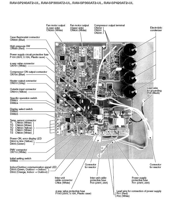
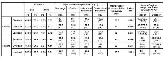
62 Example of RAV-SP420AT2-UL 62
63 Cassette Wiring Diagram 63

64 Cassette Indoor Board 64
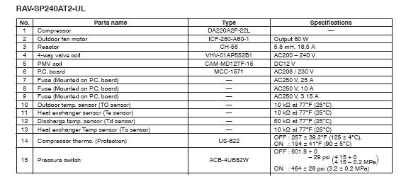
65 Cassette Specification of Electrical Parts 65
66 Under Ceiling Wiring Diagram 66

67 Under Ceiling Indoor Board 67
68 Under Ceiling Specification of Electrical Parts 68
69 High Wall Wiring Diagram 69
70 High Wall Indoor Unit Board 70
71 High Wall Specification of Electrical Parts 71
72 Example of RAV-SP240AT2-UL 72
73 Temperature Sensor Temperature Resistance Values 73
74 Test Run Setup Wired Remote a : Push button for more than 4 sec. b : TEST display in the panel. c : Select operation mode cooling or heating. d : Push button to start. e : After test run, push again ===> Goes into normal operation button and check TEST disappear. Temp control is unavailable / Fan speed is controllable. Compressor frequency is fixed as approximately Hz. Check code is available. Test run must be done only as TEST, otherwise the unit may be risky. After 60 minutes test mode will stop automatically. 74
75 Test Run Setup Wireless Remote 75
76 Test Run Setup Wireless Receiver Board (Cassette) a. Unit power OFF,and remove receiver part of wireless remote controller. b. Turn S003 _bit 1 OFF to ON. c. Reassemble receiver part to the unit,and Unit power ON. d. Select operation mode cooling or heating. e. Push button to start. f. After test run, push to stop and set S003 position to initial. ON Temp control is unavailable / Fan speed is controllable. Compressor frequency is fixed as approximately Hz. Check code is available. Test Run must be done only as test, otherwise the unit may be risky. After 60 min test mode will stop automatically S003 _bit 1 OFF to ON. 76
77 Test Run Setup High Walls Push TEMPORAY button for 10 seconds The unit enters forced cooling in about 3 minutes and a beep is heard Unit can be checked. Push the TEMPORARY button for 1 second to stop the forced cooling operation. To enter AUTO mode, push the TEMPORARY button for 1 second. 77

78 Monitor Function of Remote Control Cassettes and Under Ceiling a. Push + button simultaneously for more than 4 sec. b. Push button to select the set unit when group operation. The selected unit starts fan operation. c. Read the cycle temperature to pushing " TEMP SET " button. d. Push button to get to normal state. 1/10A * Does not apply to Under Ceiling units 78
79 Monitor Function of Remote Control High Wall Codes Setup procedure is the same as for the Cassettes and Under Ceiling units. 79
80 Support Functions Sizes 240 through 420 Two components to the board: Dip switches to setup either,select display list,or perform specific operations to help in servicing the unit LED s to display the requested information 80

81 Detail of D800 to D805 and SW803, SW800 SW800 LED D800 to D805 SW803 81
82 Dip Switch SW803 Setting List 82
83 General LED Display 83
84 Error Display All Dip switches OFF Current error Dip switch <1> only ON Previous error If an error is detected, any of the LED D800 to D804 can illuminate (Display 1) Push down SW800 for 1 sec., Display 1 changes into Display 2 Display 1 will be displayed again by pushing SW800 for 1 sec. or waiting for 2 minutes 84

85 Sensor, Current, Compressor Operation Frequency, PMV Opening Display 85
86 Dip Switch SW804 Specific Operation List Set the Dip Switches on SW804 Push SW801 for approximately 1 sec. The selected operation starts LED D805 (green) flashes Operation ends by: Pushing SW801 for 1 sec. Changing position of Dip switches Specified time of operation elapsed 86
87 Indoor Unit LED Display D501 (Red): Cassette, D02 (Red) Under Ceiling and High Walls Turns on when power is supplied to unit Flashes in 1 sec. interval when there is no EEPROM or writing in operation failed Flashes in 10 sec. interval during DISP mode Flashes in 2 sec. interval while setting of function D403 (Red) : Cassette, D203 (Red): Under Ceiling and High Walls Turns on when power to remote control is turned on D504 (Green) Cassette only Flashes 5 seconds in the first half communication with remote control Flashes with 0.2 interval for 5 seconds in the latter half of the communication between header unit and follower in group control D14 (Orange): Cassette only Flashes while receiving serial signal from the outdoor unit D15 (Green): Cassette only Flashes while sending a serial signal from the outdoor unit 87
88 Error Codes Displayed by Wired Remote Control (RBC-AMT32UL) Error happen! Unit number and check code flash on the remote controller panel Operation lamp flash ( green lamp ) According to the check code list, repair the error ==>Ref. service manual or quick reference card NOTE Simple remote controller ( RBC- AS21E ) can not display unit No. Only check code is displayed. Check code(alphabet + 2digitnumber) Unit No. 88
89 Recalling of Error History a.push + button simultaneously for more than 4 sec. b.the latest error code is displayed with as DN code No."01" c.push " TEMP SET "button to check the 2 nd ~4 th d.push button to get to a normal state. Error check TEMP set Monitoring error check This operation is only possible with a wired remote controller. It cannot be applied to other remote control units. Monitoring mode 89

90 Error Codes Displayed by Receiver Board (RBC-AX31U(W)-UL) Error happen Check the LED of indoor display panel (Receiving part) According to the state of the three lamps, judge check code. Refer service manual or quick reference card. Repair the error place Opera tion Timer Ready NOTE Only rough diagnosis can be available by indoor unit lamp. 90
 SW803: LED display by bit1 OFF and")
91 Error Codes Displayed by LED s On Outdoor Unit Board (RAV-SP240/300/360/420AT2-UL Models) SW803: LED display by bit1 OFF and ON LED SW803 SW800 91
92 Error Codes Displayed by Indoor Unit (Caused by Indoor Unit) 92
93 Error Codes Displayed by Indoor Unit (Caused by Indoor Unit) - Continued 93
94 Error Codes Displayed by Indoor Unit (Caused by Indoor Unit) - Continued 94
95 Error Codes Displayed by Indoor Unit (Caused by Outdoor Unit) 95
96 Error Codes Displayed by Indoor Unit (Caused by Outdoor Unit) - Continued 96
97 Error Codes Displayed by Indoor Unit (Caused by Outdoor Unit) - Continued 97
98 Error Codes Displayed by Indoor Unit (Caused by Outdoor Unit) - Continued 98
99 Error Codes Displayed by Indoor Unit (Caused by Outdoor Unit) - Continued 99
100 Trouble Shooting High Wall Units 100
101 Trouble Shooting High Wall Units - Continued 101
102 Trouble Shooting High Wall Units - Continued 102
103 Trouble Shooting High Wall Units - Continued 103
104 Trouble Shooting High Wall Units - Continued 104
105 Trouble Shooting Cassette and Under Ceiling Units 105
106 Trouble Shooting Cassette and Under Ceiling Units - Continued 106
107 Trouble Shooting Cassette and Under Ceiling Units - Continued 107
108 Trouble Shooting Cassette and Under Ceiling Units - Continued 108
109 Trouble Shooting Cassette and Under Ceiling Units - Continued 109
110 All Units Diagnostic Flow Charts [E01] Error 110
111 All Units Diagnostic Flow Charts [E09] Error All Units Diagnostic Flow Charts [E02] Error 111
112 High Wall Diagnostic Flow Charts [E04] Error 112
113 Cassette Diagnostic Flow Charts [E04] Error 113
114 Under Ceiling Diagnostic Flow Charts [E04] Error 114
115 All Units Diagnostic Flow Charts [E10] Error All Units Diagnostic Flow Charts [E08, L03, L07, L08] Error All Units Diagnostic Flow Charts [L09] Error 115
116 High Wall Diagnostic Flow Charts [E18] Error 116
117 Cassette and Under Ceiling Diagnostic Flow Charts [E18] Error 117
118 All Units Diagnostic Flow Charts [F10] Error 118
119 Cassette and Under Ceiling Diagnostic Flow Charts [P10] Error 119
120 High Wall Diagnostic Flow Charts [P12] Error 120
121 Cassette and Under Ceiling Diagnostic Flow Charts [P12] Error 121
122 All Units Diagnostic Flow Charts [F01] Error All Units Diagnostic Flow Charts [F02] Error 122
123 High Wall Diagnostic Flow Charts [F29] Error EEPROM error. Replace P.C. board. 123
124 Diagnostic Procedure Outdoor Units The error code display varies based on outdoor unit model (See below) RAV-SP180AT2-UL P.C. Board does not have LED indicators If LED indicators are desired, Application Control Kit (TCB-PCOS1UL) can be connected to unit Indoor unit /remote control displays some of the outdoor error codes RAV-SP240AT2-UL,RAV-SP300AT2-UL, RAV-SP360AT2-UL, RAV-SP420AT2-UL P.C. board does have LED indicators to display error codes Indoor unit/remote control displays some of the outdoor error codes 124
125 RAV-SP180AT2-UL [E04] Error 125
126 RAV-SP180AT2-UL [F04] Error 126
127 RAV-SP180AT2-UL [F06] Error 127
128 RAV-SP180AT2-UL [F08] Error 128
129 RAV-SP180AT2-UL [F12] Error 129
130 RAV-SP180AT2-UL [H01] Error 130
131 RAV-SP180AT2-UL [H02] Error 131
132 RAV-SP180AT2-UL [H03] Error 132
133 RAV-SP180AT2-UL [L29] Error 133
134 RAV-SP180AT2-UL [P03] Error 134
135 RAV-SP180AT2-UL [P04] Voltage Error 135
136 RAV-SP180AT2-UL [P04] High Pressure Switch Error 136
137 RAV-SP180AT2-UL [P05] Error 137
138 RAV-SP180AT2-UL [P19] Error 138
139 RAV-SP180AT2-UL [P22] Error 139
140 RAV-SP180AT2-UL [P26] Error 140
141 RAV-SP180AT2-UL [P29] Error 141
142 RAV-SP AT2-UL LED Display 142
143 RAV-SP AT2-UL [E04] Error 143
144 RAV-SP AT2-UL [F04] Error 144
145 RAV-SP AT2-UL [F06] Error 145
146 RAV-SP AT2-UL [F06] Error - Continued 146
147 RAV-SP AT2-UL [F07] Error 147
148 RAV-SP AT2-UL [F08] Error 148
149 RAV-SP AT2-UL [F12] Error 149
150 RAV-SP AT2-UL [F13] Error 150
151 RAV-SP AT2-UL [F15] Error 151
152 RAV-SP AT2-UL [F31] Error 152
153 RAV-SP AT2-UL [H01] Error 153
154 RAV-SP AT2-UL [H02] Error 154
155 RAV-SP AT2-UL [H03] Error 155
156 RAV-SP AT2-UL [H04] Error 156
157 RAV-SP AT2-UL [L10] Error 157
158 RAV-SP AT2-UL [L29] Error 158
159 RAV-SP AT2-UL [L29] Error - Continued 159
160 RAV-SP AT2-UL [P03] Error 160
161 RAV-SP AT2-UL [P04] Error 161
162 RAV-SP AT2-UL [P04] Error Continued 162
163 RAV-SP AT2-UL [P05] Error 163
164 RAV-SP AT2-UL [P07] Error 164
165 RAV-SP AT2-UL [P15] Error 165
166 RAV-SP AT2-UL [P19] Error 166
167 RAV-SP AT2-UL [P20] Error 167
168 RAV-SP AT2-UL [P22] Error 168
169 RAV-SP AT2-UL [P26] Error 169
170 RAV-SP AT2-UL [P29] Error 170
171 RAV-SP AT2-UL No Code Error 171
172 Trouble Shooting High Wall Units 172
173 Replacement Of Indoor P.C. Board P.C. boards include a nonvolatile memory chip (EEPROM) that contains the following Information: Model specific type information Capacity codes Factory set values Set data that was manually or automatically set when the indoor unit was installed When the board is replaced, the above information as well as the dip switches, and jumper wires need to be set. 173
174 Step 1 If possible read information from the EEPROM of the replaced board as follows: 1. Push SET, CL and TEST buttons (1) on the remote control simultaneously for more than 4 seconds. DN Code 10 is displayed, the indoor fan will run and the louvers will swing. 2. Change the DN code by pushing the up and down buttons for temperature control (3) to get to code The DN code ranges from 01 to FF 4. Write down the required values. 5. Push the Test button (4) to return to normal operation 174

175 Step 2 Set Dip Switches and Jumpers on Replacement Board and Install it Cassettes Under Ceiling High Wall Duplicate the settings from the board that is being replaced 175
176 Step 3 Turn On The Indoor Unit Auto addressing is initiated. The procedure requires approximately 5 minutes. It sets the System address =1, Indoor unit address =1, Group address = 0 For 1:1 systems this process can be interrupted by pushing the SET, CL, and TEST buttons simultaneously for more than 4 seconds. (in unit number ALL is displayed) 176
. 2. Select type by pushing the timer up and down buttons (4) and then pushing SET (5). 3.")
177 Step 4 Write the Set Data to EEPROM 1. Push SET, CL and TEST buttons on the remote control simultaneously for more than 4 seconds. DN Code 10 is displayed,the indoor fan runs and the louvers swing (6,5,1). 2. Select type by pushing the timer up and down buttons (4) and then pushing SET (5). 3. Change DN Code to 11 by pushing temperature up and down buttons (3). 4. Select capacity by pushing the timer up and down buttons (4) and then pushing SET (5). 5. Push TEST button (6) to return to normal display. 6. Write the contents that were read from the replaced board. If data could not be read, set up the unit again. 7. Write data by : Repeating 1 above Change DN Code to 01 by pushing temperature up and down buttons (3). Scroll through DN Codes, change values when necessary by pushing the timer up and down buttons (4) and then pushing SET (5) After completing the setup push TEST (6).
178 Replacement of Outdoor P.C. Boards 3 replacement boards are available RAV-SP180AT2-UL RAV-SP240AT2UL RAV-SP AT2UL Before board replacement: Set Dip switches Set Jumper wires 178
179 Dip switch settings Set all SW803 dip switched (LED indication) to OFF Set all SW804 dip switched (Special operation for service) to OFF 179
180 Set Jumper Wires Model switching Sizes 300 through 420 use the same board. Set up the board for the correct model by cutting the jumper wires per the table below. If board is not setup properly, L10 or L29 error will be displayed (wired control) and unit will not operate Unit setup 180

181 Refrigerant recovery function (Forced cooling operation mode) RAV-SP180AT2-UL 1. Turn on the power supply. 2. Using remote controller, set fan operation to indoor unit. 3. Fully close liquid side valve. 4. Pushing refrigerant recovery switch on terminal block, unit starts forced operation (Max 10 min), then refrigerant gas is recovered to outdoor unit through gas side valve. 5. After recovery is completed, close gas side valve, then push recover switch. 6. Forced cooling operation stops. 7. Turn off power supply. DANGER RAV-SP180AT2-UL Take care for electric shock, because control P.C.board is energized. 181

182 Refrigerant recovery function (Forced cooling operation mode) RAV-SP240/300/360/420AT2-UL DANGER Take care for electric shock, because control P.C.board is energized. 182
183 Forced Defrost Wired Remote Control Only 1. Remote has to be turned off 2. Push the TEST +SET+CL simultaneously for 4 seconds or more 3. If a group control is setup, push UNIT button to select the unit that requires defrost 4. Use the temperature UP and DOWN buttons to select DN Code 8C 5. Use timer UP and Down buttons to set code to 0001 (0000 set from factory) 6. Push SET button. (OK if indication is displayed) 7. Push TEST button to return to normal status. 8. Push ON/OFF button 9. Select HEAT mode 10. Defrost operation is initiated and will last for a maximum of 12 minutes 11. After defrost is terminated, the operation returns to HEAT MODE 12. If additional defrost is required, repeat steps 1 through
184 Cassettes Procedures
185 To remove the grille: Push the two slide latches away from you and drop the grille. Detach the hook (connected to the strap connected to the grille) from the corner If you wish to remove the grille, tilt the grille at a 45 angle and push upwards. To attach the grille: Reverse above steps.


186 Removing the control box cover Remove or drop the grille Remove screw A Loosen screw B (connected to a key hole) Drop the control box cover Control box cover can be removed by tilting it at an angle and sliding it out A wiring diagram is located on the inside of the cover Attaching the control box cover Reverse the above steps When putting the cover back make sure that the lip in the cover slides into the slot and the plastic pin is in the hole next to the B screw

187 Removing the corner cap The corner caps are removed to either adjust the unit (leveling) or to install the receiver for a wireless remote Pull knob of the corner cap downwards The corner cap is attached to the panel by a strap attached to a pin on the grille Replacing the corner cap If removed, connect the strap to the on the grille Insert the A claws into the horizontal slots Push the edges of the corner cap in place
188 Removing the grille and frame Remove the control box cover Remove the four corner caps Unplug the louver connector (CN510) from the control box and remove the wire from clamp Loosen the panel 4 fixing screws Slide the panel fixing bracket outlet Panel is held in place by tentative clip (bracket) shown on next slide

189 Push the tentative clips outwards and remove the panel. Attaching the grille and frame Orient the frame in the right direction. I.E. the louver motor connector is on the side of the control box. The frame has protruded plastic shapes that will fit into the unit to ensure proper orientation. Attach the frame using the tentative clips. The frame will be loosely connected to unit Reverse the steps outlined in removing the grille and frame section

190 Removing the control board Remove the grille Remove the cover of the control box Remove the following connectors from the board by unlocking the clip on the connector: CN510: Louver motor 20 wires CN34 : Float switch 3 wires CN504: Drain pump 2 wires CN101: TC sensor 2 wires CN102: TCJ sensor 2 wires CN104: Room temperature sensor 2 wires CN333: Fan motor power supply 5 wires CN334: Fan motor position detection 3 wires Unlock the 6 board clips (edge spacer) and remove the board Installing the control board Reverse the above steps

191 Remove the Drain Cap Remove the grille Loosen the three screws and turn the Drain Cap cover in the direction of the open arrow and remove the cap The cap cover is connected with a strap Loosen the cap by turning it approximately one turn in the direction of the open arrow Drain the water accumulated in the drain pan Turn the Drain Cap in the open direction and remove it completely Attaching the Drain Cap Insert the Drain Cap and turn it in the direction of the close arrow until it cannot be turned anymore. Drain pan marks align. Reverse the above steps

 and")

192 Removing the fan motor Remove the grille and frame Remove the control box cover Unscrew the power supply and remote control wires from terminal blocks Unplug the connectors from control board Remove the fixing screws A (qty 3) and B (qty 1) and remove control box Remove the fan motor, the TC, and TCJ sensor leads from the clamp on the bell mouth


193 Removing the fan motor continued Remove the fixing screws holding the fan guard. Fan guard hangs from a clip. Remove the fixing screws and remove the bell mouth Remove the nut cap by removing 2 screws Remove the turbo fan by removing the nut


194 Removing the fan motor continued Remove the motor lead holding bracket by unscrewing two screws Cut the bundling band and remove the wires from the clamp Unscrew the three fixing nuts to remove the motor Replacing the fan motor Reverse the earlier steps Note: When replacing the motor make sure: Wires are tight with no slack The D cut on the fan matches the D cut on the motor shaft
 from control board and remove wire from clamp")

195 Removing Drain pump Remove control box cover Remove Drain Cap Remove drain pump connector (CN504, white, 2P) from control board and remove wire from clamp Remove the 3 screws holding the pump to the bracket Pull out the connecting part of the drain pump and drain hose from the drain port and then take the drain pump out

196 Removing Drain pump continued Move the hose band away from the connecting part of the pump and remove the hose from the pump Free the connecting pump wires and remove the pump Installing Drain pump Using your hand, pass the pump wires back to the control board Reverse the steps outlined above


197 Removing Float Switch Remove bell mouth (see steps outlined in removing fan motor) Remove the fixing screw Installing Float Switch Reverse above steps
Owner s Manual RBC-AX32U(W)-E RBC-AX32U(WS)-E AIR CONDITIONER (SPLIT TYPE) Wireless remote controller kit. Model name: English.
-E RBC-AX32U(WS)-E AIR CONDITIONER (SPLIT TYPE) Wireless remote controller kit. Model name: English.") AIR CDITIER (SPLIT TYPE) Owner s Manual Wireless remote controller kit Model name: RBC-AX3U(W)-E RBC-AX3U(WS)-E Generic model name RBC-AX3U(W)-E Wireless remote controller model name WH-LSE Signal receiving
AIR CDITIER (SPLIT TYPE) Owner s Manual Wireless remote controller kit Model name: RBC-AX3U(W)-E RBC-AX3U(WS)-E Generic model name RBC-AX3U(W)-E Wireless remote controller model name WH-LSE Signal receiving
Pocket Quick Reference Guide On the TOSHIBA
 Pocket Quick Reference Guide On the TOSHIBA RBC-AMS51E / RBC-AMS54E Remote Controller Quick Reference Guide To assist service engineers working on Toshiba air conditioning equipment, there is a large quantity
Pocket Quick. Reference Guide. On the TOSHIBA RBC-AMS51E. Remote Controller
 Pocket Quick Reference Guide On the TOSHIBA RBC-AMS51E Remote Controller Quick Reference Guide To assist service engineers working on Toshiba air conditioning equipment, there is a large quantity of data
1:1 Model Connection Interface
 Air Conditioner Installation Manual 1:1 Model Connection Interface Model name: TCB-PCNT31TLUL Installation Manual Digital Inverter Air Conditioner 1 English Manuel d installation Climatiseur inverseur
OPERATION INSTRUCTIONS
 2018 Lennox Industries Inc. Dallas, Texas, USA OPERATION INSTRUCTIONS V0STAT52 Wireless Indoor Unit Controller CONTROLS 507459-04 05/2018 This manual must be left with the owner for future reference. IMPORTANT
RBC-AMT32E / RBC-AMS41E
 Pocket Quick Reference Guide On the TOSHIBA RBC-AMT32E / RBC-AMS41E Remote Controllers Quick Reference Guide To assist service engineers working on Toshiba air conditioning equipment, there is a large
Owner's Manual. Carrier TOSH BA REMOTE CONTROLLER FOR AIR CONDITIONER (SPLIT TYPE) Wireless remote controller kit TCB-AX21 UL
 Wireless remote controller kit TCB-AX21 UL") TOSH BA Carrier REMOTE CONTROLLER FOR AIR CONDITIONER (SPLIT TYPE) Owner's Manual Remote Controller Model name: Wireless remote controller kit TCB-AX21 UL Generic model name Wireless remote controller
TOSH BA Carrier REMOTE CONTROLLER FOR AIR CONDITIONER (SPLIT TYPE) Owner's Manual Remote Controller Model name: Wireless remote controller kit TCB-AX21 UL Generic model name Wireless remote controller
Wall mounted units. Please read carefully and thoroughly this manual before operating this unit and save it in a safe place for future reference.
 OWNERS' MANUAL REMOTE CONTROLLER Wall mounted units Please read carefully and thoroughly this manual before operating this unit and save it in a safe place for future reference. Warning. Be sure there
DESIGN & TECHNICAL MANUAL
 AIR CONDITIONER Duct type DESIGN & TECHNICAL MANUAL INDOOR ARYG72LHTA ARYG90LHTA OUTDOOR AOYG72LRLA AOYG90LRLA DR_AR012EF_03 2017.04.07 Notices: Product specifications and design are subject to change
7. PCB AND FUNCTIONS
 Contents. PCB AND FUNCTIS. Outdoor Unit Control PCB... - -. Outdoor Unit Control PCB CR-C0DXH... - -. Outdoor Unit FAN PCB FAN-C00DXH... - -. Outdoor Unit FAN PCB FAN-C0DXH... - -. Outdoor Unit Filer PCB
SERVICE Manual DUCT TYPE AIR CONDITIONER. (Cool) OUTDOOR UNIT INDOOR UNIT TYPE UDH4400G DH44ZAX IDH4400A DH44ZA1(A2) ADH4400G DH44ZA1(A2)
 OUTDOOR UNIT INDOOR UNIT TYPE UDH4400G DH44ZAX IDH4400A DH44ZA1(A2) ADH4400G DH44ZA1(A2)") DUCT TYPE AIR CONDITIONER (Cool) TYPE ADH4400G DH44ZA(A2) INDOOR UNIT IDH4400A DH44ZA(A2) OUTDOOR UNIT UDH4400G DH44ZAX SERVICE Manual AIR CONDITIONER CONTENTS. Product Specifications 2. Installation 3.
DUCT TYPE AIR CONDITIONER (Cool) TYPE ADH4400G DH44ZA(A2) INDOOR UNIT IDH4400A DH44ZA(A2) OUTDOOR UNIT UDH4400G DH44ZAX SERVICE Manual AIR CONDITIONER CONTENTS. Product Specifications 2. Installation 3.
Central Controller Operation & Installation Manual
 Central Controller Operation & Installation Manual YCZ-A004 CONTENT Function introduction of central controller... 1 Part info for central controller... 2 Page & Key Explanation... 4 Address Setting When
Operation 6035 ENGLISH PROG MENU
 Operation 6035 PROG MENU ENGLISH Operation 6035 Program button Time of day Day Time Slot Current Room Temperature Target Temperature Menu button PROG MENU FAN AUTO ON COOL OFF HEAT Fan Switch Touch Screen
R410A D2D_AU019E/
 R41A 2. : AUU18RCLX AUU24RCLX D2D_AU19E/ 27.6.11 2-1. FEATURE MODELS : AUU18RCLX / AOU18RLX AUU24RCLX / AOU24RLX FEATURES Easy maintenance The control box is easily accessible for maintenance work Wide
COMFORT CONTROL CENTER SERVICE INSTRUCTIONS
 USA SERVICE OFFICE Dometic Corporation 2320 Industrial Parkway Elkhart, IN 46516 574-294-2511 CANADA Dometic Corporation 46 Zatonski, Unit 3 Brantford, ON N3T 5L8 CANADA 519-720-9578 For Service Center
REMOTE CONTROLLER CS244-R OWNER S MANUAL
 OWNER S MANUAL REMOTE CONTROLLER Please read this Owner's Manual carefully before operation. Save this manual in a safe place for future reference. CS-R . After setting the TIMER, there will be a one-half
Installation Manual RB-RWS20-E. Lite-Vision plus Remote Controller. Model name: English
 Model name: RB-RWS20-E Read this manual before using the RB-RWS20-E remote controller. Refer to the supplied with the indoor unit for any installation instructions other than operations of the remote controller.
The PanasonicVRF Driver
 The PanasonicVRF Driver The PanasonicVRF driver interfaces to a Panasonic or Sanyo variable refrigerant flow (VRF) air conditioning system. Compatible VRF systems include Panasonic ECOi, ECO G, and Sanyo
Wireless Remote Controller Kit
 INSTALLATION MANUAL Wireless Remote Controller Kit LS BRC4C8 Read these instructions carefully before installation. Keep this manual in a handy place for future reference. This manual should be left with
Chilled Water REMOTE CONTROLLER OPERATION MANUAL MAN-O-CRC4AH intensity.mx
 Chilled Water REMOTE CONTROLLER OPERATION MANUAL intensity.mx MAN-O-CRC4AH-061 CONTENTS Remote Controller Specifications---------------------------------------1 Performance Features-----------------------------------------------------1
REMOTE CONTROL USER MANUAL QUICK CONNECT MINI-SPLIT
 COMFORT...BUILT TO LAST QUICK CONNECT MINI-SPLIT REMOTE CONTROL USER MANUAL FOR THE REMOTE CONTROL INCLUDED WITH YOUR PERFECT AIRE MINI-SPLIT AIR CONDITIONER Before using the remote control with your air
Removal and Installation8
 8 Screw Types 8-4 Top Cover Assembly 8-5 Left Hand Cover 8-6 Right Hand Cover 8-10 Front Panel Assembly 8-14 Left Rear Cover 8-15 Right Rear Cover 8-16 Extension Cover (60" Model only) 8-17 Media Lever
Installation and Operation Manual SPC1
 Installation and Operation Manual SPC1 BIA-SPC1 rev 5 Page 1 TABLE OF CONTENTS Page QUICK GUIDE DRAINAGE PUMP FLOATS CONNECTED TO PANEL 4-5 QUICK GUIDE DRAINAGE PUMP FLOAT CONNECTED TO PUMP 6-7 QUICK GUIDE
FX2-CHILLER. Digital Control. Operations Manual
 FX2-CHILLER Digital Control Operations Manual Micro Air Corporation Phone (609) 259-2636 124 Route 526 www.microair.net Allentown NJ 08501 Fax (609) 259-6601 Introduction: The FX2-CHILLER digital control
76 F. Ductless Split Air Conditioner. YR-E16b Wired Controller User Manual WARNING
 Ductless Split Air Conditioner YR-E16b Wired Controller User Manual Set temp. 76 F Indoor temp. 70 F Indoor humidity 32%RH Qty. online Standby Defrost Master Outdoor temp. 36 F Outdoor humidity 32%RH Mode
technical data Systems Individual control systems
 technical data Systems Individual control systems Individual control systems 17 1 Possible individual control systems...2 2 BRC2A51 - Simplified remote control Explanation of buttons and functions... 3
NOTE CONTENTS NOTE-CONTENTS
 NOTE 1.The outline figure on cover is for reference only, which may differ from what you purchased. 2. Make sure to read chapter PRECAUTIONS before you operate the air conditioner. 3. This manual is available
Single phase. Technical Support Division
 Single phase Technical Support Division 2014.12 CMV MINI VRF System - Control System 1 1. Outdoor Unit and Indoor Unit PCB 2. Communication System 3. Controllers 2 CMV MINI VRF System - Control System
OWNER S MANUAL WIRE CONTROLLER OF AIR CONDITIONER. MODEL: KJR-12B/DPBG(T)-E Brivis Part No:B026000
-E Brivis Part No:B026000") OWNER S MANUAL WIRE CONTROLLER OF AIR CONDITIONER MODEL: KJR-12B/DPBG(T)-E Brivis Part No:B026000 Brivis Climate Systems Pty Ltd Tel:1300 BRIVIS brivis.com.au Thank you very much for purchasing our product.
OWNER S MANUAL WIRE CONTROLLER OF AIR CONDITIONER MODEL: KJR-12B/DPBG(T)-E Brivis Part No:B026000 Brivis Climate Systems Pty Ltd Tel:1300 BRIVIS brivis.com.au Thank you very much for purchasing our product.
SINGLE. Technical Data Book Zone Control Systems
 SINGLE Technical Data Book Zone Control Systems Zone control system 2 I. Zone control system 1 Zone controller & remote temperature sensor 1. MWRZS00 / MWRZS10 / MRWTS 1) Features.... 4 2) Product specification...
ERV Control Interface Installation / Operation manual. TCB-IFVN1UL ERV Control Interface ENGLISH
 ERV Control Interface Installation / Operation manual Model name: For Commercial Use TCB-IFVN1UL ERV Control Interface ENGLISH Thank you for purchasing TOSHIBA / Carrier ERV Control Interface. This manual
IntesisBox PA-AW-MBS-1 v.2.0
 IntesisBox PA-AW-MBS-1 v.2.0 Modbus RTU (EIA485) Interface for Panasonic Aquarea series. User Manual Issue Date: 08/2014 r2.0 Order Code: PA-AW-MBS-1: Modbus RTU Interface for Panasonic Aquarea series
Air Conditioning Technical Data FVA-A > FVA71AMVEB > FVA100AMVEB > FVA125AMVEB > FVA140AMVEB
 Air Conditioning Technical Data FVA-A > FVA71AMVEB > FVA0AMVEB > FVA1AMVEB > FVA1AMVEB Indoor Unit FVA-A TABLE OF CONTENTS FVA-A 1 Features.............................................................
USER S MANUAL. DAS-G01 The Power of Tomorrow
 USER S MANUAL DAS-G01 The Power of Tomorrow Richmond Heights 2018 0 USER S MANUAL DAS-G01 The Power of Tomorrow Richmond Heights 2018 Page 1 USER'S MANUAL TABLE OF CONTENTS Page # 1.0 GENERAL INFORMATION...
Operation Guide CT32 ENGLISH
 Operation Guide CT32 The CT32 communicating thermostat operates via a high-quality, easy-to-use touch screen. To set or adjust your CT32, simply touch your finger firmly to the screen. The screen will
RBC-AMS55E-ES RBC-AMS55E-EN
 Wired Remote Controller Model name: RBC-AMS55E-ES RBC-AMS55E-EN Read this manual before using the RBC- AMS55E-ES, RBC-AMS55E-EN remote controller. Refer to the Installation Manual supplied with the indoor
CDD Carbon Dioxide Transmitter
 Introduction The OSA CO2 transmitter uses Infrared Technology to monitor CO2 levels within a range of 0 2000 ppm and outputs a linear 4-20 ma or 0-5/0-10 Vdc signal. The enclosure is designed to operate
Slim Ducted type. Contents MMD-AP 4SPH2UL MMD-AP0094SPH2UL MMD-AP0124SPH2UL MMD-AP0154SPH2UL MMD-AP0184SPH2UL
 E5-3I D-AP 4SP2U Slim Ducted type D-AP0074SP2U D-AP0094SP2U D-AP024SP2U D-AP054SP2U D-AP084SP2U Contents. Specifications 2. Dimensions 3. Center of gravity 4. Piping diagram 5. Wiring diagram 6. Electrical
Operation Guide CT100
 Operation Guide CT100 PG 1 The CT100 communicating Z-Wave thermostat operates via a high-quality, easy-to-use touch screen. To set or adjust your CT100, simply touch your finger firmly to the screen. The
WIRED REMOTE CONTROLLER OPERATION MANUAL
 WIRED REMOTE CONTROLLER OPERATION MANUAL BRCE6 Thank you for purchasing this product. This manual describes safety precautions required for the use of the product. Read this manual carefully and be sure
Operation Guide CT101
 Operation Guide CT101 PG 1 The CT101 communicating Z-Wave thermostat operates via a high-quality, easy-to-use touch screen. To set or adjust your CT101, simply touch your finger firmly to the screen. The
REMOTE CONTROLLER RG57 Function Selection Manual
 REMTE CNTRLLER RG57 Function Selection Manual www.mundoclima.com Thank you very much for purchasing our products. Please read this manual carefully before using the remote controller. RG57B2/BGE CL94774
IntesisBox ModBus RTU Fujitsu Air Conditioning
 IntesisBox ModBus RTU Fujitsu Air Conditioning Compatible with Domestic and VRF line air conditioners commercialized by Fujitsu User Manual 03/2019 r1.0 eng Intesis Software S.L.U. 2019 All Rights Reserved.
IntesisBox. v.0.1. User Manual Issue Date: 12/2017 r1.3 EN
 IntesisBox HS-RC-MBS-1 v.0.1 Modbus RTU (EIA-485) Interface for Hisense air conditioners. Compatible with commercial line of air conditioners commercialized by Hisense. User Manual Issue Date: 12/2017
Installation and Operation Manual DPC1
 Installation and Operation Manual DPC1 BIA-DPC1 rev 5 Page 1 TABLE OF CONTENTS Page QUICK GUIDE DRAINAGE PUMPS FLOATS CONNECTED TO PANEL 4-5 QUICK GUIDE DRAINAGE PUMPS FLOATS CONNECTED TO PUMPS 6-7 QUICK
To connect the AC adapter:
 Replacing the AC Adapter Replacing the AC Adapter 3 Plug the power cord into a wall outlet. The power indicator turns on. To connect the AC adapter: Connect the power cord to the AC adapter. Power indicator
Supplementary operating instructions for your air curtain system Controller TMC 500
 Supplementary operating instructions for your air curtain system Controller TMC 500 (Translation of the original) Serial number: Year: Please quote this number when contacting customer service! Date 08.04.2016
Quick Start Guide TS A
 Quick Start Guide TS 930 125-630A DANGER HAZARD OF ELECTRICAL SHOCK, EXPLOSION, OR ARC FLASH Read and understand this quick start guide before installing and operating the transfer switch The installer
This document describes the features and functional specifications of the ECONO3 air conditioner controller.
 TITLE : FUNCTIONAL SPECIFICATION FOR ECONO3 COOL REV : 01 DATE : MARCH 13, 2001. 1. INTRODUCTION 1.1 Scope of Document This document describes the features and functional specifications of the ECONO3 air
IntesisBox. v.2.5. User Manual Issue Date: 12/2017 r1.9 EN. Modbus RTU (EIA-485) Interface for Fujitsu air conditioners.
 Interface for Fujitsu air conditioners.") IntesisBox FJ-RC-MBS-1 v.2.5 Modbus RTU (EIA-485) Interface for Fujitsu air conditioners. User Manual Issue Date: 12/2017 r1.9 EN Order Codes: FJ-RC-MBS-1: Modbus RTU Interface for Fujitsu air conditioners
IntesisBox FJ-RC-MBS-1 v.2.5 Modbus RTU (EIA-485) Interface for Fujitsu air conditioners. User Manual Issue Date: 12/2017 r1.9 EN Order Codes: FJ-RC-MBS-1: Modbus RTU Interface for Fujitsu air conditioners
INTERFACE SPECIFICATION
 INTERFACE SPECIFICATION MODBUS CONVERTOR UTY-VMGX PART NO. 9708438030 Modbus is registered trademarks of Schneider Electric SA. LONWORKS is registered trademark of Echelon Corporation in the United States
3. Alignment and Adjustments
 3. 3-1 Test Mode How to Approach Test Mode You can approach the Test Mode by pressing the on/off switch of indoor unit for 5 seconds. on/off switch Test Mode Operation Option After installing the air conditioner,
EEDEN technical data. air conditioning systems. Individual Control Systems
 EEDEN08-204 technical data Individual Control Systems air conditioning systems 2e TABLE OF CONTENTS Individual control systems 1 Possible individual control systems.............................. 21 Survey................................................................
Zone Manager INSTALLATION MANUAL 40KMC KMQ QNC QNQ
 40KMC------301 40KMQ------301 40QNC------3 40QNQ------3 INSTALLATION MANUAL Installation manual This control system only operates with indoor units of the following models: 40KMC------301 and 40KMQ------301
WSHP-IOP-2 May Installation, Operation, and Programming. Tracer ZN510 Controller
 WSHP-IOP-2 May 1998 Installation, Operation, and Programming Tracer ZN510 Controller Literature History The Trane Company has a policy of continuous product improvement and it reserves the right to change
Incubator Shaker with Cooling
 A Geno Technology, Inc. (USA) brand name Incubator Shaker with Cooling Cat. No. BT923 1-800-628-7730 1-314-991-6034 info@btlabsystems.com Thanks for choosing BT Lab Systems Incubating Shaker. This operation
Brivis Touch. Owner s Manual
 Brivis Touch Owner s Manual Congratulations on purchasing a Brivis Touch Comfort Controller. This intelligent Controller can be used with a range of Brivis heating and cooling products. The Brivis Touch
Nearus USB2.0 Camera Manual NU-350-USB2PTZ-B
 Nearus USB2.0 Camera Manual NU-350-USB2PTZ-B Safety Tips Please read this manual carefully before installing the camera. Keep the camera away from violent vibration, physical stress, moisture, extreme
MiG2 CONTROLLERS. 2 & 4 Stage General Purpose Controllers, with Air-conditioning Facilities
 MiG2 CONTROLLERS 2 & 4 Stage General Purpose Controllers, with Air-conditioning Facilities The MiG2 controllers incorporate: 2 Inputs (Configurable as Resistive, 0 10V, 0 20mA or 4 20mA) 2 or 4 Relay Outputs
NetCommWireless. Quick Start Guide NTC-30 Series - Outdoor WiFi Router
 NetCommWireless Quick Start Guide NTC-30 Series - Outdoor WiFi Router NetCommWireless Let s get this show on the road You must be excited to get started with your Outdoor WiFi Router. If all goes to plan,
Operating Instruction
 Level and Pressure Operating Instruction VEGASWING 71 A Contents Contents Safety information... 2 1 Product description 1.1 Function and configuration... 3 1.2 Functional principle... 3 1.3 Technical data...
Installation & Operation Manual
 The 2nd-Generation Centralized Controller for Indoor Units: DTC-IHXR Installation & Operation Manual Please keep this specifications Manual properly. Read this specifications Manual carefully before using
Installation Manual. 1.Included Accessories. System Controller SC-201-6M INT. Requests to Installers *SHA8754 C*
 System Controller SC-201-6M INT Installation Manual Potential dangers from accidents during installation and use are divided into the following two categories. Closely observe these warnings, they are
DOT MATRIX PRINTER SP6000 SERIES
 DOT MATRIX PRINTER SP6000 SERIES Hardware Manual < Approval: CEL > Trademark acknowledgments SP6000 : Star Micronics Co., Ltd. Notice All rights reserved. Reproduction of any part of this manual in any
HIGH EFFICIENCY 15 and 17 SEER TWO STAGE HEAT PUMP ENVIRONMENTALLY SOUND R 410A REFRIGERANT. Min. Circuit Ampacity
 ENVIRONMENTALLY SOUND REFRIGERANT C4H(5, 7) Product Specifications HIGH EFFICIENCY 15 and 17 TWO STAGE HEAT PUMP ENVIRONMENTALLY SOUND R 410A REFRIGERANT 2, 3, 4, and 5 TONS SPLIT SYSTEM 208 / 230 Volt,
Written By: John Sutton
 Replacing the fan on your HP g7-2275 dx. Written By: John Sutton ifixit CC BY-NC-SA www.ifixit.com Page 1 of 20 INTRODUCTION Laptop cooking your lap? This guide will walk you through replacing your fan.
Technology is nothing without control
 46 Technology is nothing without control An innovative and complete range of integrated controls for application in the Toshiba VRF MiNi-SMMS, SMMS, SHRM systems ensures maximum comfort and excellent performance
Manual Control Unit GFCD 16
 Manual Control Unit 1400002_EN/04.2017 Index 1. Main features 3 2. Technical features 3 3. Installation guidelines 4 4. Preliminary checks 5 5. Electrical connections 5 6. Filter taps 5 7. Settings 6 8.
ES 4000 STANDARD. 1 General information Document Overview General description Introduction... 4
 Controller Instruction 1 General information ES 4000 STANDARD Printed Matter Number : 2946 7002 09 Applicable to : MB compressors Preliminary Operations: : Safety Instructions : General Persons Required
NEBULA X USER MANUAL. Redefining Tradition. Read carefully before using the device and save these instructions.
 NEBULA X Redefining Tradition USER MANUAL Read carefully before using the device and save these instructions. USER MANUAL Table of Contents...Page 1. An Introduction to Your New Nebula.... 2 2. Packaging
Chapter 2: Disassembly
 P370EM / P370EM3 Chapter 2: Overview This chapter provides step-by-step instructions for disassembling the P370EM / P370EM3 series notebook s parts and subsystems. When it comes to reassembly, reverse
EASTERN LABS. Instructions Model RM /25/2007. Operation. Junction Box Assembly. Different Types of Switch Installations
 EASTERN LABS Instructions Model RM-1205 04/25/2007 Operation Junction Box Assembly Different Types of Switch Installations Counter Mounting Suggestions Operation Total Counter Mix Counter Thru counter
Instruction Book. English. CITY MULTI Control System and Mitsubishi Mr. Slim Air Conditioners MA Remote Controller PAR-31MAA
 English CITY MULTI Control System and Mitsubishi Mr. Slim Air Conditioners MA Remote Controller PAR-31MAA Instruction Book Prior to use, thoroughly read the instructions in this manual to use the product
Keypad Lock. Operation and Service Manual. Order parts online
 Keypad Lock Order parts online www.follettice.com Operation and Service Manual 801 Church Lane Easton, PA 18040, USA Toll free (800) 523-9361 (610) 252-7301 Fax (610) 250-0696 www.follettice.com 00163345R00
USER MANUAL. INVERTER CHECKER Equipment for testing and diagnostic of the FUJITSU-GENERAL inverter split systems. UTQ-TOOLBOX contains:
 INVERTER CHECKER Equipment for testing and diagnostic of the FUJITSU-GENERAL inverter split systems USER MANUAL UTQ-TOOLBOX contains: UTQ-COMP - checker for DC compressors UTQ-DCFM - checker for DC fan
Installation, Start-up and Operating Instructions
 Installation, Start-up and Operating Instructions EVOLUTION SMART SENSOR FOR ZONING Cancels: NEW II ZONESMS-0-1 7-04 NOTE: Read the entire instruction manual before starting the installation. This symbol
Model HM-535 Power Supply Installation and Service Instructions
 Model HM-535 Power Supply Installation and Service Instructions 430-535 0104 2004 Heritage MedCall, Inc SENTRY INSTALLATION & SERVICE INSTRUCTIONS POWER SUPPLY UNIT Model HM-535 IMPORTANT SAFETY INSTRUCTIONS
DNG-200 LOW FOG GENERATOR USER MANUAL DNG-200 低煙機使用說明書
 DNG-200 LOW FOG GENERATOR USER MANUAL DNG-200 低煙機使用說明書 Read and save these insturctions 2008 Antari Lighting & Effects Ltd. User Manual Antari DNG-200 Low fog Generator Congratulations on the purchase
EL7060 Series SERVICE MANUAL
 EL7060 Series SERVICE MANUAL 1 TABLE OF CONTENTS 1 General description... 4 1.1 Exploded view... 5 2 ACCESSIBILITY... 5 2.1 Dust Bag Cover.. 7 2.2 Display Cover.8 2.3 PCB Display/Switch..9 2.4 Top Cover..10
Wired Controller Operation & Installation Manual
 Wired Controller Operation & Installation Manual YR-E16A CONTENT Parts and Functions... 1 Operation... 8 Wired Controller Wiring Instruction... 31 Please read this operation manual before using the air
SW-250 Wireless Control High Output Snow Machine User Manual
 SW-250 Wireless Control High Output Snow Machine User Manual English Français Deutsch 中文 2014 Antari Lighting and Effects Ltd. 1 2 ANTARI SW-250 SNOW MACHINE INTRODUCTION Thank you for choosing Antari
RAIN BIRD RC-4Bi, RC-7Bi, RC-1260Bi SERIES INSTRUCTION MANUAL
 RAIN BIRD RC-4Bi, RC-7Bi, RC-1260Bi SERIES INSTRUCTION MANUAL DESCRIPTION OF CONTROLS Refer to Figure 1 Figure 1 A. HOUR DIAL with 23 CYCLE START PINS The HOUR dial contains 23 pins for rescheduling automatic
Dell Inspiron XPS and Inspiron 9100 Service Manual
 Dell Inspiron XPS and Inspiron 9100 Service Manual Dell Inspiron XPS and Inspiron 9100 Service Manual Before You Begin Memory Module, Mini PCI Card, and Devices System Components Subwoofer Bluetooth Card
Free Energy Band RCC30U Room Temperature Controller for Four-pipe Fan Coil Unit
 Document No. 155-324 Free Energy Band RCC30U Room Temperature Controller for Four-pipe Fan Coil Unit Description Features Application Product Number Room temperature controller for four-pipe fan coil units.
ft Aspen Fir Item # Commercial ITEM Lights
 7.57.5 ft Aspen Fir Item #142027 Commercial ITEM Lights PARTS LIST A. BOTTOM B. LOWER MIDDLE C. UPPER MIDDLE D. TOP E. TREE STAND NUMBER OF PERSONS RECOMMENDED FOR ASSEMBLY: 2 SKU 142027 7.5 ASPEN FIR
The WPT- 800 Series kit includes the following components: WPT Universal wall bracket Mounting screws, #6 x 1 self-tapping (x2) CR123 batteries (x2)
 CR123 batteries (x2)") Wireless Pneumatic Thermostat- WPT-800 Series WPT Installation Manual 1 Overview The Cypress Envirosystems Wireless Pneumatic Thermostat (WPT) retrofits an existing pneumatic thermostat to provide Direct
Wireless Pneumatic Thermostat- WPT-800 Series WPT Installation Manual 1 Overview The Cypress Envirosystems Wireless Pneumatic Thermostat (WPT) retrofits an existing pneumatic thermostat to provide Direct
midi LOGGER 900 SERVICE MANUAL GL900-UM-251 GL900-UM
 midi LOGGER 900 GL900-UM-251 SERVICE MANUAL GL900-UM-251-01-9370 HISTORY OF REVISIONS No. Date issued Description of revision Page Edition 1 08.07.26 First Printing All 01 GL900-UM-251-9370 i TO ENSURE
Specifications Manual
 TCS-NET MODBUS Model name: TCB-IFMB640TLE Contents 1 System Overview... 2 2 RS 485 Communication Parameters... 3 3 Applied Function Codes... 3 4 Exception Response... 4 5 Counters and Registers... 4 6
DPM-3221 Digital DC Power Meter with data logging capability.
 Introduction DPM-3221 Digital DC Power Meter with data logging capability. User Manual As a digital DC power meter, it measures the real time DC Voltage (5-60V), DC Current (0-200 A with the correct shunt),
AE R6 July 2018 Electronic Unit Controller
 July 2018 Electronic Unit Controller TABLE OF CONTENTS Safety... 3 Safety Instructions... 3 Safety Icon Explanation... 3 Instructions Pertaining to Risk of Electrical Shock, Fire, or Injury to Persons...
LOW FOG 3000 FT USER MANUAL. Version: 1.0. ROBE Lighting s.r.o. Czech Republic
 LOW FOG 3000 FT USER MANUAL Version: 1.0 ROBE Lighting s.r.o. Czech Republic www.robe.cz LOW FOG 3000 FT Table of contents 1. Introduction 4 2. Safety instructions 4 3. Unpacking & Inspection 4 4. Setup
REMOTE CONTROLLER OWNER'S MANUAL AIR CONDITIONER OWNER'S MANUAL ATI/AOU-53HPR1 ATI/AOU-105HPS3 ATI/AOU-140HPS3
 OWNER'S MANUAL ОПИСАНИЕ ПУЛЬТА ДИСТАНЦИОННОГО УПРАВЛЕНИЯ AIR CONDITIONER REMOTE ROLLER ДЛЯ КОНДИЦИОНЕРА ILLUSTRATION OWNER'S MANUAL REMOTE CONTROLLER : ACI/AOU-35HPR1 ACI/AOU-53HPR1 ACI/AOU-71HPR1 ACI/AOU-105HPS3
MTP INSTRUCTION MANUAL
 MTP INSTRUCTION MANUAL Wireless Electricity Monitor Model MTP-3100 MTP Instruments Inc. Table of Content 1. Introduction Page 1 2. Safety and Maintenance Information Page 1 3. Features / Specifications
4-step Chiller and Heat Pump Controller
 4-step Chiller and Heat Pump Controller Technical Data Sheet GENERAL DESCRIPTION MODELS CODE MODEL DESCRIPTION MW324000 ECH 420 HEAT PUMP WITH 4 STEPS/ 2 CIRCUITS + MODBUS MW324005 ECH 420/V WITH SCREW
OPERATING INSTRUCTION
 OPERATING INSTRUCTION AUTORANGING MULTIMETER MAX Ω F C 10A MAX every 15 min. COM V SAFETY INFORMATION The following safety information must be observed to insure maximum personal safety during the operation
INSTALLATION MANUAL For authorized service personnel only.
 AIR CONDITIONER SIMPLE REMOTE CONTROLLER (WIRED TYPE) UTY-RSNUM INSTALLATION MANUAL For authorized service personnel only. English Français Español Contents. SAFETY PRECAUTIONS...2 2. ACCESSORIES...2 3.
Actuating Terminal Equipment Controller (ATEC) VAV with Reheat - Cooling and Heating, Application Application Note
 VAV with Reheat - Cooling and Heating, Application Application Note") Actuating Terminal Equipment Controller (ATEC) VAV with Reheat - Cooling and Heating, Application 2501 Application Note 140-1220 Building Technologies Table of Contents Overview... 4 Hardware Inputs...
Actuating Terminal Equipment Controller (ATEC) VAV with Reheat - Cooling and Heating, Application 2501 Application Note 140-1220 Building Technologies Table of Contents Overview... 4 Hardware Inputs...
UNIT CONTROLLER 7 (UC7) Operation & Installation. Hydronic Units
 Operation & Installation. Hydronic Units") UNIT CONTROLLER 7 (UC7) Operation & Installation Hydronic Units Date: 1 November 2012 Issue: 5 Page 1 of 17 Contents 1. Connections, hydronic unit... 3 2. Functions assigned to SSR1, SSR2 and AUX... 3
UNIT CONTROLLER 7 (UC7) Operation & Installation Hydronic Units Date: 1 November 2012 Issue: 5 Page 1 of 17 Contents 1. Connections, hydronic unit... 3 2. Functions assigned to SSR1, SSR2 and AUX... 3
Dryer. M720 Programming and Operation Manual. July 15, 2015 Revision 1.51
 Dryer M720 Programming and Operation Manual July 15, 2015 Revision 1.51 Contents 1 Important Safety Information 1 1.1 FOR YOUR SAFETY - CAUTION!............................. 1 2 Control Overview 2 2.1
impact INSTRUCTIONS LiteTrek 4.0 Monolight lighting equipment and accessories
 impact lighting equipment and accessories LiteTrek 4.0 Monolight INSTRUCTIONS Congratulations on your purchase of the Impact LiteTrek 4.0 Portable Monolight. Enjoy the many benefits of a portable strobe