FX2-CHILLER. Digital Control. Operations Manual
|
|
|
- Kerry Lee Watson
- 5 years ago
- Views:
Transcription
 259-2636 124 Route 526 www.microair.")
1 FX2-CHILLER Digital Control Operations Manual Micro Air Corporation Phone (609) Route Allentown NJ Fax (609)
2 Introduction: The FX2-CHILLER digital control operates onboard tempered water equipment to provide closed loop water temperature control. The FX2-CHILLER digital control is designed to operate with central type tempered water marine air-conditioning systems. Features include: High visibility Organic Light Emitting Diode display (OLED) offers superior visual characteristics compared to LCD displays. Variable brightness adjustment and automatic screen saver. Four position menu navigation switch featuring a joystick style interface with push on / push off control. The display is compatible with Vimar and Gewiss frames. Visual symbols enable the viewer to see the operating status at a glance. Easily programmed for customized operation. Built in options for fault protection help aid trouble diagnosis and prevent system damage. Universal 115/230 VAC 50/60 Hz power supply. FXII Chiller Revision: 05 March 25,
 Down Button 2.")


3 Before you start: 1. Applying power: When power is first applied, the display will show the software revision, and then return to the last state the unit was in when power was removed. On/Off Button Mode Select Button Up Button Service Button (Unmarked) Down Button 2. Joystick operation: The four position joystick may be tapped up, down, right, left or in the center to make changes to the operation of the control. Gently tap this switch to operate it. Excessive force will damage the switch. 3. Operating states: Pressing the joystick in the center will toggle between OFF and ON. When the display is OFF the display will appear dark**. When the display is ON, the display shows the operating screen**. See operating screens for an example. Switch between these states by pressing and releasing the On/Off button. **Unless screen saver is active. See screen saver for details. Operating Screens Screen Saver If no buttons are pressed for two minutes, the display will enter the screen saver mode. The display will dim and icons will scroll across the screen. To exit this mode, just tap any button. FXII Chiller Revision: 05 March 25,


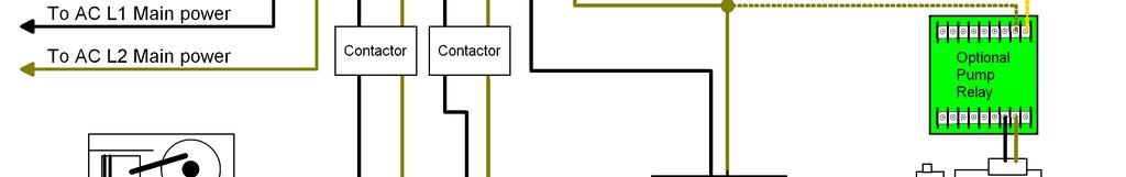
4 Operating Screen Water Inlet Temperature Water Outlet Temperature Temperature Set Point Operating Status Icon Heating or Cooling Mode Selection To change from heating to cooling or cooling to heating, tap the mode select button. Set the desired loop water temperature by tapping the up or down button. The system will provide cooling or heating as selected. Operation The control will automatically operate the circulating pump, sea water pump, compressor and heater or valve as necessary. Inlet temperature must be more than two degrees from the set point for operation to occur. In heat mode, temperatures must be below set point and in cool mode temperatures must be above the set point. Temperatures must be above 33 F for any operation. Operating output conditions are indicated in the icon at the center of the display. CW is the closed circulating water loop. When the pump is on, the icon will animate and show water flow in the system. If the flow switch opens, or the pump is off, the pipe will appear empty. This is the compressor symbol. When the compressor is running, the symbol will look like an operating piston. SW is the sea water pump. When the pump is on, the symbol will animate and show the pump operating and water flowing. When the sea water pump is off, the pipe will appear empty and the pump will not spin. This is the electric heat symbol. This symbol will appear in heat mode in place of the compressor if the optional electric heater is installed and selected in the programmable parameters. The animation will look like heat rising from the element when the heater is on. FXII Chiller Revision: 05 March 25,


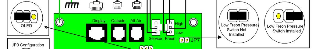
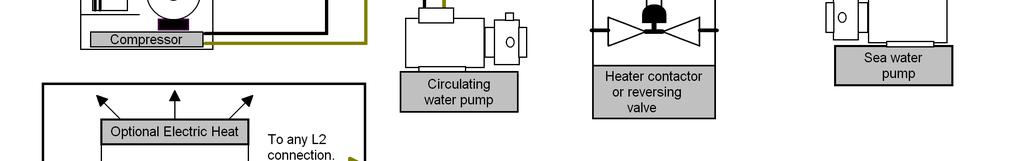
5 System Status Screen AC Line voltage System Current High Freon Pressure Switch (CLosed or OPen) Low Freon Pressure Switch (CLosed or OPen) System Frequency Flow Switch (CLosed or OPen) Viewing System Status In the ON state, press and hold the Mode select button for three seconds. The display will indicate AC line voltage, System current, AC Line frequency, and High and Low pressure switch status and Flow switch status. After one minute without a button press, the display will return to the operating screen. Viewing Fault History Fault message history may be viewed by pressing and holding the service button for three seconds with the display in the operating screen. Scroll from message to message by tapping the up and down buttons. The past eight fault messages, numbered from 1 to 8 can be viewed with the most recent numbered 1. Multiple faults of the same type will not be listed separately unless they occur more than one hour from the first fault. To clear the history log, the screen must show the operate screen. Press and hold the service button for 10 seconds. The history log will appear then the displayed fault will disappear indicating the log is cleared. Fault Messages The following fault messages will be shown on the display in the event of a problem. Compressor and electric heat operation is prevented for two minutes after a fault occurs. Following this two minute period, the control will restart in the last mode of operation. Pressing the on / off button twice will return the display to the operating screen but operation will not resume for two minutes. Repeated faults are an indication of a problem and should be checked by a qualified service person. LOCKOUT Four of the same faults occurred in less than 1 hour from the first fault. The display will show the fault that caused the lockout followed by the word LOCKOUT. Press the On/Off button twice on the display to clear a lockout. HIGH FREON PRESSURE: Indicates the high pressure switch connected to the High/Low Freon jack is open. If the switch resets, the compressor will restart within two minutes. LOW FREON PRESSURE: Indicates low pressure switch connected to the High/Low Freon jack is open for over 10 minutes. The LP jumper (JP7) on the FX2 power supply must be cut to enable this option. LOW AC VOLTAGE: The AC line voltage was below the voltage set in the programmable parameters for more than 10 minutes. FXII Chiller Revision: 05 March 25,
6 OVER CURRENT: The total system run current exceeded the limit set in the programmable parameters. Systems may start with currents exceeding the limit but must be below the limit within two seconds after the start of the compressor. FREEZE FAULT: The closed circulating loop water temperature at the water outlet sensor is below 34 F. This fault causes an immediate lockout for system protection. FLOW SWITCH OPEN: The closed circulating water loop flow switch connected to the service input is open for more than 10 seconds. When this fault occurs, all outputs will shut down for two minutes then restart. SENSOR TROUBLE WATER IN: The sensor connected to the ALT AIR jack (Loop water in) has failed or is disconnected. SENSOR TROUBLE WATER OUT: The sensor connected to the OUTSIDE jack (Loop water out) has failed or is disconnected. HIGH LIMIT: Closed circulating loop water outlet temperature has exceeded the limit set in the programmable parameters. KLIXON OPEN: EasyStart has detected a problem with the compressor most likely an open compressor overload protector. EasyStart will wait 3 minutes before attempting a restart. Systems without EasyStart should set the program parameter Starter Present to NO to prevent this error. COMPRESSOR STALLED: EasyStart has detected a problem with the compressor most likely a stalled compressor. EasyStart will wait 3 minutes before attempting a restart. Systems without EasyStart should set the program parameter Starter Present to NO to prevent this error. FXII Chiller Revision: 05 March 25,
7 Program Parameters: There are eleven programmable parameters with their factory defaults described in this section. The table below defines the parameter descriptions along with the permitted values and default settings. To enter the program mode first put the unit in the off state. Press and hold the joystick in the center for 3 seconds. Use the fan button to advance to the next parameter and the mode button to go back to the last parameter. Use the up and down buttons to change the parameters value. Exit the program mode when finished by pressing and releasing the On/Off button or wait 60 seconds for the display to exit. Note: program mode can also be entered by pressing the following sequence of buttons: Mode, Up, Down, Mode in the off mode. Description Default Value Display brightness 15 4=Minimum 15=Maximum Screen Saver Brightness 4 0=Minimum 8=Maximum Staging Delay 15 or 45* Seconds Current Limit Amps (0 is disabled) Low AC Line Detection Off or VAC High Limit Threshold F System Units F F or C Cycle Sea Pump Cycled Sea Pump Cycled or Continuous Reverse Cycle Heat Reverse Cycle Heat Electric Heat or Reverse Cycle Heat Purge Air in System No Yes or No Starter Present No Yes or No Reset Parameters No No or Yes If JP8 is removed, Staging Delay default will be 45 seconds. Parameter description: o Display brightness: Display brightness can be set from 4 (dim) to 15 (bright) to suit room lighting. Brightness will change as the number is changed. o Screen saver brightness: Number values from 0 (dim) to 8 (bright) can be set to suit room brightness. The unit will operate as described in the screen saver section. o Staging delay: The compressor staging delay is provided for multi system installations where more than one system is operating from the same power source. Set the Staging delays at different intervals so only one compressor starts at a time when power is applied. o Current limit: The system current limit can be set from 0 to 35 Amps maximum running current. Systems may start at higher FXII Chiller Revision: 05 March 25,
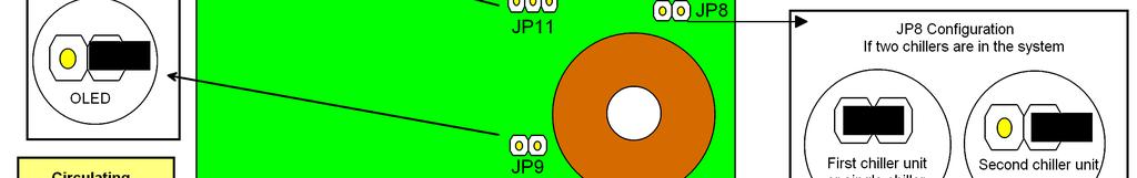
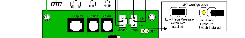
8 currents but running currents must be less than the set point. To disable this fault set the limit to 0. o Low AC line detection: When set, if the AC line voltage remains below the set value for 10 minutes, the control will turn off the compressor or heater and indicate Low AC. Voltages may be set between 75 and 100 VAC for 120 volt systems, and VAC for VAC systems. o High Limit Threshold: Set this parameter to monitor water outlet temperature. Temperatures may be selected between 100 F and 135 F. o System units: Degrees Fahrenheit ( F) or degrees Celsius ( C) can be selected o Cycled Sea Pump: This setting will turn on the sea pump with the compressor. This parameter may be changed to run the Sea Pump continuously. o Electric Heat/ Reverse Cycle Heat: Set this parameter only if the system is equipped with an electric heater. If the heater current will exceed 10 Amps, a contactor must be connected to the valve output to use this feature. o Purge Air in System: This parameter allows the user to operate the circulating pump for one hour while the system is being filled so air can be removed. Set the parameter to YES and press the On/Off button. The display will go blank then the screen saver will appear with PURGING AIR on the screen. The circulating loop water pump will run for 1 hour then turn off. To exit this function, press the On/Off button. Flow faults are disabled while Purge Air is active. Flow switch status may be viewed in the system status screen. See Viewing System Status for details. o Starter Present: Set this parameter to YES only if the EasyStart option board is installed on top of the FXII power supply. This option must be set for No for ALL other systems including EasyStart systems where the EasyStart option board is NOT installed on the FXII power supply such as those systems with EasyStart in an external box. o Reset parameters: To reset all parameters to factory defaults, select YES and then exit the program mode by pressing the joystick center button. The display will show EEPROM RESET then the display will go blank indicating the unit is OFF. Staging two compressors in a system: In some applications, two compressors may be necessary to handle the cooling or heating load. On these systems, remove jumper JP8 from one of the two power supplies. (see Wiring Diagram and Configuration for jumper location details). With JP8 removed, the second unit will operate at a different default set point and staging delay. Defaults: JP8 In: Cool 42 F, Heat 110 F, Staging Delay 15 Seconds JP8 Out: Cool 44 F, Heat 108 F, Staging Delay 45 Seconds FXII Chiller Revision: 05 March 25,
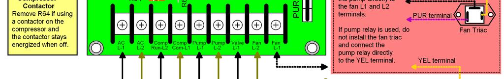
9 Specifications Set point range Cool Mode 38 F-58 F or 3.3 C-14.4 C Heat Mode 95 F to 120 F or 35 C to 48.9 C Sensor accuracy 2 F at 77 F Low voltage limit 115 VAC units Low voltage limit 230 VAC units Line voltage limit Frequency Fan output MAX (Connect to Sea Water Pump) Valve output MAX (Connect to optional electric heater) Circulating Pump output MAX Compressor output 75VAC 175VAC 240VAC 50 or 60 Hz 4 Amps 10 Amps ¼ HP at 115 VAC ½ HP at 230 VAC 1HP at 115 VAC 2HP at 230 VAC Minimum operating temperature 0 F Maximum operating temperature 180 F Maximum RH conditions Maximum length of the display cable Maximum length of the sensor cable 99% Non-condensing 75 Feet 50 Feet FXII Chiller Revision: 05 March 25,
10 PCB F and Earlier FXII Chiller Revision: 05 March 25,
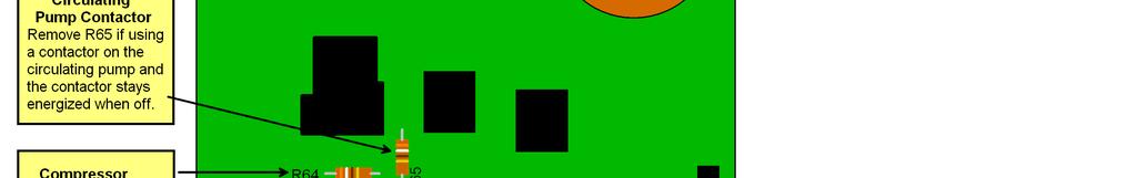
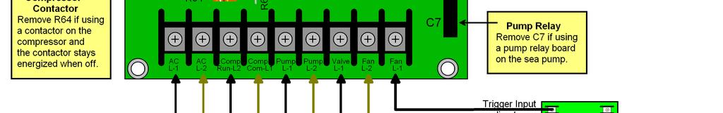
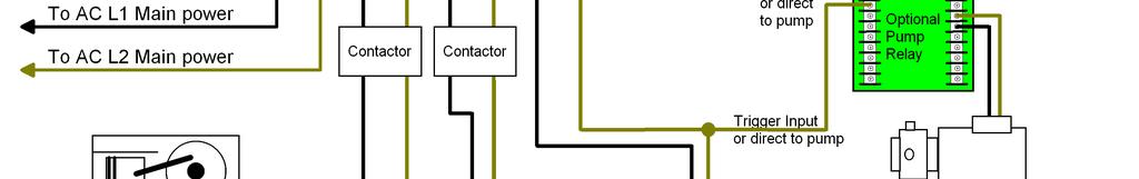
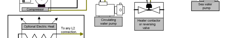
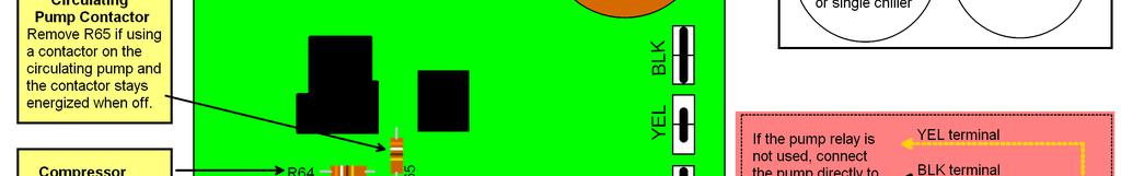
11 PCB G and later wiring diagram and configuration FXII Chiller Revision: 05 March 25,
12 Updates: From To Reason Rev 3 Rev 4 Add parameter in FRM278B16 for Starter Present. Rev 4 Rev 5 Add fault descriptions for EasyStart and update wiring for 360 rev G boards COPYRIGHT 2008 Micro Air Corporation, All Rights Reserved No part of this publication may be reproduced, translated, stored in a retrieval system, or transmitted in any form or by any means electronic, mechanical, photocopying, recording or otherwise without prior written consent by Micro Air Corporation. Every precaution has been taken in the preparation of this manual to insure its accuracy. However, Micro Air Corporation assumes no responsibility for errors and omissions. Neither is any liability assumed nor implied for damages resulting from the use or misuse of this product and information contained herein. FXII Chiller Revision: 05 March 25,
FX 2 Instruction Manual
 FX 2 Instruction Manual Climma Compact Version Annapolis MD USA 301 352 6962 info@veco-na.com Introduction: The FX2-DX digital controller operates onboard air conditioning equipment to provide room temperature
ARCTIC AIR DC OLED. Digital Control Operations Manual
 ARCTIC AIR DC OLED Digital Control Operations Manual Micro Air Corporation Phone (609) 259-2636 124 Route 526 WWW.Microair.net Allentown NJ 08501 Fax (609) 259-6601 Before you start: 1. Applying power:
FX-2 Control Board ASY-360-XXX Setup and Configuration Guide
 FX-2 Control Board ASY-360-XXX Setup and Configuration Guide Micro Air Corporation Phone (609) 259-2636 124 Route 526. WWW.Microair.net Allentown NJ 08501 Fax (609) 259-6601 Table of Contents Introduction...
INTRODUCTION. FX-1 Operations Manual. Standard Features. Optional Features. Read This Manual Completely Before Proceeding!
 INTRODUCTION The FX-1 Control is designed for use with all direct expansion, reverse cycle air conditioning systems. FX-1 has a universal power supply that operates on 115, 230, 50 or 60 Hz AC power. FX-
FX-2 Control Board ASY-360-XXX Setup and Configuration Guide
 FX-2 Control Board ASY-360-XXX Setup and Configuration Guide Micro Air Corporation Phone (609) 259-2636 124 Route 526. WWW.Microair.net Allentown NJ 08501 Fax (609) 259-6601 Table of Contents Introduction...
R & D SPECIALTIES SERIES 100 RO CONTROLLER USERS MANUAL. 2004, by R & D Specialties, Inc. All Rights Reserved.
 R & D SPECIALTIES 2004, by R & D Specialties, Inc. All Rights Reserved. No part of this document may be copied or reproduced in any form or by any means without the prior written permission of R & D Specialties.
AirNet. CAN to Ethernet Adapter Setup Manual
 AirNet CAN to Ethernet Adapter Setup Manual Micro Air Corporation Phone (609) 259-2636 124 Route 526 www.microair.net Allentown NJ 08501 Fax (609) 259-6601 Note to installers: These manual requires making
MiG2 CONTROLLERS. 2 & 4 Stage General Purpose Controllers, with Air-conditioning Facilities
 MiG2 CONTROLLERS 2 & 4 Stage General Purpose Controllers, with Air-conditioning Facilities The MiG2 controllers incorporate: 2 Inputs (Configurable as Resistive, 0 10V, 0 20mA or 4 20mA) 2 or 4 Relay Outputs
AirNet CAN Bus Implementation Revision /6/2018
 AirNet CAN Bus Implementation Revision 8.07 7/6/2018 Table of Contents 1. CAN Implementation... 3 2. Standard Types... 4 3. HVAC Command 0x3F0 (1008.)... 5 4. HVAC Status 0x3E0 (992.)... 7 5. HVAC Supplemental
TEMPERATURE CONTROLLER 2 HEAT/ 2 COOL with Digital Room Temperature Display. Made in Australia 100% Australian Owned Company
 TEMPERATURE CONTROLLER 2 HEAT/ 2 COOL with Digital Room Temperature Display HTC 5 Features Australian Made and designed Power can be either 24V or 240V AC 10 Amp (Resistive) Potential free relay contacts
OK - Functions of the buttons. = "Arrow up" = ON / OFF. = Enter. = Temperature. ="Arrow down" = Preset time / Start time.
 1601-13 + OK - Functions of the buttons = ON / OFF = Temperature = Preset time / Start time = Heating time = Saunalight = Fan + OK - = "Arrow up" = Enter ="Arrow down" 314 SYRA 6 C OPERATION OF DIGI 1
4-step Chiller and Heat Pump Controller
 4-step Chiller and Heat Pump Controller Technical Data Sheet GENERAL DESCRIPTION MODELS CODE MODEL DESCRIPTION MW324000 ECH 420 HEAT PUMP WITH 4 STEPS/ 2 CIRCUITS + MODBUS MW324005 ECH 420/V WITH SCREW
Millennium Simplicity Elite Parameter Points and Quirks
 Millennium Simplicity Elite Parameter Points and Quirks How to access, view and change parameter settings Program Button Test Reset UP Alarms Change Data Address Down 1. Push the Program button once. The
Wiring Diagrams UNITS WITH STARTING SERIAL NUMBER 3507Q
 AQUASNAP 30RB060-390 Air-Cooled Liquid Chillers with COMFORTLINK Controls 60 Hz Wiring Diagrams UNITS WITH STARTING SERIAL NUMBER 3507Q INDEX* POWER SCHEMATICS 30RB Unit Size Voltage Figure Number Label
This document describes the features and functional specifications of the ECONO3 air conditioner controller.
 TITLE : FUNCTIONAL SPECIFICATION FOR ECONO3 COOL REV : 01 DATE : MARCH 13, 2001. 1. INTRODUCTION 1.1 Scope of Document This document describes the features and functional specifications of the ECONO3 air
pco 3 Controller User Manual ASPX Digital Scroll, Air Packaged Chiller For Version MCDSV_A02
 pco 3 Controller User Manual ASPX Digital Scroll, Air Packaged Chiller For Version MCDSV_A02 pco 3 Controller User Manual Introduction The Airstack Chiller is a modular air-cooled chiller composed of
Wiring Diagrams DIAGRAM INDEX. POWER SCHEMATICS Unit 30GXN,R Voltage Figure Number
 30GXN,R Sizes 080-528 Air-Cooled Chillers with ComfortLink Controls 50/60 Hz Wiring Diagrams DIAGRAM INDEX POWER SCHEMATICS Unit 30GXN,R Voltage Figure Number Label Diagram No. 30GX 080-178* ALL 1 505429
ADVANCED TECHNICAL MANUAL AAC1 SMALL SYSTEM CONTROL CONSOLE. Redefine your comfort zone.
 ADVANCED TECHNICAL MANUAL AAC1 SMALL SYSTEM CONTROL CONSOLE ATM ACC1 Table of Contents Safety Precautions... 3 Overview... 4 Specifications... 4 Installation... 5 Control Console Operation... 9 2 Advanced
32MP Gateway. Overview and Configuration Manual
 32MP Gateway Overview and Configuration Manual 32MP Gateway Overview and Configuration Manual This document is the property of Carrier Corporation and is delivered on the express condition that it is not
Component Troubleshooting
 Component Troubleshooting 7 PLC Power Supply and CPU Troubleshooting CPU Indicators The DL250 CPU has indicators ( Status LED s ) on the front to help you diagnose problems with the system. The table below
IntesisBox. v.0.1. User Manual Issue Date: 12/2017 r1.3 EN
 IntesisBox HS-RC-MBS-1 v.0.1 Modbus RTU (EIA-485) Interface for Hisense air conditioners. Compatible with commercial line of air conditioners commercialized by Hisense. User Manual Issue Date: 12/2017
Xpander Desktop Elite Gen 3 User Guide
 Xpander Desktop Elite (see the image at the right) is a portable PCI Express (PCIe) expansion enclosure that enables connection of graphics processing units (GPUs) or other controllers to a host computer.
Brivis Touch. Owner s Manual
 Brivis Touch Owner s Manual Congratulations on purchasing a Brivis Touch Comfort Controller. This intelligent Controller can be used with a range of Brivis heating and cooling products. The Brivis Touch
Service Bulletin SB685. Date: 8/18/2017 TriPac EVOLUTION Communications Update Bulletin Location: TSA Info Central\Service Bulletins
 Service Bulletin SB685 Date: 8/18/2017 Subject: TriPac EVOLUTION Communications Update Bulletin Location: TSA Info Central\Service Bulletins Units: All TriPac EVOLUTION Summary: This bulletin updates and
BB5-Lite TECHNICAL MANUAL
 BB5-Lite TECHNICAL MANUAL Product Support 1800 354 434 CC - BB5 - LITE LITE with Plug & Play technology www.blackbox.net.au Designed by IAS in Brisbane Made in Australia Product Support 1800 354 434 www.ias.net.au
DEKKER KNOWLEDGE DATABASE KNOWLEDGE IS POWER
 DEKKER KNOWLEDGE DATABASE For Use with DEKKER Vacuum Systems Equipped with the DEKKER Controller Each Vmax system is tested and checked at the factory prior to shipment to ensure trouble-free operation.
Dryer. M720 Programming and Operation Manual. July 15, 2015 Revision 1.51
 Dryer M720 Programming and Operation Manual July 15, 2015 Revision 1.51 Contents 1 Important Safety Information 1 1.1 FOR YOUR SAFETY - CAUTION!............................. 1 2 Control Overview 2 2.1
Product Manual 8330GMX
 Product Manual 8330GMX Register Access Panel with Modbus Interface Quartech Corporation 15923 Angelo Drive Macomb Township, Michigan 48042-4050 Phone: (586) 781-0373 FAX: (586) 781-0378 Email: Sales@QuartechCorp.com
INSTRUCTION MANUAL STATION CONTROLLER SC1000 MOTOR PROTECTION ELECTRONICS, INC.
 INSTRUCTION MANUAL STATION CONTROLLER SC1000 MOTOR PROTECTION ELECTRONICS, INC. 2464 Vulcan Road, Apopka, Florida 32703 Phone: (407) 299-3825 Fax: (407) 294-9435 Revision Date: 9-11-08 Applications: Simplex,
Product Manual Pushbutton Station for Modicon Programmable Controller MODBUS Interface
 Product Manual 8652 Pushbutton Station for Modicon Programmable Controller MODBUS Interface Quartech Corporation 15923 Angelo Drive Macomb Township, Michigan 48042-4050 Phone: (586) 781-0373 FAX: (586)
INSTALLATION, OPERATION & MAINTENANCE CRFF Series Wall Control Console. ECM Motors. ACC1-25 (Part # ) Revision:
 Revision:") INSTALLATION, OPERATION & MAINTENANCE CRFF Series Wall Control Console ACC1-25 (Part # 63971-002) ECM Motors Revision: 10.01.13 Page: 2 of 11 Table of Contents Safety Precautions...3 Overview...3 Specifications...4
INSTALLATION, OPERATION & MAINTENANCE CRFF Series Wall Control Console ACC1-25 (Part # 63971-002) ECM Motors Revision: 10.01.13 Page: 2 of 11 Table of Contents Safety Precautions...3 Overview...3 Specifications...4
Temperature controller Ducted systems
 2 725 Temperature controller Ducted systems Standard model without zoning functions RRV851 Multifunctional controller used for central control of ducted HVAC systems in combination with a QAX850 master
MODELS: STEAM FIRED YPC-ST-14SC & YPC-ST-16SL Thru YPC-ST-19S
 Supersedes: 155.19-W1 (407) Form: 155.19-W1 (812) TWO-STAGE ABSORPTION CHILLERS WIRING DIAGRAMS CONTRACTOR ORDER NO. JCI CONTRACT NO. JCI ORDER NO. PURCHASER JOB NAME LOCATION ENGINEER REFERENCE DATE APPROVAL
HCS-3600 / 3602 / 3604 Laboratory Grade & High RFI Immunity Switching Mode Power Supply with Rotary Encoder Control
 HCS-3600 / 3602 / 3604 Laboratory Grade & High RFI Immunity Switching Mode Power Supply with Rotary Encoder Control 1. INTRODUCTION User Manual This family of efficient, upgraded SMPS with small form factor,
The PanasonicVRF Driver
 The PanasonicVRF Driver The PanasonicVRF driver interfaces to a Panasonic or Sanyo variable refrigerant flow (VRF) air conditioning system. Compatible VRF systems include Panasonic ECOi, ECO G, and Sanyo
TECHNICAL MANUAL WATER 300 C 5300 CV/06-00 GB
 T E C H N I C A L M A N U A L TECHNICAL MANUAL C 5300 CV/06-00 GB GB The information contained in this document may be modified without prior notice and is in no way binding, even implicitly, for CLIMAVENETA.
IPS INTELLIGENT PUMP STARTER
 IPS INTELLIGENT PUMP STARTER The IPS Intelligent Pump Starter features SMARTSTART motor protection, integrated electronic pump protection overload, and power metering and data logging options. Ø & Ø, 0/60
UNIT CONTROLLER 7 (UC7) Operation & Installation. Hydronic Units
 Operation & Installation. Hydronic Units") UNIT CONTROLLER 7 (UC7) Operation & Installation Hydronic Units Date: 1 November 2012 Issue: 5 Page 1 of 17 Contents 1. Connections, hydronic unit... 3 2. Functions assigned to SSR1, SSR2 and AUX... 3
UNIT CONTROLLER 7 (UC7) Operation & Installation Hydronic Units Date: 1 November 2012 Issue: 5 Page 1 of 17 Contents 1. Connections, hydronic unit... 3 2. Functions assigned to SSR1, SSR2 and AUX... 3
Installation and Operation Manual SPC1
 Installation and Operation Manual SPC1 BIA-SPC1 rev 5 Page 1 TABLE OF CONTENTS Page QUICK GUIDE DRAINAGE PUMP FLOATS CONNECTED TO PANEL 4-5 QUICK GUIDE DRAINAGE PUMP FLOAT CONNECTED TO PUMP 6-7 QUICK GUIDE
Smartstart Control Module
 Smartstart TECHNOLOGY What is Smartstart? The patented Smartstart control module is an integrated, seamless solution that incorporates operator control, superior motor protection, and automation system
FC-DIN DIN-Rail Mount Fan Speed Controller
 Page 1 of 7 FC-DIN DIN-Rail Mount Fan Speed Controller Features: Benefits: Volume or velocity reduction Suitable for supply & extract systems Minimum and maximum speed adjustment DIN-Rail mountable Configurable
Viconics VT76x6W Water-source Heat Pump Controllers Engineering Guide Specification
 Viconics VT76x6W Water-source Heat Pump Controllers Engineering Guide Specification General The VT76xxW series is designed for single-stage and multi-stage control of water source heat pumps with dedicated
COMFORT CONTROL CENTER SERVICE INSTRUCTIONS
 USA SERVICE OFFICE Dometic Corporation 2320 Industrial Parkway Elkhart, IN 46516 574-294-2511 CANADA Dometic Corporation 46 Zatonski, Unit 3 Brantford, ON N3T 5L8 CANADA 519-720-9578 For Service Center
CommandCenter Operator Panel
 CommandCenter Operator Panel Introduction This document describes the different features of the Operator Panel (local or remote) that is used with the Seresco units. Startup Screens When the unit start
VLT 2800 DRIVE SPECIFICATIONS
 VLT 2800 DRIVE SPECIFICATIONS Drive Input Power Input voltage 3 phase... 200 through 240, or 380 through 460; 3-phase all ratings 200 through 240, 1-phase through 2 HP Input voltage range for full output...
Installation and Operation Manual DPC1
 Installation and Operation Manual DPC1 BIA-DPC1 rev 5 Page 1 TABLE OF CONTENTS Page QUICK GUIDE DRAINAGE PUMPS FLOATS CONNECTED TO PANEL 4-5 QUICK GUIDE DRAINAGE PUMPS FLOATS CONNECTED TO PUMPS 6-7 QUICK
DM-918 OPERATIONS MANUAL AUTORANGING MULTIMETER
 DM-918 OPERATIONS MANUAL AUTORANGING MULTIMETER SAFETY INFORMATION The following safety information must be observed to ensure maximum personal safety during the operation of this meter: This meter is
SMARTSTART MOTOR STARTERS
 SMARTSTART MOTOR STARTERS MCG WWW.MCG-USA.COM 1 AT A GLANCE Covers all line voltages from 200-600V AC, single or three phase Transformer supplies a 24V AC coil voltage, no matter the line voltage 12V AC/DC
ESC 201. Installation and Operating Instructions Manual. SG Jan 2015
 ESC 201 Installation and Operating Instructions Manual SG-0002-03 Jan 2015 Table of Contents 1.0 FUNCTIONS... 5 2.0 FEATURES... 5 3.0 ESC 201 DESCRIPTION... 6 4.0 GENERAL OPERATIONS... 6 4.1 MANUAL MODE
Series SD-3PB Digital THERMOSTAT + TIMER
 SD-3PB Thermostat and Interval Timer in one Unit. This microcomputer based controller consists of two sections: The Digital Timer and Digital Thermostat, working together to control the power switched
User Guide. FreeCool : Free Cooling unit V1.1 ENGY-SVU001A-GB
 User Guide FreeCool : Free Cooling unit V1.1 ENGY-SVU001A-GB Table of Contents Introduction...3 General features...4 User interface...5 Top display area... 5 Bottom display area... 5 Main display area...
BACVIEW MANUAL Software Version 3.06 INSTALLATION AND OPERATION MANUAL
 BACVIEW MANUAL Software Version 3.06 INSTALLATION AND OPERATION MANUAL 641-K31 1 BACVIEW INSTALLATION AND OPERATION IMPORTANT: This manual is for use with controller ZONE I/O 560 FHP part number 641-224
CO2 Controller Operating Instructions Models: RAD-0501, RAD-0501A, RAD-0501E 1. Product Description
 CO2 Controller Operating Instructions Models: RAD-0501, RAD-0501A, RAD-0501E 1. Product Description RAD-0501 Greenhouse Mode: Controls CO2 generator or regulator to increase CO2 levels during daylight
ZONETOUCH DAMPER CONTROL SYSTEM Operation Manual
 ZONETOUCH DAMPER CONTROL SYSTEM Operation Manual www.zonemaster.com.au www.polyaire.com.au 2012 Polyaire Pty Ltd TABLE OF CONTENTS 1) Features 2 2) Wall Controller Layout (Touchpad) 2 3) Manual On/Off
NT50 Series RS485 Modbus RTU Networking LCD Fan Coil Thermostat
 NT50 Series RS485 Modbus RTU Networking LCD Fan Coil Thermostat Features Modern Appearance Stylish rotary dial and buttons Large LCD with backlight Support Modbus RTU protocol Support standalone operation
Measure & Control Temperature & CO2 levels with analog & digital I/O
 MADE IN OZ HTC-DIGITAL-LCD PROGRAMMABLE TEMPERATURE CONTROLLER c/w YEARLY PROGRAMMABLE TIME SWITCH COMPATIBLE WITH A WIDE RANGE OF SENSORS ROOM O/A WALL DUCT PIPE Use Features Measure & Control Temperature
Brushless DC Motor Controller Product Specification Assembly 025F0219
 Product Specification Assembly Revision History ECN # Date Rev Description By EC46310 6/14/12 A Initial Release Z. Sheu EC63683 01/27/15 B Correct interface connector part number D. Stahl EC81620 11/15/17
Touchpad User Guide. National Sales. Product Support. Freecall: Ph:
 Touchpad User Guide National Sales Ph: 1300 306 125 sales@ias.net.au Product Support Freecall: 1800 354 434 support@ias.net.au Designed and Manufactured in Australia by: Innovative Air Systems Pty Ltd.
V0STAT51P-2 Programmable Wired Controller
 PRODUCT SPECIFICATIONS VARIABLE REFRIGERANT FLOW SYSTEMS VRF V0STAT51P-2 Programmable Wired Controller Bulletin No. 210766 March 2016 Grouping - Controller can control up to 16 indoor units on the same
Digital Thermostat for drum heaters Model HCL 5536
 Digital Thermostat for drum heaters Model HCL 5536 Dear Customer, we would like to use this opportunity to thank you for buying this product from Friedr. Freek GmbH. Please read this document carefully
Microprocessor based Temperature / CO2 Controller c/w 365 Day Time Switch & Modbus Communication.
 HTC-DIGITAL-LCD Microprocessor based Temperature / CO2 Controller c/w 365 Day Time Switch & Modbus Communication. Features Use Australian Made and designed LCD 2 X 16 Character Backlit Display Five Programmable
Installation Manual. 1.Included Accessories. System Controller SC-201-6M INT. Requests to Installers *SHA8754 C*
 System Controller SC-201-6M INT Installation Manual Potential dangers from accidents during installation and use are divided into the following two categories. Closely observe these warnings, they are
Supplement to PM WSC/WDC-1 MicroTech II for Centrifugal Compressor Water Chillers
 Engineering Data SED: 8012 Group: Centrifugal Chiller Date: March 2002 Supercedes: New Supplement to PM WSC/WDC-1 MicroTech II for Centrifugal Compressor Water Chillers Model WSC/WDC 2002 McQuay International
Instruction Manual HID-2
 Specifications HID-2 Amps / Volts requirements 15 amps @ 120 volts Min / Max operating temperature 32 to 120 F Min / Max operating humidity 0-99% RH Time setting Hours, Minutes, Seconds Hi-temp setting
Sierra Dual 24 Volt Brushless DC Motor Controller Product Specification. Assembly 025F0348
 Sierra Dual 24 Volt Brushless DC Motor Controller Product Specification Assembly Revision History ECN # Date Rev Description By EC77363 03/15/17 A Initial Release K. Jones EC81620 11/15/17 B Added Agency
Operations Manual HP2000. With 9100 Controller. Self-Heated Oxygen Measurement System
 Operations Manual HP2000 With 9100 Controller Self-Heated Oxygen Measurement System Please read, understand, and follow these instructions before operating this equipment. Super Systems, Inc. is not responsible
USER S MANUAL. DAS-G01 The Power of Tomorrow
 USER S MANUAL DAS-G01 The Power of Tomorrow Richmond Heights 2018 0 USER S MANUAL DAS-G01 The Power of Tomorrow Richmond Heights 2018 Page 1 USER'S MANUAL TABLE OF CONTENTS Page # 1.0 GENERAL INFORMATION...
NTP-5521/5531/5561 SWITCHING MODE POWER SUPPLY
 NTP-5521/5531/5561 SWITCHING MODE POWER SUPPLY USER MANUAL Keep this manual in a safe place for quick reference at all times. This manual contains important safety and operation instructions for correct
Xpander Rack Mount 16 5U Gen 3 with Redundant Power [Part # XPRMG3-1625URP] User Guide
![Xpander Rack Mount 16 5U Gen 3 with Redundant Power [Part # XPRMG3-1625URP] User Guide](/thumbs/87/95580647.jpg "Xpander Rack Mount 16 5U Gen 3 with Redundant Power [Part # XPRMG3-1625URP] User Guide") Xpander Rack Mount 16 5U Gen 3 with Redundant Power [Part # XPRMG3-1625URP] User Guide Xpander Rack Mount 16 5U Gen 3 with Redundant Power (RP) supplies is a rack mount PCI Express (PCIe) expansion enclosure
Xpander Rack Mount 16 5U Gen 3 with Redundant Power [Part # XPRMG3-1625URP] User Guide Xpander Rack Mount 16 5U Gen 3 with Redundant Power (RP) supplies is a rack mount PCI Express (PCIe) expansion enclosure
RTD-W Installation Instructions
 RTD-W Installation Instructions 0V +V POWER 15-24VDC 0V S1 S2 S3 0V S4 S5 S6 English RTD-W Installation Instructions 100.00 RTD-W Control Interface realtime Control Systems 24VAC/30VDC, 1A REMC P1 P2 RS485
Installation Manual. 65 Interactive LED/LCD. Model: HILF65101 (64.56 )
") Installation Manual 65 (64.56 ) Model: HILF65101 65 Interactive LED/LCD QUICK SETUP GUIDE For further information, see the user manual. Please contact directly if you have questions on the use of the touch
Installation Manual 65 (64.56 ) Model: HILF65101 65 Interactive LED/LCD QUICK SETUP GUIDE For further information, see the user manual. Please contact directly if you have questions on the use of the touch
Brushless DC Motor Controller Product Specification Assembly 025F0200
 Product Specification Assembly 025F0200 Revision History ECN # Date Rev Description By EC40382 071811 A Initial Release D. Stahl EC81620 11/15/17 B Added Agency Approval S. Lavey Page 1 of 11 Table Of
7. PCB AND FUNCTIONS
 Contents. PCB AND FUNCTIS. Outdoor Unit Control PCB... - -. Outdoor Unit Control PCB CR-C0DXH... - -. Outdoor Unit FAN PCB FAN-C00DXH... - -. Outdoor Unit FAN PCB FAN-C0DXH... - -. Outdoor Unit Filer PCB
INSTRUCTION MANUAL MODEL 8081 DIGITAL RECORDER
 INSTRUCTION MANUAL MODEL 8081 DIGITAL RECORDER Revision B February 2013 P/N 8081-0005 S/N 2001 N. Indianwood Ave., Broken Arrow, Oklahoma 74012 Tel: 918-250-7200 Telefax: 918-459-0165 E-mail: Chandler.sales@ametek.com
WSHP-IOP-2 May Installation, Operation, and Programming. Tracer ZN510 Controller
 WSHP-IOP-2 May 1998 Installation, Operation, and Programming Tracer ZN510 Controller Literature History The Trane Company has a policy of continuous product improvement and it reserves the right to change
Touchpad User Guide (Model: C-LCD-122-TL)
") MESSAGE LIBRARY Refer to BBP-5 Instal Guide for information on input triggers. The same message may be linked to more than one trigger. ABBREVIATED VERSION DISPLAYED IN SELECTION SCREEN MESSAGE DISPLAYED
MESSAGE LIBRARY Refer to BBP-5 Instal Guide for information on input triggers. The same message may be linked to more than one trigger. ABBREVIATED VERSION DISPLAYED IN SELECTION SCREEN MESSAGE DISPLAYED
Autoranging True RMS Multimeter User Manual
 Autoranging True RMS Multimeter User Manual Please read this manual before switching the unit on. Important safety information inside. Contents Page 1. Safety Information... 4 2. Safety Symbols... 5 3.
PAS 9406/AMP ENGINEERING SPECIFICATION
 Revision A 05/12/15 PAS 9406/AMP ENGINEERING SPECIFICATION 24 CHANNEL, +/- 30 VOLT, +/- 200 mamp, AMPLIFIER CARD Rev A (05/12/15) Additional copies of this manual or other Precision Analog Systems (PAS)
JOCKEY FIRE PUMP CONTROL MODEL: FPC Series
 JOCKEY FIRE PUMP CONTROL MODEL: FPC-70010 Series INTRODUCING The Jockey/Jacking pump controller is for the control and status display of a Jockey/Jacking pump. The intuitive design and functions of this
TF243 Series Digital Thermostat Fan Coil Unit Control
 TF243 Series Digital Thermostat Fan Coil Unit Control Features SPECIFICATION DATA General The TF243 series digital thermostat is designed for 3-speed fan and modulating valve control in a fan coil system,
MPC-3000 Field Technical Manual
 MPC-3000 Field Technical Manual Spectra Watermakers, Inc. 20 Mariposa Road, San Rafael, CA 94901 Phone 415-526-2780 Fax 415-526-2787 E-mail: spectra@spectrawatermakers.com www.spectrawatermakers.com Rev.
Xpander Rackmount Elite Gen 3.0 User Guide
 Xpander Rackmount Elite is a 4U rackmount PCI Express (PCIe) expansion enclosure that enables connection of graphics or other controllers to a host computer. The host computer must have a PCIe x16 expansion
BACnet MS/TP Interface User s Guide
 PoolPak MPK with CommandPak Control System CPCS BACnet MS/TP Interface User s Guide DOCUMENT #: SVW07-BACNET-MSTP-20171020 UPDATED: OCTOBER 2017 INTRODUCTION PoolPak dehumidifiers equipped with an CommandPak
Total Sense Digital Control MODEL TSC-350. User Instructions Adjusting System and Control Settings (For Installer Only)
") Total Sense Digital Control MODEL TSC-350 User Instructions Adjusting System and Control Settings (For Installer Only) Total Sense Digital Control The Total Sense TSC-350 Digital Control has a built-in
Total Sense Digital Control MODEL TSC-350 User Instructions Adjusting System and Control Settings (For Installer Only) Total Sense Digital Control The Total Sense TSC-350 Digital Control has a built-in
Quick Start Guide DDC (2014/02) Subject to change without prior notice Quick Start Guide
 Subject to change without prior notice Quick Start Guide") Quick Start Guide 560/583 DDC 8733914716(2014/02) Please refer to the included Hardware User s Guide and BACview Installation and Operation Manual for more detailed information on setting up and using
Quick Start Guide 560/583 DDC 8733914716(2014/02) Please refer to the included Hardware User s Guide and BACview Installation and Operation Manual for more detailed information on setting up and using
Room Controllers. SC3000 Relay Pack
 Compatible with SmartStruxure solution SmartStruxure Lite solution Room Controllers SC3000 Relay Pack The SC3000 is a relay pack for line-voltage fan coil units. The device is used with SER7300 and SER8300
ETM-2050/ETM-2051 Service Manual
 Introduction Novar s Electronic Thermostat Modules (ETMs) are intelligent control modules that provide local, direct digital control of unitary, packaged, staged HVAC systems. This document: Describes
RBC-AMT32E / RBC-AMS41E
 Pocket Quick Reference Guide On the TOSHIBA RBC-AMT32E / RBC-AMS41E Remote Controllers Quick Reference Guide To assist service engineers working on Toshiba air conditioning equipment, there is a large
E-ACLM-V E-ACLM-P12/8/18 AC LINE MONITORS Installation and Operation Manual
 NTI R NETWORK 1275 Danner Dr Tel:330-562-7070 TECHNOLOGIES Aurora, OH 44202 Fax:330-562-1999 INCORPORATED www.networktechinc.com ENVIROMUX Series E-ACLM-V E-ACLM-P12/8/18 AC LINE MONITORS Installation
February Instruction Manual. TURBO V80 controller. Model Model I. )
") 87-900-817-01 February 1990 Instruction Manual TURBO V80 controller Model 969-9412 Model 969-9512 I. ) TABLE OF CONTENTS Page SAFETY SUMMARY i i Section I II III IV V DESCRIPTION 1.1 General 1.2 Turbo-V80
87-900-817-01 February 1990 Instruction Manual TURBO V80 controller Model 969-9412 Model 969-9512 I. ) TABLE OF CONTENTS Page SAFETY SUMMARY i i Section I II III IV V DESCRIPTION 1.1 General 1.2 Turbo-V80
OPERATION & SERVICE MANUAL VC1100 Series MDB-120 Controller Software 120 Volts, 60 HZ 230 Volts, 50 HZ
 OPERATION & SERVICE MANUAL VC1100 Series MDB-120 Controller 67196-1 Software 120 Volts, 60 HZ 230 Volts, 50 HZ Seaga Manufacturing, Inc. 700 Seaga Drive, Freeport IL USA Phone: 815-297-9500 - Fax: 815-297-1700
Owner s Manual. Digital Player Addendum. For Heat Siphon Swimming Pool Heat Pumps
 Made in Latrobe Since 1983 Pennsylvania U.S.A. Owner s Manual Digital Player Addendum For Heat Siphon Swimming Pool Heat Pumps Heating Only Models: Z250HP, Z375HP, Z575HP & Z700HP Z250HP50, Z375HP50, Z575HP50
Application program: description and examples
 F a n C o i l U n i t C o n t r o l l e r F a n C o i l 4 9 5 5 1 Application program: description and examples Woertz AG Electrotechnical accessories, installation systems Hofackerstrasse 47, P.O. Box
INSTRUCTION MANUAL IM253 R0. AquaStart COMBINATION SOFT STARTERS START-UP MANUAL
 INSTRUCTION MANUAL IM253 R0 AquaStart COMBINATION SOFT STARTERS START-UP MANUAL INDEX Power Connections...3 Basic Wiring...4 Start-Up By Voltage Ramp...5 Local / Remote Modes...6 Control and Signal Connections...6
Fair City Plaza. Task: Diagnose problems, recommend improvements for small municipal district cooling system
 Fair City Plaza Task: Diagnose problems, recommend improvements for small municipal district cooling system The Fair City Plaza district cooling system provides chilled water to five buildings in a downtown
ICON SERIES IDRIVE. Intelligent Constant Pressure. Water Supply Controller User Manual. idrive
 ICON SERIES IDRIVE Intelligent Constant Pressure Water Supply Controller User Manual idrive1150-240 CONTENTS PREFACE 3 1. PRODUCT DESCRIPTION 4 1.1 Functions Description 4 1.2 Model List 4 1.3 Nameplate
Multi-Unit Controller Installation Manual
 Multi-Unit Controller WARIG If the information in these instructions is not followed exactly, a fire or explosion may result causing property damage, personal injury or death. Multi-Unit Controller Part
WavePRO Wireless Programmable T2500 Thermostat & R2500 Receiver OPERATING MANUAL. Model K
 WavePRO Wireless Programmable T2500 Thermostat & R2500 Receiver OPERATING MANUAL Model K2500-001 1 THE PECO WAVEPRO WIRELESS SYSTEM Thank you for choosing the PECO WavePRO TM Wireless System (Model K2500-001).
Fermostat Users Manual
 Fermostat Users Manual Copyright 2014 Ohmbrew Automations. Ohmbrew Automations, Fermostat, the Ohmbrew Automations logo are all trademarks and property of Ohmbrew Automations in the U.S. And other countries.
UNIT CONTROLLER 8 (UC8) Modbus RTU communications
 Modbus RTU communications") UNIT CONTROLLER 8 (UC8) Modbus RTU communications Date: 2 February 2018 UC8 Software version: 2.0.9 Issue: 5 Page 1 of 34 Contents 1. Introduction... 3 2. Available modbus functions... 4 3. Communications
UNIT CONTROLLER 8 (UC8) Modbus RTU communications Date: 2 February 2018 UC8 Software version: 2.0.9 Issue: 5 Page 1 of 34 Contents 1. Introduction... 3 2. Available modbus functions... 4 3. Communications