Zero2Go. User Manual (revision 1.03) Wide Input Range Power Supply for Your Raspberry Pi. Copyright 2017 UUGear s.r.o. All rights reserved.
|
|
|
- Pamela Gibson
- 6 years ago
- Views:
Transcription
 Copyright 2017 UUGear s.r.o. All rights reserved.")
1 Zero2Go Wide Input Range Power Supply for Your Raspberry Pi User Manual (revision 1.03) Copyright 2017 UUGear s.r.o. All rights reserved.
2 Table of Content Product Overview... 1 Product Details... 3 Package Content... 4 Specifications... 5 Mounting on Raspberry Pi Zero... 6 Mounting on Other Raspberry Pi Models... 8 Connect Power Source Working Modes Before Installing Software Software Installation GPIO Pins Used by Zero2Go About the Protective Frame Revision History Copyright 2017 UUGear s.r.o. All rights reserved.

3 Product Overview Zero2Go is a small and smart power supply add-on for Raspberry Pi. When using the pogo pin connector (included in package), it can connect to Raspberry Pi Zero without soldering. It also supports other Raspberry Pi models who have 40-pin header. Main features include: Same board size with Raspberry Pi Zero No soldering required when mounting on Raspberry Pi Zero Wide range input voltage (5~26V) Reversed polarity protection Connect power source via micro-usb, DC power plug or electric wires Support pass-through and step-down modes (auto switching) Single tap to startup/shutdown Raspberry Pi When the OS loses response, you can long hold the switch to force power cut. Zero2Go has quite wide input range (5V~26V), so it is will be convenient to power your Raspberry Pi with power bank, Li-Po battery pack, solar panel, car battery or different kinds of power adapters etc. 1
. How Zero2Go works?")
4 The board size of Zero2Go is exactly the same with Raspberry Pi Zero, and can be mounted on Raspberry Pi Zero without soldering (thanks to the pogo pin connector). You can also mount Zero2Go on other Raspberry Pi models that have 40-pin header, if you solder a female header on Zero2Go as well (not included in the package). How Zero2Go works? The diagram below gives you the main idea. Input 5~26V Reversed Polarity Protection e-latching Switch Voltage Comparator Pass-through DC-DC Step Down Output 5V If the input voltage is higher than 5.5V, then the DC-DC converter will be used, otherwise the input voltage will pass through to output. The e-latching Switch will maintain the power if system is up and the button on Zero2Go is not tapped or hold. Since DC-DC converter needs more dropout to work well, inputting 5.5~7.0V should be avoided when possible. 2
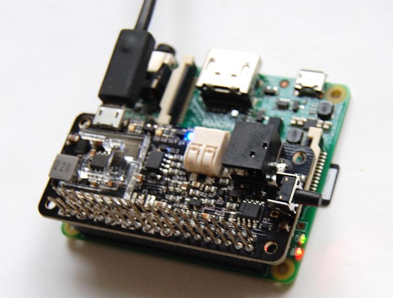
 Blue LED as 5V pass through indicator. 5) Terminal block for power source connection. 6) DC power jack for power source connection. 7) Tact switch for power on/off. 8) 40-pin header footprint.")
5 Product Details The figure below shows how Zero2Go looks like: 1) Micro-USB port for power source connection. 2) Red LED as error indicator. 3) Green LED as DC-DC step down indicator. 4) Blue LED as 5V pass through indicator. 5) Terminal block for power source connection. 6) DC power jack for power source connection. 7) Tact switch for power on/off. 8) 40-pin header footprint. 9) Acrylic protective frame. 3

6 Package Content Each package of Zero2Go contains: Zero2Go board x 1 Plastic male-female standoff x 4 M2.5 x 4 mm screws x 4 M2.5 nuts x 4 Dual-head Pogo pin connector (5-pin set) 4
7 Specifications Dimension: Weight 65mm x 30mm x 9mm 10g (net weight without any accessory) Input Voltage (V in ) 5~26V 1 Output Voltage (V out ) 5V ( 5% tolerance) Max Output Current 2.6A 2 DC-DC Efficiency 88% max Red: lights up when input polarity is reversed LED Indicators Green: lights up when DC-DC converter is working Blue: lights up when input pass through to output Static Current ~0.5mA when V in =5V ~4mA when V in =26V 3 1 Input 5.5~7.0V is not recommended as the DC-DC converter needs more dropout to work well. 2 Without adding heat sink to DC-DC chip and the inductor (U2 and L1), we suggest to keep the current below 1.5A for long term usage. If you are using the Pogo pin connector to output all current to Raspberry Pi Zero and peripherals, the current should be 1A or lower. 3 It is the current drawn from the power source, when Raspberry Pi doesn t get powered. 5
, the first step is")


8 Mounting on Raspberry Pi Zero To mount Zero2Go on Raspberry Pi Zero (without 40-pin header soldered), the first step is to fix the 4 male-female standoffs on four corners with screws. Then you place the pogo pin connector on the correct position. Please make sure the small tip on the plastic frame is on the right and it points to the SD card, as shown below: 6


9 Now you can mount Zero2Go above your Raspberry Pi Zero, please make sure the pogo pin connector contacts the correct pads: Use the 4 nuts to fix your Zero2Go at its place. You may find tweezers are quite helpful in this case: After tightening the 4 nuts, Zero2Go is now firmly mounted on your Raspberry Pi Zero. Please notice the pogo pin connector is designed to work with 1A current, if you are expecting a much higher current output, please consider soldering a 40-pin header for the connection. 7

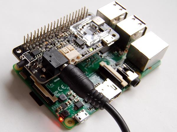
10 Mounting on Other Raspberry Pi Models If you want to mount Zero2Go on other Raspberry Pi models, you will need to solder a 40-pin header (not included in package) on your Zero2Go. Which type of header should you solder? It depends. If you intend to mount Zero2Go on Raspberry Pi A+, B+, 2B or 3B, which has male 40-pin header onboard, you should solder a female 40-pin header on Zero2Go. Optionally it could be a stacking header which has extra long pins. Below is such an example: If you are mounting Zero2Go on a Pi Zero with a female 40-pin header soldered, you should solder a male 40-pin header on your Zero2Go. This is also the suggested way for driving high current devices from Pi Zero. After soldering the pin-header, mounting Zero2Go to your Raspberry Pi is the same with mounting other HATs. Just connect the 40-pin headers together and it is done. The pictures below shows how Zero2Go looks like when being mounted on Raspberry Pi A+ and Raspberry Pi 3. 8
11 9


12 Connect Power Source Zero2Go has three input power port on board, the micro-usb port (A), the terminal block (B) and DC power jack (C). You can use one of them to connect the power source for your Raspberry Pi. Caution: do not connect multiple power sources at the same time! The micro-usb port is for connecting those power adapters with matching plug. The official Raspberry Pi power adapter, many mobile phone chargers and all power banks belongs to this category. Although most devices that output 5V to micro-usb, this micro-usb port can accept 5~26V. The terminal block in white can connect metal wires with diameter 0.5~1mm. When connecting or disconnecting a wire, you need to push the small button on top, and then insert or withdraw the wire. 10


13 The DC power jack in black is for connecting those power adapters with 5.5mm/2.1mm plug. Many power adapters for notebook belongs to this category. Different than the micro-usb and then terminal block, the connection between barrel shaped plug and DC power jack is not that tight, as it could still be rotated after the connection. This might lead to unstable input voltage, which should be avoided. Caution: please avoid poor contact between power source and Zero2Go. If Zero2Go is used on a portable project, it is recommended to use the micro-usb or terminal block for power source connection. If the DC power jack is used, it is recommended to take additional efforts to fix the barrel shaped plug on its place. Please keep in mind that, the power source should have very solid connection to Zero2Go. If you are using the terminal block, please make sure the wires are tightly fixed, and they should not be disconnected during the usage. If the connection is not reliable, it could lead to very bad consequence, especially when input voltage is higher than 20V. In worse case it could burn out the MOSFET on Zero2Go and then kill your Raspberry Pi! Caution: quickly connect and disconnect power source is a big NO NO!!! 11


. In this case the blue LED will light up. If the input voltage is higher than 5.")
14 Working Modes If the input polarity is reversed, the red LED will light up and Zero2Go does not work. This will not harm any device as the power switch is disabled in this case. After correctly connection with the power source, a single tap on the button (K1) will turn on your Raspberry Pi. If the input voltage is less than 5.5V, Zero2Go works in pass-through mode, and the input voltage will be directly output (with very low voltage drop). In this case the blue LED will light up. If the input voltage is higher than 5.5V, Zero2Go works in step-down mode, and the DC-DC converter will convert input voltage to 5V output. In this case the green LED will light up. 12
15 Before Installing Software You will need to installed the OS on the SD card first. We recommend NOT to use NOOBS, instead download the Raspbian image and directly flash it into your SD card (tutorial is here). The process could be faster and you will not have the problem caused by the NOOBS boot menu (read on for details). The software of Zero2Go has been tested under Raspbian Jessie. Raspbian Wheezy should also work, but it is better to use Jessie as it will be much easier to install Qt 5, which is required by the (optional) GUI of the software. The software of Zero2Go might also work on other operating systems with or without modification. The software is written in BASH, so it could be easily modified by the customers to support other OS. However, at lest for now, only Raspbian Jessie and Wheezy are officially tested. You should have mind preparation that tweaking might be needed when using Zero2Go on other operating systems. If you have installed the OS with NOOBS, please make sure to skip the boot menu. Otherwise the boot menu will postpone the booting long enough to make Zero2Go think the system is down and then cut the power (so your Raspberry Pi will not boot). Here is how to skip the NOOBS boot menu: you insert your SD card to your PC (use a SD card reader if your PC doesn t have SD card slot), open the RECOVERY partition and create a text file named autoboot.txt there. Edit it and put this into the file: boot_partition=6 It tells NOOBS to boot from the partition who is numbered 6. It is usually the case when you installed only one OS on the SD card (more details could be found here). If you have multiple OS installed, you can run sudo fdisk l command to find the partition to boot with. Remarks: there is a regression on NOOBS V2.2 and V2.3, so the trick above will not work on (at least) these two versions (details here). We hope it could be fixed soon, meanwhile you can use NOOBS V2.1 to avoid this problem (download from here), or even better, do not use NOOBS and directly flash the OS into the SD card. 13
16 Software Installation After mounting Zero2Go on your Raspberry Pi, you can tap on the button to turn your Raspberry Pi on. However, without installing the software, you can only hold the button for several seconds to force the power cut, which is not recommended. How the Zero2Go software works? The software will run in the background after boot, and listen to your button input (via GPIO-4). It will initiate a shutdown command once you tap on the button. After the system gets shutdown, the TXD pin will go LOW permanently, and Zero2Go will then fully cut the power. Zero2Go s software is a subset of the software for Witty Pi. So if you have installed Witty Pi s software on your Raspberry Pi, you don t need to install Zero2Go s software and it will work just out of the box. To install Zero2Go s software, please run this command in your home directory: pi@raspberrypi ~ $ wget If your Raspberry Pi has internet connection, it will immediately download the script from our website, and you will then see the installzero2go.sh script in your home directory. Then you just need to this script with with sudo: pi@raspberrypi ~ $ sudo sh installzero2go.sh Please notice that sudo is necessary to run this script. This script will copy a file to /etc/init.d/zero2go, and register it to run after boot. 14
17 GPIO Pins Used by Zero2Go Besides the +5V and GND pins, Zero2Go uses GPIO-4 (BCM naming) to monitor the button tapping. The TXD pin is also monitored but it will not affect the data transferring via serial port. Zero2Go will cut power when TXD pin gets pulled down for long enough (> 3 seconds). GPIO (BCM) Name Physical Name GPIO (BCM) 3.3V 1 2 5V 2 SDA V 3 SCL GND 4 GPIO TXD 14 GND 9 10 RXD GPIO GPIO GPIO GND 22 GPIO GPIO V GPIO MOSI GND 9 MISO GPIO SCLK CE0 8 GND CE1 7 0 SDA SCL GPIO GND 6 GPIO GPIO GPIO GND 19 GPIO GPIO GPIO GPIO GND GPIO
 chart to show how the DC-DC converter works.")

18 About the Protective Frame Around the DC-DC chip (U2), there is an Acrylic protective frame, which sticks on the top surface of the PCB with adhesive gel. What is this frame for? It is there to protect the DC-DC circuit, from your finger. Below is a (very simplified) chart to show how the DC-DC converter works. The feedback channel is there to make sure the output voltage is at the expected level. If for any reason, the feedback channel is interfered, the PWM module will collect wrong sample and the output voltage will be wrong. In Zero2Go we use a SO-8 IC (U2) to build the DC-DC converter, some resistors and capacitors around setup the feedback channel for it. If you use a finger to touch some of them at the same time, you may interfere the feedback channel and the result could be disaster (scenario A in figure below). With the Acrylic protective frame mounted, your finger will not be able to touch those components (scenario B in figure below). Caution: please try not to remove the Acrylic protective frame, if you are using Zero2Go without a case. 16
19 Revision History Revision Date Description Initial revision Add caution about unreliable power source connection Add Before Installing Software section Add description of long hold to force power cut behaviour. Fix typo. 17
Zero2Go Omini. Wide Input Range, Multi-Channel Power supply for Raspberry Pi. User Manual (revision 1.01)
") Zero2Go Omini Wide Input Range, Multi-Channel Power supply for Raspberry Pi User Manual (revision 1.01) Copyright 2018 UUGear s.r.o. All rights reserved. Table of Content Product Overview... 1 What is
Zero2Go Omini Wide Input Range, Multi-Channel Power supply for Raspberry Pi User Manual (revision 1.01) Copyright 2018 UUGear s.r.o. All rights reserved. Table of Content Product Overview... 1 What is
Realtime Clock and Power Management for Raspberry Pi
 Witty Pi Mini Realtime Clock and Power Management for Raspberry Pi User Manual (revision 1.01) Copyright 2017 UUGear s.r.o. All rights reserved. Table of Content What is Witty Pi (Mini)?... 1 What is in
[Note: Power adapter is not included in the kits. Users need to prepare a 9 12 V ( >300mA capacity ) DC power supply]
![[Note: Power adapter is not included in the kits. Users need to prepare a 9 12 V ( >300mA capacity ) DC power supply]](/thumbs/76/74094055.jpg "[Note: Power adapter is not included in the kits. Users need to prepare a 9 12 V ( >300mA capacity ) DC power supply]") 062 LCD Oscilloscope Assembly Notes Applicable Models: 06203KP, 06204KP DN062-18v02 Important Notes 1. Some components shown in the schematic and PCB layout are for options or adjustments. They do not
062 LCD Oscilloscope Assembly Notes Applicable Models: 06203KP, 06204KP DN062-18v02 Important Notes 1. Some components shown in the schematic and PCB layout are for options or adjustments. They do not
OpenSprinkler v2.2u Build Instructions
 OpenSprinkler v2.2u Build Instructions (Note: all images below are 'clickable', in order for you to see the full-resolution details. ) Part 0: Parts Check Part 1: Soldering Part 2: Testing Part 3: Enclosure
UPS PIco. for use with. Raspberry Pi B+, A+, B, and A. HAT Compliant. Raspberry Pi is a trademark of the Raspberry Pi Foundation
 UPS PIco Uninterruptible Power Supply with Peripherals and I 2 C control Interface for use with Raspberry Pi B+, A+, B, and A HAT Compliant Raspberry Pi is a trademark of the Raspberry Pi Foundation Gold
Propeller Project Board USB (#32810)
") Web Site: www.parallax.com Forums: forums.parallax.com Sales: sales@parallax.com Technical: support@parallax.com Office: (916) 624-8333 Fax: (916) 624-8003 Sales: (888) 512-1024 Tech Support: (888) 997-8267
Web Site: www.parallax.com Forums: forums.parallax.com Sales: sales@parallax.com Technical: support@parallax.com Office: (916) 624-8333 Fax: (916) 624-8003 Sales: (888) 512-1024 Tech Support: (888) 997-8267
PiJuice Quick Start Guide and FAQ. Getting started. Kit contents
 PiJuice Quick Start Guide and FAQ Getting started As one of the smallest systems around there are so many amazing things you could do with the Raspberry Pi if it was self-powered and portable. Introducing
Setup: Scratch GPIO. What is Scratch? Introducing Scratch GPIO. How to install Scratch GPIO. Obtain Scratch GPIO
 Setup: Scratch GPIO What is Scratch? Scratch is a beginner friendly way to program the Raspberry Pi, designed for those who have not programmed before and are put off by the random keyboard mashing type
Pi PoE Switch HAT Quick Start And FAQ. Getting started. Kit contents
 Pi PoE Switch HAT Quick Start And FAQ Getting started The Pi PoE Switch HAT is an add on board for the Raspberry Pi that brings the Switch technology together with PoE all in one fantastic package! You
Shack Clock kit. U3S Rev 2 PCB 1. Introduction
 Shack Clock kit U3S Rev 2 PCB 1. Introduction Thank you for purchasing the QRP Labs Shack Clock kit. This clock uses the Ultimate3S QRSS/WSPR kit hardware, but a different firmware version. It can be used
Phi-panel backpack assembly and keypad options Dr. John Liu 12/16/2012
 Phi-panel backpack assembly and keypad options Dr. John Liu 12/16/2012 1. Introduction:... 3 Currently available:... 3 2. Backpack assembly... 4 3. Connecting to a keypad... 6 4. Rotary encoder keypads...
Instruction Manual for BE-SP3 Circuit. 10/21/07
 Page 1 of 54 Instruction Manual for BE-SP3 Circuit. 10/21/07 Page 1 Index: Page 2 BE-SP3 Circuit Specifications. Page 3-4 Intro to the BE-SP3. Page 5 Basics of serial to parallel. Page 6-7 ASCII Code.
Preassembled 40-pin Pi Wedge Hookup Guide
 Page 1 of 9 Preassembled 40-pin Pi Wedge Hookup Guide Introduction The preassembled 40-pin Pi Wedge is the newest member in our Pi Wedge family. It s an excellent way to get those pesky Pi pins broken
USB PowerControl 0042-USBPC-DSBT / USBPCNE-DSBT
 Features and Benefits:! The board is a USB to USB solid state relay. It comes in two flavors, one with an Active High Enable line and the other with an Active Low Enable line. The software for this device
Prototyping Module Datasheet
 Prototyping Module Datasheet Part Numbers: MPROTO100 rev 002 Zenseio LLC Updated: September 2016 Table of Contents Table of Contents Functional description PROTOTYPING MODULE OVERVIEW FEATURES BLOCK DIAGRAM
RC Tractor Guy Controller V2.1 Assembly Guide
 RC Tractor Guy Controller V. Assembly Guide Features 0 Push button inputs Dual axis thumb sticks with built-in push button Rotary encoders with built-in push button MCU Socket to suit Meduino Mega 560
Pmod modules are powered by the host via the interface s power and ground pins.
 1300 Henley Court Pullman, WA 99163 509.334.6306 www.store. digilent.com Digilent Pmod Interface Specification 1.2.0 Revised October 5, 2017 1 Introduction The Digilent Pmod interface is used to connect
Parts List: Part # Tools List: Instructions:
 Parts List: Part # 1 pair of Dayton Audio B652s 300-652 1 Dayton Audio DTA-2 amplifier 300-385 1 MP3 module 320-350 1 7805 +5 VDC voltage regulator 7805 1 12 VDC 2A power supply 129-077 1 2.1 mm panel
Application Note: AN0106. On-Board SPI Programming with Dediprog tools: End User Version
 4F., No.7, Ln. 143, Xinming Rd., Neihu Dist., Taipei City 114, Taiwan Application Note: AN0106 On-Board SPI Programming with Dediprog tools: End User Version (This document is provided to help users who
Supplement for module D061 incl. ATMega128 Prozessor
 Supplement for module D061 incl. ATMega128 Prozessor V 1.3 16. March 2006 2006 by Peter Küsters This document is in copyright protected. It is not permitted to change any part of it. It is not permitted
PiRyte Mini ATX PSU Revision User Manual
 Revision 1.1.0 User Manual Overview Congratulations on your purchase of the PiRyte Mini ATX PSU! Please read this entire manual before using to ensure you receive maximum benefit from this board while
Schematic Diagram: R2,R3,R4,R7 are ¼ Watt; R5,R6 are 220 Ohm ½ Watt (or two 470 Ohm ¼ Watt in parallel)
") Nano DDS VFO Rev_2 Assembly Manual Farrukh Zia, K2ZIA, 2016_0130 Featured in ARRL QST March 2016 Issue Nano DDS VFO is a modification of the original VFO design in Arduino Projects for Amateur Radio by
Nano DDS VFO Rev_2 Assembly Manual Farrukh Zia, K2ZIA, 2016_0130 Featured in ARRL QST March 2016 Issue Nano DDS VFO is a modification of the original VFO design in Arduino Projects for Amateur Radio by
PiRyte Mini ATX PSU Revision 1.0 User Manual
 Revision 1.0 User Manual Overview Congratulations on your purchase of the PiRyte Mini ATX PSU! Please read this entire manual before using to ensure you receive maximum benefit from this board while protecting
Arduino Uno. Arduino Uno R3 Front. Arduino Uno R2 Front
 Arduino Uno Arduino Uno R3 Front Arduino Uno R2 Front Arduino Uno SMD Arduino Uno R3 Back Arduino Uno Front Arduino Uno Back Overview The Arduino Uno is a microcontroller board based on the ATmega328 (datasheet).
EZ-Bv4 Datasheet v0.7
 EZ-Bv4 Datasheet v0.7 Table of Contents Introduction... 2 Electrical Characteristics... 3 Regulated and Unregulated Power Pins... 4 Low Battery Warning... 4 Hardware Features Main CPU... 5 Fuse Protection...
BB-303 Manual Baseboard for TMCM-303
 BB-303 Manual Baseboard for TMCM-303 Trinamic Motion Control GmbH & Co. KG Sternstraße 67 D 20357 Hamburg, Germany http://www.trinamic.com BB-303 Manual (V1.04 / Jul 9th, 2007) 2 Contents 1 Features...
PANDORA HACKER GUIDE
 PANDORA HACKER GUIDE WARNING: Modifying your PCB is not covered by your warranty and any damage caused as a result will be the sole responsibility of the owner to fix or to have fixed at a fee set by the
OpenSprinkler v2.1u Build Instructions
 OpenSprinkler v2.1u Build Instructions (Note: all images below are 'clickable', in order for you to see the full-resolution details. ) Part 0: Parts Check Part 1: Soldering Part 2: Testing Part 3: Enclosure
Raspberry Pi board. EB080
 Raspberry Pi board www.matrixmultimedia.com EB080 Contents About this document 3 Board layout 3 General information 4 Circuit description 4 Circuit diagram 5 2 Copyright Matrix Multimedia Ltd. About this
ARDUINO MEGA 2560 REV3 Code: A000067
 ARDUINO MEGA 2560 REV3 Code: A000067 The MEGA 2560 is designed for more complex projects. With 54 digital I/O pins, 16 analog inputs and a larger space for your sketch it is the recommended board for 3D
UPS PIco. for use with. Raspberry Pi B+, A+, B, and A. HAT Compliant. Raspberry Pi is a trademark of the Raspberry Pi Foundation
 UPS PIco Uninterruptible Power Supply with Peripheral and I 2 C control Interface for use with Raspberry Pi B+, A+, B, and A HAT Compliant Raspberry Pi is a trademark of the Raspberry Pi Foundation PiModules
CP5176 Assembly guide. Soldering. CP5176 Assembly guide Main PCB PCB split. Document revision 2.1 Last modification : 12/11/17
 CP5176 Assembly guide Safety warning The kits are main powered and use potentially lethal voltages. Under no circumstance should someone undertake the realisation of a kit unless he has full knowledge
Post Tenebras Lab. Written By: Post Tenebras Lab
 Post Tenebras Lab PTL-ino is an Arduino comptaible board, made entirely out of through-hole components. It is a perfect project to learn how to solder and start getting into the world of micro controllers.
USB-to-I2C. Professional Hardware User s Manual.
 USB-to-I2C Professional Hardware User s Manual https://www.i2ctools.com/ Information provided in this document is solely for use with the USB-to-I2C Professional product from SB Solutions, Inc. SB Solutions,
8051 Intermidiate Development Board. Product Manual. Contents. 1) Overview 2) Features 3) Using the board 4) Troubleshooting and getting help
 Overview 2) Features 3) Using the board 4) Troubleshooting and getting help") 8051 Intermidiate Development Board Product Manual Contents 1) Overview 2) Features 3) Using the board 4) Troubleshooting and getting help 1. Overview 2. Features The board is built on a high quality FR-4(1.6
8051 Intermidiate Development Board Product Manual Contents 1) Overview 2) Features 3) Using the board 4) Troubleshooting and getting help 1. Overview 2. Features The board is built on a high quality FR-4(1.6
1. USB to Serial cable driver installation instructions 2. Instructions for use with Raspberry Pi 3. Instructions for use with WRT54g and similar
 TechnoFix This document contains three sections: 1. USB to Serial cable driver installation instructions 2. Instructions for use with Raspberry Pi 3. Instructions for use with WRT54g and similar Please
Quicksilver 606 TR-606 CPU Upgrade
 Quicksilver 606 TR-606 CPU Upgrade D650C 128 Installation Guide Social Entropy Electronic Music Instruments TABLE OF CONTENTS WARNINGS... 1 OVERVIEW... 2 WHAT'S IN THE BOX... 3 OPENING THE TR-606 CASE...
Manual of ET-LCD SW HAT
 ET- LCD SW HAT ET-LCD SW HAT is Board I/O that is specifically designed for connection with Board Raspberry Pi through Connector 40-PIN; this board includes LCD 16x2, SW, Buzzer, RTC DS3231 with Connector
GPS Series. Build a GPS Smart Logger. By Michael Simpson. As seen in November 2008 of Servo Magazine Pick up an issue at
 GPS Series By Michael Simpson Build a GPS Smart Logger As seen in November 2008 of Servo Magazine Pick up an issue at www.servomagazine.com I recently did a GPS series covering various GPS modules and
Energy Meter and. Current Transducer. Assembly Manual
 Energy Meter and Current Transducer Assembly Manual 2017 1 The energy meter assembly is made of two separate boxes and associated accessories, as follows: Energy Meter (EM) Box, with two cables feeding
UPS PIco HV3.0A. for use with. Raspberry Pi is a trademark of the Raspberry Pi Foundation
 UPS PIco HV3.0A Uninterruptible Power Supply with Peripherals and I 2 C control Interface for use with Raspberry Pi A+, B+, Pi2 B, Pi3 B, Pi Zero HAT Compliant Raspberry Pi is a trademark of the Raspberry
Part 2: Building the Controller Board
 v3.01, June 2018 1 Part 2: Building the Controller Board Congratulations for making it this far! The controller board uses smaller components than the wing boards, which believe it or not, means that everything
Arduino Panel Meter Clock. By Russ Hughes
 Arduino Panel Meter Clock By Russ Hughes (russ@owt.com) OVERVIEW My father has been a lifelong Ham Radio Operator with a fondness for almost anything with a panel meter. After seeing the Trinket Powered
USB-to-I2C. Ultra Hardware User s Manual.
 USB-to-I2C Ultra Hardware User s Manual https://www.i2ctools.com/ Information provided in this document is solely for use with the USB-to-I2C Ultra product from SB Solutions, Inc. SB Solutions, Inc. reserves
M101M4 Tablet PC Quick Start Guide V1.0
 M101M4 Tablet PC Quick Start Guide V1.0 Please read these instructions carefully before using this product, and save this manual for future use. Getting Started Congratulations on purchasing this rugged
Gooligum Electronics 2015
 The Wombat Prototyping Board for Raspberry Pi Operation and Software Guide This prototyping board is intended to make it easy to experiment and try out ideas for building electronic devices that connect
Web Site: Forums: forums.parallax.com Sales: Technical:
 Web Site: www.parallax.com Forums: forums.parallax.com Sales: sales@parallax.com Technical: support@parallax.com Office: (916) 624-8333 Fax: (916) 624-8003 Sales: (888) 512-1024 Tech Support: (888) 997-8267
ARDUINO LEONARDO ETH Code: A000022
 ARDUINO LEONARDO ETH Code: A000022 All the fun of a Leonardo, plus an Ethernet port to extend your project to the IoT world. You can control sensors and actuators via the internet as a client or server.
BuffaloLabs WiFi Lantern Assembly guide version 1
 BuffaloLabs WiFi Lantern Assembly guide version 1 Needed equipment: Solder iron Solder wire Cutter Wire stripper (optional) Hot glue gun Overview of the components (not including USB cable and box panels)
DLA. DMX512 Analyzer. DLA Users Manual SV2_00 B.lwp copyright ELM Video Technology, Inc.
 DLA DMX512 Analyzer DLA DLA-HH 1 Table Of Contents IMPORTANT SAFEGUARDS... 2 DLA OVERVIEW... 3 CONNECTION... 3 OPERATION... 3 HARDWARE SETUP... 4 DLA-HH (PORTABLE) LAYOUT... 4 CHASSIS LAYOUT... 4 DLA MENU
Datasheet BT85x Series Development Kits
 A BT85x Series Development Kits Applicable to the following Laird part numbers: DVK-BT850-SA DVK-BT850-ST Version 1.0 REVISION HISTORY Version Date Notes Contributor Approver 1.0 12 Jan 2018 Initial Release
SM010, Assembly Manual PCB Version 1.0
 180 SM010, Assembly Manual MATRIXARCHATE 16 8 IO SEQUENTIAL MATRIX SIGNAL ROUTER SM010 1 2 1 2 3 4 5 3 4 5 6 7 8 9 10 11 12 6 7 8 9 10 11 12 13 14 15 16 PROGRAM A B C D E F G H f1 f2 20.000 180 SSSR Labs
Micro USB Lamp Kit ESSENTIAL INFORMATION. Version 2.0 DESIGN A STYLISH LAMP WITH THIS
 ESSENTIAL INFORMATION BUILD INSTRUCTIONS CHECKING YOUR PCB & FAULT-FINDING MECHANICAL DETAILS HOW THE KIT WORKS DESIGN A STYLISH LAMP WITH THIS Micro USB Lamp Kit Version 2.0 Build Instructions Before
HOW TO USE ESP8266 WITH ARDUINO IDE
 HOW TO USE ESP8266 WITH ARDUINO IDE This document applies for the following products: ESP8266-EVB; ESP8266-EVB-BAT; ESP8266-EVB-BAT-BOX Document revision B, February 2017 All boards produced by Olimex
Raspberry Pi. Quick-Start Guide. Rev 1.0, Mar 2017
 Raspberry Pi Quick-Start Guide Rev 1.0, Mar 2017 Table of Contents 1. Raspberry Pi Start Kits... 2 A. Generation Introduction:... 2 B. Package including:... 2 2. Assembly... 3 A.16GB Micro SDPre-Loaded
Building the FlipChip Tester
 Building the FlipChip Tester 1. Assembly of the Core Board You will need a fine low-wattage soldering iron and a Voltmeter. Take your time to solder the components on the Core Board. Better to spend a
PARTS LIST 1 x PC Board 36 x 5mm Red LED 36 x 12mm LED Standoff 36 x NPN Transistor 36 x 10kΩ Resistor OTHER PARTS YOU MAY NEED
 PARTS LIST 1 x PC Board 36 x 5mm Red LED 36 x 12mm LED Standoff 36 x NPN Transistor 36 x 150Ω Resistor 36 x 10kΩ Resistor 17 x Mini Toggle on-off 8 x Mini Toggle (on)-off-(on) 1 x 470Ω Resistor 1 x 47µF
USER MANUAL. BBB36+ Beagle Bone Black Cape/ Standalone Lighting Controller
 BBB36+ Beagle Bone Black Cape/ Standalone Lighting Controller USER MANUAL Features -Mates with a BeagleBoneBlack (BBB) running the Falcon Player (previously Falcon Pi Player, FPP) -BBB is powered by the
UF-3701 Power Board Construction Guide
 Page 1/5 Soldering and Part Placement See the Chapter 3 of the MIT 6270 Manual for information on electronic assembly, including soldering techniques and component mounting. Construction Information All
Vector 3D printer complete wire list including extruder PWA listing
 Vector 3D printer complete wire list including extruder PWA listing Conventions Pin numbering for connectors It is normal practice in print circuit board (PCB) layout to denote pin 1 of a PCB mounted connector
ARDUINO MEGA ADK REV3 Code: A000069
 ARDUINO MEGA ADK REV3 Code: A000069 OVERVIEW The Arduino MEGA ADK is a microcontroller board based on the ATmega2560. It has a USB host interface to connect with Android based phones, based on the MAX3421e
Matrix Trident installation tutorial (v1.1) SLIM XBOX360 TUTORIAL
 SLIM XBOX360 TUTORIAL") Matrix Trident installation tutorial (v1.1) SLIM XBOX360 TUTORIAL This tutorial will guide you in the process of installing your Matrix Trident into a Slim or Fat Xbox360 with 16Mb NAND. Once correctly
Matrix Trident installation tutorial (v1.1) SLIM XBOX360 TUTORIAL This tutorial will guide you in the process of installing your Matrix Trident into a Slim or Fat Xbox360 with 16Mb NAND. Once correctly
What is SmartUPS. Connections. Button and LED Indicator. SmartUPS User Guide
 SmartUPS User Guide What is SmartUPS SmartUPS is Uninterruptible Power Supply & Portable Power for Raspberry Pi. SmartUPS runs on 3 AA NiMH rechargeable batteries. Connections 1) Power connection (micro-usb):
RASPBERRY PI MEGA-IO EXPANSION CARD USER'S GUIDE VERSION 2.3
 RASPBERRY PI MEGA-IO EXPANSION CARD www.sequentmicrosystems.com USER'S GUIDE VERSION 2.3 GENERAL DESCRIPTION... 2 BOARD LAYOUT... 3 BLOCK DIAGRAM... 4 COMPONENT DESCRIPTION... 5 CONFIGURATION JUMPERS...
MAIN PCB (The small one)
") THANKS FOR CHOOSING ONE OF OUR KITS! This manual has been written taking into account the common issues that we often find people experience in our workshops. The order in which the components are placed
THANKS FOR CHOOSING ONE OF OUR KITS! This manual has been written taking into account the common issues that we often find people experience in our workshops. The order in which the components are placed
Construction manual. (Almost Ready To Control) Stand , V1.05
 Stand , V1.05") V.3 ARTC Construction manual V.3 ARTC (Almost Ready To Control) Stand 5.08.206, V.05 Qube Solutions UG (limited liability) Arbachtalstr. 6, 72800 Eningen, GERMANY http://www.qube-solutions.de/ http://
V.3 ARTC Construction manual V.3 ARTC (Almost Ready To Control) Stand 5.08.206, V.05 Qube Solutions UG (limited liability) Arbachtalstr. 6, 72800 Eningen, GERMANY http://www.qube-solutions.de/ http://
MP6500 Stepper Motor Driver, Digital Current Control
 This breakout board for the MPS MP6500 micro stepping bipolar stepper motor driver is Pololu s latest stepper motor driver. The module has a pinout and interface that are very similar to that of our popular
Mailbox Notification Service. Created by Adam Kohring
 Mailbox Notification Service Created by Adam Kohring Last updated on 2015-06-24 10:20:07 PM EDT Guide Contents Guide Contents Overview Parts List Adafruit Products Additional Products Print the Circuit
Datasheet BT860 Development Kit
 A BT860 Development Kit Applicable to the following Laird part numbers: - DVK-BT860-SA Integrated antenna version - DVK-BT860-ST Trace pin for external antenna version Version 1.0 REVISION HISTORY Version
MEGATRONICS v3.0 DATASHEET
 MEGATRONICS v3.0 DATASHEET Author Bart Meijer Date 10th of June 2014 Document version 1.2 ReprapWorld.com Megatronics Datasheet Reprapworld.com 1 PRODUCT OVERVIEW Megatronics is based on many famous open-source
970 Serials Lights. Multi-Function Lights System FEATURES SPECIFICATION
 970 Serials Lights Multi-Function Lights System FEATURES Suitable for Marine & Vehicle Easy to install & Easily relearning Remote Unit Wide Range Rotation movement. Dual Function Control with Wire Control
Installing imac Intel 27" EMC 2390 Dual HDD or
 Installing imac Intel 27" EMC 2390 Dual HDD or SSD Drive Installing a secondary HDD or SSD in the mid 2010 27" imac EMC 2390. Written By: Brett Hartt ifixit CC BY-NC-SA www.ifixit.com Page 1 of 23 INTRODUCTION
AVR Intermediate Development Board. Product Manual. Contents. 1) Overview 2) Features 3) Using the board 4) Troubleshooting and getting help
 Overview 2) Features 3) Using the board 4) Troubleshooting and getting help") AVR Intermediate Development Board Product Manual Contents 1) Overview 2) Features 3) Using the board 4) Troubleshooting and getting help 1. Overview 2. Features The board is built on a high quality FR-4(1.6
AVR Intermediate Development Board Product Manual Contents 1) Overview 2) Features 3) Using the board 4) Troubleshooting and getting help 1. Overview 2. Features The board is built on a high quality FR-4(1.6
ARDUINO UNO REV3 SMD Code: A The board everybody gets started with, based on the ATmega328 (SMD).
.") ARDUINO UNO REV3 SMD Code: A000073 The board everybody gets started with, based on the ATmega328 (SMD). The Arduino Uno SMD R3 is a microcontroller board based on the ATmega328. It has 14 digital input/output
ARDUINO UNO REV3 SMD Code: A000073 The board everybody gets started with, based on the ATmega328 (SMD). The Arduino Uno SMD R3 is a microcontroller board based on the ATmega328. It has 14 digital input/output
BMC24. MIDI TO GATE CONVERTER DOCUMENTATION. This documentation is for use with the "Euro Style" bottom board.
 BMC24. MIDI TO GATE CONVERTER DOCUMENTATION. This documentation is for use with the "Euro Style" bottom board. A. USING THE MIDI TO GATE CONVERTER B. PARTS LIST C. BUILDING INSTRUCTIONS D. SCHEMATICS Revision.
Pololu 12V Step-Up/Step-Down Voltage Regulator S10V2F12
 Pololu 12V Step-Up/Step-Down Voltage Regulator S10V2F12 Overview The Pololu step-up/step-down voltage regulator S10V2F12 is a switching regulator (also called a switched-mode power supply (SMPS) or DC-to-DC
PI36 Raspberry PI Cape/ Standalone Lighting Controller USER MANUAL
 PI36 Raspberry PI Cape/ Standalone Lighting Controller USER MANUAL Features -Mates with a Raspberry Pi running the Falcon Player (previously Falcon Pi Player, FPP) -PI is powered by the onboard regulator.
UPS PIco HV3.0B+ HAT Stack/Top-End
 UPS PIco HV3.0B+ HAT Stack/Top-End Intelligent Mobile Power Bank and Uninterruptible Power Supply with RTC, Peripherals and I 2 C control Interface Especially Designed for the New Raspberry Pi 3 Model
MINITRONICS v1.0 DATASHEET
 MINITRONICS v. DATASHEET Author Bart Meijer Date 2th of April 23 Document version. ReprapWorld.com PRODUCT OVERVIEW Minitronics is the latest development of ReprapWorld.com. It's designed to be an easy
Win-I2CUSB Hardware User s Manual
 Win-I2CUSB Hardware User s Manual http://www.demoboard.com Information provided in this document is solely for use with the Win-I2CUSB product from The Boardshop. The Boardshop and SB Solutions, Inc. reserve
Arduino ADK Rev.3 Board A000069
 Arduino ADK Rev.3 Board A000069 Overview The Arduino ADK is a microcontroller board based on the ATmega2560 (datasheet). It has a USB host interface to connect with Android based phones, based on the MAX3421e
Arduino Dock 2. The Hardware
 Arduino Dock 2 The Arduino Dock 2 is our supercharged version of an Arduino Uno R3 board. These two boards share the same microcontroller, the ATmel ATmega328P microcontroller (MCU), and have identical
Raspberry-Pi Shield: Binary-Coded-Decimal Clock
 Raspberry-Pi Shield: Binary-Coded-Decimal Clock ASSEMBLY INSTRUCTIONS What is it? This kit builds a binary-coded-decimal clock, driven by a Raspberry-Pi (which should be mounted on the back). This is a
ARDUINO UNO REV3 Code: A000066
 ARDUINO UNO REV3 Code: A000066 The UNO is the best board to get started with electronics and coding. If this is your first experience tinkering with the platform, the UNO is the most robust board you can
Teensy 3.5/3.6 Breakout (Revision A, Standard)
") Teensy 3.5/3.6 Breakout (Revision A, Standard) This is a breakout for the Teensy 3.5 and Teensy 3.6 development boards by PJRC. Included are all the pin headers you need to assemble it, a switch to select
Teensy 3.5/3.6 Breakout (Revision A, Standard) This is a breakout for the Teensy 3.5 and Teensy 3.6 development boards by PJRC. Included are all the pin headers you need to assemble it, a switch to select
RaspiDigiHamClock. Raspberry Pi Amateur Radio Digital Clock. v WA4EFH R.Grokett
 RaspiDigiHamClock Raspberry Pi Amateur Radio Digital Clock v2018-07-08 WA4EFH R.Grokett Overview Amateur Radio Operators (aka HAM Radio) use 24 hour UTC (Universal Coordinated Time) for much of their operation.
THINKPAD X220/X230 FHD MOD
 THINKPAD X220/X230 FHD MOD Overview and installation guide by nitrocaster / Pavel Kovalenko Document version: 0.2 Jun. 13, 2018 Hardware revision: 5 1 RECORD OF REVISIONS Revision
The basic product comes with the IRS5 control board, 3 internal cables, 1 external cable with a 5 volt adapter and a mounting bracket with hardware.
 Please read these instructions and watch the Installation Video before you proceed with the installation of the PC-IRS5-01. Installation Video: http://youtu.be/os98e32vhb4 The PC-IRS5-01 Infrared Receiver
Installation/assembly manual for DCC/Power shield
 Installation/assembly manual for DCC/Power shield The DCC circuit consists of the following components: R1/R6 R2/R3 R4/R5 D1 C2 2 kω resistor ½ Watt (colour code Red/Black/Black/Brown/Brown) 10 kω resistor
The Information contained herein is subject to change without notice. Revisions may be issued regarding changes and/or additions.
 Garret 50C TM Gumstix, Inc. shall have no liability of any kind, express or implied, arising out of the use of the Information in this document, including direct, indirect, special or consequential damages.
AXE Stack 18. BASIC-Programmable Microcontroller Kit. An inexpensive introduction to microcontroller technology for all ability levels
 Ltd AXE Stack 18 BASIC-Programmable Microcontroller Kit a division of An inexpensive introduction to microcontroller technology for all ability levels Free Windows interface software Programmable in BASIC
BehringerMods.com. Instructions for modification of Behringer SRC analog inputs and outputs
 BehringerMods.com Instructions for modification of Behringer SRC analog inputs and outputs The following instructions will cover the details of fully modifying a unit with analog output and analog input
Upgrading a 2U CHP to an i7 Quad Core SBC
 Upgrading a 2U CHP to an i7 Quad Core SBC 1. Parts required: i7 SBC Slim line SATA DVD drive Combined SATA data and power cable for slim-line optical drive Serial port ribbon cable - 9way D male to 10
A Beginners Guide to Raspberry Pi
 A Beginners Guide to Raspberry Pi WHAT IS THE RASPBERRY PI? Features It is a low-cost, credit-card sized computer developed in the UK by the Raspberry Pi Foundation. It has been designed with education
Keysight Technologies How to build a fixture for use with the Keysight Cover-Extend Technology. Application Note
 Keysight Technologies How to build a fixture for use with the Keysight Cover-Extend Technology Application Note Introduction Cover-Extend Technology (CET) is Keysight s latest limited access solution for
Device: PLT This document Version: 3.0. For hardware Version: 4. For firmware Version: Date: April 2014
 Device: PLT-1001 This document Version: 3.0 For hardware Version: 4 For firmware Version: 2.10 Date: April 2014 Description: LED Matrix Display Driver board PLT-1001v4 datasheet Page 2 Contents Introduction...
USBCNC USB Disk Key reader for CNC Controls Machine Mount instructions
 USBCNC USB Disk Key reader for CNC Controls Machine Mount instructions 2008-2015 Calmotion LLC, All rights reserved Calmotion LLC 21720 Marilla St. Chatsworth, CA 91311 www.calmotion.com Introduction This
PCB-STM32-F3U. Development baseboard for the STMicro Discovery-F3 module (STMicro part# STM32F3DISCOVERY)
") PCB-STM32-F3U Development baseboard for the STMicro Discovery-F3 module (STMicro part# STM32F3DISCOVERY) Part Number: PCB-STM32-F3U (unpopulated PCB with Discovery module sockets, no other parts) STM32-F3U
PCB-STM32-F3U Development baseboard for the STMicro Discovery-F3 module (STMicro part# STM32F3DISCOVERY) Part Number: PCB-STM32-F3U (unpopulated PCB with Discovery module sockets, no other parts) STM32-F3U
Adafruit PowerBoost Charger
 Adafruit PowerBoost 500 + Charger Created by lady ada Last updated on 2015-10-21 12:44:24 PM EDT Guide Contents Guide Contents Overview Pinouts Power Pins Control Pins LEDs Battery and USB connection On/Off
SMK525 / SMK585 / SMK595
 SMK525 / SMK585 / SMK595 RACK MOUNTABLE 1 / 8 / 16 PORT PS2 KVM SWITCH USER S MANUAL Rev 1.2 TABLE OF CONTENTS INTRODUCTION...1 FEATURES....1 PACKAGE CONTENTS..... 2 TECHNICAL SPECIFICATIONS...3 SYSTEM