Programmable Logic Controllers Basic Level
|
|
|
- Colleen Morgan
- 6 years ago
- Views:
Transcription

1 Programmable Logic Controllers Basic Level Workbook TP 301 With CD-ROM Festo Didactic en
2 2 Authorised applications and liability The Learning System for Automation and Technology has been developed and prepared exclusively for training in the field of automation. The training organization and / or trainee shall ensure that the safety precautions described in the accompanying Technical documentation are fully observed. Festo Didactic hereby excludes any liability for injury to trainees, to the training organization and / or to third parties occurring as a result of the use or application of the station outside of a pure training situation, unless caused by premeditation or gross negligence on the part of Festo Didactic. Order No.: Edition: 08/2002 Authors: Eckhard von Terzi, Christine Löffler, Frank Ebel Graphics: Doris Schwarzenberger Layout: Beatrice Huber Festo Didactic SE, Rechbergstraße 3, Denkendorf, Germany, 2015 All rights reserved did@de.festo.com The purchaser shall receive a single right of use which is non-exclusive, nontime-limited and limited geographically to use at the purchaser's site/location as follows. The purchaser shall be entitled to use the work to train his/her staff at the purchaser's site/location and shall also be entitled to use parts of the copyright material as the basis for the production of his/her own training documentation for the training of his/her staff at the purchaser's site/location with acknowledgement of source and to make copies for this purpose. In the case of schools/technical colleges and training centres, the right of use shall also include use by school and college students and trainees at the purchaser's site/location for teaching purposes. The right of use shall in all cases exclude the right to publish the copyright material or to make this available for use on intranet, Internet and LMS platforms and databases such as Moodle, which allow access by a wide variety of users, including those outside of the purchaser's site/location. Entitlement to other rights relating to reproductions, copies, adaptations, translations, microfilming and transfer to and storage and processing in electronic systems, no matter whether in whole or in part, shall require the prior consent of Festo Didactic.
3 3 Preface The Festo Didactic Learning System for Automation and Technology is designed to meet a number of different training and vocational requirements, and the training packages are structured accordingly: Basic packages convey basic knowledge spanning a wide range of technologies Technology packages deal with important areas of open and closedloop control technology Function packages explain the basic functions of automated systems Application packages provide basic and further training closely oriented to everyday industrial practice The technology packages encompass pneumatics, electro-pneumatics, control pneumatics, programmable logic controllers, hydraulics, electrohydraulics, proportional hydraulics and control hydraulics. Mounting Frame Fig. 1: Pneumatics i.e. mobile workstation Profile Plate U = 230 V~ p = 6 MPa Storage tray
4 4 The modular design of the learning system permits applications beyond the limits of the individual packages. PLC actuation, for example, is therefore possible of pneumatic, hydraulic and electrical actuators. All learning packages have an identical structure: Hardware Teachware Software Courses The hardware consists of industrial components and installations adapted for didactic purposes. The courseware is matched methodologically and didactically to the training hardware. The courseware comprises: Textbooks (with exercises and examples) Workbooks (with practical exercises, worksheets, supplementary notes, solutions and data sheets) Overhead transparencies and videos (as a visual means of teaching support) The teaching and learning media are available in several languages. They have been designed for use in classroom teaching, but can also be used for self-study purposes. In the software field, computer-based training programs, computer simulating programs, CAD programs and programming software for programmable logic controllers are available. Festo s Didactic range of products for basic and further training is completed by a comprehensive selection of courses matched to the contents of the technology packages.
5 5 Table of contents Technology package TP Layout of this workbook 14 Component/exercise table 15 Equipment set TP Notes on safety 17 Operating notes 18 Section A Course Components of a programmable logic controller Exercise 1: Design and commissioning of a programmable logic controller Components of a PLC A-3 Programming to EN (IEC 61131) Exercise 2: From problem to solution taking into consideration EN (IEC 61131) Practical steps for PLC programming A-11 Basic logic operations Exercise 3: Exercise 4: Exercise 5: Exercise 6: Lamp circuit The assignment function A-19 Burglar alarm The NOT function A-29 Press with protective guard The AND function A-39 Bell system The OR function A-49
6 6 Logic control systems without latching properties Exercise 7: Exercise 8: Stamping device Combination of AND/OR/NOT A-59 Silo control system for two bulk materials Combination circuit with branching A-69 Logic control systems with latching properties Exercise 9: Exercise 10: Exercise 11: Fire alarm Setting an output A-77 Drill breakage monitoring Setting and resetting an output A-85 Activating a cylinder Signal edges A-95 Logic control systems with time response Exercise 12: Exercise 13: Exercise 14: Bonding of components Pulse A-107 Embossing device Switch-on signal delay A-117 Clamping device Switch-off signal delay A-127 Sequence control systems Exercise 15: Exercise 16: Exercise 17: Lifting device for packages Linear sequence A-137 Lifting and sorting device for packages Alternative branching A-155 Stamping device with counter Counting cycles A-167
7 7 Section B Fundamentals Chapter 1 Automating with a PLC B Introduction B Areas of application of a PLC B Basic design of a PLC B The new PLC standard EN (IEC 61131) B-8 Chapter 2 Fundamentals B The decimal number system B The binary number system B The BCD code B The hexadecimal number system B Signed binary numbers B Real numbers B Generation of binary and digital signals B-15 Chapter 3 Boolean operations B Basic logic functions B Further logic operations B Establishing switching functions B Simplification of logic functions B Karnaugh-Veitch diagram B-30
8 8 Chapter 4 Design and mode of operation of a PLC B Structure of a PLC B Central control unit of a PLC B Function mode of a PLC B Application program memory B Input module B Output module B Programming device/personal computer B-45 Chapter 5 Programming of a PLC B Systematic solution finding B EN (IEC ) structuring resources B Programming languages B-54 Chapter 6 Common elements of programming languages B Resources of a PLC B Variables and data types B Program B-70 Chapter 7 Function block diagram B Elements of function block diagram B Evaluation of networks B Loop structures B-87 Chapter 8 Ladder diagram B Elements of ladder diagram B Functions and function blocks B Evaluation of current rungs B-93
9 9 Chapter 9 Instruction list B Instructions B Operators B Functions and function blocks B-97 Chapter 10 Structured text B Expressions B Statements B Selection statements B Iteration statements B-106 Chapter 11 Sequential function chart B Introduction B Elements of sequential function chart B Transitions B Steps B Example B-135 Chapter 12 Logic control systems B What is a logic control system B Logic control systems without latching properties B Logic control systems with memory function B Edge evaluation B-148 Chapter 13 Timers B Introduction B Pulse timer B Switch-on signal delay B Switch-off signal delay B-158
10 10 Chapter 14 Counter B Counter functions B Incremental counter B Decremental counter B Incremental/decremental counter B-167 Chapter 15 Sequence control systems B What is a sequence control system B Function chart to IEC B-169 Chapter 16 Commissioning and operational safety of a PLC B Commissioning B Operational safety of a PLC B-177 Chapter 17 Communication B The need for communication B Data transmission B Interfaces B Communication in the field area B-185 Appendix A Bibliography of illustrations B-187 B Bibliography of literature B-189 C Guidelines and standards B-191 D Glossary B-193 E Index B-199
11 11 Section C Solutions Solution 1: Design and commissioning of a programmable logic controller C-3 Solution 2: Practical steps for PLC programming C-5 Solution 3: Lamp circuit C-7 Solution 4: Burglar alarm C-11 Solution 5: Press with protective guard C-15 Solution 6: Bell system C-21 Solution 7: Stamping device C-25 Solution 8: Silo control system for two bulk materials C-31 Solution 9: Fire alarm C-35 Solution 10: Drill breakage monitoring C-39 Solution 11: Activating a cylinder C-43 Solution 12: Bonding of components C-47 Solution 13: Embossing device C-53 Solution 14: Clamping device C-57 Solution 15: Lifting device for packages C-63 Solution 16: Lifting and sorting device for packages C-69 Solution 17: Stamping device with counter C-75
12 12
13 13 Technology package TP301 Programmable logic controllers The technology package TP301 "Programmable logic controllers" is a component part of the Festo Didactic Learning System for Automation and Technology and forms the basic level of TP300. The training aims of TP301 are to learn how to program programmable logic controllers and to teach the fundamentals for creating programs in the programming languages ladder diagram (LD), function block diagram (FBD), instruction list (IL), structured text (ST) and sequential function chart (SFC). Programming is effected in accordance with EN (IEC ). You have the option of using this workbook in conjunction with alternative programmable logic controllers by different manufacturers. A basic knowledge of electro-pneumatics and sensor technology is recommended to work through technology package TP301. The exercises in TP301 deal with the following main topics: Components of a programmable logic controller PLC programming to EN (IEC 61131) Basic logic operations Logic control systems Sequence control systems The allocation of components and exercises can be seen from the component/exercise table.
14 14 Layout of this workbook The workbook is structured as follows: Section A Course Section B Fundamentals Section C Solutions Section D Appendix Section A Course teaches the programming of programmable logic controllers with the help of a series of progressive exercises. Any necessary technical knowledge required for the implementation of an exercise is provided at the beginning. Functions are limited to the most elementary requirements. More detailed knowledge may be gained in section B. Section C Solutions provides the solutions to the exercises with brief explanations. Section B Fundamentals contains generally applicable technical knowledge to supplement the training contents of the exercises in Section A. Theoretical links are established and the necessary technical terminology explained with the help of examples. An index provides an easy means of locating terminology. Section D Appendix which contains data sheets of the used components.
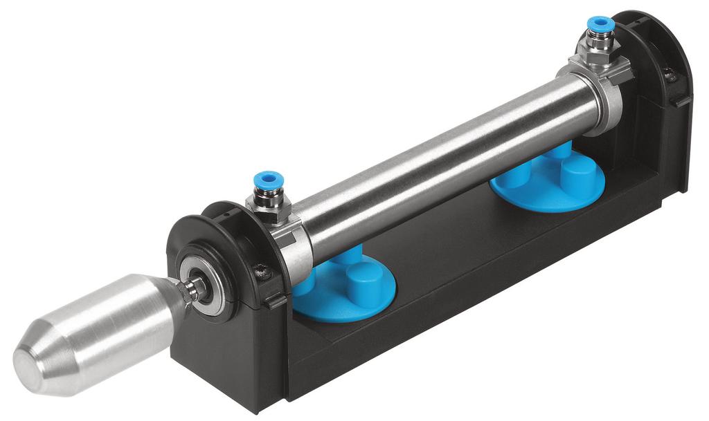
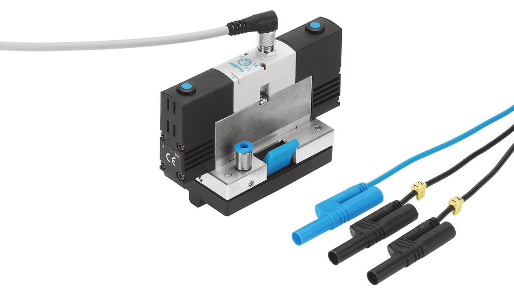
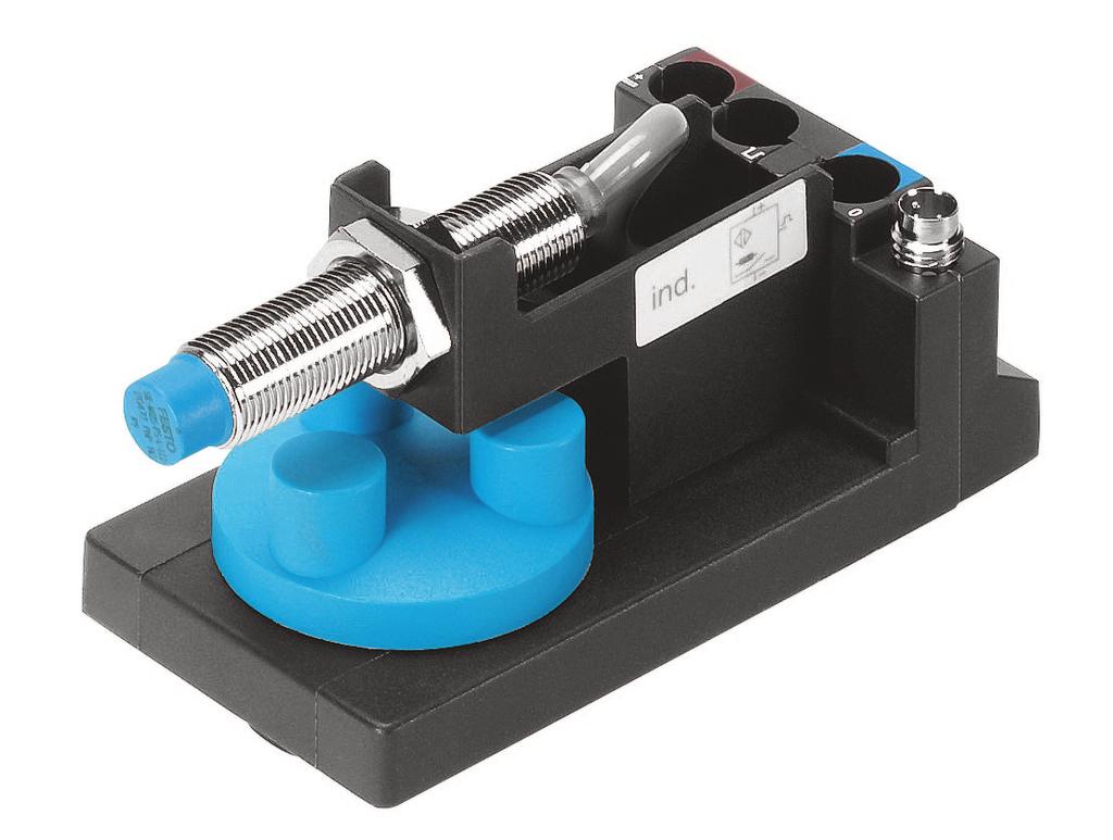
15 15 Allocation of component and exercise Description Signal input, electrical Signalling device and distributor, electrical Proximity sensor, optical Proximity sensor, inductive Proximity sensor, capacitive Proximity sensor with cylinder mounting /2-way single solenoid valve /2-way double solenoid valve Double-acting cylinder Single-acting cylinder On/off valve with filter regulator valve Manifold
16 16 Equipment set TP301 Equipment set TP301 Order No.: Description Order No. Quantity Plastic tubing Manifold Single-acting cylinder Double-acting cylinder On/off valve with filter regulator valve Quick push-pull distributor Signal input, electrical Signalling device and distributor, electrical Proximity sensor with cylinder mounting /2-way single solenoid valve /2-way double solenoid valve Proximity sensor, inductive Proximity sensor, capacitive Proximity sensor, optical optional, not included in scope of delivery of equipment set Order No. Quantity I/O data cable, digital Plug-in adapter Universal connection unit Power supply unit Set of cables
17 17 Notes on safety The following notes should be followed in the interest of safety: Mount all components securely on the board. Do not switch on compressed air until all line connections have been established and secured. Proceed with care when switching on the compressed air. Cylinders may advance or retract as soon as the compressed air is switched on. Switch off air supply immediately if air lines become detached. This prevents accidents. Do not disconnect air lines under pressure. Do not exceed the permitted working pressure of 8 bar (800kPa). Observe general safety regulations in accordance with EN (IEC ). Use only extra-low voltages of up to 24 V DC. Observe the data sheets referring to the individual components, in particular all notes regarding safety.
18 18 Operating notes The following rules should be observed when constructing a circuit: Block output 2 of the valve, if a single-acting cylinder is actuated by a 5/2-way single solenoid valve in a circuit. Fig. 2: Plug for output 2 of a 5/2-way valve Input signals, which would result from an actual production process sequence, are reproduced in part by signals via push buttons or switches.
19 A-1 Section A Course Components of a programmable logic controller Exercise 1: Design and commissioning of a programmable logic controller Components of a PLC A-3 Programming to EN (IEC 61131) Exercise 2: From problem to solution taking into consideration EN (IEC 61131) Practical steps for PLC programming A-11 Basic logic operations Exercise 3: Exercise 4: Exercise 5: Exercise 6: Lamp circuit The assignment function A-19 Burglar alarm The NOT function A-29 Press with protective guard The AND function A-39 Bell system The OR function A-49 Logic control systems without latching properties Exercise 7: Exercise 8: Stamping device Combination of AND/OR/NOT A-59 Silo control system for two bulk materials Combination circuit with branching A-69
20 A-2 Logic control systems with latching properties Exercise 9: Exercise 10: Exercise 11: Fire alarm Setting an output A-77 Drill breakage monitoring Setting and resetting an output A-85 Activating a cylinder Signal edges A-95 Logic control systems with time response Exercise 12: Exercise 13: Exercise 14: Bonding of components Pulse A-107 Embossing device Switch-on signal delay A-117 Clamping device Switch-off signal delay A-127 Sequence control systems Exercise 15: Exercise 16: Exercise 17: Lifting device for packages Linear sequence A-137 Lifting and sorting device for packages Alternative branching A-155 Stamping device with counter Counting cycles A-167
21 A-3 Exercise 1 Programmable logic controllers Design and commissioning of a programmable logic controller Components of a PLC To be able to explain the basic design and mode of operation of a PLC To be able to configure and commission a PLC Nowadays, programmable logic controllers form part of any automation process. Fig. A1.1 illustrates the typical configuration of an automation solution realised by means of a PLC. The control system shown represents the simpler, non-networked group of PLC applications. Subject Title Training aim Technical knowledge PC / Programming device Display/ Control unit Fig. A1.1: Automation via PLC PLC Sensors Actuators
22 A-4 Exercise 1 The basic components of the control system are: Programmable logic controller (PLC) By this, we understand the electronic modules through which all of the system or machine functions to be controlled are addressed and activated in a logic sequence. Sensors These components are located directly on the system or machinery be controlled, through to which the PLC is communicated actual statuses. Actuators These components are located directly on the system or machinery to be controlled, through which the PLC is able to change or influence statuses and as such the technical process. PC or programming device This is used to create the program containing the logic of the system or machinery to be controlled and to transfer this to the memory of the PLC. At the same time, these programming tools also provide supporting functions for the testing of the PLC program and commissioning of the controller. Display and control units These enables you to monitor and influence the operation of the system or machinery. Programmable logic controller The most important component of a control system is the PLC and its program. Fig. A1.2 illustrates the system components of a PLC. Fig. A1.2: System components of a PLC PLC-program Input module Central control unit Output module Sensors Actuators
23 A-5 Exercise 1 A PLC is connected to the system to be controlled via input and output modules. The system to be controlled supplies input signals (mostly binary) via sensors to the input modules. These signals are processed within the main processing unit, the main component of the PLC. Prior.to formulation of IEC standards, known as "central control unit" (CCU). The "specification" for the processing of signals is defined in the PLC program. The result of the processing is output to the actuators of the system to be controlled via the output module. Thus, the design of a PLC corresponds to that of a computer. PLC program PLC programs consist of a logic sequence of instructions. The control program is stored in a special, electronic readable memory, the socalled program memory of the PLC. Special RAMs with back-up battery are used during the program development, since its contents can always be changed again very quickly. After commissioning and error-free function of the controller it is a good idea to transfer the PLC program unerasably to a read-only memory, e.g. an EPROM. If the program is executed, it will be processed in continuous cycles. Signals Input signals reach the PLC via sensors. These signals contain information about the status of the system to be controlled. It is possible to input binary, digital and analogue signals. A PLC can only recognise and output electrical signals. For this reason, non-electrical signals are converted into electrical signals by the sensors. Sensor examples are: Push buttons, switches, limit switches, proximity sensors Output signals influence the system to be controlled. The signals can be output in the form of binary, digital or analogue signals. Output signals are amplified into switching signals via the actuators or converted into signals of other energy forms. Actuators examples are: Lamps, buzzers, bells, contactors, cylinders with solenoid valves, stepper motors
24 A-6 Exercise 1 Problem description A control task is to be solved via a programmable logic controller (PLC). Familiarise yourself with the basic design of a PLC. Positional sketch Exercise definition 1. Components of a PLC 2. Design and commissioning of the PLC you have selected Implementation To carry out the exercise using the worksheets, refer to Section B of the workbook and your PLC data sheet or manual.
25 A-7 Exercise 1 WORKSHEET 1.1 Components of a PLC Question 1: What are the basic components of a programmable logic controller? Question 2: What are the basic modules making up the central control unit of a programmable logic controller?
26 A-8 Exercise 1 Question 3: How is electrical isolation achieved between sensor/actuator signals and the PLC?
27 A-9 Exercise 1 WORKSHEET 1.2 Design and commissioning of the PLC you have selected Enter the technical data of the selected programmable logic controller in the table below. Criteria Operating voltage Nominal voltage Permissible voltage range Current consumption Inputs Number Input current Input level Outputs Number Switching logic Output voltage Output current Technical data Technical data Configure the PLC in accordance with the notes in the relevant data sheet or manual.
28 A-10 Exercise 1
29 C-1 Solutions Section C Solutions Components of a programmable logic controller Solution 1: Design and commissioning of a programmable logic controller Components of a PLC C-3 Programming to EN (IEC 61131) Solution 2: From problem to solution taking into consideration EN (IEC 61131) Practical steps for PLC programming C-5 Basic logic operations Solution 3: Solution 4: Solution 5: Solution 6: Lamp circuit The assignment function C-7 Burglar alarm The NOT function C-11 Press with protective guard The AND function C-15 Bell system The OR function C-21 Logic control systems without latching properties Solution 7: Solution 8: Stamping device Combination of AND/OR/NOT C-25 Silo control system for two bulk materials Combination circuit with branching C-31
30 C-2 Solutions Logic control systems with latching properties Solution 9: Solution 10: Solution 11: Fire alarm Setting an output C-35 Drill breakage monitoring Setting and resetting an output C-39 Activating a cylinder Signal edges C-43 Logic control systems with time response Solution 12: Solution 13: Solution 14: Bonding of components Pulse C-47 Embossing device Switch-on signal delay C-53 Clamping device Switch-off signal delay C-57 Sequence control systems Solution 15: Solution 16: Solution 17: Lifting device for packages Linear sequence C-63 Lifting and sorting device for packages Alternative branching C-69 Stamping device with counter Counting cycles C-75
31 C-3 Solution 1 Design and commissioning of a programmable logic controller Components of a PLC Title Components of a PLC What are the basic components of a programmable logic controller? The basic components of a PLC are: the main processing unit, formerly (central control unit) the input modules the output modules the program memory the PLC program Question 1 Answer What are the basic modules making up the main processing unit of a programmable logic controller? The basic modules of an MPU are: the control unit the data memory the arithmetic and logic unit (ALU) Question 2 Answer How is electrical isolation achieved between sensor/actuator signals and the PLC? The sensor/actuator signals and the PLC are electrically isolated via an optocoupler. The main processing unit is thus separated from the external circuit of the sensors and actuators. Interferences in these circuits therefore cannot damage the controller. Question 3 Answer Inputsignal Error voltage detection Signal delay Optocoupler Signal to the control unit Block diagram of an input module
32 C-4 Solution Design and commissioning of your selected PLC The following table lists the technical data of a Festo FPC 101B programmable logic controller as an example. Technical data Criteria Operating voltage Technical data Nominal voltage Permissable voltage range Current consumption 24 V DC 16 to 30 VDC approx. 160 ma Inputs Number 21 of which 1 is a counter input Input voltage Input level 6 ma log. 0 = 0 to 5 V log. 1 = 11 to 30 V Outputs Number Type Output voltage Output current 14 Transistor outputs positive switching Operating voltage 2 V max. 300 ma/output Total output current max. 2.5 A
Fundamentals of circuits with contacts
 Fundamentals of circuits with contacts Workbook TP 1211 With CD-ROM 24 V F1 1 2 1 2 3 4 5 6 7 21 F2 22 21 S2 22 S1 13 21 43 Q1 43 Q2 S3 14 13 Q1 21 14 22 13 44 Q2 13 14 15 K1 K1 44 25 22 14 16 28 21 21
Electropneumatics Basic Level Textbook TP 201
 Electropneumatics Basic Level Textbook TP 201 Festo Didactic 091181 en Order No.: 091181 Edition: 07/2004 Author: F. Ebel, G. Prede, D. Scholz Graphics: Doris Schwarzenberger Layout: 19.07.04, Susanne
Basic principles of digital technology
 Basic principles of digital technology Workbook TP With CD-ROM S S & B & B = & B S S B B B Festo Didactic 8 en Order no. 8 Edition: / Author: Stefan Enderle Editor: Frank Ebel Graphics: Susanne Durz, Stefan
PLC Applications Electromechanical Systems Using DC Motors
 Mechatronics PLC Applications Electromechanical Systems Using DC Motors Job Sheets - Courseware Sample 85251-F0 Order no.: 85251-30 First Edition Revision level: 04/2015 By the staff of Festo Didactic
Pneumatics Simulation Software (LVSIM - PNEU) - 10 Users
 - 10 Users") Pneumatics Simulation Software (LVSIM - PNEU) - 10 Users LabVolt Series Datasheet Festo Didactic en 07/2018 Table of Contents General Description 2 Features 2 Equipment Box Items 3 Computer Requirements
Pneumatics Simulation Software (LVSIM - PNEU) - 10 Users LabVolt Series Datasheet Festo Didactic en 07/2018 Table of Contents General Description 2 Features 2 Equipment Box Items 3 Computer Requirements
Electro-Pneumatic Training System
 8075-20 Electro-Pneumatic Training System LabVolt Series Datasheet Festo Didactic en 01/2018 Table of Contents General Description 2 PLC Compatibility 2 Features & Benefits 2 List of Equipment 2 List of
6485-V0 Pneumatics Simulation Software (LVSIM -PNEU) - 35 Users Network
 - 35 Users Network") 6485-V0 Pneumatics Simulation Software (LVSIM -PNEU) - 35 Users Network LabVolt Series Datasheet Festo Didactic en 12/2017 Table of Contents General Description 2 Features 3 Equipment Box Items 4 Computer
6485-V0 Pneumatics Simulation Software (LVSIM -PNEU) - 35 Users Network LabVolt Series Datasheet Festo Didactic en 12/2017 Table of Contents General Description 2 Features 3 Equipment Box Items 4 Computer
EDEXCEL NATIONAL CERTIFICATE/DIPLOMA SELECTION AND APPLICATIONS OF PROGRAMMABLE LOGIC CONTROLLERS UNIT 25 - NQF LEVEL 3 OUTCOME 2 - PROGRAMMING
 EDEXCEL NATIONAL CERTIFICATE/DIPLOMA SELECTION AND APPLICATIONS OF PROGRAMMABLE LOGIC CONTROLLERS UNIT 25 - NQF LEVEL 3 OUTCOME 2 - PROGRAMMING CONTENT Be able to use programming techniques to produce
Conveyor Station Exercise 1: Learning about components and their function
 Conveyor Station Exercise 1: Learning about components and their function Learning objective Upon completing this exercise, you should be familiar with the most important components in the conveyor station
NPTEL
 NPTEL Syllabus Automation & Sensor Interface Laboratory - Web course COURSE OUTLINE Automation & Sensor interface laboratory is an application oriented course with review of automation principles, followed
Advanced PLC Training System (Rockwell Automation)
") 3355-00 Advanced PLC Training System (Rockwell Automation) LabVolt Series Datasheet Festo Didactic en 03/208 Table of Contents General Description 2 PLC applications developing students understanding 3
3355-00 Advanced PLC Training System (Rockwell Automation) LabVolt Series Datasheet Festo Didactic en 03/208 Table of Contents General Description 2 PLC applications developing students understanding 3
Mechatronics Programmable Logic Controller Basic Programming Courseware Sample
 Mechatronics Programmable Logic Controller Basic Programming Courseware Sample 52281-F0 Order no.: 52281-10 First Edition Revision level: 08/2015 By the staff of Festo Didactic Festo Didactic Ltée/Ltd,
Project Planning. Module 4: Practice Exercises. Academic Services Unit PREPARED BY. August 2012
 Project Planning PREPARED BY Academic Services Unit August 2012 Applied Technology High Schools, 2012 Module Objectives Upon successful completion of this module, students should be able to: 1. Select
Scientech Universal PLC Platform. Features. New
 New In today's environment of automation, the importance of PLC has rapidly increased. Universal PLC Platform is an ideal setup to study the working of PLC's used for industrial applications. has been
Advanced PLC Training System (Siemens) (3355-A0)
 (3355-A0)") Advanced PLC Training System (Siemens) 595849 (3355-A0) LabVolt Series Datasheet Festo Didactic en 0 V - 0 Hz 04/2019 Table of Contents General Description 2 PLC applications developing students understanding
Advanced PLC Training System (Siemens) 595849 (3355-A0) LabVolt Series Datasheet Festo Didactic en 0 V - 0 Hz 04/2019 Table of Contents General Description 2 PLC applications developing students understanding
PLC Fundamentals. Module 2: Hardware and Terminology. Academic Services Unit PREPARED BY. August 2011
 PLC Fundamentals Module 2: Hardware and Terminology PREPARED BY Academic Services Unit August 2011 Applied Technology High Schools, 2011 ATE1212 PLC Fundamentals Module 2: Hardware and Terminology Module
Fundamentals of direct current technology
 Fundamentals of direct current technology Workbook With CD-ROM P 24 U L 6 mw V U L 16 12 4 3 P 8 2 4 1 0 0 1 2 3 4 5 6 7 8 9 10 ma 12 I L I + R U R R 1 U 1 U U I q I L P U P R 2 U 2 R L Festo Didactic
Training document for the company-wide automation solution Totally Integrated Automation (T I A) MODULE C1 Sequencer programming with S7-GRAPH
 MODULE C1 Sequencer programming with S7-GRAPH") Training document for the company-wide automation solution Totally Integrated Automation (T I A) MODULE C1 T I A Training document Page 1 of 66 Module C1 This document was provided by Siemens A&D SCE (automation
Training document for the company-wide automation solution Totally Integrated Automation (T I A) MODULE C1 T I A Training document Page 1 of 66 Module C1 This document was provided by Siemens A&D SCE (automation
Industrial Training Zone (ITZ) eseries Courses
 eseries Courses") Industrial Training Zone (ITZ) eseries Courses LabVolt Series Datasheet Festo Didactic en 07/2018 Table of Contents General Description 2 2 Features & Benefits 2 List of Available Training Systems 2 Equipment
Industrial Training Zone (ITZ) eseries Courses LabVolt Series Datasheet Festo Didactic en 07/2018 Table of Contents General Description 2 2 Features & Benefits 2 List of Available Training Systems 2 Equipment
Innovative Products. Electric Drives and Controls
 Innovative Products Electric Drives and Controls Drive technology Complete automation systems Control technology Tightening and press-fit systems Resistance welding systems 9 April 2011 DCUS/MKT Bosch
PROGRAMMABLE LOGIC CONTROLLERS. Wiley USING CODESYS A PRACTICAL APPROACH TO IEC. Dag H. Hanssen Institute of Engineering and Safety,
 PROGRAMMABLE LOGIC CONTROLLERS A PRACTICAL APPROACH TO IEC 61131-3 USING CODESYS Dag H. Hanssen Institute of Engineering and Safety, University oftroms0, Norway Translated by Dan Lufkin Wiley Contents
EEET 2204 Industrial Automation
 EEET 224 Industrial Automation EEET 224 Industrial Automation by Dr Peter Graszkiewicz. Discrete-State Control.. Basic Input and Output Devices 3-phase power supply N/C N/O contactor terminals fuses contactor
Fieldbus technology Profibus-DP. Workbook TP EN ET 200S ET 200S IM 151 CPU FRCE BF RU N ON RU N M RES IM 151 CPU FRCE PROFIBUS-DP
 CPU313C-2 DP SF BF 0 0 DC5V FRCE 2 2 RU N 3 3 STOP 4 4 PU SH 5 5 MPI RU N STOP MRES DP 1 6 7 IN 0 1 2 3 4 5 6 7 1 6 7 OUT 0 1 2 3 4 5 6 7 CP 343-2 SF PW R APF CER AUP CM B 20+ 10+ SET 9 8 7 6 5 4 3 2 1
MecLab Mechatronics Training System
 MecLab Mechatronics Training System MecLab Mechatronics Training Automation Training System Automated systems are found in almost every industry today. It is one of the most important growth technologies
PLC Fundamentals. Module 3: Programming with Function Blocks. Academic Services Unit PREPARED BY. January 2013
 PLC Fundamentals Module 3: Programming with Function Blocks PREPARED BY Academic Services Unit January 2013 Applied Technology High Schools, 2013 ATE326 PLC Fundamentals Module 3: Programming with Function
PLC Applications. LabVolt Series. Datasheet
 PLC Applications LabVolt Series Datasheet Festo Didactic en 240 V - 50 Hz 07/2018 Table of Contents General Description 2 Courseware 2 PLC Compatibility 2 PLC Requirements 3 Topic Coverage 3 Features &
Building Energy Management Training Systems
 Building Energy Management Training Systems 3466-00 LabVolt Series Datasheet Festo Didactic en 120 V - 60 Hz 03/2019 Table of Contents General Description 2 Courseware 2 Topic Coverage 2 List of Available
Sample. Pearson BTEC Levels 4 Higher Nationals in Engineering (RQF) Unit 15: Automation, Robotics and Programmable Logic Controllers (PLCs)
 Unit 15: Automation, Robotics and Programmable Logic Controllers (PLCs)") Pearson BTEC Levels 4 Higher Nationals in Engineering (RQF) Unit 15: Automation, Robotics and Programmable Logic Controllers (PLCs) Unit Workbook 1 in a series of 4 for this unit Learning Outcome 1 Design
Pearson BTEC Levels 4 Higher Nationals in Engineering (RQF) Unit 15: Automation, Robotics and Programmable Logic Controllers (PLCs) Unit Workbook 1 in a series of 4 for this unit Learning Outcome 1 Design
Totally Integrated Automation (T I A) MODULE A3 Startup PLC- Programming with STEP 7
 MODULE A3 Startup PLC- Programming with STEP 7") Totally Integrated Automation (T I A) MODULE A3 Startup PLC- Programming with STEP 7 Page 1 of 48 AGE: 1. Forward... 5 2. Notes for the Programming of SIMATIC S7-300 with STEP 7... 7 2.1 Automation system
Totally Integrated Automation (T I A) MODULE A3 Startup PLC- Programming with STEP 7 Page 1 of 48 AGE: 1. Forward... 5 2. Notes for the Programming of SIMATIC S7-300 with STEP 7... 7 2.1 Automation system
Electro-Mechanical Training System with Stepper Motor
 Electro-Mechanical Training System with Stepper Motor LabVolt Series Datasheet Festo Didactic en 220 V - 50 Hz 06/2018 Table of Contents General Description 2 PLC Compatibility 2 Features & Benefits 2
Question & its answer Remark Total marks 01 Attempt any THREE 12. a) State any three different tools used for Automation. 04 Ans.
 State any three different tools used for Automation. 04 Ans.") Important Instructions to examiners: 1) The answers should be examined by keywords and not as word-to-word as given in the model answer scheme. 2) The model answer and the answer written by candidate may
Important Instructions to examiners: 1) The answers should be examined by keywords and not as word-to-word as given in the model answer scheme. 2) The model answer and the answer written by candidate may
IO-Link Design Guideline
 www.io-link.com IO-Link Design Guideline File: IO-Link_Design-Guide_10912_V10_Nov16 Order No.: 10.912 Version: 1.0 Date: November 2016 Published by IO-Link Firmengemeinschaft (IO-Link Community) c/o PROFIBUS
1. PLC - Introduction
 What does PLC stand for? PLC - programmable logic controller PLC implements logic control functions by means of a program PLC introduction 1 Features PLC introduction 2 Features PLC introduction 3 An application
PLC. Module 3: Hardware and Terminology. IAT Curriculum Unit PREPARED BY. Jan 2010
 PLC Module 3: Hardware and Terminology PREPARED BY IAT Curriculum Unit Jan 2010 Institute of Applied Technology, 2010 ATE321 PLC Module 3: Hardware and Terminology Module Objectives Upon successful completion
Introduction to Programmable Logic Controllers in a Mechanical Engineering Instrumentation Course
 Introduction to Programmable Logic Controllers in a Mechanical Engineering Instrumentation Course Joey K. Parker The University of Alabama Session 2366 Introduction and Background Many mechanical engineering
Operating instructions. Standstill monitor A / / 2011
 Operating instructions Standstill monitor A300 UK 1 2 3 4 5 6 7 8 7390337 / 01 02 / 2011 1 2 3 4 5 6 7 8 switchpoint min max pulse/min power Made in Germany ifm electronic gmbh D 45127 Essen func. I II
EXPERIMENT 1. SOFTWARE REQUIREMENT: LADSIM software
 EXPERIMENT 1 AIM: To study the terminology and LADSIM software and develop simple basic circuits on software using input and output and develop AND, OR, and Not circuits. SOFTWARE REQUIREMENT: LADSIM software
Introduction. Upon completion of Basics of PLCs you should be able to: Identify the major components of a PLC and describe their functions
 Table of Contents Introduction...2 PLCs...4 Number Systems...8 Terminology...14 Basic Requirements...23 S7-200 Micro PLCs...28 Connecting External Devices...39 Programming a PLC...41 Discrete Inputs/Outputs...49
PLC Fundamentals. Module 3: Programming with Function Blocks. Academic Services Unit PREPARED BY. August 2011
 PLC Fundamentals Module 3: Programming with Function Blocks PREPARED BY Academic Services Unit August 2011 Applied Technology High Schools, 2011 ATE1212 PLC Fundamentals Module 3: Programming with Function
Level-Process Training System
 Level-Process Training System LabVolt Series Datasheet Festo Didactic en 220 V - 50 Hz 07/2018 Table of Contents General Description 2 PLC Compatibility 2 Features & Benefits 2 List of Equipment 3 List
Wind Turbine Training System
 Wind Turbine Training System LabVolt Series Datasheet Festo Didactic en 06/2018 Table of Contents General Description 2 PLC Compatibility 2 Features & Benefits 2 List of Equipment 2 List of Manuals 3 Table
MFS605/EE605 Systems for Factory Information and Control
 MFS605/EE605 Systems for Factory Information and Control Lecture 9 PLCs (half lecture) Fall 2005 Larry Holloway Dept. of Electrical Engineering and Center for Robotics and Manufacturing Systems 1 So far
PROGRAMMABLE LOGIC CONTROLLERS Unit code: A/601/1625 QCF level: 4 Credit value: 15 OUTCOME 3 PART 2
 UNIT 22: PROGRAMMABLE LOGIC CONTROLLERS Unit code: A/601/1625 QCF level: 4 Credit value: 15 OUTCOME 3 PART 2 This work covers part of outcome 3 of the Edexcel standard module: Outcome 3 is the most demanding
output devices. connected to the controller. data communications link. relay systems. user program. MECH1500Quiz1ReviewVersion2 Name: Class: Date:
 Class: Date: MECH1500Quiz1ReviewVersion2 True/False Indicate whether the statement is true or false. 1. The number and type of I/Os cannot be changed in a fixed PLC. 2. In a PLC system, there is a physical
DESIGO RX Individual room controllers. for fan-coil systems, chilled ceilings and radiators, with LONMARK-compatible bus communications
 3 834 DESIO RX Individual room controllers for fan-coil systems, chilled ceilings and radiators, with MARK-compatible bus communications RXC20.1 RXC21.1 The RXC20.1 and RXC21.1 controllers are used for
Answers to Chapter 2 Review Questions. 2. To convert controller signals into external signals that are used to control the machine or process
 Answers to Chapter 2 Review Questions 1. To accept signals from the machine or process devices and to convert them into signals that can be used by the controller 2. To convert controller signals into
Central Processing Unit - CPU
 1 Central Processing Unit - CPU Central Processing Unit (CPU) is the brain of a PLC controller. CPU itself is usually one of the microcontrollers. Aforetime these were 8-bit microcontrollers such as 8551,
Documentation KM2042. Sixteen channel digital output module with D-Sub Connector. Version: Date:
 Documentation Sixteen channel digital output module with D-Sub Connector Version: Date: 2.0.0 2017-11-20 Table of contents Table of contents 1 Foreword... 5 1.1 Notes on the documentation... 5 1.2 Safety
Combinational and sequential systems. Prof. Cesar de Prada Dpt. of Systems Engineering and Automatic Control UVA
 Combinational and sequential systems Prof. Cesar de Prada Dpt. of Systems Engineering and Automatic Control UVA prada@autom.uva.es 1 Outline Discrete events systems Combinational logic Sequential systems
Pneumatic positioning module contiuous kpa output signal, with manual operation
 8 167 DEIGO I/O modules Pneumatic positioning module contiuous 0...138 kpa output signal, with manual operation Electro-pneumatic signal converter for connection to P-bus, output with a continuous control
Operating instructions AS-i SmartLine module AC3200 AC /00 06/2016
 Operating instructions AS-i SmartLine module AC3200 AC3201 80237876/00 06/2016 Contents 1 Preliminary note...3 1.1 Symbols used...3 1.2 Warnings used...3 2 Safety instructions...3 2.1 General...3 2.2 Target
Original operating instructions Fail-safe inductive sensor GI711S / / 2010
 Original operating instructions Fail-safe inductive sensor GI7S 704583 / 0 06 / 200 Contents Preliminary note 3. Explanation of symbols 3 2 Safety instructions 4 2. Safety-related requirements regarding
Flexible Manufacturing Systems (FMS) ( )
 ( )") Flexible Manufacturing Systems (FMS) 593318 (5901-00) LabVolt Series Datasheet Festo Didactic en 120 V - 60 Hz 11/2018 Table of Contents General Description 2 Topic Coverage 2 Features & Benefits 2 List
Flexible Manufacturing Systems (FMS) 593318 (5901-00) LabVolt Series Datasheet Festo Didactic en 120 V - 60 Hz 11/2018 Table of Contents General Description 2 Topic Coverage 2 Features & Benefits 2 List
Switching module for AC V and up to three load stages, with manual switching
 8 149 PTM13-M3 DESIGO I/O modules Switching module for AC 24 250 V and up to three load stages, with manual switching PTM13-M3 Signal converter for connection to P-bus, with three interlocked on/off control
Original operating instructions Fail-safe inductive sensor GF711S / / 2013
 Original operating instructions Fail-safe inductive sensor GF7S 8528 / 5 / 23 Contents Preliminary note...3. Explanation of symbols...3 2 Safety instructions...4 2. Safety-related requirements regarding
Automatic Storage and Retrieval System - ASRS20 MPS. Manual
 Automatic Storage and Retrieval System - ASRS20 MPS Manual Order no.: Description: Manual ASRS20 Designation: FMS50 / MPS Status: Author: Graphics: Layout: Wolfgang Eckart, ADIRO Automatisierungstechnik
IV-30 Operating Manual for Pulse Distributor Cassette with potential separation
 IV-30 Operating Manual for Pulse Distributor Cassette with potential separation Edition-/Rev.-Date: 09/08/2006 Document-/Rev.-No.: TR - EAK - BA - GB - 0093-02 Software version: - File name: TR-EAK-BA-GB-0093-02.DOC
Ch 9 Discrete Control Using PLCs and PCs
 Ch 9 Discrete Control Using PLCs and PCs Sections: 1. Discrete Process Control 2. Ladder Logic Diagrams 3. Programmable Logic Controllers 4. Personal Computers Using Soft Logic Discrete Process Control
SIMATIC. ET 200S distributed I/O Digital electronic module 4DO DC24V/0.5A ST (6ES7132-4BD02-0AA0) Preface. Properties 2. Diagnostics 3.
 Preface. Properties 2. Diagnostics 3.") Preface 1 Properties 2 SIMATIC Diagnostics 3 ET 200S distributed I/O Digital electronic module 4DO DC24V/0.5A ST (6ES7132-4BD02- Manual 01/2008 A5E01254028-01 Safety Guidelines This manual contains notices
Preface 1 Properties 2 SIMATIC Diagnostics 3 ET 200S distributed I/O Digital electronic module 4DO DC24V/0.5A ST (6ES7132-4BD02- Manual 01/2008 A5E01254028-01 Safety Guidelines This manual contains notices
Module 4. Programmable Logic Control Systems. Version 2 EE IIT, Kharagpur 1
 Module 4 Programmable Logic Control Systems Version 2 EE IIT, Kharagpur 1 Lesson 21 Programming of PLCs: Sequential Function Charts Version 2 EE IIT, Kharagpur 2 Instructional Objectives After learning
PLC COURSE LIST NMU TRAINING CENTRE
 PLC COURSE LIST NMU TRAINING CENTRE Introduction to Programmable Logic Controllers (ST-PLCINTRO) Duration: 3 Days Pre-requisite: No pre-requisite required for the course. General technical competence would
Manual Control Unit GFC 32
 Manual Control Unit 1400004_EN/05.2017 Index 1. Main features 3 2. Technical features 3 3. Installation guidelines 4 4. Preliminary checks 5 5. Electrical connections 5 6. Settings 6 7. Remote control
SIMATIC. ET 200S distributed I/O Digital electronic module 4DO DC24V/0.5 A ST (6ES7132-4BD01-0AA0) Preface. Properties 1. Diagnostics 2.
 Preface. Properties 1. Diagnostics 2.") SIMATIC ET 200S distributed I/O Digital electronic module 4DO DC24V/0.5 A ST (6ES7132-4BD01- SIMATIC Preface Properties 1 Diagnostics 2 ET 200S distributed I/O Digital electronic module 4DO DC24V/0.5 A
SIMATIC ET 200S distributed I/O Digital electronic module 4DO DC24V/0.5 A ST (6ES7132-4BD01- SIMATIC Preface Properties 1 Diagnostics 2 ET 200S distributed I/O Digital electronic module 4DO DC24V/0.5 A
Wireless Multi-Zone HVAC Control
 Refrigeration and HVAC Wireless Multi-Zone HVAC Control Courseware Sample 20588-F0 Order no.: 20588-10 Revision level: 11/2014 By the staff of Festo Didactic Festo Didactic Ltée/Ltd, Quebec, Canada 2014
Answers to Chapter 2 Review Questions. 2. To convert controller signals into external signals that are used to control the machine or process
 Answers to Chapter 2 Review Questions 1. To accept signals from the machine or process devices and to convert them into signals that can be used by the controller 2. To convert controller signals into
Applications of Programmable Logic Controllers DG31 34
 Applications of Programmable Logic Controllers DG31 34 Purpose Unit purpose: This Unit is designed to introduce candidates to Programmable Logic Controllers (PLCs) and enable them to understand how PLCs
MECHATRONICS. William Bolton. Sixth Edition ELECTRONIC CONTROL SYSTEMS ENGINEERING IN MECHANICAL AND ELECTRICAL PEARSON
 MECHATRONICS ELECTRONIC CONTROL SYSTEMS IN MECHANICAL AND ELECTRICAL ENGINEERING Sixth Edition William Bolton PEARSON Harlow, England London New York Boston San Francisco Toronto Sydney Auckland Singapore
Documentation EM2042. Sixteen Channel Digital Output Module with D-Sub Connector. Version: Date:
 Documentation Sixteen Channel Digital Output Module with D-Sub Connector Version: Date: 2.0 2016-08-03 Table of contents Table of contents 1 Foreword... 4 1.1 Notes on the documentation... 4 1.2 Safety
Operating and installation instructions Differential pressure monitor
 Operating and installation instructions Differential pressure monitor RM-DPC Micro SensorLine Table of contents 1 Safety instructions...3 2 Equipment specification...3 3 Assembly...4 4 Step-by-step installation...4
Programmable Logic Controller (AB MicroLogix 1200 with Case)
") Programmable Logic Controller (AB MicroLogix 1200 with Case) LabVolt Series Datasheet Festo Didactic en 220 V - 50 Hz 06/2018 Table of Contents General Description 2 Compatibility 2 Features & Benefits
Programmable Logic Controller (AB MicroLogix 1200 with Case) LabVolt Series Datasheet Festo Didactic en 220 V - 50 Hz 06/2018 Table of Contents General Description 2 Compatibility 2 Features & Benefits
Positioning modules with DC V output signals, and storage of positioning value
 8 16 PTM1.1S PTM1.41S PTM1.1S-M DESIO I/O modules Positioning modules with DC...1V output signals, and storage of positioning value PTM1.1S PTM1.41S PTM1.1S-M Signal converters for connection to P-bus,
531K. Process Display Temperature display for Pt100 and Ni100 RTD's. Installation and Operating Manual
 531K Process Display Temperature display for Pt100 and Ni100 RTD's Installation and Operating Manual 99 Washington Street Melrose, MA 02176 Phone 781-665-1400 Toll Free 1-800-517-8431 Visit us at www.testequipmentdepot.com
5901 Flexible Manufacturing Systems (FMS)
") 5901 Flexible Manufacturing Systems (FMS) LabVolt Series Datasheet Festo Didactic en 120 V - 60 Hz 02/2018 Table of Contents General Description 2 Topic Coverage 2 Features & Benefits 2 List of Available
5901 Flexible Manufacturing Systems (FMS) LabVolt Series Datasheet Festo Didactic en 120 V - 60 Hz 02/2018 Table of Contents General Description 2 Topic Coverage 2 Features & Benefits 2 List of Available
ABB 520BID01 Binary Input datasheet
 ABB 520BID01 Binary Input datasheet http://www.manuallib.com/abb/520bid01-binary-input-datasheet.html The binary input module 520BID01 provides 16 galvanic isolated inputs for up to 16 binary process signals.
Control blocks CPX-CEC- -V3
 Key features Application Controller The control blocks CPX-CEC- -V3 are modern control systems for CPX terminals that enable programming with CODESYS to IEC 61131-3. Programming in a global language CODESYS
Operating instructions. Switching amplifier DN0210 DN / / 2015
 Operating instructions Switching amplifier DN0210 DN0220 UK 80011079 / 00 01 / 2015 Contents 1 Preliminary note...4 1.1 Symbols used...4 1.2 Warning signs used...4 2 Safety instructions...5 2.1 General...5
MECHATRONICS CATALOGUE
 2008 MECHATRONICS CATALOGUE 2 3 Mechatronics - Micro PLC training systems Mechatronics - Compact pneumatic press You can use the module with task board and task cards......with a traffic light module..
Branch PLC. Velocio s Branch PLC
 Velocio s Branch PLC Branch PLC The Branch PLC is a member of the Velocio s groundbreaking series of programmable logic controllers. These PLCs introduce revolutionary new concepts, capabilities, performance
Product Information SIMATIC S Digital Output Module SM 322; DO 8 120/230 VAC/2 A ISOL
 Product Information SIMATIC S7-300 Digital Output Module SM 322; DO 8 120/230 VAC/2 A ISOL X 2 Release 3 4 New Digital Output Module Available The S7-300 Digital Output Module SM 322; DO 8 120/230 VAC/2
CPX-Terminal. Brief description. CPX analogue I/O modules CPX-4AE CPX-2AA. English e [ ]
![CPX-Terminal. Brief description. CPX analogue I/O modules CPX-4AE CPX-2AA. English e [ ]](/thumbs/76/73034024.jpg "CPX-Terminal. Brief description. CPX analogue I/O modules CPX-4AE CPX-2AA. English e [ ]") CPX-Terminal Brief description CPX analogue I/O modules CPX-2AE CPX-4AE CPX-2AA English 8080173 2017-11e [8080175] Translation of the original instructions Documentation on the product For all available
CPX-Terminal Brief description CPX analogue I/O modules CPX-2AE CPX-4AE CPX-2AA English 8080173 2017-11e [8080175] Translation of the original instructions Documentation on the product For all available
Programmable Logic Controller
 Programmable Logic Controller Subject : Control System II Mrs. Gulrez Bodhle, Asst. Professor Semester VII B.E. Electrical Engineering Anjuman-I-Islam s Kalsekar Technical Campus New Panvel - 410206 9/8/2016
Supply voltage. Input current. Encoder supply. Memory SIMATIC S7-200, CPU 221 COMPACT UNIT, DC POWER SUPPLY 6 DI DC/4 DO DC, 4 KB CODE/2 KB DATA,
 Data sheet SIMATIC S7-200, CPU 221 COMPACT UNIT, DC POWER SUPPLY 6 DI DC/4 DO DC, 4 KB CODE/2 KB DATA, Supply voltage Rated value (DC) 24 V DC Load voltage L+ Rated value (DC) permissible range, lower
ET 200S distributed I/O Digital electronic module 2DO AC V (6ES7132-4FB01-0AB0)
") SIMATIC ET 200S distributed I/O SIMATIC Preface ET 200S distributed I/O Digital electronic module 2DO AC24..230V (6ES7132-4FB01-0AB0) Properties 1 Parameters 2 Diagnostics 3 Manual 04/2007 A5E01077264-01
SIMATIC ET 200S distributed I/O SIMATIC Preface ET 200S distributed I/O Digital electronic module 2DO AC24..230V (6ES7132-4FB01-0AB0) Properties 1 Parameters 2 Diagnostics 3 Manual 04/2007 A5E01077264-01
RXB10.1. Room controller. Siemens Building Technologies Building Automation DESIGO RXB. for chilled ceilings and radiators with EIB bus communication
 3 870 DESIO RXB Room controller for chilled ceilings and radiators with EIB bus communication RXB10.1 The RXB10.1 controller is used for temperature control in individual rooms: For chilled ceilings and
STATE UNIVERSITY OF NEW YORK COLLEGE OF TECHNOLOGY CANTON, NEW YORK COURSE OUTLINE ELEC INDUSTRIAL CONTROLS
 STATE UNIVERSITY OF NEW YORK COLLEGE OF TECHNOLOGY CANTON, NEW YORK COURSE OUTLINE ELEC 141 - INDUSTRIAL CONTROLS Prepared by: David W Hartle CANINO SCHOOL OF ENGINEERING TECHNOLOGY ELECTRICAL ENGINEERING
Y-0044 MECHATRONICS TRAINING SET
 INDUSTRIAL AUTOMATION TECHNOLOGY Y-0044 MECHATRONICS TRAINING SET With the mechatronics training set typical factory automation is modeled. Due to the scenario the factory automation; product that is rough
Electromechanical Systems Simulation Software (LVSIM -EMS)
") Electromechanical Systems Simulation Software (LVSIM -EMS) LabVolt Series Datasheet Festo Didactic en 04/2018 Table of Contents General Description 2 Virtual Instrumentation 3 Metering Window 4 Oscilloscope
Electromechanical Systems Simulation Software (LVSIM -EMS) LabVolt Series Datasheet Festo Didactic en 04/2018 Table of Contents General Description 2 Virtual Instrumentation 3 Metering Window 4 Oscilloscope
Electrical Demand Specification (Reference SOP: )
") Project: Equipment Description: Location: Equipment No.: Project No: Protocol No.: Content Index 1. GENERAL...3 Design Standards...3 1.1. Standards...3 2. DESIGN...3 2.1. Safety...3 2.2. Circuit protection...3
Project: Equipment Description: Location: Equipment No.: Project No: Protocol No.: Content Index 1. GENERAL...3 Design Standards...3 1.1. Standards...3 2. DESIGN...3 2.1. Safety...3 2.2. Circuit protection...3
CONFIGURABLE SAFETY RELAYS
 CONFIGURABLE SAFETY RELAYS The cycle control function of the configurable MSI allows efficient semi-automatic processes Special features Single or double-cycle operation with 0 s / 0 min time monitoring
Electronic Control Unit RC
 Industrial Hydraulics Electric Drives and Controls Linear Motion and Assembly Technologies Pneumatics Service Automation Mobile Hydraulics Electronic Control Unit RC RE 900/.0 /6 Replaces: 09.0 Series
Industrial Automation & Instrumentation
 Industrial Automation & Instrumentation November 16, 2017 By: ENGR. GAMALIEL F. ITAO, P.E.E, M.Entr. President, ICC-MTC ABSTRACT The paper deals with the definition of Instrumentation and (Industrial)
ELECTRICAL CONTROL SYSTEMS 1
 ELECTRICAL CONTROL SYSTEMS 1 LEARNING ACTIVITY PACKET CONTROL LOGIC BB703-XB01UEN LEARNING ACTIVITY PACKET 1 CONTROL LOGIC INTRODUCTION This LAP and the ones that follow cover the electrical controls that
Switching modules for AC 230 V, non-potential-free, single and double module
 8 43 PTM2QD DESIGO I/O modules Switching modules for AC 230 V, non-potential-free, single and double module PTM4QD PTM2QD PTM4QD Signal converters for connection to P-bus, with on/off control outputs (binary
Flexible Manufacturing System 1 AE-PLC-FMS1
 Flexible Manufacturing System 1 AE-PLC-FMS1 Engineering and Technical Teaching Equipment Available with PLC, as: - PANASONIC - SIEMENS - MITSUBISHI - ALLEN BRADLEY - OMRON Etc... Computer Control System
Operating Instructions
 TPS S1 AC in DC out Translation of the original instructions TPS 110-400 Mains pack Operating Instructions PT 0199 BEN/C (1010) EN Table of contents Table of contents 1 About this manual...............................................
Product and functional description
 Product and functional description The UP 525/13 Universal Dimmer is a KNX device with one dimmer output. The device is installed in a flushmount wall box (60 mm Ø, depth 60 mm) or an installation box.
Product and functional description
 Product and functional description The RS 525/23 Universal Dimmer is a KNX device with one dimmer output. The device is installed in an AP 118 Control Module Box or an AP 641 Room Control Box. The bus
Original operating instructions Safety relay with relay outputs with and without delay G1502S / / 2016
 Original operating instructions Safety relay with relay outputs with and without delay UK G50S 803638 / 00 0 / 06 Contents Preliminary note...4. Symbols used...4 Safety instructions...5 3 Items supplied...6
Programmable Control. Name Class Teacher. Ellon Academy Technical Faculty
 Programmable Control Name Class Teacher Ellon Academy Technical Faculty Learning Intentions o Gain the ability to design and evaluate solutions to engineering problems in a range of contexts o I will gain
PLC Industrial Control System PLC-IN
 PLC Industrial Control System PLC-IN Technical Teaching Equipment PCL-IN. PLC Industrial Control System Products Products range Units 6.-Mechatronics & Automation Optional accessory: Work Bench Available