C60 multi-standard range
|
|
|
- Colleen Jefferson
- 6 years ago
- Views:
Transcription


1 Low voltage C60 multi-standard range Catalogue 07/2014
2
3 C60 multi-standard range Summary Presentation Panorama of the C60 multi-standard range CM907017E 2 Circuit protection Circuit breaker C60 UL 489 circuit breaker CM901037E 9 C60 UL 1077 circuit breaker CM901039E 13 Direct current circuit breakers C60H-DC CM901044E 16 Ground fault protection GFP UL 1053 CM902013E 21 Accessorisation/Auxiliarisation Electrical auxiliaries CM907010E 23 Accessories CM907016E 26 UL 489 connection comusbar CM901040E 29 UL 1077 connection comusbar CM907011E 31 Complementary technical information Limitation and tripping curves, temperature derating, power consumption. CM908004E 32 CM909003E Version : juillet :01 PM C
4 Multi 9 system Panorama of the C60 multi-standard range C60 UL , GB , Multi9 C60 DB DB DB OF SD MN MX+OF DB DB DB DB See CM901037E.indd, page 9 See CM907010E.indd, page 2 Circuit breakers Auxiliaries C60 UL , GB , Multi9 C60 OF DB DB DB SD MN MX+OF DB DB DB DB See CM901039E.indd, page 13 See CM907010E.indd, page 2 Circuit breakers Auxiliaries 2 Version : /07/2014 CM907017E


5 Multi 9 system Panorama of the C60 multi-standard range Rotary handle Spacer Padlocking device Clip-on terminal marker strip See CM907016E.indd, page 26 Accessories Rotary handle Plug-in base Padlocking device Screw shield Terminal shield Interpole barrier Spacer Connection kit for ring terminals Multi-cable terminal 50 mm² Al terminal Screw-on connection for ring terminal Clip-on terminal marker strip See CM907016E.indd, page 26 Accessories CM907017E Version : /07/2014 3
6 Multi 9 system Panorama of the C60 multi-standard range GFP UL GFP DB See CM902013E.indd, page 21 Ground fault protector C60H-DC , GB , UL1077 OF C60H-DC DB DB SD MN MX+OF DB DB DB DB See CM901044E.indd, page 16 Circuit breakers See CM907010E.indd, page 2 Auxiliaries 4 Version : /07/2014 CM907017E
7 Multi 9 system Panorama of the C60 multi-standard range Rotary handle Plug-in base Padlocking device Screw shield Terminal shield Interpole barrier Spacer Connection kit for ring terminals Multi-cable terminal 50 mm² Al terminal Screw-on connection for ring terminal Clip-on terminal marker strip See CM907016E.indd, page 26 Accessories Rotary handle Plug-in base Padlocking device Screw shield Terminal shield Interpole barrier Spacer Connection kit for ring terminals Multi-cable terminal 50 mm² Al terminal Screw-on connection for ring terminal Clip-on terminal marker strip See CM907016E.indd, page 26 Accessories CM907017E Version : /07/2014 5
8 Multi 9 system Overview of the C60 multi-standard range DB DB DB DB Multi 9 range for equipment having to comply with UL / CSA and. PB100981A DB PB102035A The Multi 9 system is designed for OEMs to ensure complete protection of their products or the specific circuits inside the equipment. This range allows OEMs throughout the world to offer equipment in compliance with the leading international standards: UL 489, UL 1077 CSA C22.2 No. 5-02, CSA C22.2 No GB It saves space in the switchboard thanks to its small size Easy installation on symmetrical DIN rail (35 mm) It includes ratings that also make it possible to protect low-power circuits. PB100977A C60 UL 489 C60 UL Y /277 V a Main applications Semiconductor fabrication. Telecommunications. IT systems. Medical equipment. Transformers. Process control and automation. Packaging equipment. Food industry. C60 UL 1077 PB101000A_SE PB102091A_SE Tunnel terminal 240 V a Tunnel terminal 480Y / 277 V a PB100999A_SE PB102090A_SE Ring terminal 240 V a Ring terminal 480Y / 277 V a 6 Version : /07/2014 CM907017E
9 Multi 9 system Product standards The setup of circuit protective devices depends on the electrical installation standard. Multi 9 devices (designed for machinery and equipment manufacturers, integrators, panelbuilders, etc.) are tested in accordance with the UL (Underwriter Laboratories) product standard in order to meet the requirements of the NEC (National Electric Code) installation standard, in force in the United States. To allow the most extensive possible use worldwide, Multi 9 UL products are also tested to ensure compliance with and CSA standards. The CE Marking is an administrative formality for free circulation and sale on the territory of the European Union. Made compulsory by a European directive, the CE Marking of products complies with the administrative and legal requirements. Designed for the European supervisory authorities (customs authorities), the CE Marking declarations and dossiers are produced under the sole responsibility of the manufacturer and undergo no conformity check by a third-party organization. Only the quality marks, issued and inspected by an independent third-party organization, provide a full guarantee of operation, compatibility and safety in accordance with national and international standards. UL 489 Branch circuit protection - Protection des départs/ distribution The UL 489 standard applies primarily to the protection of circuits installed, in accordance with the NEC (National Electric Code): upstream of a device or a machine (branch circuit protection) inside the device or a machine, for certain loads (ventilation, air conditioning, heating, etc.) to power loads external to the device (motors, power sockets, etc.). UL 1077 Supplementary protection - Internal protection of electrical equipment The UL 1077 standard applies to circuit breakers for electrical equipment, in accordance with the NEC. These circuit breakers are considered as components forming part of the equipment but can in no case replace a UL 489 protective device. Their use is limited to the protection of specific loads exclusively inside the machine or equipment. Where the machine or equipment is powered upstream by a control panel, the UL 1077 protection must be combined with a UL 489 protective device in that panel. CSA C22.2 No The CSA (Canadian Standards Association) standard C22.2 No is very similar to the UL 489 standard. Products meeting this standard are designed for circuit protection in accordance with the CEC (Canadian Electrical Code). CSA C22.2 No The CSA C22.2 No standard is equivalent to the UL 1077 standard. UL 486A standard for wire connectors The UL 486A standard applies to wire connectors in accordance with NEC recommendations. The Multi 9 C60 / C120 UL 489 and C60 UL 1077 circuit breakers are tested in accordance with this standard (UL 1077 does not require compliance with this standard). It allows direct connection of wires to the circuit breakers without using an intermediate terminal block. The C60 / C120 Multi 9 UL range complies with the UL 486A standard which applies to copper wires. CSA C22.2 No. 65 The CSA C22.2 No. 65 standard is equivalent to the UL 486A standard The standard is an international product standard concerning circuit breakers; it is used for industrial circuit protection applications. It meets the requirements of the installation standard. GB The GB standard is equivalent to the standard for installations on Chinese territory. CM907017E Version : /07/2014 7
10 Multi 9 system The standards and their applications Example of use of UL 489 circuit breakers and UL 1077 electrical equipment internal protective devices Distribution circuit "Branch circuit protection" 1 2 Miscellaneous devices None if protection by secondary circuit breaker 1 3 Internal power socket External power socket External motor Electronic equipment 2 Other sensitive devices 4 Heating, ventilation and air conditioning equipment Equipment case UL 1077 Applications allowing the use of electrical equipment internal protective devices UL 489 Applications requiring branch circuit protection UL 489 UL Equipment 1incoming end protection. Supplements an existing protective device or provides additional protection inside equipment UL 489 UL Power socket 2 circuit protection (internal or external). Used for the protection of internal circuits such as: b Computers and microprocessors UL 489 b Telecommunications equipment Protection of 3 an external circuit (e.g. motor). b Electronic controllers b Power supply sources UL 489 b Transformers b Small motors. Protection of 4 heating, ventilation and air conditionning equipment (HACR/HVAC). 8 Version : /07/2014 CM907017E
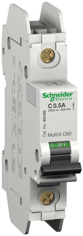
11 Protection Circuit protection C60 UL 489 circuit breakers (C and D curves) DB DB UL 489 / CSA C22.2 No / GB Tunnel terminal Ring terminal 240 V a 480Y / 277 V a 240 V a 480Y / 277 V a PB100981A_SE PB102035A_SE PB100985A_SE DB PB102035A_SE They provide: circuit overcurrent protection protection for wires against overloads and short circuits in final distribution manual control and isolation remote tripping, indications by the addition of auxiliaries. Breaking capacity: Rating (A) 25 C / 77 F Number of 18 mm (0.71 in.) poles Voltage Breaking capacity (ka rms) AIR Icu UL 489/CSA to 20 1P 277 V a P/3P 480Y/277 V a to 35 1P 120 V a V a P/3P 240 V a V a V a - 6 1P 60 V c P 125 V c CM901037E Version : /07/2014 9
12 Protection Circuit protection C60 UL 489 circuit breakers (C and D curves) Catalogue numbers Tunnel terminal connection 120 to 240 V a 480 Y / 277 V a Type 1P 2P 3P 1P 2P 3P DB V c DB DB DB V c DB DB Auxiliaries Remote indication and tripping, module CM Curve Curve Curve Curve Curve Curve Rating (In) C D C D C D C D C D C D MGN61300 MGN61333 MGN61311 MGN MGN61301 MGN61334 MGN61312 MGN61345 MGN61323 MGN MGN61302 MGN61335 MGN61313 MGN61346 MGN61324 MGN MGN61303 MGN61336 MGN61314 MGN61347 MGN61325 MGN MGN61304 MGN61337 MGN61315 MGN61348 MGN61326 MGN MGN61305 MGN61338 MGN61316 MGN61349 MGN61327 MGN MGN61306 MGN61339 MGN61317 MGN61350 MGN61328 MGN MGN61307 MGN61340 MGN61318 MGN61351 MGN61329 MGN MGN61308 MGN61341 MGN61319 MGN61352 MGN61330 MGN MGN61309 MGN61342 MGN61320 MGN61353 MGN61331 MGN MGN61310 MGN61343 MGN61321 MGN61354 MGN61332 MGN Width in 9 mm modules Accessories Module CM Ring terminal connection 120 to 240 V a 480 Y / 277 V a Type 1P 2P 3P 1P 2P 3P 60 V c V c DB DB DB DB DB DB Auxiliaries Remote indication and tripping, module CM Curve Curve Curve Curve Curve Curve Rating (In) C D C D C D C D C D C D MGN61366 MGN61399 MGN61377 MGN MGN61367 MGN61400 MGN61378 MGN61411 MGN61389 MGN MGN61368 MGN61401 MGN61379 MGN61412 MGN61390 MGN MGN61369 MGN61402 MGN61380 MGN61413 MGN61391 MGN MGN61370 MGN61403 MGN61381 MGN61414 MGN61392 MGN MGN61371 MGN61404 MGN61382 MGN61415 MGN61393 MGN MGN61372 MGN61405 MGN61383 MGN61416 MGN61394 MGN MGN61373 MGN61406 MGN61384 MGN61417 MGN61395 MGN MGN61374 MGN61407 MGN61385 MGN61418 MGN61396 MGN MGN61375 MGN61408 MGN61386 MGN61419 MGN61397 MGN MGN61376 MGN61409 MGN61387 MGN61420 MGN61398 MGN Width in 9 mm modules Accessories Module CM Version : /07/2014 CM901037E

13 Protection Circuit protection C60 UL 489 circuit breakers (C and D curves) Connection Type Rating Tightening torque Cu wires Screw-on connection for ring terminal PB100999A_SE PB101000A_SE Tunnel terminal 240 V a Ring terminal 240 V a PB102091A_SE PB102090A_SE Tunnel terminal 480Y / 277 V a Ring terminal 480Y / 277 V a Tunnel terminal 240 V a Tunnel terminal 480 Y / 277 V Ring terminal 480 Y / 277 V 240 V a 0.5 to 25 A 2.5 N.m (22 Ib.in.) A 3.5 N.m (31 Ib.in.) 0.5 to 10 A 0.8 N.m (7 Ib.in.) 15 to 25 A 1.6 N.m (14 Ib.in.) - 2 N.m (18 Ib.in.) (1) UL 486A (2) Single insulated ring terminal, UL or CSA certified. DB (1) (2) 2.5 to 25 mm 2 - (#14 #4 AWG) 2.5 to 35 mm 2 - (#14 #2 AWG) 1 or 2 wires, 1 to 1.5 mm 2 - (#18 #16 AWG) 1 or 2 wires, 2.5 to 6 mm 2 - (#14 #10 AWG) - Ø 5 mm DB Technical data DB DB DB Clips on to 35 mm DIN rail. Any installation position. IP40 Main characteristics Voltage rating 120 to 240 V a, 480 Y / 277 V a, 60 V and 125 V Insulation voltage (Ui) 500 V Pollution degree 3 Rated impulse withstand voltage (Uimp) 6 kv Thermal tripping Reference temperature 25 C Magnetic tripping ( ) C curve in alternating current 8.5 In ± 20 % in direct current 12 In ± 20 % D curve 12 In ± 20 % Utilization category - Limitation class 3 Rated breaking and making capacity on a single pole Icn1 = Icn (Icn1) Additional characteristics Degree of protection Device in modular enclosure IP40 / IPXXB ( 60529) Tunnel terminal connection IP20 / IPXXB 480 Y / 277 V a Ring terminal connection IP10 / IPXXA Endurance (O-C) Electrical 10,000 cycles Mechanical 20,000 cycles Operating temperature -30 C to +70 C Storage temperature -40 C to +80 C Tropicalization Treatment 2 (relative humidity of 95 % at 55 C) CM901037E Version : /07/
14 Protection Circuit protection C60 UL 489 circuit breakers (C and D curves) Weight (g/oz) Circuit breaker Type C60 UL 1P 110/3.88 2P 220/7.75 3P 330/11.64 Dimensions (mm) DB DB Tunnel terminal 240 V a Tunnel terminal 480Y / 277 V a Ring terminal 480Y / 277 V a DB Ring terminal 240 V a 12 Version : /07/2014 CM901037E

 25 C/77 F Number of Voltage Breaking capacity (ka rms) 18 mm AIR Icu (0.71 in.) poles UL 1077/CSA 60947-2 0.")
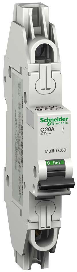
15 Protection Circuit protection C60 UL 1077 circuit breakers (B, C and D curves) DB DB DB UL1077 / CSA C22.2, / GB C60 UL circuit breakers are multi-standard circuit breakers which combine the following functions: circuit protection against short-circuit currents circuit protection against overload currents tripping and fault indication by the addition of auxiliaries. PB101029_ PB100980_ Rating (A) 25 C/77 F Number of Voltage Breaking capacity (ka rms) 18 mm AIR Icu (0.71 in.) poles UL 1077/CSA to 63 1P 240 V a P/3P/4P 240 V a P 277 V a V a - 3 2P/3P/4P 415 V a V a Y/277 V a 5-1P 60 V c P 65 V c 10-2P 125 V c Catalogue numbers C60 UL circuit breaker Type 1P 2P DB c DB Auxiliaries Remote indication and tripping, module CM Curve Curve Rating (In) B C D B C D Width in 9 mm 2 4 modules Accessories Module CM CM901039E Version : /07/
16 Protection Circuit protection C60 UL 1077 circuit breakers (B, C and D curves) Conformity with product standards UL 1077 additional protective devices, document #E CSA C22.2 no additional protective devices, document #E Catalogue numbers C60 UL circuit breaker Type 3P 4P E Sch 3P E Sch 3P Auxiliaries Remote indication and tripping, module CM Curve Curve Rating (In) B C D B C D Width in 9 mm 6 8 modules Accessories Module CM Version : /07/2014 CM901039E
 Connection kit for ring terminal cat. no. 17400 (option). DB122945 0.5 to 25 A 30 to 63 A 2.5 N.m (22 lb.in) 3.5 N.m (31 lb.")
17 Protection Circuit protection C60 UL 1077 circuit breakers (B, C and D curves) PB100997A_SE N UL 486A connections for copper wires, document #E Rating Tightening torque Without accessory With accessory Cu wires Screw-on connection for ring terminal (1) Connection kit for ring terminal cat. no (option). DB to 25 A 30 to 63 A 2.5 N.m (22 lb.in) 3.5 N.m (31 lb.in) 2.5 to 25 mm 2 (#14 #4 AWG) 2.5 to 35 mm 2 (#14 #2 AWG) Ø 5 mm Ø 5 mm (1) 2 set-screw connectors + 2 separators for terminals (upstream / downstream) cat. no DB Clips onto 35 mm DIN rail. Any installation position. IP40 Technical data Main characteristics Voltage rating Insulation voltage Pollution degree 3 Rated impulse withstand voltage (Uimp) 480Y/277 V, 60 V c and 125 V c 500 V 6 kv Thermal tripping Reference temperature 25 C Magnetic tripping B curve in alternating 4 In ± 20 % current in direct current 5.6 In ± 20 % C curve in alternating 8.5 In ± 20 % current in direct current 12 In ± 20 % D curve in alternating 12 In ± 20 % current Limitation class 3 Rated breaking and making capacity on a single pole Icn1 = Icn (Icn1) Additional characteristics Degree of protection Device in modular enclosure IP40 ( 60529) Tunnel terminal connection IP Y / 277 V a Ring terminal connection IP10 Endurance (O-C) Electrique 10,000 cycles Mécanique 20,000 cycles Operating temperature -30 C to +70 C Storage temperature -40 C to +80 C Tropicalization Treatment 2 (relative humidity 95 % at 55 C) Weight (g/oz) Type 1P 2P 3P 4P C60 UL 110/ / / /15.52 Dimensions (mm) DB DB DB DB DB C60 UL 1077 Kit for ring terminals CM901039E Version : /07/
 PB104013-34 PB104014-34 The C60H-DC supplementary protectors are used in direct current circuits (Industrial control and automations, transport, renewable")
 Rated voltage (Un) 250 V DC 500 V DC Number of poles 1P 2P Curve C C Number of 2 4 modules of 9 mm Diagrams DB116587")
18 DC circuit supplementary protectors for feeders / distribution systems C60H-DC C curve DB DB /EN , GB , UL1077 (Supplementary Protector TC 3) PB PB The C60H-DC supplementary protectors are used in direct current circuits (Industrial control and automations, transport, renewable energy...). They combine the following functions of circuit protection against short-circuit and overload currents, control and isolation. e Catalogue numbers C60H-DC Operating voltage V DC V DC (Ue) Rated voltage (Un) 250 V DC 500 V DC Number of poles 1P 2P Curve C C Number of 2 4 modules of 9 mm Diagrams DB DB Supply from above or below, observing the polarity Standards UL EN GB Breaking capacity 5 ka / 250 V DC 20 ka / 110 V DC 10 ka / 220 V DC 6 ka / 250 V DC Supply from above or Supply from below UL EN GB ka / 500 V DC 20 ka / 220 V DC 10 ka / 440 V DC 6 ka / 500 V DC Auxiliaries Remote indication and tripping, module CM Rating (A)* UL 1077, , EN , GB MGN61500 MGN MGN61501 MGN MGN61502 MGN MGN61503 MGN MGN61504 MGN MGN61505 MGN MGN61506 MGN MGN61508 MGN MGN61509 MGN MGN61510 MGN MGN61511 MGN MGN61512 MGN MGN61513 MGN MGN61514 MGN MGN61515 MGN MGN61517 MGN61537 Rating (A)* , EN , GB MGN61518 MGN MGN61519 MGN61539 Accessories Module CM * At 25 C / 77 F see temperature derating. 16 Version : /07/2014 CM901044E

19 DC circuit supplementary protectors for feeders / distribution systems C60H-DC (cont.) C curve DB Clip on DIN rail 35 mm. Technical data Tripping curves: C curve - Overcurrent protection for any type of application. Positive break indication - the green strip indicates that all the poles are open and allows work to be carried out on the downstream circuit in complete safety. Suitable for isolation as defined in / EN Increase in the service life of the product: thanks to fast closure independent of the speed of action on the handle. Current limitation in the event of a fault: fast opening of the contacts prevents the loads from being destroyed in the event of a short-circuit. DB DB DB Indifferent position of installation. t IP Main characteristics Rated service breaking capacity (Ics) 75 % of the ultimate breaking capacity (Icu) Power loss See module Magnetic tripping (Ii) 8.5 In (± 20 %) (compatible with curve C) Rated impulse withstand voltage (Uimp) 6 kv under frame Insulation voltage (Ui) 500 V DC Endurance (O-C) Electrical 3,000 cycles (where L/R=2 ms) 6,000 cycles where the circuit is resistive Mechanical 20,000 cycles Additional characteristics Pollution degree 3 Utilization category A (no delay in accordance with /EN standards) Degree of protection Device in modular IP40 ( 60529) enclosure Tropicalization Relative humidity: 95 % at 55 C / 131 F ( and GB ) Operating temperature -25 C to 70 C / -13 F to 158 F Storage temperature -40 C to 85 C / -40 F to 185 F t Details of minimum distance between circuit-breaker and earthed metal parts for circuit-breaker intended for use without enclosure. PB d Failure to match polarity during connection may lead to a fire hazard and/or serious injury. b The connection polarity must be observed (marked on the front panel). b Use only with direct current. b If two poles are used in series for the American network, use at least a 12 inch / 30 cm cable. Weight (g) Circuit-breaker Type 1P 2P C60H-DC 128 g / 4.51 oz 256 g / 9.03 oz Dimensions (mm/in) DB DB C60H-DC Kit for ring terminals CM901044E Version : /07/
20 DC circuit supplementary protectors for feeders / distribution systems C60H-DC (cont.) C curve Curves Tripping curves C curve as in standard The operating range of the magnetic release is as follows between 7 In and 10 In. The curves show the cold thermal tripping limits when poles are charged and the electromagnetic tripping limits with 2 charged poles. The curves are used without any derating. DB t (s) , I / In Short circuit current limiting 220 V with 1P, 440 V with 2P 250 V with 1P, 500 V with 2P DB ms DB ms Limited energy (A 2 s) Limited energy (A 2 s) Prospective current (ka rms) Prospective current (ka rms) Version : /07/2014 CM901044E
21 DC circuit supplementary protectors for feeders / distribution systems C60H-DC (cont.) C curve Curves (cont.) Thermal stress limitation curve 220 V with 1P, 440 V with 2P 250 V with 1P, 500 V with 2P DB DB Peak current (ka) Peak current (ka) Prospective current (ka rms) Prospective current (ka rms) 100 Temperature derating (according to UL 1077/ CSA22.2/ UL489A/ UL489/ standards) The maximum permissable current in a device depends on the ambient temperature in which it is placed. Ambient temperature is the temperature inside the enclosure or switchboard in which the devices have been installed. The reference temperature is in the coloured column. When several simultaneously operating devices are mounted side by side in a small enclosure, the temperature rise inside the enclosure causes a reduction in the current rating. A reduction cœfficient of the order of 0.8 must therefore be allocated to the rating (already derated if it depends on the ambient temperature). Temperature ( C) Ratings (A) CM901044E Version : /07/
22 DC circuit supplementary protectors for feeders / distribution systems C60H-DC (cont.) C curve DB Connection 14 mm 6.5 mm PZ2 Rating Without accessory With accessories Tightening Copper cables torque Rigid / Flexible or Stranded with ferrule 50 mm² Al terminal Screw-on connection for ring terminal Multi-cables terminal Rigid cables Flexible cables O-OFF O-OFF DB DB DB DB DB y 25 A 2.5 N.m / 22 lb.in > 25 A 3.5 N.m / 31 lb.in 1 to 25 mm 2 #18 - #4 AWG 1 to 35 mm 2 #18 - #2 AWG 1 to 16 mm 2 #18 - #6 AWG 1 to 25 mm 2 #18 - #4 AWG 50 mm 2 1 AWG - Ø 5 mm 3 x 16 mm 2 3 x 6 AWG 3 x 10 mm 2 3 x 8 AWG DB Multi-cables connection 14 mm 6.5 mm PZ2 Rating Without accessory Tightening 2 Copper cables 3 Multi-cables / Different wires torque Rigid / Stranded Flexible or with ferrule Flexible / Stranded Flexible / Stranded / Rigid DB DB DB O-OFF O-OFF y 25 A 2.5 N.m / 22 lb.in > 25 A 3.5 N.m / 31 lb.in 2 x 1 mm 2 to 2 x 10 mm 2 2 x 18 AWG - 2 x 8 AWG 2 x 1 mm 2 to 2 x 16 mm 2 2 x 18 AWG - 2 x 6 AWG 3 x 1 mm 2 3 x 18 AWG 3 x 4 mm 2 3 x 6 AWG 2 x 2.5 mm x 1.5 mm 2 2 x 13 AWG + 1 x 15 AWG 2 x 10 mm x 6 mm 2 2 x 8 AWG + 1 x 9 AWG 20 Version : /07/2014 CM901044E

23 Protection Earth leakage protection GFP - Ground Fault Protector UL PB101614A50_SE DB UL 1053 residual current circuit breakers already protected upstream by a short-circuit and overload protection device are used for: b control and disconnection of electric circuits b protection of people against electric shock by direct and indirect contacts b protection of installations against insulation faults. They comply with RCD standards UL 1053 and b Voltage Independent: electromechanical technology, ensure residual current protection down to 0 V. They guarantee: b enhanced continuity of supply, during a series of close lightning strokes, IT earthing system, equipment including interference suppression filters, variable speed controllers, frequency converters, electronic ballasts for lighting b enhanced earth leakage protection: in presence of harmonics or high frequency rejections. SI type GFPs are ideal for operation in environments with a humid atmosphere and/or polluted by aggressive agents: swimming pools, marinas, agri-food industries, water treatment stations, industrial sites, etc. /EN /EN : Voltage Independent UL 1053 GFP UL 1053 type AC SI Technical data Voltage rating +10 %, -15 % 2P 120 or 240 V a 60 Hz 230 or 240 V a 50 Hz 2P 480Y/277 V a 60 Hz 240 V a 60 Hz 230/400 or 240/415 V a 50 Hz 4P 480Y/277 V a 60 Hz 240 V a 60 Hz 230/400 or 240/415 V a 50 Hz Current rating (ln) at 40 C A Making and breaking capacity: rated residual current (IDm) A Rated impulse withstand voltage (Uimp) 6 kv Utilisation category AC 23A Level of immunity In current wave 8/20 µs: 3 kâ In dampened recurrent current wave 0.5 µs/100 khz: 200 A Short-circuit current withstand (IDc = Inc) 10 ka with 100 A gg upstream fuse Test button minimum operating 2P 113 V AC voltage 4P 189 V AC Phase-to-phase test circuit To avoid external bridging on use on three-phase network without neutral Locking possible in tripped position By padlocking facility (not supplied) Release with fixed sensitivity for all ratings Behaviour in case of voltage drop Earth fault indication Number of cycles (O-C) Tropicalisation Degree of protection as per Operating temperature Storage temperature Instantaneous release: UL 1053 : ±15 % : +0 %, -50 % Ensure residual current protection down to 0 V On front face by red mechanical indicator 20,000 cycles Treatment 2 (relative humidity: 95 % at 55 C) On front face: IP40/IPXXB Tunnel terminal connection: IP20/IPXXB -25 C to +60 C -40 C to +70 C UL 486A connections for copper wires, document #E Rating Tightening torque Cu wires DB IP20 IP40 25 to 100 A 3.5 N.m (31 lb.in) 2.5 to 35 mm 2 (#14 #2 AWG) DB Weight (g/oz) GFP UL 1053 type AC SI Type GFP 2P 220 / 7.7 4P 450 / 15.9 DB Dimensions (mm) 4 P 2 P CM902013E Version : /07/
 UL 61008 1053 120 or 240 V 230 or 240 V 240 V 480Y/277 V 230/400 or 240/415 V 25 26 30 60949 60969 4 86 100 60950 60971 260 300 60951-40 26 30 60952 60972 260 300 60954-63 26 30 60955 - Width in")
24 Protection Earth leakage protection GFP - Ground Fault Protector UL PB101614A38_SE DB Catalogue numbers GFP UL 1053 type AC SI AC type SI 2P Rating (A) Sensitivity Cat. no. (ma) UL or 240 V 230 or 240 V 240 V 480Y/277 V 230/400 or 240/415 V Width in mod. of 9 mm (0,354 in.) PB101615A38_SE DB AC type SI 4P Accessories Rating (A) Sensitivity (ma) UL Cat. no. 240 V 480Y/277 V 230/400 or 240/415 V Module CM Width in mod. of 9 mm (0,354 in.) Circuit breaker type C V C V C60 480Y/277 V QOU QO HDL 240 V a 277 V a 480Y/277 V a 120 or 240 V a 240 V a 120 or 240 V a 240 V a 240 V a 1P and 2P 3P 1P 2P 3P 1P and 2P 3P 1P and 2P 3P 2P GFP 25 A 25 A 20 A 20 A 20 A 25 to 70 A 25 to 100 A 25 to 70 A 25 to 100 A 25 to 50 A 2P 240 V a (1) P 480Y/277 V a (1) P 480Y/277 V a (1) (1) include all amperages of GFP 10 Max short-circuit Current withstand (ka) Coordination Short-Circuit Current Rating (SCCR) The Ground-Fault Protector GFP must be used with upstream overcurrent protection suitable for the circuit. GFP is suitable for use on a circuit capable of delivering not more than values (ka) below when protected by devices listed below. Overcurrent Protection Required for UL applications of GFP 22 Version : /07/2014 CM902013E

25 Protection Circuit protection Electrical auxiliaries for C60 UL devices DB DB DB DB Compliance with electrical auxiliaries standards For UL 489 circuit breaker File # For CSA C22.2 No. 5.2 circuit breakers File # For UL 1077 Supplementary Protectors File #E For CSA C22.2 No. 235-M04 Supplementary Protectors File # For and circuit-breakers. CE Marked. b The electrical auxiliaries are combined with C60 UL circuit breakers. b They perform the functions of tripping or remote indication of the position (open/closed/ tripped) of circuit breakers in the event of a fault. b They are installed by clip-on mounting (without tools) to the left of the circuit breaker. DB Indication Tripping Combination table Electrical auxiliaries Electrical auxiliaries Devices OF 1 SD or OF 2 (MN, MX+OF) maxi C60 UL d Tripping devices must be installed first. DB inch (4 mm) Connection Type Tightening torque Copper wires Rigid DB inch (9 mm) PZ1 Indication and tripping auxiliaries 9 lb.in (1 N.m) 2 wires, #16 AWG (1.5 mm 2 ) DB or 1 wires, #14 AWG (2.5 mm 2 ) CM907010E Version : /07/

 to indicate the \"open\" or \"closed\" position of the associated device Changeover contact indicating the \"open\" or \"closed\" position of the associated device")
26 Protection Circuit protection Electrical auxiliaries for C60 UL devices Tripping Indication Auxiliaries MN MX+OF OF SD Type Undervoltage release Shunt release Open/closed auxiliary Fault indicating switch contact Instantaneous With open/closed auxiliary contact PB SE-30 PB SE-30 PB SE-30 PB SE-30 Function Wiring diagrams Causes tripping of the device with which it is Causes tripping of the combined when its input voltage decreases (between associated device when 70 % and 35 % of Un) powered Prevents closing of the device until its input voltage Includes an open/closed has been restored contact (OF) to indicate the "open" or "closed" position of the associated device Changeover contact indicating the "open" or "closed" position of the associated device Changeover contact indicating the position of the associated device in the event of: vv an electrical fault vv actuation of the tripping auxiliary Same indication function as VISI-TRIP u < u > D1 D C2 C Use Emergency stoppage by normally closed push button Ensures the safety of power supply circuits for Emergency stoppage by normally open push button Remote indication of the Remote indication of the position of the Remote indication of tripping upon a fault in the associated device several machines by preventing untimely restarting position of the associated device associated device Catalogue numbers Technical specifications Rated voltage V AC, (Ue) 50/60 Hz V DC Mechanical status On front panel On front panel On front panel _ On front panel indicator, red Test function On front panel On front panel Width in 9 mm modules Current rating 3 A / 415 V AC 6 A / y 240 V AC 3 A /415 V AC 6 A / y 240 V AC Number of contacts 1 NO/NC 1 NO/NC 1 NO/NC Operating C temperature Storage temperature C DB Dimensions MN, MX+OF OF, SD 24 Version : /07/2014 CM907010E
27 CM907016E Version : /07/
28 Protection Circuit protection Earth leakage protection Accessories for C60 UL489, C60 UL1077, GFP UL1053, C60H-DC, devices Installation Accessories Rotary handle Plug-in base Padlocking device PB100137_SE-24 PB100138_SE-24 PB J_SE-20 Function Front or side control of 2, 3 and 4-pole circuit breakers or GFP Degree of protection: IP40 A complete rotary handle consists of: vv a circuit-breaker operating sub-assembly, cat. no , vv a handle cat. no or a handle cat. no Installation: vv the circuit-breaker operating sub-assembly cat. no is fixed to the circuit breaker or to the GFP Allows a circuit breaker to be quickly removed or replaced, without touching the connections Degree of protection: IP20 It consists of: vv a base to be fixed to a rail (or panel) vv 2 blades to be fixed in the device terminals Connection: tunnel terminals for cables up to 50 mm² (rigid) or 35 mm² (flexible) Installation: vv on backplate vv on a horizontal rail Centreline between two rows: 200 mm Used to padlock a device in the "open" or "closed" position Diameter of the padlock: 8 mm max. Locking in the ON position does not prevent the device from tripping in the event of a fault Isolation: in conformity with /EN vv the removable handle cat. no is mounted Only on the circuit breaker, without a Vigi device on the removable front panel or on the enclosure door vv the fixed handle cat. no is fixed to the or auxiliary Padlocking option (8 mm dia. padlock not supplied) front or side panel of the enclosure Cat. numbers Removable Fixed Operating (1 per pole) extended handle sub-assembly handle Set of Suitable for the following devices: C60 UL489 2P, 3P C60 UL1077 GFP UL1053 2P, 4P C60H-DC 2P 26 Version : /07/2014 CM907016E


, up to 6 mm² 3P: 1 x 26975")
29 Protection Circuit protection Earth leakage protection Accessories for C60 UL489, C60 UL1077, GFP UL1053, C60H-DC, devices (cont.) Safety Accessories Screw shield Terminal shield Interpole barrier Spacer PB _SE-38 DB PB Function Prevents all contact with the fixing screws The degree of protection becomes IP40 Sealable, max. diameter 1.2 mm Dividable Prevents all contact with the terminals Degree of protection becomes IP40 Sealable, max. diameter 1.2 mm 1P 2P Improves the Used to: insulation between the vv complete the rows connections: cables, vv separate the devices terminals, lugs, etc. Width: 1 x 9 mm module Allows that 2 cables are routed from one row to another (above and below), up to 6 mm² 3P: 1 x x P: 2 x Cat. numbers Set of 2 (4P dividable) 2 (for upstream/downstream terminal) 10 1 Suitable for the following devices: C60 UL489 C60 UL1077 GFP UL1053 C60H-DC 2P CM907016E Version : /07/
30 Protection Circuit protection Earth leakage protection Accessories for C60 UL489, C60 UL1077, GFP UL1053, C60H-DC, devices (cont.) Connection Accessories Multi-cable terminal 50 mm² Al terminal Screw-on connection for ring terminal Connection kit for ring terminals Function DB For 3 copper cables: Rigid up to 16 mm² Flexible up to 10 mm² DB For 16 to 50 mm² aluminium cables For lug tipped cables, front or rear mounting 5 mm For terminal up to 63 A, front or rear access (screw Ø 5 mm) It incorporates a "conductive" part and an "insulating" part which ensures the phase-to-phase clearance Cat. numbers Set of C60 UL489 C60 UL1077 GFP UL1053 C60H-DC Tightening torque 2 N.m 10 N.m 2 N.m Stripping length 11 mm 13 mm Tools to be used Diameter 5 mm or PZ2 Hc 1/5" or 5 mm Diameter 5 mm Diameter 5 mm Accessories Identification Clip-on terminal marker strip D_SE-23 DB DB DB DB N-23 Function For connection identification Cat. numbers 0: AB1-R0 1: AB1-R1 2: AB1-R2 3: AB1-R3 4: AB1-R4 5: AB1-R5 6: AB1-R6 7: AB1-R7 8: AB1-R8 9: AB1-R9 A: AB1-GA B: AB1-GB C: AB1-GC D: AB1-GD E: AB1-GE F: AB1-GF G: AB1-GG H: AB1-GH I: AB1-GI J: AB1-GJ Set of 250 C60 UL489 4 markers max. per pole C60 UL markers max. per pole GFP UL markers max. per pole C60H-DC 4 markers max. per pole K: AB1-GK L: AB1-GL M: AB1-GM N: AB1-GN O: AB1-GO P: AB1-GP Q: AB1-GQ R: AB1-GR S: AB1-GS T: AB1-GT U: AB1-GU V: AB1-GV W: AB1-GW X: AB1-GX Y: AB1-GY Z: AB1-GZ +: AB1-R12 -: AB1-R13 Blank : AB1-RV 28 Version : /07/2014 CM907016E


31 Protection Circuit protection Connection comusbars for C60 UL 489 circuit breakers DB Country approval pictograms The comusbars are used only for C60 circuit-breakers in conformity with standards UL 489, CSA C22.2 No or fitted with tunnel terminals. They perform distribution and subdistribution of the electric power supply and allow rapid assembly and disassembly of equipment. Connection accessories Comusbars Comusbar Accessories Insulated connector Tooth cover end-piece PB DB PB PB PB Function Use 1P x 240 V - 12 modules 3P x 480Y - 12 modules 3P 480Y - Can accept auxiliaries The comusbars make it easier to install Schneider Electric UL 489 circuit breakers They must not be cut Power supply by insulated connector Comusbar power supply Vertical incoming feeder For semi-rigid copper cable of 4 to 35 mm 2 (#1-#12 AWG) Tightening torque: 6 N.m (53 Ib.in) max. Number of poles 1P 2P 3P All All Voltage rating (Ue) 240 V AC 480Y/277 V AC 240 V CA 480Y/277 V AC 240 V AC 480Y/277 V AC 240 V AC 480Y/277 V AC Catalogue numbers * Number of 18 mm modules Set of Insulation of teeth remaining free Technical specifications Insulation voltage (Ui) 1000 V Impulse withstand voltage 12 kv (Uimp) Acceptable current at 40 C (Ie) 240 V : 100 A 480Y : 80 A Max. current per feeder 240 V : 35 A 480Y : 20 A Resistance to short-circuit Compatible with the breaking capacity of Schneider Electric modular circuit breakers currents Fire resistance Self-extinguishability 960 C 30 s/30 s Colour RAL 9001 RAL 1021 Standards UL508 UL486E * With spare spaces of 18 mm for electrical auxiliary DB Dimensions (mm) 213,6 DB ,6 17,8 5 17,8 165, ,4 111,8 199,4 140,6 167,6 129,1 240 V AC comusbar and connectors 480Y/277 V AC comusbar and connectors CM901040E Version : /07/
 Comusbar Shape ensuring perfect indexing in the circuit-breaker terminals Insulated connectors Clip")


 or vv two 9 mm electrical auxiliaries (OF, SD, etc.")
32 Protection Circuit protection Connection comusbars for C60 UL 489 circuit breakers (cont.) Comusbar Shape ensuring perfect indexing in the circuit-breaker terminals Insulated connectors Clip onto the comusbar's insulating material, which gives them very great stability Connect to the tunnel terminal of the circuit breaker: vv through the front on 480Y/277 V comusbars vv through the rear on 240 V comusbars Terminal tightening from the front PB PB PB DB Y/277 V comb busbar Phase separators ensuring electrical insulation Tooth cover endpieces The teeth left on standby can be insulated by tooth cover end-pieces 3P, 240 V comusbar - 12 modules 3P, 480Y/277 V comusbar - 12 modules PB DB Comusbar that can accept auxiliaries With spare spaces of 18 mm for electrical auxiliary: vv one 18 mm electrical auxiliary (MN, MX, etc.) or vv two 9 mm electrical auxiliaries (OF, SD, etc.) 3P, 480Y/277 V comusbar - 12 modules for auxiliaries 30 Version : /07/2014 CM901040E


33 Protection Circuit protection Connection comusbars for C60 UL 1077 circuit breakers DB DB DB The comusbars are used only for C60 circuit-breakers in conformity with standards UL 1077 / CSA C22.2 No / / GB They perform distribution and subdistribution of the electric power supply and allow rapid assembly and disassembly of equipment. Connection accessories Comusbars Comusbar Accessory Tooth cover end-piece Function The comusbars make it easier to install Schneider Electric UL 1077 circuit breakers Power supply directly in the cage of the circuit-breaker The Tooth Caps are insulated protectors which may be slipped onto the unused teeth of the comb busbar They come in strips with 1-pole spacing, but can be snapped apart to be used individually Number of poles 1P 2P 3P All Voltage rating (Ue) 480Y/277 V AC 480Y/277 V AC 480Y/277 V AC Catalogue numbers Number of 18 mm modules 12 (8.5 inches/216 mm) 12 (8.5 inches/216 mm) 12 (8.5 inches/216 mm) Set of Technical specifications Insulation voltage (Ui) 690 V Impulse withstand voltage (Uimp) 12 kv under 240 V 5 kv under 480Y/277 V or 277 V Acceptable current at 40 C (Ie) 63 A with 1 central power supply point 100 A with 2 power supply points DB DB N Power supply via cable directly in the cage of the device: vv cross section maxi: 3 AWG (25 mm 2 ) vv cross section mini: 10 AWG (5.27 mm 2 ) Resistance to short-circuit Compatible with the breaking capacity of C60 UL 1077 Schneider Electric modular circuit breakers currents Fire resistance Self-extinguishability 960 C 30 s/30 s Colour RAL 9001 RAL 1021 Dimensions (inches/mm) DB (216) 1.4 (35) 0.87 (22) 0.44 (11.2) 7.8 (198) 0.7 (18) 0.15 (3.8) 0.5 (13) 0.06 (1.5) CM907011E Version : /07/
34 Complementary technical information C60 limitation curve Thermal stress C60 UL 489 / CSA C22.2 No. 5-02, UL 1077 / CSA C22.2 No UL 489 / CSA C22.2 No. 5-02, UL 1077 / CSA C22.2 No Ue : y 277 V a (UL UL 1077) 1P Ue : y 277 V a 2, 3, 4P DB DB UL 1077 / CSA C22.2 No Ue : 480Y / 277 V a 2, 3, 4P DB Version : /07/2014 CM908004E
35 Complementary technical information C60 limitation curve Peak current C60 UL 1077 / CSA C22.2 No UL 489 / CSA C22.2 No. 5-02, UL 1077 / CSA C22.2 No Ue : y 240 V a (UL UL 1077) 1P Ue : y 240 V a 2, 3, 4P DB DB UL 1077 / CSA C22.2 No UL 1077 / CSA C22.2 No Ue : y 277 V a (UL 1077) 1P Ue : 480Y / 277 V a 2, 3, 4P DB DB CM908004E Version : /07/
36 Complementary technical information C60 tripping curves UL 489 Listed C60 Miniature Circuit Breakers / GB DB C60 UL489 Listed C60N - C curve - AC/DC s for I/In = s for I/In = 1.3 Operating range of the magnetic trip unit: B curve : vvin alternative current: 4 In ± 20 % vvin direct current: 5.6 In ± 20 % C curve : vvin alternative current: 8.5 In ± 20 % vvin direct current: 12 In ± 20 % D curve : vvin alternative current: 12 In ± 20 % vvin direct current: 18 In ± 20 % The curves represent: the thermal tripping limits at low temperatures (25 C), poles loaded. DB UL 489 Listed C60N - D curve - AC/DC s for I/In = s for I/In = t(s) 10 t(s) 10 1 AC 1 AC 0.1 DC 0.1 DC I / In I / In Version : /07/2014 CM908004E
37 Complementary technical information C60 tripping curves UL 1077 Recognized Supplementary Protectors / GB C60 UL 1077 Recognized C60 - B curve - AC/DC UL 1077 Recognized C60 - C curve - AC/ DC DB s for I/In = s for I/In = 1.3 DB s for I/In = s for I/In = t(s) 10 1 AC t(s) 10 1 AC 0.1 DC 0.1 DC I / In I / In DB UL 1077 Recognized C60 - D curve - AC/DC s for I/In = s for I/In = t(s) 10 1 AC 0.1 DC I / In CM908004E Version : /07/
38 Complementary technical information Temperature derating C60 UL 1077 / CSA C22.2 No UL 489 / CSA C22.2 No Influence of temperature on the operation Circuit breakers High temperatures A rise in temperature causes lowering of the thermal threshold (tripping on overload). Protection is still ensured: the tripping threshold remains lower than the current acceptable by the cable (I z ) To prevent nuisance tripping, it should be checked that this threshold remains higher than the maximum operating current (I B ) of the circuit, defined by: vvthe rated load currents, vvthe coefficients of expansion and simultaneity of use. If the temperature is sufficiently high for the tripping threshold to become lower than the operating current I B, switchboard ventilation should be provided for. Low temperatures A fall in temperature increases the thermal tripping threshold of the circuit breaker. There is no risk of nuisance tripping: the threshold remains higher than the maximum operating current of the circuit (I B ) demanded by the loads. It should be checked that the cable remains suitably protected, i.e. that its acceptable current (I z ) is higher than the values shown in the following tables (in amperes). When the ambient temperature could vary within a broad range, both these aspects must be taken into account: the difference between the maximum operating current of the circuit (I B ) and the tripping threshold of the circuit breaker for the minimum ambient temperature, the difference between the strength of the cable (I Z ) and the maximum tripping threshold of the circuit breaker for the maximum ambient temperature. Maximum permissible current The maximum current allowed to flow through the device depends on the ambient temperature in which it is placed. The ambient temperature is the temperature inside the enclosure or switchboard in which the devices are installed. The reference temperature is in a halftone colour for the different devices. When several devices operating simultaneously are mounted side by side in a small enclosure, a temperature rise in the enclosure results in a reduction in the operating current. A reduction coefficient of 0.8 will then have to be assigned to the rating (already derated, if applicable, depending on the ambient temperature). Example: Depending on the ambient temperature and the method of installation, the table below shows how to determine, for a C60 the operating currents not to be exceeded (reference temperature 25 C). The reference temperature is in half-tone colour. Rating (A) -30 C -25 C -20 C -15 C -10 C -5 C 0 C 5 C 10 C 15 C 20 C 25 C 30 C 35 C 40 C 45 C 50 C 55 C 60 C 65 C 70 C -22 F -13 F -4 F 5 F 14 F 23 F 32 F 41 F 50 F 59 F 68 F 77 F 86 F 95 F 104 F 113 F 122 F 131 F 140 F 149 F 158 F Version : /07/2014 CM908004E
Electrical auxiliaries for ic60, iid, idpn Vigi, isw-na, RCA and ARA
 for ic60, iid, idpn Vigi, isw-na, RCA and ARA b The electrical auxiliaries are combined with ic60 circuit breakers, iid residual current circuit breakers, remote tripping switch disconnector isw-na, RCA
C60PV-DC. IEC / EN e. Main characteristics Operating voltage (Ue) 800 V DC Rated insulation voltage (Ui) 1,000 V DC Breaking capacity (Icu)
 800 V DC Rated insulation voltage (Ui) 1,000 V DC Breaking capacity (Icu)") DC circuit supplementary protectors for photovoltaic C60PV-DC PB108403-50 The C60PV-DC is a DC circuit breaker dedicated to multi string photovoltaic. This circuit breaker is designed to protect the cables
DC circuit supplementary protectors for photovoltaic C60PV-DC PB108403-50 The C60PV-DC is a DC circuit breaker dedicated to multi string photovoltaic. This circuit breaker is designed to protect the cables
Section 4 Ground-Fault Protection Devices
 Multi 9 System Catalog Section 4Ground-Fault Protection Devices Section 4Ground-Fault Protection Devices Selection Table The Multi 9 System includes one UL Listed and three IEC rated product families that
MULTI 9 System Catalog UL Recognized C60N Supplementary Protectors
 UL Recognized C60N Supplementary Protectors B Curve C60N Supplementary Protectors 1 MG24110 MG24125 MG24140 MG24155 15 MG17406 MG17436 MG17461 1.2 MG17402 MG17432 16 MG24118 MG24133 MG24148 MG24163 1.5
MULTI 9 System Catalog UL Recognized NC100H Supplementary Protectors
 B Curve NC100H Supplementary Protectors Rating 1P 2P 3P 4P 80 MG27164 MG27175 MG27186 MG27197 MULTI 9 System Catalog UL Recognized NC100H Supplementary Protectors C Curve NC100H Supplementary Protectors
24973 Circuit Breaker MINIATURE CIRCUIT BREAKER, 440VAC, 10A, CIRCUIT BREAKER TYPE: STANDARD
 United States 24973 Circuit Breaker MINIATURE CIRCUIT BREAKER, 440VAC, 10A, CIRCUIT BREAKER TYPE: STANDARD Image not available Product Information Features and Specifications Approvals: IEC 60947-2 Rated
ic60n RCBO 30 ma IEC , IEC , AS/NZS
 ic60n RCBO 30 ma DB405571 Country approval pictograms IEC 61009-1, IEC 61009-2-2, AS/NZS 61009.1 PB110075-70 b The single-phase ic60n RCBO s self-contained residual current device provides protection of
60103 Circuit Breaker
 6003 Circuit Breaker United States MINIATURE CIRCUIT BREAKER, 20/240VAC, 2A, CIRCUIT BREAKER TYPE: STANDARD Image not available Product Information Features and Specifications Circuit Breaker Type: Standard
MG24434 Supplementary Protector SUPPLEMENTARY PROTECTOR, 240VAC, 16A, CIRCUIT BREAKER TYPE: STANDARD
 United States MG24434 Supplementary Protector SUPPLEMENTARY PROTECTOR, 240VAC, 16A, CIRCUIT BREAKER TYPE: STANDARD Product Information Features and Specifications For Use With: OEM Panels Approvals: UL
Issued February DATA SHEET 5SX2 MCB. Based on Siemens Industrial Control Catalog
 Issued February 2011 DATA SHEET 5SX2 MCB Based on Siemens Industrial Control Catalog General Data Trip characteristics Tripping characteristics acc. to EN 60 898 Tripping characteristic A, -5 Type A characteristic
1492-SP Supplementary Protectors
 Dual terminals provide wiring/bus bar flexibility and clamp from both sides to improve connection reliability Approval marks are easily visible on dome Terminal design helps prevent wiring misses Scratch-
MULTI 9 System Catalog
 MULTI 9 System Catalog Class 80 CONTENTS Page Schneider Electric Brands Section Introduction... Section UL Rated Protection Devices... Section IEC 097- Rated Protection Devices... Section IEC Rated Ground-fault
Mini Circuit Breakers, Fuse Blocks, and Electronic Circuit Protectors Specifications Bulletin Number 1492, 1692
 Technical Data Mini Circuit Breakers, Fuse Blocks, and Electronic Circuit Protectors Specifications Bulletin Number 1492, 1692 Topic Page 1489-M Miniature Circuit Breakers 1 1492-SP Supplementary Protectors
DX 3 MCB A / 16 ka 80 A to 125 A (1,5 module per pole)
") 87045 LIMOGES Cedex Telephone: +33 5 55 06 87 87 FAX: +33 5 55 06 88 88 DX 3 MCB 10000 A / 16 ka CONTENTS PAGES 1. Description - Use... 1 2. Range... 1 3. Overall dimensions... 1 4. Preparation - Connection...
87045 LIMOGES Cedex Telephone: +33 5 55 06 87 87 FAX: +33 5 55 06 88 88 DX 3 MCB 10000 A / 16 ka CONTENTS PAGES 1. Description - Use... 1 2. Range... 1 3. Overall dimensions... 1 4. Preparation - Connection...
ict contactors EN 61095, IEC 1095 Interference
 ict contactors DB23399 DB669 DB06604 Country approval pictograms EN 6095, IEC 095 ict contactors are available in two versions: b Contactors without manually-operated b Contactors with manually-operated.
Low voltage. NG to 160 A. Modular incoming circuit breakers and switch-disconnectors for DIN-panel installation.
 Low voltage NG160 16 to 160 A Modular incoming circuit breakers and switch-disconnectors for DIN-panel installation Catalogue 2010 NG160 circuit breaker Ready to install NG160 General contents Presentation
C60 UL 489 / CSA C22.2 No IEC / GB
 Main functions of UL 89 circuit breaker: b protection of circuits against: v short circuit currents v overload currents b control b isolation Various applications: b semi-conductors b electronic machinary
The right solution for every home
 Domae Household switchboards The right solution for every home Household guide 2002 Building a New Electric World. Household switchboards Domae The right solution for every home Household guide 2002 Building
FAZ Supplementary Protectors, FAZ Miniature Circuit Breakers, P2 Disconnect Switches Overview
 FAZ Supplementary Protectors, FAZ Miniature Circuit Breakers, P2 Disconnect Switches Overview Supplementary Protectors / Miniature Circuit Breakers Page System overview 10/003 10/001 Supplementary protectors
Multi 9 System Catalog
 Multi 9 System Catalog Catalog 0860CT00 R07/4 04 Class 860 CONTENTS CONTENTS Description............................................. Page Description Page Introduction..................................................7
MULTI 9 System Catalog
 MULTI 9 System Catalog Class 80 CONTENTS Schneider Electric Brands Description Page SectionIntroduction... Section UL 89 Listed Circuit Breakers and UL 77 Recognized SupplementaryProtectors... SectionIEC097-RatedProtectionDevices...
TeSys IEC Contactors and Overload Relays
 TeSys IEC Contactors and Overload Relays Making High-Fault Short-Circuit Current Ratings Simple Schneider Electric is an industry leader in IEC contactors and overload relays, and is recognized as the
Close Protection from Moeller. miniature branch circuit breakers miniature supplementary protectors
 Close Protection from Moeller miniature branch circuit breakers miniature supplementary protectors FAZ branch circuit breakers General Information... Selection Tables Trip Characteristic C - Box terminals...
C C CIRCUIT-BREAKERS Moulded-case (MCCB), general. 1. Introduction. 2. General description
, general. 1. Introduction. 2. General description") CIRCUIT-BREAKERS C C81-21 CIRCUIT-BREAKERS - Contents 1. Introduction 2. General description 3. Rated voltages 3.1 Rated operational voltage (U e ) 3.2 Rated impulse withstand voltage (U imp ) 3.3 Rated
CIRCUIT-BREAKERS C C81-21 CIRCUIT-BREAKERS - Contents 1. Introduction 2. General description 3. Rated voltages 3.1 Rated operational voltage (U e ) 3.2 Rated impulse withstand voltage (U imp ) 3.3 Rated
Bulletin 1489 Circuit Breakers. Selection Guide
 Bulletin 1489 s Selection Guide Overview/Description Bulletin 1489-A s Energy-limiting design protects downstream components better than conventional breakers during short circuits Field-mountable options
OTEC Miniature Circuit Breakers (MCB) OTEC Miniature Circuit Breakers (MCB) OTEC Miniature Circuit Breakers (MCB) Areas of Application
 OTEC Miniature Circuit Breakers (MCB) OTEC Miniature Circuit Breakers (MCB) Areas of Application") Miniature Circuit Breakers Areas of Application Miniature circuit breakers (MCBs) of the N-System primarily protect cables and conductors against overload and short circuit. Thus, they also protect electrical
Miniature Circuit Breakers Areas of Application Miniature circuit breakers (MCBs) of the N-System primarily protect cables and conductors against overload and short circuit. Thus, they also protect electrical
Control Circuit and Load Protection Products
 Selection Guide Control Circuit and Load Protection Products Bulletin Numbers 188, 1489, 1492, 1692 Circuit Protection Portfolio 1489-M Circuit Breakers Approved for branch circuit protection in the United
MOTOR PROTECTION CIRCUIT BREAKERS
 MOTOR PROTECTION CIRCUIT BREAKERS PAGE -2 PAGE -2 SMA Thermal trip adjustment ranges 9-32A (5 choices) Breaking capacity Icu at 400V: 50kA Suitable for mounting in consumer switchboards with minimum 58mm
UL 489 DIN Rail Miniature Circuit Breakers
 UL 489 DIN Rail Miniature Circuit Breakers Product Overview................................................ 2 Product Selection................................................ 4 Accessories.....................................................
Miniature Circuit Breakers for Railway Applications
 Siemens AG 00 for Railway Applications BETA Low-Voltage Circuit Protection The miniature circuit breakers are used in fixed railway systems and rolling stock for protecting system components against overcurrent
UL 489 DIN Rail Miniature Circuit Breakers
 UL 9 DIN Rail Miniature Circuit Breakers Product Overview................................................ Product Selection................................................ Accessories.....................................................
1.3. Miniature Circuit Breakers and Supplementary Protectors. Contents. WMZS Circuit Breaker. UL 1077 DIN Rail Supplementary Protectors
 . Miniature Circuit Breakers and Supplementary Protectors UL 077 DIN Rail Supplementary Protectors WMZS Circuit Breakers Contents Description WMZS Circuit Breaker Standards and Certifications................
ST 200 M data sheet System pro M compact miniature circuit breakers for supplementary protection acc. to UL 1077
 MINIATURE CIRCUIT BREAKERS ST 200 M data sheet System pro M compact miniature circuit breakers for supplementary protection acc. to UL 1077 The ST 200 M miniature circuit breaker provides supplementary
Low voltage. Acti 9. the efficiency you deserve. Catalogue 03/2016
 Low voltage Acti 9 the efficiency you deserve Catalogue 03/2016 schneider-electric.com 1 and 2 LV surge s 1 and 2 LV surge s (cont.) The 1 range of surge s meets the normative withstand capability of wave
Selection Guide. Control Circuit and Load Protection. Allen-Bradley 1489-M2C020
 Selection Guide Control Circuit and Load Protection Circuit Protection Portfolio 1489-M Circuit Breakers Approved for branch circuit protection in the United States and Canada, and certified as Miniature
J7MN. Ordering Information. Motor Protection Circuit Breaker. Model Number Legend. MPCB system. Options. Motor Protection Circuit Breaker J7MN I-1
 Motor Protection Circuit Breaker J7MN ) MPCB system Rotary and switch types Rated operational current 32 A, 63 A and 00 A Switching capacity up to 00 ka/400 V Fixed short-circuit release = 3 x I u Overload
Application Switchgear for industrial and advanced commercial applications. U e V AC 240/ (per pole) I cs 7,5 ka
 I cs 7,5 ka") DATASHEET - FAZ-C16/1 Miniature circuit breaker (MCB), 16A, 1p, C-Char, AC Part no. FAZ-C16/1 Catalog No. 278561 Eaton Catalog No. FAZ-C16/1 EL-Nummer 0001695154 (Norway) Similar to illustration Delivery
DATASHEET - FAZ-C16/1 Miniature circuit breaker (MCB), 16A, 1p, C-Char, AC Part no. FAZ-C16/1 Catalog No. 278561 Eaton Catalog No. FAZ-C16/1 EL-Nummer 0001695154 (Norway) Similar to illustration Delivery
Motor-protective circuit-breaker, 3p, Ir=16-25A, screw connection. Product range PKZM4 motor protective circuit-breakers up to 65 A
 DATASHEET - PKZM4-25 Delivery program Motor-protective circuit-breaker, 3p, Ir=16-25A, screw connection Part no. PKZM4-25 Catalog No. 222352 Eaton Catalog No. XTPR025DC1NL EL-Nummer 0004355158 (Norway)
UL 489 Cable-In / Cable-Out Branch Circuit Breaker
 Product Overview UL 9 Cable-In / Cable-Out Branch Circuit Breaker PRODUCT OVERVIEW Optimum and Efficient Protection Features Complete range of UL 9 listed DIN rail mounted miniature circuit breakers up
1.2. Miniature Circuit Breakers and Supplementary Protectors. Contents. WMZ Circuit Breaker. UL 489 DIN Rail Miniature Circuit Breakers
 .2 WMZ Circuit Breakers Contents Description WMZ Circuit Breaker Standards and Certifications.............. Selection................ Product Selection....................... Accessories...........................
DSE201, DSE201 M Compact design with enhanced protection
 DSE20, DSE20 M Compact design with enhanced protection Ultimate safety DSE20 and DSE20 M: the highest level of reliability The P+N electronic residual current circuit-breakers with overcurrent protection
SOCOMEC SIRCOVER MANUALLY OPERATED CHANGEOVER SWITCHES
 MANALL OPERATED CHANGEOER SWITCHES are manually operated multipolar changeover switches. They changeover between two low voltage power circuits under load and provide safety disconnection. Application:
low voltage GLOBAL CATALOGUE RANGE Motor Control Contactors - Thermal Overload Relay s - Manual Motor Starters
 CTLOGUE GLOBL RNGE 2. Motor Control Contactors - Thermal Overload Relay s - Manual Motor Starters 2. 2. Product Overview. 2.2 Overload Relay Setting Range 2. - 2.8 Product Specifications 2.9-2. Contactor
SIRCO Load break switches for power distribution from 125 to 5000 A
 The solution for Load break switches sirco_456_a_1_cat > Main switchboard > Distribution panel > Emergency breaking > Network coupling > Local safety breaking sirco-ac_001_a_1_cat SIRCO 3 x 250 A direct
RM17UB3. Product data sheet Characteristics. voltage control relay RM17-U - range V AC. Main. Complementary
 Characteristics voltage control relay RM17-U - range 183..528 V AC Main Range of product Product or component type Relay type Product specific application Relay name Relay monitored parameters Time delay
Selection Guide. Control Circuit and Load Protection
 Selection Guide Control Circuit and Load Protection Circuit Protection Portfolio 1489-M Circuit Breakers Approved for branch circuit protection in the United States and Canada, and certified as Miniature
Protection Equipment
 Protection Equipment Price groups 41B, 41E, 41F, 41G, 41H, 41J, 42F, 42J, 143, 401 /2 Introduction Motor starter protectors/ circuit breakers SIRIUS 3RV2 motor starter protectors up to 40 A / General data
ATS22D88S6U. ATS22D88S6U soft starter-ats22-control110v-power 208V(25hp)/230V(30hp)/460V(60hp)/575V(75hp) Product data sheet Characteristics.
/230V(30hp)/460V(60hp)/575V(75hp) Product data sheet Characteristics.") Characteristics soft starter-ats22-control110v-power 208V(25hp)/230V(30hp)/460V(60hp)/575V(75hp) Main Range of product Altistart 22 Product or component type Product destination Product specific application
Characteristics soft starter-ats22-control110v-power 208V(25hp)/230V(30hp)/460V(60hp)/575V(75hp) Main Range of product Altistart 22 Product or component type Product destination Product specific application
29 $ Manual Motor Starters FREESHIPPING. MOTOR CONTROLS 25. Features: MMS-32H Frame. MMS-63H Frame.
 www.factorymation.com/motorcontrols MOTOR CONTROLS 25 Manual Motor Starters High interrupt capacity Din rail and surface mounting Lockable handle (OFF position) IP20 finger safe terminals Class 10 thermal
IDE Load break switches for machine control Remotely trippable switch from 32 to 160 A
 The solution for Load break switches > Industry. > Non critical buildings. > Public Access Sites. > High Rise Buildings. ide_021_a_1_cat ide_022_a_1_cat IDE 4x40 A External operation IDE 4x40 A Direct
RM35UB3. Product data sheet Characteristics. voltage control relay RM35-U - range V AC. Main. Complementary
 Characteristics voltage control relay RM35-U - range 194..528 V AC Main Range of product Product or component type Relay type Product specific application Relay name Relay monitored parameters Time delay
Selection Guide. Control Circuit and Load Protection
 Selection Guide Control Circuit and Load Protection Circuit Protection Portfolio 1489-M Circuit Breakers Approved for branch circuit protection in the United States and Canada, and certified as Miniature
Application Switchgear for industrial and advanced commercial applications. U e V AC 277/480 Y V DC 60
 DATASHEET - FAZ-C5/2-RT Miniature circuit breaker (MCB), 5A, 2p, C-Char, AC Part no. FAZ-C5/2-RT Catalog No. 102203 Eaton Catalog No. FAZ-C5/2-RT EL-Nummer 1691799 (Norway) Similar to illustration Delivery
Voltage monitoring relays CM-ESS.1 For single-phase AC/DC voltages
 Data sheet Voltage monitoring relays CM-ESS.1 For single-phase AC/DC voltages The CM-ESS.1 is an electronic voltage monitoring relay that provides reliable monitoring of voltages as well as detection of
3 Pole Contactors with AC operating coils
 1 3 Pole Contactors with AC operating coils Characteristics General Characteristics Switching Current 9A ~ Rated insulation voltage (Ui) (Conforming to IEC 158-1) V 750 IEC 60947-4 V 1000 Conforming to
Datasheet - SRB 402EM-24V
 Print - Create PDF - Create EXCEL file 20.04.2011-18:31:35h Datasheet - SRB 402EM-24V Output expanders / SRB 402EM Expander module for contact expansion 4 safety contacts, STOP 0 2 Signalling outputs (Minor
ABE7R16S210 sub-base - soldered electromechanical relays ABE7-16 channels - relay 10 mm
 Characteristics sub-base - soldered electromechanical relays ABE7-16 channels - relay 10 mm Main Range of product Product or component type [Us] rated supply voltage Number of channels 16 Number of terminal
NF44E-.. / NFZ44E-.. Contactor Relays AC / DC Operated - with Screw Terminals
 Technical Datasheet 1SBC1010D0201 28/03/11 NFE-.. / NFZE-.. Contactor Relays AC / DC Operated - with Screw Terminals NF(Z) contactor relays are used for switching auxiliary and control circuits. NF(Z)
Supplementary Circuit Protectors Type GSB63
 Supplementary Circuit Protectors Type GSB63 l Protection of circuits against short circuit and overload currents l UL1077 supplementary protection l 1,, 3 and 4 pole arrangements l 13 amperage sizes up
Allen-Bradley 1492-RCDA4A40
 Dual terminals provide wiring/bus bar flexibility and clamp from both sides to improve connection reliability Suitable for DIN Rail mounting Approval marks are easily visible on dome Terminal design helps
AThink future. Switch to green. Mini Panel Board. Cost-effective, space-saving board up to 400A.
 www.moeller.co.uk Mini Panel Board Cost-effective, space-saving board up to 400A Product Catalogue and Selection Guide Mini Panel Board Miniature Circuit Breakers Moulded Case Circuit Breakers XBoard Consumer
Electronic timer CT-ARS.11 OFF-delayed without auxiliary voltage with 1 c/o (SPDT) contact
 contact") Data sheet Electronic timer CT-ARS.11 OFF-delayed without auxiliary voltage with 1 c/o (SPDT) contact The CT-ARS.11 is an electronic timer from the CT-S range with true OFF-delay. It provides 7 time ranges
Data sheet Electronic timer CT-ARS.11 OFF-delayed without auxiliary voltage with 1 c/o (SPDT) contact The CT-ARS.11 is an electronic timer from the CT-S range with true OFF-delay. It provides 7 time ranges
RE17LAMW on-delay timing relay - 1 s..100 h V AC/ DC - solid state output
 Characteristics on-delay timing relay - 1 s..100 h - 24..240 V AC/ DC - solid state output Main Range of product Product or component type Discrete output type Width Component name Time delay type Time
ATS22D75S6 soft starter-ats22-control 220V-power 230V(18.5kW)/ V(37kW)/500V(45kW)
/ V(37kW)/500V(45kW)") Characteristics soft starter-ats22-control 220V-power 230V(18.5kW)/400...440V(37kW)/500V(45kW) Price* : 683.00 GBP Main Range of product Altistart 22 Product or component type Product destination Product
Characteristics soft starter-ats22-control 220V-power 230V(18.5kW)/400...440V(37kW)/500V(45kW) Price* : 683.00 GBP Main Range of product Altistart 22 Product or component type Product destination Product
Circuit Breakers Type CTI 25M, CTI 45MB
 Data sheet Circuit Breakers Type CTI 25M, CTI 45MB Circuit breakers for short circuit and overload protection of motor applications cover the current range 0.1 45 A (AC-3 rating). The product range is
Applying branch circuit breakers and supplementary protectors in North America
 Product Application AP01102005E WMZT WMZS Applying branch circuit breakers and supplementary protectors in North America Introduction Eaton offers two types of miniature circuit breakers for use in North
Approved Standards. Motor Protection Circuit Breaker (MPCB) J7MN. MPCB system (motor protection CLASS 10) Auxiliary contact modules.
 J7MN. MPCB system (motor protection CLASS 10) Auxiliary contact modules.") Motor Protection Circuit Breaker (MPCB) J7MN MPCB system (motor protection CLSS 0) Rotary and switch types Rated operational current = 2, 25, 50 and 00 Switching capacity up to 2.5 = 00 k/400 V Fixed short-circuit
Motor Protection Circuit Breaker (MPCB) J7MN MPCB system (motor protection CLSS 0) Rotary and switch types Rated operational current = 2, 25, 50 and 00 Switching capacity up to 2.5 = 00 k/400 V Fixed short-circuit
Electronic timer CT-ARS.11
 2CDC 251 088 F0t07 Features Rated control supply voltage 24 240 V AC/DC Single function OFF delay timer without auxiliary voltage One device includes 7 time ranges (0.05 s 10 min) 1 c/o (SPDT) contact
ABE7R16S210 sub-base - soldered electromechanical relays ABE7-16 channels - relay 10 mm
 Characteristics sub-base - soldered electromechanical relays ABE7-16 channels - relay 10 mm Main Range of product Product or component type [Us] rated supply voltage Number of channels 16 Number of terminal
RE17LCBM off-delay timing relay - control - 1 s..100 h V - solid state output
 Characteristics off-delay timing relay - control - 1 s..100 h - 24..240 V - solid state output Main Range of product Product or component type Discrete output type Width Component name Time delay type
RB60 RANGE. Miniature circuit breakers
 RB60 RANGE Miniature circuit breakers POWER 2015 RB60 range Miniature circuit breakers Miniature circuit breakers for circuit protection The miniature circuit breakers RB60 are designed for the protection
RM17UAS. Product datasheet Characteristics. voltage control relay RM17-U - range V DC. Main. Complementary. Price* : 70.
 Characteristics voltage control relay RM17-U - range 9..15 V DC Price* : 70.64 GBP Main Range of product Product or component type Relay type Product specific application Relay name Relay monitored parameters
ATS22D75S6U. Main. Range of product Altistart 22. Component name. Factory setting current. Utilisation category. IP degree of protection
 Product datasheet Characteristics ATS22D75S6U Complementary Assembly style Function available Supply voltage limits Main Range of product Altistart 22 Product or component type Product destination Product
63 to 125 A. Functions. Conformity standards. General characteristics. Changeover switches SIRCO VM1 changeover switches.
 comut_004_a_1_cat Changeover switches switches 63 to 125 A switches are manually operated three or four pole switches. They provide, source inversion or switching under load between two low voltage power
Electronic timer CT-ERS.12 ON-delayed with 1 c/o (SPDT) contact
 contact") Data sheet Electronic timer CT-ERS.12 ON-delayed with 1 c/o (SPDT) contact The CT-ERS.12 is an electronic timer from the CT-S range with ON-delay and 10 time ranges. All electronic timers from the CT-S
Data sheet Electronic timer CT-ERS.12 ON-delayed with 1 c/o (SPDT) contact The CT-ERS.12 is an electronic timer from the CT-S range with ON-delay and 10 time ranges. All electronic timers from the CT-S
Datasheet - SRB 301LC/B-24V
 27.01.2016-00:27:16h Datasheet - SRB 301LC/B-24V Guard door monitors and Safety control modules for Emergency Stop applications / General Purpose safety controllers (Series PROTECT SRB) / SRB 301LC/B Fit
Product Guide. UL 1077 DIN Rail Supplementary Protectors
 Product Guide UL 0 DIN Rail Supplementary Protectors UL 0 DIN Rail Supplementary Protectors Product Overview... Product Selection WMZS B Curve ( X I n Current Rating)..............................................
Applying branch circuit breakers and supplementary protectors in North America
 Supersedes June 2017 FAZ-NA-L FAZ-NA FAZ Applying branch circuit breakers and supplementary protectors in North America Introduction Eaton offers three types of miniature circuit breakers for use in North
Description. Installation. Power supply
 Air circuit breakers Special versions Series MEGT07 0V/500V/DC 50 up to 5000 A The air circuit breakers MEGT07 are suitable for use as disconnecting switch in DC distributions up to a rated voltage of
ATS22D17Q soft starter-ats22-control 220V-power 230V(4kW)/ V(7.5kW)
/ V(7.5kW)") Characteristics soft starter-ats22-control 220V-power 230V(4kW)/400...440V(7.5kW) Main Range of product Altistart 22 Product or component type Product destination Product specific application Component
Characteristics soft starter-ats22-control 220V-power 230V(4kW)/400...440V(7.5kW) Main Range of product Altistart 22 Product or component type Product destination Product specific application Component
Circuit Breakers, Type CTI 25M, CTI 45MB, CTI 100
 MAKING MODERN LIVING POSSIBLE Data sheet Circuit Breakers, Type CTI 25M, CTI 45MB, CTI 100 Circuit breakers for short circuit and overload protection of motor applications cover together with the circuit
Motor protection circuit breakers
 Wide adjustment range 0. to 00A IEC breaking capacity Icu 50kA (400V) up to 00A Suitable for isolation Comprehensive line of accessories Magnetic-only version Automatic trip indicators High reliability
WMS SUPPLEMENTARY PROTECTORS
 WMS Supplementary Protectors Overview WMS SUPPLEMENTARY PROTECTORS Product Specification The WMS Supplementary Protector is a dual-rated product for both AC and DC supplies, in accordance with UL 1077
ATS22D62Q soft starter-ats22-control 220V-power 230V(15kW)/ V(30kW)
/ V(30kW)") Characteristics soft starter-ats22-control 220V-power 230V(15kW)/400...440V(30kW) Main Range of product Altistart 22 Product or component type Product destination Product specific application Component
Characteristics soft starter-ats22-control 220V-power 230V(15kW)/400...440V(30kW) Main Range of product Altistart 22 Product or component type Product destination Product specific application Component
Zelio Control-modular measurement and control relays 1
 Presentation, description 1 106439 RM35 TM111MW Presentation Motor temperature measurement and 50MW and RM35 TM250MW monitor the following, on 3-phase supplies: correct sequencing of phases L1, L2 and
Electronic timer CT-APS.21 OFF-delayed with 2 c/o (SPDT) contacts
 contacts") Data sheet Electronic timer CT-APS.21 OFF-delayed with 2 c/o (SPDT) contacts The CT-APS.21 is an electronic timer from the CT-S range with OFF-delay. It provides 10 time ranges and a continuous rated control
Data sheet Electronic timer CT-APS.21 OFF-delayed with 2 c/o (SPDT) contacts The CT-APS.21 is an electronic timer from the CT-S range with OFF-delay. It provides 10 time ranges and a continuous rated control
XB7EV07BP round pilot light Ø 22 - clear - integral LED - 24 V - screw clamp terminals
 Characteristics round pilot light Ø 22 - clear - integral LED - 24 V - screw clamp terminals Complementary Height Width Depth Terminals description ISO n 1 Product weight Main Range of product Product
Electronic timer CT-ARS.21 OFF-delayed without auxiliary voltage with 2 c/o (SPDT) contacts
 contacts") Data sheet Electronic timer CT-ARS.21 OFF-delayed without auxiliary voltage with 2 c/o (SPDT) contacts The CT-ARS.21 is an electronic timer from the CT-S range with true OFF-delay. It provides 7 time ranges
Data sheet Electronic timer CT-ARS.21 OFF-delayed without auxiliary voltage with 2 c/o (SPDT) contacts The CT-ARS.21 is an electronic timer from the CT-S range with true OFF-delay. It provides 7 time ranges
Bulletin 290/291 ArmorStart LT Distributed Motor Controllers Specifications
 Power Circuit Control Circuit (External Source) Control Circuit (Internal Source) Short Circuit Current Rating (SCCR) Application Electrical Ratings Three-phase Number of Poles 3 Input Power Terminals
PowerPact Q-Frame Molded Case Circuit Breakers and Switches (Types QB, QD, QG and QJ)
") PowerPact Q-Frame Molded Case Circuit Breakers and Switches (Types QB, QD, QG and QJ) Catalog Class 0CT00R/0 0 CONTENTS Description..............................................Page Description.............................................
PowerPact Q-Frame Molded Case Circuit Breakers and Switches (Types QB, QD, QG and QJ) Catalog Class 0CT00R/0 0 CONTENTS Description..............................................Page Description.............................................
Datasheet SRB301ST 24V (V.2)
") 26.10.2016 05:03:31h Datasheet SRB301ST 24V (V.2) Guard door monitors and Safety control modules for Emergency Stop applications / General Purpose safety controllers (Series PROTECT SRB) / SRB301ST Suitable
26.10.2016 05:03:31h Datasheet SRB301ST 24V (V.2) Guard door monitors and Safety control modules for Emergency Stop applications / General Purpose safety controllers (Series PROTECT SRB) / SRB301ST Suitable
RM17TG. Main. Product or component type. Product specific application. Relay monitored parameters. Switching capacity in VA
 Characteristics phase control relay RM17-T - range 183..484 V AC Main Range of product Product or component type Relay type Product specific application Relay name Relay monitored parameters Switching
RTU500 series Data Sheet Power Supply CP-E 24/2.5
 Data Sheet Power Supply CP-E 24/2.5 Power Supply CP-E 24/2.5 Application The primary switch mode power supply offers two voltage input ranges. This enables the supply with AC or DC. Furthermore it is equipped
Miniature Circuit Breakers and Supplementary Protectors. Contents
 . Optimum and Efficient Protection for Every Application Product Overview Features Optimum product quality, tested reliability and safety stand for best protection of personnel, installations and plant.
Switch Disconnectors, Main and EMERGENCY-STOP Switches
 General data Overview Siemens G 2010 1 2 3 NSE0_01931b 4 5 6 7 1 uxiliary switch (3SB for 3K; 3KX for 3KE) 2 IP20 terminal cover (Operator side) 3 3K switch disconnector 4 rcing contacts (only for 3KE)
Contact protection relay
 Contact protection relay Ordering details SVR 450 08 F0000 The protects sensitive control contacts from excessive load. It can be used with latching function or without. Bounce time of control contacts
Disconnect Switches. Safe Switching and Disconnecting
 IB105-UK_U1_U4_Pfade.indd 2-3 14.04.2005, 16:51:30 Disconnect Switches Safe Switching and Disconnecting Disconnect Switches from Salzer are hand-operated switchgear for main circuits and are offered as
RM35TF V AC
 Characteristics multifunction phase control relay RM35-T - range 194..528 V AC Main Range of product Product or component type Relay type Product specific application Relay name Relay monitored parameters
ATS22C21S6U softstarter-ats22-control110vpower208v(60hp)/230v(75hp)/460v(150hp)/575v(200hp)
/230v(75hp)/460v(150hp)/575v(200hp)") Characteristics softstarter-ats22-control110vpower208v(60hp)/230v(75hp)/460v(150hp)/575v(200hp) Main Range of product Altistart 22 Product or component type Product destination Product specific application
Characteristics softstarter-ats22-control110vpower208v(60hp)/230v(75hp)/460v(150hp)/575v(200hp) Main Range of product Altistart 22 Product or component type Product destination Product specific application
ZBRN1 access point- 2 RJ V AC/DC-4 displays-5 LEDs-Eth-Modbus-wireless radio
 Characteristics access point- 2 RJ45-24..240V AC/DC-4 displays-5 LEDs-Eth-Modbus-wireless radio Product availability : Stock - Normally stocked in distribution facility Price* : 400.00 USD Main Range of