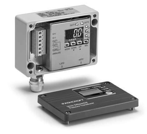
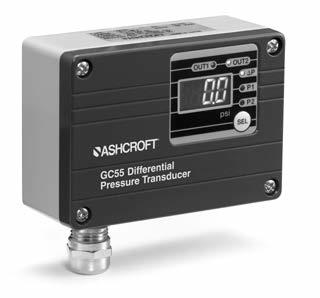
Installation and Maintenance Instructions for GC55 Differential Pressure Transducer Version 1.0 5/11
|
|
|
- Alicia Nicholson
- 5 years ago
- Views:
Transcription
1 Installation and Maintenance Instructions for GC55 Differential Pressure Transducer Version 1.0 5/ Ashcroft Inc. 250 East Main Street, Stratford, CT USA Tel: , Fax: All sales subject to standard terms and conditions of sale. I&M Rev. C 5/11
2 2
3 WARNING! READ BEFORE INSTALLATION 1. GENERAL: A failure resulting in injury or damage may be caused by excessive overpressure, excessive vibration or pressure pulsation, excessive instrument temperature, corrosion of the pressure containing parts, or other misuse. Consult Ashcroft Inc., Stratford, Connecticut, USA before installing if there are any questions or concerns. 2. OVERPRESSURE: Pressure spikes in excess of the rated overpressure capability of the transducer may cause irreversible electrical and/or mechanical damage to the pressure measuring and containing elements. Fluid hammer and surges can destroy any pressure transducer and must always be avoided. A pressure snubber should be installed to eliminate the damaging hammer effects. Fluid hammer occurs when a liquid flow is suddenly stopped, as with quick closing solenoid valves. Surges occur when flow is suddenly begun, as when a pump is turned on at full power or a valve is quickly opened. Liquid surges are particularly damaging to pressure transducers if the pipe is originally empty. To avoid damaging surges, fluid lines should remain full (if possible), pumps should be brought up to power slowly, and valves opened slowly. To avoid damage from both fluid hammer and surges, a surge chamber should be installed. Symptoms of fluid hammer and surge's damaging effects: Pressure transducer exhibits an output at zero pressure (large zero offset). Pressure transducer output remains constant regardless of pressure In severe cases, there will be no output. FREEZING: Prohibit freezing of media in pressure port. Unit should be drained (mount in vertical position with electrical termination upward) to prevent possible overpressure damage from frozen media. 3. STATIC ELECTRICAL CHARGES: Any electrical device may be susceptible to damage when exposed to static electrical charges. To avoid damage to the transducer observe the following: Ground the body of the transducer BEFORE making any electrical connections. When disconnecting, remove the ground LAST! Note: The shield and drain wire in the cable (if supplied) is not connected to the transducer body, and is not a suitable ground. 3
4 4
5 ConTenTs 1. specifications Dimension Drawings Installation Wiring noise Prevention storage Maintenance Menu navigation Function setting Mode switch setting Mode switch operation Loop Check Mode other Functions Maintenance & Warranty
6 1. specifications Pressure Range: 75, 100, 150, 250, 300 psid (as noted on the unit) Proof Pressure: 2X F.S. Differential Pressure range ( P): P=P1(H)-P2(L); as marked on unit Display Range: Diff. pressure range of 5 to 105%F.S. or display of 1999 to 1999 Power supply: 4-20ma Output Version: Vdc, 80mA 1-5 Vdc Output Version: Vdc, 60mA Display: digit LED (digit height: 10mm) Display accuracy P : ±(1.0%F.S.+1 digit) P1, P2 : ±(0.5%F.S.+1 digit) Update Time: 0.2 s Media / Wetted Materials: Fluids and gases compatible with 304SS (sensor housing) and 17-4ph SS (sensor diaphragm) output: Analog output (4-20mA or 1-5Vdc)*: Accuracy: ± 0.5% FS (Accuracy includes the effects of Linearity, Hysteresis and Repeatability) Temperature characteristics P : Zero ±0.1%F.S./ C : Span ±0.1%F.S./ C P1, P2 : Zero ±0.05%F.S./ C : Span ±0.05%F.S./ C Response Time: 20msec 10.0 sec (by user) Output Resolution: 0.2% FS Pressure switch output: Type: (2) photo MOS relays, rated to 40Vdc/200mA Setting Accuacy: ± 1.0% FS Number of Contacts: 2 Hysteresis/Deadband: Variable (by user) Window Comparator: 1%F.S. fixed Delay: s (both ON, OFF) Load resistance: 10kΩ min-500ω max. operating Temperature: 10 to 50 C (14 to 122 F) 6
7 operating humidity range: 10 to 85%(with no condensation) storage Temperature: 20 to 60 C ( 4 to 140 F) (non freezing) Case construction: IP65/NEMA 4 Pressure Connections : 1 8 NPT Female (2) places enclosure Material: Aluminum Weight: 18 ounces *Option selected at time of order. 2. Dimension Drawings 7
8 3. Installation Install in a location where vibration and shock can be minimized and without direct sunlight on the display in compliance with IP64 environmental rating. Pressure Port Connections: 1 8 NPT female, turns past hand tight. Mounting: Remove the GC55 cover, 4 screws, and attach via through holes, (2) places, 0.20 diameter. 8
9 4. Wiring Terminal strip Designations The terminals are as shown below. Connect power only after checking wiring. After power is turned on, wait at least 15 minutes before performing a zero adjustment or measurement. Power supply ( ) Power supply ( ) OUT 1 (Switch) OUT 2 (Switch) COM. (Switch) output state Analog output Applicable wire AWG Cable Gland or 1/2 FNPT Conduit Connection 5. noise Prevention Power supply If noise is present in the power supply / wires the pressure display can fluctuate and provide incorrect output. Care should be taken to keep the GC55 power supply wires from high voltage lines and use a power line with a high noise rejection ratio. 6. storage Store in a location in compliance with the environmnetal rating of the unit and within 20 to +60C ( 4 to 140F).Avoid direct exposure of the display to sunlight 7. Maintenance Although this is a solid state device a twice yearly visual inspection is recommended along with regular zero adjustment if necessary. 8. Menu navigation Functions PLEASE NOTE: Only the SEL function is available from the case exterior, accesss to all other functions requires the cover to be removed. Do not use sharp objects to press the keys as this can puncture the panel. See illustration 1 and illustration 2. External Panel and Functions (SEL key can be operated externally) 9
10 Illustration (1) Illustration (2) 10
11 8. Menu navigation (cont.) External Panel and Functions (SEL key can be operated externally) Illustration (3) 8. Menu navigation (cont.) Internal Panel and Functions (cover removed) Illustration (4) 11
12 8. Menu navigation (cont.) Pressing the MODE key for 3 seconds displays ---. To return to measurement mode from each setting mode, the --- display will flash when 3 seconds have passed. *Note: Zero Adjustment, select P1 and P2 respectively and then use Zero Adjustment, will not function in DP mode. 9. Function setting Mode setup steps Pressing the MODE key for 3 seconds displays ---. To return to measurement mode from each setting mode, the --- display will flash when 3 seconds have passed. The setting mode is used to select switch operation, pressure unit, indication scaling, scaling of analog output, and filter time constant. 12
13 13
14 Entering the setting value in function setting mode resets all of the setting values including the switch. Please note that when the reset setting values are out of the display range, they will be adjusted to an upper or lower limit value that can be processed internally. switch operation Select Switch Operation Selection with the MODE key. The message [np is displayed for 1 sec. and then the current setting is displayed. Select either hysteresis or switch operation display with the keys. Display section Select Display Selection with the MODE key. The message s[l displayed for 1 sec. and then the current setting is displayed. Select pressure display by PSI npa or display scaling (Arbitrary units defied by user) et[ with the keys. scaling Display of P (Used for arbitrary unit, user defined, scaling) When the et[ is selected in Display Selection, the display value of P for applied pressure displays as an arbitrary scaling display. This is a function to scale the min/max display value for P display and has no effect on applied pressure and analog output. Select Display Scaling of P with the MODE key. The message d-p is displayed for 1 sec. and then the current setting mode s decimal point position is displayed. Change the decimal point position value with the keys. The pressure range min/max value can be set in the same way using the MODE and keys. The pressure range min/max display values are stored internally as operation coefficients. When Display Scaling et[ is selected, these coefficients are used for scaling and LED display. Ex.) With a pressure range of 0 to 150 psid (0 to 100% F.S.), main unit display of to (factory set) is changed to a display of to (User defined unit, in this case 1MPa) d-p Dec. point position (from least significant digit): d-l Min. pressure range value: d-k Max. pressure range value: Filter section The GC55 is equipped with 5 internal time constant filters. Use this function when pressure fluctuations can result in erratic, difficult to read displays. The time constant for the selected filters reflects on the switch outputs as well as the analog output. Select Filter Selection with the MODE key. The message f1l is displayed for 1 sec. and then the current setting mode s decimal point position is displayed. Change the decimal point position value with the keys. 14
15 Entering the setting value in function setting mode resets all of the setting f No filter f Time constant 25ms f Time constant 250ms f Time constant 2.5 sec f Time constant 5 sec f Time constant 10sec Analog selection Select Analog Selection with the MODE key. The message is ana displayed for 1 sec. and then the pressure of analog output is displayed. Select P, P1 or P2 with the keys. Analog output scaling This mode is for setting the pressure for the analog output zero point and span point. Display by analog selection is scaled as 0 to 100% (Zero point : 1Vdc or 4mA dc, Span : 5Vdc or 20mA dc). Select Analog Scaling with the MODE key. The message a-l is displayed for 1 sec. and the current pressure s analog output zero point (1Vdc) is displayed as a percentage. Change the numeric value with the keys. The analog output span point s a-k pressure can be set in the same way using the MODE and keys. Ex.) With Analog output of 1 to 5Vdc at pressure range of 0 to 100 psid (0 to 100%F.S.), output is changed to 1 to 5Vdc at 0 to 90 psid. a-k Press. at time of analog output zero point: 0.0% F.S. 0.0% F.S. (1Vdc output with pressure range 0% F.S.) a-l Press. at time of analog output span point: 100.0% F.S. 90% F.S. (5Vdc output with pressure range 90% F.S.) 10. switch setting Mode setup In Measurement Mode press the MODE key (release within 3 sec.) to change to Switch Setting Mode. switch setting Mode There are two switches, OUT1 and OUT2. Both Hysteresis (upper/ lower limit) and Window Comparator operations can be selected in the function setting mode (switch operation selection). Those two operations can be selected at once, and can be set. Both OUT1 and OUT2 can be set 15
16 independently to a max on/off delay of 2 seconds. In the following explanation, if the switch s output conditions are met their output state will become On, and Switch LED (OUT1, OUT2) will light up. PLEASE NOTE that if the switch s setting value is set outside the display range, the switch s setting value can be rewritten automatically by the function setting mode operation. 16
17 11. switch operation Hysteresis/Deadband setting the upper limit. This is the mode in which the switch operates with the setting value (A) as the upper limit. The upper limit setting is determined when you select a positive number (including 0) for setting value (b). setting the lower limit. This is the mode in which the switch operates with the setting value (A) as the lower limit. The lower limit setting is determined when you select a negative number for setting value (b) 17
18 operation of Window Comparator 12. Loop Check Mode setup steps In measurement mode press the MODE + keys (release within 3 sec.) to change to Loop Check Mode. Regardless of applied pressure, display and analog output can be tested manually using the keys, useful for simulation testing of the analog output and switch output wiring. After the switch setting press lop for 1 sec. to change into Loop Check Mode. The initial value will be the value displayed immediately before entering Loop check mode. 18
19 13. other Functions Basic Key operations In all setting modes, values are set with the keys. Use the key to increase and the key to decrease the value. A repeat state occurs in three phases of speed when the keys are pressed for more than 0.5 seconds to increase or decrease numerical value. keys are also used for setting switch, unit and filter in the function setting mode. Adjusting the zero point of P1, P2 In measurement mode, select display to adjust zero using SEL key. Press MODE + keys for more than 3 seconds (until --- display blinks) after releasing pressure from the pressure port. Auto-matic zero adjustment takes place approximately 1 second later for pressure display to be zero. When the zero adjustment is successful, adj is displayed. Error e-0 displays for 1 second when applied presure was outside of range of 5 to 5% F.S., zero adjustment will not be allowed. Adjusting the zero point of P Only when display scaling et[ is selected in display select on function setting mode, zero adjustment can be done. Press MODE + keys for more than 3 seconds (until --- display blinks) after releasing pressure from the pressure ports. Automatic zero adjustment takes place approximately 1 second later. 19
20 When zero adjustment is successful, adj displays. When in 1999 to 1999 of display range, adjustment can be done. On P display scaling of function mode et[, zero adjustment value is reset and returns to initial value when each setting changes. e-0 displays for 1 second when P zero adjustment cannot be done. Maximum / Minimum Pressure Capture The GC55 unit keeps the maximum and minimum pressure level applied to the pressure port as peak and bottom values respectively, in the internal memory. The peak and bottom values are displayed while holding the or keys respectively. Message pe+ is displayed for one second and selected Max/Min value is displayed by this operation. Maximum and minimum values are reset when you reset power to the unit or by the following procedure: Resetting Maximum value: While holding the key, press the key. Resetting Minimum value: While holding the key, press the key. Key Lock In measurement mode, press the MODE + SEL keys after the message lo[ displays for 1 second, indicating that the unit has entered into the key lock state. All operations except Maximum / Minimum hold display and display selections cannot be accessed. The key lock mode cannot be reset by turning the power OFF and ON. It can be reset only by following the unlocking procedure. Press the MODE + SEL keys, message unl displays for 1 second and key lock is canceled. 20
21 error Display An error message and a pressure are alternately displayed when one of the following errors occurs while in measurement mode. error Display Definition Definition FFF -FFF e-0 Pressure above 105% F.S. of sensor range is applied, or when indicated value exceeded (If pressure display is not selected, LED blinks.) Pressure less than 5% F.S. of sensor range is applied, or when indicated value exceeded (If pressure display is not selected, LED blinks.) Pressure outside of the range of ±5% F.S. is applied during zero adjustment of P1 and P2. Adjusting zero point when psi is selected on P display selection. Return pressure to within rated range. Open the unit to the atmosphere and adjust zero. Select et( this is what will show on your screen on P display selection and adjust zero point, When in PSI mode zero adjustments can be done on P1 and P2 respectively but not DP. Backup of setting Values The unit has an internal EEPROM to maintain settings and the key lock state for power interruption. 21
22 14. MAInTenAnCe AnD WARRAnTY Periodic Inspection Depending upon the type of use periodic inspection is recommeded at least once a year. Please refer to the following items for periodic inspection. (1) Appearance (2) Display/output check via appropriate pressure standard (1) (3) Display/output check via Loop Check (2) CAUTIon Avoid electrostatic charging. When cleaning this product, please use a soft, damp, cloth. Do not use thinner, etc. which may cause deterioration and failure. Product warranty Except as otherwise provided, the product warranty of this product is as follows: Period: 12 months after delivery Warrantable defects: Defects resulting from the design and manufacture of our company, the quality of the material, etc. Implementation of warranty: This warranty will be completed by substitution or repair of the product concerned. We will not take responsibility for consequential damages caused by product defects. If you have any questions about this document, please contact the sales office or distributor nearest you. This document is subject to change without notice due to upgrade etc. (1) If zero correction is required refer to section 13. (2) Loop check, see section
23 23
24 2011 Ashcroft Inc. 250 East Main Street, Stratford, CT USA Tel: , Fax: All sales subject to standard terms and conditions of sale. I&M Rev. C 5/11 24
Installation and Maintenance Instructions for GC31 Ultra-Compact Digital Pressure Sensor
 Installation and Maintenance Instructions for GC31 Ultra-Compact Digital Pressure Sensor Ashcroft Inc. 250 East Main Street, Stratford, CT 06614 USA Tel: 203-378-8281, Fax: 203-385-0402 www.ashcroft.com
Installation and Maintenance Instructions for GC35 Heavy Duty Digital Pressure Sensor Version 1.0 6/06/09
 Installation and Maintenance Instructions for GC35 Heavy Duty Digital Pressure Sensor Version 1.0 6/06/09 2007 Ashcroft Inc. 250 East Main Street, Stratford, CT 0661 USA Tel: 203-378-8281, Fax: 203-385-002
TPE 1464 Series Pressure Transducer
 TPE 1464 Series Pressure Transducer Description The KMC TPE 1464 series of pressure transducers incorporate a gauge pressure transmitter featuring low hysteresis, excellent repeatability, and longterm
Differential Liquid/Gas Pressure Transmitter
 Installation Instruction Differential Liquid/Gas Pressure Transmitter Catalog Number(s) 1414-CPZ10FWFAA, 1414-IPZ10FWFAA Explosion Hazard WARNING Do not use in an explosive or hazardous environment, with
KOBOLD PDA Series Digital Pressure Transmitter
 KOBOLD PDA Series Digital Pressure Transmitter PDA-153 Series User Instructions KOBOLD Instruments Inc. 1801 Parkway View Drive Pittsburgh, PA 15205 Phone (412) 788-2830 Fax (412)-788-4890 www.koboldusa.com
EPWR Series. RoHS. Product Description. Available Products. Installation Instructions 01
 01 Series RoHS Compliant Product Description The Series remote pressure transducers are designed for differential pressure applications. The sensors are remotely installed on existing plumbing runs. The
PRESSURE TRANSMITTER
 KS PRESSURE TRANSMITTER GEFRAN SAFETY GUARANTEE Main Features Ranges: from 1 to 1000 bar Nominal Output Signal: 4...20mA (2 wires) 0...10Vdc / 0.1...5.1Vdc / 0.1...10.1Vdc / 0...5Vdc / 1...5Vdc / 1...6Vdc
NEW product. Large digital pressure sensor 31series. Easily viewable LCD dual displays. High level visibility with 3-color display.
 NEW product No, NPPDF 6-01E-3 Large digital sensor 31series SEU-31 Easily viewable LCD dual displays. igh level visibility with 3-color display 2-Color indications depending on output. Main display : Pressure
High Pressure E/P Regulator. ITVH Series
 Doc. No. DIQ-69200-OM002-A P R O D U C T N A M E High Pressure E/P Regulator MODEL/ Series/ Product Number ITVH Series Install and operate the product only after reading the Operation Manual carefully
SP6R Level Controller Operation Manual
 SP6R Level Controller Operation Manual www.sjerhombus.com SP6R LEVEL CONTROLLER INTRODUCTION SJE-Rhombus, an industry leader in water and wastewater pump controls, introduces the SP6R Level Controller.
Tempco Instruction Manual
 Tempco Instruction Manual 1/16 DIN Solid State Temperature Controller Relay Output Solid State Output For Heating Model Numbers: TEC-901, TEC-902, TEC-905 Temperature controls in this series are designed
MPS-32. Pressure Sensors MPS-32 2-Color Panel Mount. Features. Green Display. MPS-32 Programming Options
 Features MPS- Green Display MPS-VN-PC ure Sensors Features ure Ranges: Vacuum ure 0 to -0 inhg Positive ure 0 to 5 PSI Sensor : NPN or PNP Open Collector Transistor, 0VDC, 5mA Optional Analog, to 0mA Optional
JT400 Multivariable Transmitter
 Product Specification Sheet JT400 Multivariable Transmitter Wireless Ultra Low Power Platform with Integrated, Chart Replacement Data Logging and I/O The industry s first, ultra-low power, multivariable
NEW product. Large digital pressure sensor 31series. Easily viewable LCD dual displays. High level visibility with 3-color display.
 NEW product No, NPPDF 6-01E Large digital sensor 31series SEU-31 Easily viewable LCD dual displays. igh level visibility with 3-color display 2-Color indications depending on output. Main display : Pressure
Differential Pressure ( P) Transducer US Patent
 Transducer US Patent") Differential Pressure ( P) Transducer US Patent 20070044865 Installation Liquid Controls An IDEX Energy & Fuels Business EM300-40 Table of Contents Safety Procedures Introduction Maintenance Safety...2
Differential Pressure ( P) Transducer US Patent 20070044865 Installation Liquid Controls An IDEX Energy & Fuels Business EM300-40 Table of Contents Safety Procedures Introduction Maintenance Safety...2
MODEL 245 / 345 High Range
 MODEL 245 / 345 High Range PRESSURE TRANSMITTER INSTALLATION DATA MANUAL 199 Fire Tower Drive Tonawanda, NY 14150 Toll Free: 1-800-688-0030 International: 716-629-3800 Fax: 716-693-9162 www.viatran.com
VM-11 SERIES MODEL VM-11B ACCELERATION INPUT VIBRATION SIGNAL CONDITIONER INSTRUCTION MANUAL. MANUAL No E1.8. Revised in Mar.
 MANUAL No. 29351E1.8 Published in Nov.1991 Revised in Mar.2006 VM-11 SERIES MODEL VM-11B ACCELERATION INPUT VIBRATION SIGNAL CONDITIONER INSTRUCTION MANUAL FOREWORD VM-11B For Use in Safety... Thank you
Series IZH10. Handheld Electrostatic Meter. How to Order. Accessories and Option / Part Number for Individual Parts.
 Peak G 15min Handheld Electrostatic Meter Series IZH10 How to Order IZH10 Option Nil H None High-voltage measuring handle Accessories and Option / Part Number for Individual Parts The ground wire and soft
Specifications - Installation and Operating Instructions. Duracell is a registered trademark of The Gillette Company.
 Bulletin P-DM-1100 Series DM-1000 DigiMag Digital Differential Pressure Gage Specifications - Installation and Operating Instructions The Series DM-1000 DigiMag Digital Differential Pressure Gage is the
LCD Readout Digital Pressure Switch
 LCD Readout Digital Pressure Switch Series 3 (For )/ 3 (For Positive Pressure) For General Pneumatics Easy pressure setting with the digital display Can be integrated with a vacuum unit, Series ZX Built-in
Digital Indicator Solutions
 Digital Indicator Solutions Loop-Powered Attachable Compact Attachable Loop-Powered Smart Compact System Loop-Powered Compact Smart System Intelligent Smart System "Intelligent" Options Dual & Display
P027 Series Pressure Transducer Installation & Operation Manual
 trans metrics, Division of United Electric Controls P027 Series Pressure Transducer Installation & Operation Manual 5325 Naiman Parkway Solon, Ohio 44139 Phone: 440-248-2229 Fax: 440-248-7780 www.trans-metrics.com
Pressure Switch CE40. Digital settings available via IR data communication without actually applying pressure to the unit
 Pressure Switch CE0 NEW IR Communication type Pressure Switch Rev. Fluids/Gasses Utilizing Stainless Diaphragm Utilizes stainless steel diaphragm for use with a wide variety of pressure media Excellent
TECHNICAL MANUAL PRESSURE TRANSDUCER TYPE MLP
 RDP CUSTOMER DOCUMENT TECHNICAL MANUAL PRESSURE TRANSDUCER TYPE MLP Doc. Ref CD1001Q BS EN ISO 9001 Certificate No. FM13141 Affirmed by Declaration of Conformity USA & Canada RDP Electrosense Inc. 2216
BetaProbe TI/TI+ High Accuracy Digital Thermometer. User Reference Manual
 BetaProbe TI/TI+ High Accuracy Digital Thermometer User Reference Manual 1. Introduction The BetaProbe TI/TI+ is designed to be a high precision digital thermometer that can be used in place of mercury
Instruction Manual. T3110 T3110L T3110Ex
 www.cometsystem.cz Instruction Manual T3110 T3110L T3110Ex Programmable transmitter of temperature, relative humidity and other calculated humidity values with 4-20 ma outputs Copyright: COMET System,
AUTOMATION. Operator s Manual PG-7. Full Access. Doc Part Rev B, 07/18. Automation Products Group, Inc.
 AUTOMATION P R O D U C T S GROUP, INC. Operator s Manual PG-7 Full Access Doc. 9003312 Part 200180 Rev B, 07/18 Tel: 1/888/525-7300 Fax: 1/435/753-7490 www.apgsensors.com E-mail: sales@apgsensors.com PG7
Digital Test Gauge Operating Instructions
 Digital Test Gauge Operating Instructions Ashcroft Inc. 2015 I&M008-10080-12/15 Rev. F Congratulations on your purchase of the Ashcroft digital test gauge with total error band full-scale accuracy and
MODEL 8000MP LEVEL SENSOR
 1 MODEL 8000MP LEVEL SENSOR INSTRUCTIONS FOR INSTALLATION, OPERATION & MAINTENANCE VISIT OUR WEBSITE SIGMACONTROLS.COM 2 SERIES 8000MP LEVEL SENSOR 1. DESCRIPTION The Model 8000MP Submersible Level Sensor
Analog Input/Output Modules
 User s Manual Analog Input/Output Modules Addendum Manual No. :IM 34M06H11-01E Manual Title :Analog Input/Output Modules Edition :1st Edition With the adoption of the CE Marking conformance declaration
M5100 Heavy Industrial Pressure Transducer
 CE Compliance Wide Temperature Range Compact Variety of Pressure Ports and Electrical Configurations DESCRIPTION The M5100 series pressure transducers from the Microfused line of MEAS, set a new price
SHPFI Smart Frequency to Current Converter & Pulse Scaler Installation and Operating Instructions
 SHPFI Smart Frequency to Current Converter & Pulse Scaler Installation and Operating Instructions http://www.kep.com KESSLER-ELLIS PRODUCTS 10 Industrial Way East Eatontown, NJ 07724 800-631-2165 732-935-1320
Carbon Monoxide (CO) Gas Detection and Control System
 Gas Detection and Control System") Carbon Monoxide (CO) Gas Detection and Control System DESCRIPTION Gas monitor with built-in carbon monoxide (CO) sensor, wall-mounted, accepts inputs from remote devices such as other gas sensors, temperature
Carbon Monoxide (CO) Gas Detection and Control System DESCRIPTION Gas monitor with built-in carbon monoxide (CO) sensor, wall-mounted, accepts inputs from remote devices such as other gas sensors, temperature
Pressure transmitter for highest pressure applications Up to 217,500 psi (15,000 bar) Model HP-2
 Model HP-2") Electronic pressure measurement Pressure transmitter for highest pressure applications Up to 217,500 psi (15,000 bar) Model HP-2 WIKA data sheet PE 81.53 Applications Test bench construction Water jet
Electronic pressure measurement Pressure transmitter for highest pressure applications Up to 217,500 psi (15,000 bar) Model HP-2 WIKA data sheet PE 81.53 Applications Test bench construction Water jet
CO2 Controller Operating Instructions Models: RAD-0501, RAD-0501A, RAD-0501E 1. Product Description
 CO2 Controller Operating Instructions Models: RAD-0501, RAD-0501A, RAD-0501E 1. Product Description RAD-0501 Greenhouse Mode: Controls CO2 generator or regulator to increase CO2 levels during daylight
4-20mA Display. Installation and Operation Manual. Rev 4/3/2019 Part #
 4-20mA Display Installation and Operation Manual Rev 4/3/2019 Part # 12050769 Table of Contents DOCUMENTATION CONVENTIONS... 2 Section 1: System Description... 3 Function and Theory... 3 Section 2: System
HITACHI. EH-150 series PLC EH-RTD8 Resistance Temperature Detective input module Instruction manual. Safety precautions
 HITACHI EH-150 series PLC Resistance Temperature Detective input module Instruction manual Thank you for purchasing a Hitachi Programmable Logic Controller. To operate it safely, please read this instruction
Flowtronic D 607 Series
 Flowtronic D 607 Series Proportional Technology www.asco.com FLOW CONTROL: 607 SERIES FLOWTRONIC D Flowtronic D Flowtronic D is a digitally operated flow controller up to 70 SCFM (2000 Nl/min). The Flowtronic
External level devices for conductive point level switch
 SENSORS FOR FOOD AND BIOPHARMA. Product Information VNV-2, ZNV-2 CONTROLS External level devices for conductive point level switch Application/Specified usage Point level detection of aqueous, conductive
CDD Carbon Dioxide Transmitter
 Introduction The OSA CO2 transmitter uses Infrared Technology to monitor CO2 levels within a range of 0 2000 ppm and outputs a linear 4-20 ma or 0-5/0-10 Vdc signal. The enclosure is designed to operate
DWYER INSTRUMENTS, INC. Series AVUL Air Velocity Transmitter. Specifications - Installation and Operating Instructions.
 Series AVUL Air Velocity Transmitter Specifications - Installation and Operating Instructions Bulletin P-AVUL 3-49/64 [95.71] 2-43/64 [67.92] 1/2 NPS 3-3/16 [80.81] 1-19/32 [40.59] 31/32 24.58 3-33/64
Model 206 Operating Instructions. Setra Systems, Inc. 159 Swanson Road, Boxborough, MA
 Model 206 Operating Instructions Setra Systems, Inc. 159 Swanson Road, Boxborough, MA 01719 800.257.3872 www.setra.com 1.0 General Information Every Model 206 has been tested and calibrated before shipment.
DM-918 OPERATIONS MANUAL AUTORANGING MULTIMETER
 DM-918 OPERATIONS MANUAL AUTORANGING MULTIMETER SAFETY INFORMATION The following safety information must be observed to ensure maximum personal safety during the operation of this meter: This meter is
Instruction Manual. Instrument Amplifier HE 017
 Instruction Manual Instrument Amplifier HE 017 List of contents INSTRUCTION MANUAL: HE 017 Date: 20.4.99 Art.-No.: 320999 S General Safety Instructions.......................................... S 1 General
CDD4 Duct Carbon Dioxide Transmitter
 Drill or punch a 1-1/8 or 1-1/4 hole in the duct at the preferred location and insert the probe into the hole to mark the enclosure mounting holes. Remove the unit and drill the four mounting holes. Clean
LAUREL. Laureate Digital Panel Meter for Process and Ratiometric Signals ELECTRONICS, INC. Features. Description
 LAUREL ELECTRONICS, INC. Laureate Digital Panel Meter for Process and Ratiometric Signals Features Reads process signals from ±200 mv to ±600V or ±2 ma to ±5A full scale Ratiometric mode for bridges and
Page 2 262/264 LaserMount User s Manual. Table of Contents
 Page 2 262/264 LaserMount User s Manual Table of Contents Introduction... 3 Safety Terms and Symbols... 3 Installation and Use... 4 Connector Pin-Outs... 7 Technical Specifications... 9 Mechanical Drawings...
Operating instructions Pressure sensor. PN50xx / / 2010
 Operating instructions Pressure sensor PN50xx 704789 / 00 05 / 2010 Contents 1 Preliminary note...3 1.1 Symbols used...3 2 Safety instructions...3 3 Functions and features...4 4 Function...5 4.1 Processing
DIMENSION/WEIGHT kpa. 0 to 20 m / 0 to 60 ft 0 to 2 bar / 0 to 29 psi. 0 to 50 m / 0 to 160 ft 0 to 5 bar / 0 to 72.5 psi
 V161102 Liquid Level Sensor Sensor for measuring the level of liquid in a well or tank USE / PURPOSE The range of liquid level sensors use pressure to measure the liquid level in a well or tank. The sensors
NT PRESSURE TRANSDUCER MODELS 4100, 4210, 4130, 4230
 P/N 0-027289 (Rev. A 04/4) NT PRESSURE TRANSDUCER MODELS 400, 420, 430, 4230 User Guide Table of Contents Safety Alert Symbol... 2 Introduction... 3 Installation... 3 Mechanical Installation... 3 Electrical
DXTH DUCT SENSOR / SWITCH FOR TEMPERATURE AND HUMIDITY. Mounting and operating instructions
 DUAL DUCT SENSOR / SWITCH FOR TEMPERATURE AND HUMIDITY Mounting and operating instructions Table of contents SAFETY AND PRECAUTIONS 3 PRODUCT DESCRIPTION 4 ARTICLE CODES 4 INTENDED AREA OF USE 4 TECHNICAL
CHAPTER 1. Introduction Introduction 3
 Technical & User Manual Weight Indicator: SMIT-3015 Manufactured By: Samyak Instrumentation Pvt.Ltd. F-4, Memnagar Complex, Opp.Petrol Pump, Memnagar Village, Ahmedabad, India-380052. Phone: +91-79-27495500/5600,
H Series PLC. ! : Indicates Compulsion. EH-150 Analog input module EH-AXH8M Instruction manual. Safety precautions DANGER CAUTION COMPULSION
 H Series PLC EH-150 Analog input module EH-AXH8M Instruction manual Thank you for purchasing a Hitachi Programmable Logic Controller. To operate it safely, please read this instruction manual and all the
DP DP2500 DP0250
 DP7000 - DP2500 DP0250 PB_DP7000_DP2500 - DP0250_07 2016 Field adjustable, multi-range differential pressure transmitters Product Bulletin The Delta Pressure transmitter series of Johnson Controls, with
Digital Sanitary Gauge Operating Instructions
 Digital Sanitary Gauge Operating Instructions I&M008-10162-10/08 Congratulations on your purchase of the Ashcroft digital sanitary gauge. This feature-packed gauge offers a menu-driven display for easy
AUTOMATION. Operator s Manual. PG5 Digital Pressure Gauge
 AUTOMATION P R O D U C T S GROUP, INC. Operator s Manual PG5 Digital Pressure Gauge DOC. 9003264 Rev. A1 3/10 Tel: 1/888/525-7300 Fax: 1/435/753-7490 www.apgsensors.com E-mail: sales@apgsensors.com PG5
Pressure sensor For highest pressure applications to 15,000 bar Model HP-2
 Pressure Pressure sensor For highest pressure applications to 15,000 bar Model HP-2 WIKA data sheet PE 81.53 for further approvals see page 6 Applications Test bench construction Water jet cutting High-pressure
Manual of Electrical Installation for Pressure Probes KS and KS-SIL2 series
 Manual of Electrical Installation for Pressure Probes KS and KS-SIL2 series GEFRAN SAFETY GUARANTEE Code 8594A Edition 2/204 Contents. General precautions pag 2 2. Transmitters with amplified analog output
Operating Manual RISH DPM Hz
 Operating Manual RISH DPM 72mm x 144mm 96mm x 96mm 48mm x 96mm 2-60-006-00-00512_Rev. B - 7/2016 DIGITAL MULTIFUNCTION INSTRUMENT Programmable Digital Panel Meter Installation & Operating Instructions
MST2000 Loop Powered Multivariable SMARTFLOW Transmitter
 MST2000 Loop Powered Multivariable SMARTFLOW Transmitter MST2000 Loop Powered Multivariable SMARTFLOW Transmitter Brandt Instruments MST2000 Series Loop Powered Multivariable SMARTFLOW Transmitter sets
The dual display means that the current value and the threshold value, it makes direct setting of threshold value
 735 Dual Display Digital Pressure Sensor DPC-L100 SERIES SERIES General terms and conditions... F-3 guide... P.699~ Related Information Glossary of terms... P.1563~ General precautions... P.1566 For Liquid
5450 NW 33rd Ave, Suite 104 Fort Lauderdale, FL Fruitland Ave Los Angeles, CA UM Channel Monitor.
 5450 NW 33rd Ave, Suite 104 Fort Lauderdale, FL 33309 3211 Fruitland Ave Los Angeles, CA 90058 UM-600 6-Channel Monitor Version 2 Installation and Operation Manual Rev. G P/N145F-12990 PCO 00007462 (c)
3-step setting 2. 2-Color Display High-Precision Digital Pressure Switch. ZSE30A(F)/ISE30A Series. Added vacuum range.
/ISE30A Series. Added vacuum range.") 2-Color Display High-Precision Digital Pressure Switch ZSE3A(F)/E3A Series RoHS Can copy to up to 1 switches simultaneously. setting labor Minimizing ZSE3 E3 ZSE4 E4 The settings of the master sensor can
2-Color Display High-Precision Digital Pressure Switch ZSE3A(F)/E3A Series RoHS Can copy to up to 1 switches simultaneously. setting labor Minimizing ZSE3 E3 ZSE4 E4 The settings of the master sensor can
Operation Manual MODEL 2TX. 2-wire Isolated ph/orp Transmitter
 Operation Manual MODEL 2TX 2-wire Isolated ph/orp Transmitter 0 2TX CONTENTS INITIAL INSPECTION.....2 INTRODUCTION......2 ASSEMBLY...3 PREPARATION....4 CONNECTING THE ELECTRODE...4 CONNECTING THE TEMPERATURE
Instruction Manual. M Pump Motor Controller. For file reference, please record the following data:
 Instruction Manual M Pump Motor Controller For file reference, please record the following data: Model No: Serial No: Installation Date: Installation Location: When ordering replacement parts for your
Table of Contents. General Information. Document Sure-Aire Flow Monitoring System. User and Service Manual WARNING CAUTION
 Document 476092 User and Service Manual Installation, Operation and Maintenance Manual Please read and save these instructions for future reference. Read carefully before attempting to assemble, install,
DP2500 DP0250. Differential Pressure Transmitter. Product Bulletin
 DP2500 DP0250 Differential Pressure Transmitter Product Bulletin The DP Low Differential Pressure Transmitter series is an accurate and cost competitive solution for measuring low pressures of air and
PMD70, PMD75, FMD76, FMD77, FMD78
 Brief Operating Instructions Deltabar S PMD70, PMD75, FMD76, FMD77, FMD78 Differential pressure transmitter 8 These are Brief Operating Instructions. For more detailed information, please refer to the
Model HU-224/225. Technical Information TI.224/ Humidity Transduce r FOR ADDITIONAL INFORMATION SEE HU-224/225 DATA SHEET
 Model /225 FOR ADDITIONAL INFORMATION SEE /225 DATA SHEET SPECIFICATIONS Accuracy*: ± 2% / ± 3% RH Range: 0-100% RH Hysteresis: ± 1% Supply Voltage:12-40 VDC 12-35 VAC (VDC output units only) Supply Current:
KOBOLD TDA Series Digital Temperature Transmitter
 KOBOLD TDA Series Digital Temperature Transmitter TDA-15 Series User Instructions KOBOLD Instruments Inc. 1801 Parkway View Drive Pittsburgh, PA 15205 Phone (412) 788-2830 Fax (412)-788-4890 www.koboldusa.com
OPERATING INSTRUCTIONS 7 SERIES STATIC GENERATORS
 OPERATING INSTRUCTIONS 7 SERIES STATIC GENERATORS GB Contents Page 1 Introduction 4 2 Safety 5 3 Use 6 4 Checking on Delivered Equipment 6 5 General Specification and Dimensions 7 6 Positioning 10 7 Operating
Multi-Point Gas Detection and Control System
 Multi-Point Gas Detection and Control System DESCRIPTION Wall mounted, microprocessor-based, multi-point, analog electronic control system for various gas, temperature and humidity detection, control and
0.01kV (0 to ±0.99 kv)
") Handheld Electrostatic Meter 10 Series Easy-to-use handheld electrostatic meter Rated charge amount range: ±20.0 kv Minimum display unit: 0.1kV (±1.0 to ±20.0 kv) 0.01kV (0 to ±0.99 kv) RoHS IZE Check
Handheld Electrostatic Meter 10 Series Easy-to-use handheld electrostatic meter Rated charge amount range: ±20.0 kv Minimum display unit: 0.1kV (±1.0 to ±20.0 kv) 0.01kV (0 to ±0.99 kv) RoHS IZE Check
User safety and equipment protection guidelines
 Snap-in I/O Module The V200-18-E1 plugs directly into the back of compatible Unitronics OPLCs, creating a selfcontained PLC unit with a local I/O configuration. The module offers: 3 analog inputs 16 digital
PHASETRONICS. SCR Power Control Specialists. EP1 Series Power Control Single Phase SCR Amps OPERATION & SERVICE MANUAL
 PHASETRONICS Specialists EP1 Series Power Control Single Phase SCR 10-50 Amps OPERATION & SERVICE MANUAL Phasetronics, Inc. P.O. Box 5988 1600 Sunshine Drive Clearwater, FL 33765 (727)573-1900 FAX(727)573-1803
Alicat Scientific Operating Bulletin. Alicat Scientific P and PC Series Pressure Gauge and Controller FLOW. Tare PSIG.
 Alicat Scientific 14.70 Tare PSIG Main MODE FLOW Alicat Scientific P and PC Series Pressure Gauge and Controller Operating Bulletin Table of Contents Page Introduction 3 Installation 3 Pressure Gauges
1411 S. Roselle Rd. Schaumburg, IL Phone (847) Fax (847)
 Fax (847)") The Touch Screen Control System consists of two components, the Touch Screen (TS) and the Switch Panel Module(SPM). The PowerQuest system can control the switching of 8 circuits. 6 circuits are predefined
The Touch Screen Control System consists of two components, the Touch Screen (TS) and the Switch Panel Module(SPM). The PowerQuest system can control the switching of 8 circuits. 6 circuits are predefined
RTT2 ROOM TEMPERATURE SWITCH. Mounting and operating instructions
 Mounting and operating instructions Table of contents SAFETY AND PRECAUTIONS PRODUCT DESCRIPTION ARTICLE CODES INTENDED AREA OF USE TECHNICAL DATA STANDARDS OPERATIONAL DIAGRAMS WIRING AND CONNECTIONS
M7100 Pressure Transducer
 Pressure Transducer Performance standard to on and off highway engines and vehicle OEMs Rugged for heavy equipment and outdoor use Designed specifically for high volume applications Stainless Steel wetted
Rotork Fairchild PAX1 Linear Actuator User s Manual
 Rotork Fairchild PAX1 Linear Actuator User s Manual Product Overview The PAX1 is a flexible low voltage DC powered linear actuator featuring a 5 mm maximum thrust rod stroke moving at speeds up to 0 mm/min
Series Pressure Sensor Instruction Sheet
 2018/05/10 Series ure Sensor Instruction Sheet Thank you very much for choosing Delta DPA series pressure sensor. Please read this instruction sheet carefully before using your DPA. Keep this instruction
HIGH ACCURACY PRESSURE TRANSDUCERS
 HIGH ACCURACY PRESSURE TRANSDUCERS PX409-100GV, RUGGEDIZED DESIGN For Aerospace, Automotive, Test and Industrial Applications U 0.08% BSL Includes Linearity Hysteresis and Repeatablity U Broad Temperature
Conductive Level Controller
 Conductive Level Controller 61F-D21T-V1 Ideal for level control for industrial facilities and equipment. Outputs can be set to self-hold at ON or OFF using self-holding circuits. Sensitivity adjustment
Analyzer/Controller. ph/orp HART. Model 54e ph/orp ESSENTIAL INSTRUCTIONS WARNINGS RISK OF ELECTRICAL SHOCK
 Instruction Sheet PN 51A-54epH/rev J October 2010 ph/orp HART Model 54e ph/orp Analyzer/Controller For additional information, please visit our website at www.emersonprocess.com/raihome/liquid/. ESSENTIAL
Level-Lance Model 5400A
 Sales Manual Section 100 PRODUCT SPECIFICATION 5400A GENERAL DESCRIPTION The ROBERTSHAW Level-Lance Model 5400A is a microprocessor based, multi-point On-Off capacitance type level detection system. Utilizing
Isolated Wideband Voltage Input 3B40 / 3B41 FEATURES APPLICATIONS PRODUCT OVERVIEW FUNCTIONAL BLOCK DIAGRAM
 Isolated Wideband Voltage Input 3B40 / 3B41 FEATURES Interfaces, amplifies, protects& filters wide-bandwidth (h0 khz) single-channel analog voltage inputs. Module provides simultaneous precision voltage
YT-870 / 875 Series. Rotork YTC Limited VERSION 1.06
 PRODUCT MANUAL Rotork YTC Limited VERSION 1.06 Contents 1 Introduction... 3 1.1 General Information for the users... 3 1.2 Manufacturer Warranty... 3 1.3 Explosion Proof Warning... 4 2 Product Description...
DC425 NEMA 4X Analog Output Transducers
 User User Manual Manual DC425 NEMA 4X Analog Output Transducers ADV ANC ED MIC RO CON T RO L S INC. Manual #: 940-0D030 DC425 Description Offering a 4-20 ma output over single or multiple turns, the DC425
Series ULT Ultrasonic Level Transmitter
 Bulletin L-45 Series ULT Ultrasonic Level Transmitter Specifications - Installation and Operating Instructions 3 29/32 [99.21] 4 9/32 [108.74] 2X 1/2 NPT ø3 21/64 [84.53] 8 1/16 [204.79] Series ULT Ultrasonic
ISE5B. Series ZSE5B. Digital Pressure Switch. With Backlight. (For vacuum) (For positive pressure) For General Purpose Fluids
 (For positive pressure) For General Purpose Fluids") Stainless steel diaphragm SUS630 and SUS304 are used for wetted parts. For General Purpose Fluids With Backlight Digital Pressure Switch Series ZSE5B (For vacuum) ISE5B (For positive ) Leakage rate: 1
Stainless steel diaphragm SUS630 and SUS304 are used for wetted parts. For General Purpose Fluids With Backlight Digital Pressure Switch Series ZSE5B (For vacuum) ISE5B (For positive ) Leakage rate: 1
MAXIMA+ Series Rotary Level Indicator
 MAXIMA+ Series Rotary Level Indicator BinMaster: Division of Garner Industries 7201 N. 98th St., Lincoln, NE 68507 402-434-9102 email: info@binmaster.com www.binmaster.com OPERATING INSTRUCTIONS PLEASE
DPC DPC PRECISION DIGITAL MASS FLOW CONTROLLER WITH MULTI-GAS FUNCTIONALITY
 43 Design Features Simultaneously displays Mass Flow, Volumetric Flow, Pressure and Temperature. Multi-Gas functionality: support for 90 different gases and gas mixes. User Defined Mixture functionality
FLOW MONITOR & TRANSMITTER
 FLS M9.02 FLOW MONITOR & TRANSMITTER SAFETY INSTRUCTIONS General Statements Do not install and service the product without following the Instruction Manual. This item is designed to be connected to other
Installation Manual Series PQ-L. Electronic Module. Bulletin /UK
 Bulletin 5715-571 /UK Installation Manual Electronic Module Gutenbergstr. 38 41564 Kaarst, Germany Tel.: (+) 2131-513-0 Fax: (+) 2131-513-230 www.parker.com Copyright Ó 2000, Note This document and other
Signet Pressure Transmitter
 Signet 850 Pressure English *850.090* 850.090 Rev. H /06 English CAUTION! Remove power to unit before wiring input and output connections. Follow instructions carefully to avoid personal injury. Contents.
MODEL 245 / 345 DigiComp
 MODEL 245 / 345 DigiComp PRESSURE TRANSMITTER INSTALLATION DATA MANUAL 3829 Forest Parkway, Suite 500 Wheatfield, NY 14120 Toll Free: 1-800-688-0030 International: 716-629-3800 Fax: 716-693-9162 www.viatran.com
R & D SPECIALTIES SERIES 100 RO CONTROLLER USERS MANUAL. 2004, by R & D Specialties, Inc. All Rights Reserved.
 R & D SPECIALTIES 2004, by R & D Specialties, Inc. All Rights Reserved. No part of this document may be copied or reproduced in any form or by any means without the prior written permission of R & D Specialties.
Model 332 Differential Pressure Transmitter
 Model Differential Pressure Transmitter USERS GUIDE Please read carefully before using. Manufactured by: FURNESS CONTROLS LIMITED Beeching Road, Bexhill, East Sussex, TN9 LJ, England. Telephone (044) 706
Head-separated Dual Display Digital Pressure Sensor DPC-L100 SERIES DPH-L100 SERIES. High-precision detection of fluid and air pressure
 689 PHOTO PHOTO Dual Display Digital Pressure Sensor DPC-L100 SERIES SERIES General terms and conditions... F-17 Sensor selection guide... P.661~ Related Information Glossary of terms... P.1373~ General
LineGuard Specification Sheet Issued 8/24/10 VA Revision 0. Valve Automation
 LineGuard 2300 The LineGuard 2300 Electronic linebreak detection system monitors natural gas pipeline pressure and rate of pressure drop, and can provide manual or automatic control of a single valve actuator