SERVICE MANUAL. Super G3 Fax Board-AU1. Super G3 2nd Line Fax Board-AU1. October 14, 2016 Rev. 1
|
|
|
- Egbert Rice
- 6 years ago
- Views:
Transcription
1 Super G3 Fax Board-AU1 Super G3 2nd Line Fax Board-AU1 SERVICE MANUAL October 14, 2016 Rev. 1 COPYRIGHT 2016 CANON INC. CANON Super G3 Fax Board-AU1 / 2nd Line Fax Board-AU1 Rev. 1 PRINTED IN U.S.A.
2 Introduction Introduction Important Notices Application This manual has been issued by Canon Inc. for qualified persons to learn technical theory, installation, maintenance, and repair of products. This manual covers all localities where the products are sold. For this reason, there may be information in this manual that does not apply to your locality. Corrections This manual may contain technical inaccuracies or typographical errors due to improvements or changes in products. When changes occur in applicable products or in the contents of this manual, Canon will release technical information as the need arises. In the event of major changes in the contents of this manual over a long or short period, Canon will issue a new edition of this manual. The following paragraph does not apply to any countries where such provisions are inconsistent with local law. Trademarks The product names and company names used in this manual are the registered trademarks of the individual companies. Copyright This manual is copyrighted with all rights reserved. Under the copyright laws, this manual may not be copied, reproduced or translated into another language, in whole or in part, without the consent of Canon Inc. Copyright CANON INC Caution Use of this manual should be strictly supervised to avoid disclosure of confidential information. Explanation of Symbols The following symbols are used throughout this Service Manual. Symbols Explanation Symbols Explanation Check. Remove the claw. Check visually. Insert the claw. Check a sound. Push the part.
3 Introduction Symbols Explanation Symbols Explanation Disconnect the connector. Connect the power cable. Connect the connector. Disconnect the power cable. Remove the cable/wire from the cable guide or wire saddle. Turn on the power. Install the cable/wire to the cable guide or wire saddle. Turn off the power. Remove the screw. Loosen the screw. Install the screw. Tighten the screw. Cleaning is needed. Measurement is needed. The following rules apply throughout this Service Manual: 1. Each chapter contains sections explaining the purpose of specific functions and the relationship between electrical and mechanical systems with reference to the timing of operation. In the diagrams, represents the path of mechanical drive; where a signal name accompanies the symbol, the arrow indicates the direction of the electric signal. The expression "turn on the power" means flipping on the power switch, closing the front door, and closing the delivery unit door, which results in supplying the machine with power. 2. In the digital circuits, '1' is used to indicate that the voltage level of a given signal is "High", while '0' is used to indicate "Low". (The voltage value, however, differs from circuit to circuit.) In addition, the asterisk (*) as in "DRMD*" indicates that the DRMD signal goes on when '0'. In practically all cases, the internal mechanisms of a microprocessor cannot be checked in the field. Therefore, the operations of the microprocessors used in the machines are not discussed: they are explained in terms of from sensors to the input of the DC controller PCB and from the output of the DC controller PCB to the loads. The descriptions in this Service Manual are subject to change without notice for product improvement or other purposes, and major changes will be communicated in the form of Service Information bulletins. All service persons are expected to have a good understanding of the contents of this Service Manual and all relevant Service Information bulletins and be able to identify and isolate faults in the machine.
4 Contents Contents Safety Precautions...1 Notes Before it Works Serving... 2 Points to Note at Cleaning...2 Notes on Assembly/Disassembly Product Overview...3 Specifications Technology... 5 Basic Construction... 6 Overview...6 Controls...7 Fax Communication Control Disassembly/Assembly... 8 Parts List... 9 Power Unit System Error/Jam/Alarm...10 Overview How to View Error Codes...11 User error codes...12 Service error codes Service Mode...16 Outline...17 Configuration of the Service Mode...17 Operation method Menu List...19 Setting of Bit Switch (SSSW) Bit Switch Composition...21 Setting of Menu Switch (MENU)...31 Configuration of Menu Switches...31 Setting of Numeric Parameter (NUMERIC Param.) Configuration of Numeric Parameters...33 Setting of Destination (TYPE) Overview Setting of Printer Functions (PRINTER)...37 Setting of Bit Switch (SSSW) Setting of Numeric Parameter (NUMERIC Param.)...38 IPFAX Setting...40 IPFAX i
5 Contents Initialization of Set Value (CLEAR)...41 Overview Test Mode (TEST)...42 Outline MODEM Test...43 Function Test...45 Service Report (REPORT) System Data List...46 System Dump List...46 Error Transmission Report Installation(Super G3 FAX Board-AU1)...49 How to Check the Installation Procedure Symbols Pre-checks Points to Note at Installation...51 Check Item When Turning OFF the Main Power...51 Installation Outline Drawing Checking the Contents Installation Procedure...52 Remove the Covers...52 Removing the Reader Connecting Plate Installing the Fax Unit...53 Installing the Covers...55 Procedure after Work Operation Setting Type Settings...60 Basic Setting...60 Fax communication test Installation(Super G3 2nd Line Fax Board-AU1) How to Check the Installation Procedure Symbols Pre-checks Points to Note at Installation...63 Check Item When Turning OFF the Main Power...63 Installation Outline Drawing Checking the Contents Installation Procedure...64 Remove the Covers...64 Removing the Fax Unit (When the Fax Unit is installed)...64 Installing the Fax Unit...66 Installing the Covers...71 Procedure after Work Checking the Operation...76 Type Settings...76 Basic Settings...76 FAX Communication Test ii
6 Safety Precautions Notes Before it Works Serving...2 Points to Note at Cleaning... 2 Notes on Assembly/Disassembly...2
7 Safety Precautions Notes Before it Works Serving At servicing, be sure to turn off the power source according to the specified steps and disconnect the power plug. Do not turn off the power switch (of the host machine) when downloading is under way. Turning off the main power switch while downloading is under way can disable the machine. Points to Note at Cleaning When performing cleaning using organic solvent such as alcohol, be sure to check that the component of solvent is vaporized completely before assembling. Notes on Assembly/Disassembly Follow the items below to assemble/disassemble the device. 1. Disconnect the power plug to avoid any potential dangers during assembling/disassembling works. 2. If not specially instructed, reverse the order of disassembly to reinstall. 3. Ensure to use the right screw type (length, diameter, etc.) at the right position when assembling. 4. To keep electric conduction, binding screws with washers are used to attach the grounding wire and the varistor. Ensure to use the right screw type when assembling. 5. Unless it is specially needed, do not operate the device with some parts removed. 6. Never remove the paint-locked screws when disassembling. 2
8 1 Product Overview Specifications...4
9 1. Product Overview Specifications Following is a specification list. Communication Line type Modulation Transmission speed Coding method G3-specific abridged procedure Dial tone detection Modem IC Error correction Item G3 Description Public Switched Telephone Network <G3 image signal> ITU-T V.27ter (2.4 Kbps, 4.8 Kbps) ITU-T V.29 (7.2 Kbps, 9.6 Kbps) ITU-T V.17 (TC 7.2 Kbps, TC 9.6 Kbps, 12 Kbps, 14.4 Kbps) ITU-T V.34 (2.4 Kbps, 4.8 Kbps, 7.2 Kbps, 9.6 Kbps, 12 Kbps, 14.4 Kbps, 16.8 Kbps, 19.2 Kbps, 21.6 Kbps, 24 Kbps, 26.4 Kbps, 28.8 Kbps, 31.2 Kbps, 33.6 Kbps) <G3 procedure signal> ITU-T V.21 No.2 (300 bps) ITU-T V.8, V.34 (300 bps) 33.6 Kbps, 31.2 Kbps, 28.8 Kbps, 23.4 Kbps, 24 Kbps, 21.6 Kbps, 19.2 Kbps, 16.8 Kbps, 14.4 Kbps, 12 Kbps, TC 9.6 Kbps, TC7.2 Kbps, 9.6 Kbps, 7.2 Kbps, 4.8 Kbps, 2.4 Kbps auto fallback function JBIG, MMR, MR, MH no yes Modem supporting V.34 standard ITU-T ECM Transmission original size A3, A4, A4R, A5, A5R, B4, B5, B5R, LTR, LTRR, LGL, 117, STMT, STMTR ADF: double-sided originals accepted Scanning line density Halftone Recording unit Normal: 8 dot/mm x 3.85 line/mm Fine: 8 dot/mm x 7.7 line/mm Super-Fine: 8 dot/mm x 15.4 line/mm Ultra-Fine: 16 dot/mm x 15.4 line/mm 256 gradations maximum reception size: A3 (297 mm x 420 mm) scanning line density: 600 dpi x 600 dpi Memory image memory (Canon Fax Standard Chart No.1): Approx prints memory type: Hard disk Extension telephone connection Answering machine connection Fax/Tel switch-over Quick Direct Transmission Transmission Header (Add Remote Name on Header SW) Remote reception Polling (F code) Memory box Password reception Machine telephone No. transmission User abbreviation transmission Auto Dial Function Broadcasting yes no yes yes yes yes no yes yes yes yes Address Book: 1,800 destinations (including destinations stored in one-touch buttons) 256 targets (maximum number of targets) 4
10 2 Basic Technology Construction... 6 Controls...7
11 2. Technology Basic Construction Overview This product is a Fax Unit to connect a fax line to the host machine. This product is equipped with image processing function to enable the digital multi function printer to be used as a multi function printer with fax, and communication function using a telephone line. A modem supporting V.34 standard recommended by ITU-T enables this product to communicate at a maximum of 33.6 kbps. A fax line can be added by adding the Super G3 2nd Line Fax Board-AU1 to the Fax Unit for 1-line (Super G3 Fax Board-AU1). No. [1] G3 Fax PCB [2] Modular PCB (1-line) [3] PCB for adding G3 2nd line [4] Modular PCB (2-line) Name [1] [2] [3] [4] 6
12 2. Technology Controls Fax Communication Control In the case of the Fax Unit for 1-line, the Main Controller PCB in the host machine controls the G3 Fax PCB in the Fax Unit. In the case of the Fax Unit for 2-line, the Fax Unit itself performs fax communication control because fax control program is stored in the G3 Fax Control PCB. Copier FAX unit Main controller Modular PCB FAX interface G3 FAX PCB Speaker PCB connection for the Fax Unit for 2-line 7
13 3 Disassembly/ Assembly Parts List... 9
14 3. Disassembly/Assembly Parts List Power Unit System No. [1] G3 Fax PCB [2] Modular PCB (1-line) [3] PCB for adding G3 2nd line [4] Modular PCB (2-line) Name [1] [2] [3] [4] When replacing the parts, be sure to refer to the Installation Procedure and perform the reverse order of it to remove the parts. 9
15 4 Overview... Error/Jam/Alarm 11 User error codes Service error codes...13
16 4. Error/Jam/Alarm Overview How to View Error Codes When the service mode #1 SSSW SW01 Bit0 is set to "1" after installing this board, service error code is output on the communication management report, reception result report, and error transmission report in the event that the communication is resulted in an error. Moreover, when an error occurs, the error code can be checked by performing the following procedure. Status Monitor/Cancel > Reception > Job Log > Details The main error codes displayed by this board are described as a list in this manual. For causes and remedies for other error codes, refer to the "G3/G4 Facsimile Error Code Service Handbook (revised edition 2)" (document number: HY8-22A6-020) provided as a separate volume. The remedies with this board when a service error code occurs are shown below. Increase the transmission level Set -8 (dbm) for service mode #2 MENU parameter No.007. Decrease the transmission level Set -15 (dbm) for service mode #2 MENU parameter No.007. EPT (Echo Protect Tone) Change the setting of service mode #1 SSSW SW03 Bit1. Bit 1 -> 1: Send EPT. -> 0: Not send EPT. Adjust the NL equalizer Set "1" for service mode #2 MENU parameter No.005. Echo prevention Change the following bit settings of service mode #1 SSSW SW03. Bit 4 -> 1: Ignore the first DIS signal sent from the other party's machine. -> 0: Not ignore the first DIS signal sent from the other party's machine. Bit 5 -> 1: Send a tonal signal (1850 or 1650 Hz) when the other party's machine sends the DIS signal. -> 0: Not send a tonal signal (1850 or 1650 Hz) when the other party's machine sends the DIS signal. Bit 6 -> 1: Send a 1850 Hz tonal signal when Bit 5 is 1. -> 0: Send a 1650 Hz tonal signal when Bit 5 is 1. Bit 7 -> 1: Send a tonal signal before sending CED signal. -> 0: Not send a tonal signal before sending CED signal. Decrease the transmission start speed Decrease the transmission start speed in user mode > System Settings > Communication Management Settings > TX Start Speed. Relax the TCF judgment criterion With this board, there is no way to perform this remedy. Relax the RTN transmission conditions Change the setting of service mode #3 No.004 from that of No.002. No. 002 Error rate of all lines: Make it close to 99%. No. 003 Number of lines in a burst state: Make it close to 99 lines. No. 004 Number of errors that fails to meet the number of lines in a burst state: Make it close to 99 errors. Lengthen the silence time after receiving CFR. Set "1" in the service mode #1 SSSW SW04 Bit4. Bit 4 -> 1: Time for ignoring the low-speed signal after sending CFR: 1500 ms -> 0: Time for ignoring the low-speed signal after sending CFR: 700 ms 11
17 4. Error/Jam/Alarm User error codes Regarding the user error codes, refer to e-manual > Top > Troubleshooting > List of End Codes. 12
18 4. Error/Jam/Alarm Service error codes No. Send/ Receive Description ##100 [Send] The retry count of the procedure signal has exceeded the limit at the time of transmission. ##101 [Send/ Receive] The modem speed differs from that of the other party's machine. ##102 [Send] Fallback was not available at the time of transmission. ##103 [Receive] EOL could not be detected for 5 seconds at the time of reception. (15sec in the case of CBT) ##104 [Send] RTN or PIN was received at the time of transmission. ##106 [Receive] While waiting for a procedure signal at the time of reception, the signal could not be received for 6 seconds. ##107 [Receive] Fallback was not available on the sending machine side at the time of reception. ##109 [Send] After DCS was sent at the time of transmission, a signal other than DIS, DTC, FTT, CFR, and CRP was received, and the retry count of the procedure signal exceeded the limit. ##111 [Send/ Receive] Memory error ##114 [Receive] RTN was sent at the time of reception. ##116 [Send/ Receive] Disconnection of the loop current was detected while communication was in progress. ##200 [Receive] Carrier could not be detected for 5 seconds while receiving an image at the time of reception. ##201 [Send/ Receive] DCN was received in a procedure other than a normal binary procedure. ##204 [Send] DTC without transmission data was received. ##220 [Send/ Receive] ##223 [Send/ Receive] ##224 [Send/ Receive] ##226 [Send/ Receive] System error (main program runaway) Line was disconnected while communication was in progress. Procedure signal error occurred in G3 communication. Stack pointer deviated from RAM area. ##227 [Receive] Tried to record a file with no image. ##229 [Receive] Recorder locked for one minute. ##230 [Send/ Receive] ##231 [Send/ Receive] ##232 [Send] Encode error ##237 [Receive] Decode error Malfunction of the unit for display control Malfunction of the unit for button control ##238 [Receive] Failure of the print control unit. ##261 [Send/ Receive] A system error occurred. ##280 [Send] The retry count of the procedure signal has exceeded the limit at the time of transmission. ##281 [Send] The retry count of the procedure signal has exceeded the limit at the time of transmission. ##282 [Send] The retry count of the procedure signal has exceeded the limit at the time of transmission. ##283 [Send] The retry count of the procedure signal has exceeded the limit at the time of transmission. ##284 [Send] DCN was received after TCF was sent at the time of transmission. ##285 [Send] DCN was received after EOP was sent at the time of transmission. ##286 [Send] DCN was received after EOM was sent at the time of transmission. ##287 [Send] DCN was received after MPS was sent at the time of transmission. ##288 [Send] After EOP was sent, a signal other than PIN, PIP, MCF, RTP, and RTN was received. ##289 [Send] After EOM was sent, a signal other than PIN, PIP, MCF, RTP, and RTN was received. ##290 [Send] After MPS was sent, a signal other than PIN, PIP, MCF, RTP, and RTN was received. ##670 [Send] At V.8 late start, the V.8 competency of DIS on the receiving machine side was detected, and a CI signal was sent. However, the procedure failed to be performed, and the circuit was released due to T1 time-out. ##671 [Receive] After the CM signal of the calling party was detected at V.8 call reception, the procedure failed to move to Phase 2, and the circuit was released due to T1 time-out. 13
19 No. Send/ Receive Description ##672 [Send] At V.34 transmission, the procedure failed to move from Phase 2 to Phase 3 and later, and the circuit was released due to T1 time-out. ##673 [Receive] At V.34 reception, the procedure failed to move from Phase 2 to Phase 3 and later, and the circuit was released due to T1 time-out. ##674 [Send] At V.34 transmission, the procedure failed to move from Phase 3 and 4 to the control channel and later, and the circuit was released due to T1 time-out. ##675 [Receive] At V.34 reception, the procedure failed to move from Phase 3 and 4 to the control channel and later, and the circuit was released due to T1 time-out. ##750 [Send] After PPS-NULL was sent at ECM transmission, no meaningful signal was received, and the retry count of the procedure signal exceeded the limit. ##752 [Send] After PPS-NULL was sent at ECM transmission, DCN was received. ##753 [Send] After PPS-NULL was sent at ECM transmission, the retry count of the procedure signal exceeded the limit, or T5 time-over (60 sec) occurred. ##754 [Send] After PPS-NULL was sent at ECM transmission, the retry count of the procedure signal exceeded the limit. ##755 [Send] After PPS-MPS was sent at ECM transmission, no meaningful signal was received, and the retry count of the procedure signal exceeded the limit. ##757 [Send] After PPS-MPS was sent at ECM transmission, DCN was received. ##758 [Send] After PPS-MPS was sent at ECM transmission, the retry count of the procedure signal exceeded the limit, or T5 time-over (60 sec) occurred. ##759 [Send] After PPS-MPS was sent at ECM transmission, the retry count of the procedure signal exceeded the limit. ##760 [Send] After PPS-EOM was sent at ECM transmission, no meaningful signal was received, and the retry count of the procedure signal exceeded the limit. ##762 [Send] After PPS-EOM was sent at ECM transmission, DCN was received. ##763 [Send] After PPS-MPS was sent at ECM transmission, the retry count of the procedure signal exceeded the limit, or T5 time-over (60 sec) occurred. ##764 [Send] After PPS-EOM was sent at ECM transmission, the retry count of the procedure signal exceeded the limit. ##765 [Send] After PPS-EOP was sent at ECM transmission, no meaningful signal was received, and the retry count of the procedure signal exceeded the limit. ##767 [Send] After PPS-EOP was sent at ECM transmission, DCN was received. ##768 [Send] After PPS-EOP was sent at ECM transmission, the retry count of the procedure signal exceeded the limit, or T5 time-over (60 sec) occurred. ##769 [Send] After PPS-EOP was sent at ECM transmission, the retry count of the procedure signal exceeded the limit. ##770 [Send] After EOR-NULL was sent at ECM transmission, no meaningful signal was received, and the retry count of the procedure signal exceeded the limit. ##772 [Send] After EOR-NULL was sent at ECM transmission, DCN was received. ##773 [Send] After EOR-NULL was sent at ECM transmission, the retry count of the procedure signal exceeded the limit, or T5 time-over (60 sec) occurred. ##774 [Send] After EOR-NULL was sent at ECM transmission, ERR was received. ##775 [Send] After EOR-MPS was sent at ECM transmission, no meaningful signal was received, and the retry count of the procedure signal exceeded the limit. ##777 [Send] After EOR-MPS was sent at ECM transmission, DCN was received. ##778 [Send] After EOR-MPS was sent at ECM transmission, the retry count of the procedure signal exceeded the limit, or T5 time-over (60 sec) occurred. ##779 [Send] After EOR-MPS was sent at ECM transmission, ERR was received. ##780 [Send] After EOR-EOM was sent at ECM transmission, no meaningful signal was received, and the retry count of the procedure signal exceeded the limit. ##782 [Send] After EOR-EOM was sent at ECM transmission, DCN was received. ##783 [Send] After EOR-EOM was sent at ECM transmission, the retry count of the procedure signal exceeded the limit, or T5 time-over (60 sec) occurred. ##784 [Send] After EOR-EOM was sent at ECM transmission, ERR was received. ##785 [Send] After EOR-EOP was sent at ECM transmission, no meaningful signal was received, and the retry count of the procedure signal exceeded the limit. ##787 [Send] After EOR-EOP was sent at ECM transmission, DCN was received. ##788 [Send] After EOR-EOP was sent at ECM transmission, the retry count of the procedure signal exceeded the limit, or T5 time-over (60 sec) occurred. ##789 [Send] After EOR-EOP was sent at ECM transmission, ERR was received. ##790 [Receive] After EOR-Q was received at ECM reception, ERR was sent. 4. Error/Jam/Alarm 14
20 No. Send/ Receive ##791 [Send/ Receive] Description A signal other than a meaningful signal was received during the ECM mode procedure. ##792 [Receive] At ECM reception, PPS-NULL could not be detected between partial pages. ##793 [Receive] At ECM reception, a valid frame could not be received when a high-speed signal was received, and a timeout occurred. ##794 [Send] At ECM reception, PPR with all 0 was received. ##795 [Send/ Receive] ##796 [Send/ Receive] A failure occurred in the decode processing during communication. A failure occurred in the decode processing after ECM reception. 4. Error/Jam/Alarm Error codes for IP FAX are expressed as #3***. In this case, *** is the last 3 digits of the No. 15
21 5 Service Mode Outline...17 Setting of Bit Switch (SSSW) Setting of Menu Switch (MENU) Setting of Numeric Parameter (NUMERIC Param.)...33 Setting of Destination (TYPE) Setting of Printer Functions (PRINTER) IPFAX Setting...40 Initialization of Set Value (CLEAR) Test Mode (TEST)...42 Service Report (REPORT)...46
22 5. Service Mode Outline Configuration of the Service Mode Service mode is divided into the following 10 items (#1 to #10). Item Name Description #1 SSSW Service software switch This can be used to conduct the registration/settings relating to basic functions of the fax, such as error management, echo prevention and prevention of communication problems. #2 MENU Menu switch setting This can be used to conduct the registration/settings relating to the required functions at installation, such as NL equalizer, transmission level. #3 NUMERIC Param. Setting of numeric parameters #4 NCU (Adjustment by a service technician is not possible.) This can be used to enter numeric parameters. The values of this item are collectively set based on the setting of #5 TYPE. #5 TYPE Country setting If the item "STANDARD" displayed on the display is set, #4 NCU data is collectively set to comply with the communication standards in Japan. #6 IPFAX Communication settings of IPFAX #7 PRINT Printer function setting #8 CLEAR Data initialization mode setting If the license option for IPFAX has been enabled, IPFAX is displayed. This can be used to conduct the registration/settings relating to the printer basic service functions, such as size reduction conditions for received images. This item is to initialize each data. #9 TEST Test Mode To execute various tests. #10 REPORT Service Report To execute report print. Operation method 1. Enter service mode. 17
23 5. Service Mode 2. When the connected options (FEEDER, SORTER, FAX, BOARD) are displayed, select FAX and enter service mode of this board. SERVICE MODE LEVEL 1 COPIER FEEDER SORTER FAX COPIER: Service mode of the connected equipment FEEDER: Service mode of the ADF (*) SORTER: Service mode of the Finisher (*) FAX: Service mode of the fax (*) The following explains the operation method using the #1 SSSW screen as an example. The meaning of the keys and operations are common for all screens. Sssw Menu Num Ncu Type IP FAX Print Clear Test Report <1/7> <READY> SW01 SW02 SW03 SW04 SW05 SW06 SW07 SW OK Previous Page/Next Page key Press to stop the TEST. Press to accept the current input. When changing the setting of the bit switch, directly press the bit (numeric value) you want to change. To enter a numeric value, use the numeric keypad. When confirming a change in a numeric value or when executing an item, press the [OK] key. To return to the previous layer, use the [Reset] key. CAUTION: When changing the service mode settings, turn OFF and then ON the power. The details of settings in service mode are stored in the HDD of the host machine. The settings for this board are enabled by loading the settings stored in the HDD of the host machine to the G3 Fax Control PCB when the main power is turned ON. Therefore, be sure to turn OFF and then ON the power when the settings have been changed. 18
24 5. Service Mode Menu List #1 SSSW SW01 error management SW02 Not used SW03 set remedy against echo SW04 set remedy against communication error SW05 set standard function <DIS signal> SW06 to SW08 Not used SW09 set communication result display SW10 to SW11 Not used SW12 set page timer SW13 Display of the screen Settings SW14 Inch/mm resolution settings SW15 Not used SW17 Transmission level setting of modem SW18 The control of IP supported communication setting SW19 to SW21 Not used SW22 Settings of archive send function SW23 to SW24 Not used SW25 set report display function SW26 set transmission function SW27 Not used SW28 set V. 8/V. 34 SW29 Not used SW30 Dial tone detection method switching SW31 to SW50 Not used #2 MENU 001 to 004 Not used 005 NL equalizer 006 line monitor 007 transmission level (ATT) 008 V.34 modulation speed upper limit 009 V.34 data speed upper limit 010 to 020 Not used #3 NUM 001 not used 002 RTN transmission condition (1) 003 RTN transmission condition (2) 004 RTN transmission condition (3) 005 NCC pause time (before ID code) 006 NCC pause time (after ID code) 007 pre-pulse time at time of call 008 not used 009 number of characters in telephone numbers between transmitting and receiving parties. 010 line connection identification time 011 T.30 T1 timer (for reception) 012 not used 013 T.30 E0L timer 014 not used 015 hooking detection time 016 Time until a temporary response is obtained when switching FAX/TEL 017 Pseudo RBT signal pattern ON time 018 Pseudo RBT signal pattern ON time (short) 019 Pseudo RBT signal pattern OFF time (long) 020 Pseudo CI signal pattern ON time 021 Pseudo CI signal pattern OFF time (short) 022 Pseudo CI signal pattern OFF (long) 023 CNG detection level when switching FAX/TEL 024 Pseudo RBT transmission level when switching FAX/TEL 025 CNG monitoring time when the answering phone connection function is set 026 Silent detection level when the answering phone connection function is set 027 preamble detection time for V.21 low-speed flag 028 Off-hook PCB duty settings not used 19
25 5. Service Mode #7 PRINT BIT SW NUM SW01 SW04 SW05 SW06 SW07 to SW20 hold the line/dump report output setting not used reduction/cassette selection reduction setting not used 001 maximum non-image range 002 not used 003 not used 004 leading edge margin 005 trailing edge margin 006 to 030 not used #8 CLEAR TEL USSW SW SRV SW NCU SRV DATA REPORT ALL COUNTER IP FAX #10 REPORT DATA DUMP 20
26 5. Service Mode Setting of Bit Switch (SSSW) Bit Switch Composition The registration/setup items of the switch are set according to the positions of its 8 bits; the bit switch shown on the display is as follows, each bit being either 0 or 1: Bit 7 Bit 0 SW CAUTION: Do not change service data identified as "not used"; they are set as initial settings. Sssw Menu Num Ncu Type IP FAX Print Clear Test Report <1/7> <READY> SW01 SW02 SW03 SW04 SW05 SW06 SW07 SW OK SSSW-SW01 List of functions Bit Function Error code for service technician Output Not output 1 Error dump list Output Not output 2 Not used Not used Display service error codes in the ##300 series 5 Increase the capacity of SUB- LOG for USBFAX2 Displayed Increased Not displayed Not increased 6 Not used Batch cancellation of prohibition of user setting Canceled Not canceled Details of Bit 0 Select whether to output service error codes. Selecting "Output" displays service error codes on the display and the reports. Details of Bit 1 Select whether to output error dump list. Selecting "Output" outputs the error transmission report and the reception result report at the time of occurrence of an error with the error dump list attached. 21
27 5. Service Mode Details of Bit 4 Select whether to display service error codes in the ##300 series. Details of Bit 5 To select whether to increase the storage area of log when USBFAX2 is used (firmware automatic update function). Details of Bit 7 Select whether to collectively cancel the prohibition of user settings. SSSW-SW03 Functional Construction Bit Function not used echo protect tone at high-speed transmission transmit do not transmit 2 not used not used transmission mode: international transmission (1) 5 transmission mode: international transmission (2) or (3) use use do not use do not use 6 transmission mode international transmission (3) international transmission (2) 7 tonal signal before CED signal transmission transmit do not transmit Detailed Discussions of Bit 1 Use it to enable/disable transmission of an echo protect tone for a high-speed transmission V.29 modem signal (transmission speed at 9600 or 7200 bps). If errors occur frequently at time of transmission because of the condition of the line, select 'transmit' so that a non-modulation carrier will be transmitted as a pre-image transmission sync signal for about 200 msec. Error Code: Any of the following error codes may be indicated because of the line condition at time of transmission ##100, ##104, ##281, ##283, ##750, ##755, ##760, ##765 Detailed Discussions of Bits 4, 5, and 6 Use it to select an appropriate transmission mode: international transmission (1), international transmission (2), or international transmission (3). Use the service soft switch or the dial registration function to select the appropriate transmission mode if errors occur frequently at time of transmission to overseas. Error Code: Any of the following error codes may be indicated because of an echo at time of transmission ##005, ##100, ##101, ##102, ##104, ##201, ##280, ##281, ##283, ##284, ##750, ##760, ##765, ##774, ##779, ##784, ##794 Using the Dial Recognition Function (user level): Select 'international transmission (1)' when making an entry in the Address Book. If errors still occur, select 'international transmission (2)' and then 'international transmission (3)' in sequence until errors stop. The transmission mode selected using the One-Touch Dial function or the Speed Dial function will be give priority over the setting made by the service soft switch. An international transmission mode may be selected using the keypad if a mode has been selected using this switch; for settings, see the following table: 22
28 5. Service Mode Transmission mode International transmission (1) International transmission (2) International transmission (3) Bit7 Bit6 Bit5 Bit4 Bit3 Bit2 Bit1 Bit0 * * - * * - * * - International transmission (1): select it to ignore the first DIS signal from the other party. International transmission (2): select it to transmit a 1850-Hz total signal when transmitting the DIS signal. International transmission (3): select it to transmit a 1650-Hz total signal when transmitting the DIS signal. Detailed Discussions of Bit 7 Use it to enable/disable transmission of a 1080-Hz tonal signal before transmission of the CED signal. Select 'transmit' if errors occur frequently because of an echo when reception is from overseas. Error Code: Any of the following error code may be indicated because of an echo at time of reception ##005, ##101, ##106, ##107, ##114, ##200, ##201, ##790 SSSW-SW04 Functional Configuration Bit Function LC monitoring Monitored Not monitored 1 Check the CI signal frequency Checked Not checked 2 Final flag sequences of the procedure signal 3 Reception mode after transmission of CFR signal 4 Time to ignore low-speed signals after transmission of CFR signal 5 Check the CS signal frequency (when PBX is set) 6 CNG signal at the time of manual transmission 7 CED signal at the time of manual reception 2 1 High speed High speed/low speed 1500 msec 700 msec Checked Not sent Not sent Not checked Sent Sent Details of Bit 1 Select whether to check the CI signal frequency. Details of Bit 2 Select the number of the final flag sequences with the procedure signal (300 bps transmission speed). Select "2" when the other party's machine does not properly receive the procedure signal sent by this machine. Error codes occurring at the time of transmission ##100, ##280, ##281, ##750, ##753, ##754, ##755, ##758, ##759, ##760, ##763, ##764, ##765, ##768, ##769, ##770, ##773, ##775, ##778, ##780, ##783, ##785, ##788 23
29 Details of Bit 3 5. Service Mode Select a reception mode after transmission of CFR signal. Select "High speed" in the case of frequent errors caused by line status at the time of reception. Simultaneously, turn "OFF" the "ECM reception" of the user data. Error codes caused by line status at the time of reception ##107, ##114, ##201 If an error still occurs even after the change of Bit 4, change the bit described here. Selecting "High speed" receives only high-speed (image) signal after transmission of CFR signal. Details of Bit 4 Select the time to ignore low-speed signals after transmission of CFR signal. Select "1500 msec" when the line status is poor and reception of image signal is difficult. Details of Bit 5 Select whether to check the CI signal frequency when PBX is set. Details of Bit 6 Select whether to send CNG signal at the time of manual transmission. Select "Send" in the case of frequent errors in which the fax machine in Fax/Tel switching mode is not switched to fax when executing manual transmission to the fax. Details of Bit 7 Select whether to send CED signal at the time of manual reception. Select "Send" when the other party's machine does not start transmission although manual reception is executed. SSSW-SW05 Functional Configuration Bit Function Not used To execute mm/inch conversion (text mode). 2 Not used To transmit bit 33 or later of DIS signal. 4 Paper length to be declared by DIS signal Yes Prohibited A4/B4 size No Not prohibited 5 Not used Not used Not used - - Any size Details of Bit 1 Execute mm/inch conversion for the image scanned in text mode. Details of Bit 3 Select whether to send bit 33 or later of DIS signal. CAUTION: Selecting "Prohibited" causes the super-fine reception from other brand printers or memory box function to be disabled. Details of Bit 4 Select whether the paper to be declared by DIS signal is a cut paper. Select "A4/B4 size" if dividing the original at the sending machine side at the time of receiving a long original. 24
30 5. Service Mode Depending on the model of sending machine, long originals may not be divided. SSSW-SW09 Functional Configuration Bit Function Communication result at normal completion 1 Communication result at completion with an error Displayed Displayed Not displayed Not displayed 2 Not used Not used Not used Not used Not used Not used - - Details of Bit 0 and 1 Select whether to continue displaying the communication result on the Control Panel at normal completion or at completion with an error. SSSW-SW12 Functional Construction Bit Function Time-out period for one page upon transmission 1 Time-out period for one page upon transmission 2 Time-out period for one page upon (HT transmission) 3 Time-out period for one page upon (HT transmission) 4 Time-out period for one page upon reception 5 Time-out period for one page upon reception not used Respective page timer settings for transmission and for reception enable do not enable The machine will stop the ongoing communication if the transmission/reception of a single original page takes 32 min or more. To use the timer for a purpose other than this function, refer to the tables that follow, and select an appropriate time length. When 'do not enable' is selected using bit 7, the time-out length for a single page for all modes will depend on the setting of bit 0 and bit 1. Time-Out Length for Transmission/Reception Bit7 Bit6 Bit5 Bit4 Bit3 Bit2 Bit1 Bit0 8 min 0 * * * * * min 0 * * * * * min 0 * * * * * min 0 * * * * *
31 5. Service Mode Time-Out Length for Transmission (in text mode) Bit7 Bit6 Bit5 Bit4 Bit3 Bit2 Bit1 Bit0 8 min 1 * * * * * min 1 * * * * * min 1 * * * * * min 1 * * * * * 1 1 Time-Out Length for Transmission (image mode other than text mode) Bit7 Bit6 Bit5 Bit4 Bit3 Bit2 Bit1 Bit0 8 min 1 * * * 0 0 * * 16 min 1 * * * 0 1 * * 32 min 1 * * * 1 0 * * 64 min 1 * * * 1 1 * * Time-Out Length for Reception Bit7 Bit6 Bit5 Bit4 Bit3 Bit2 Bit1 Bit0 8 min 1 * 0 0 * * * * 16 min 1 * 0 1 * * * * 32 min 1 * 1 0 * * * * 64 min 1 * 1 1 * * * * SSSW-SW13 Functional Construction Bit Function not used not used not used Display of the screen of Modem Dial-in/My Number Settings 4 Display of Set Number Display screen 5 not used not used not used - - Yes Yes No No Detailed Discussions of Bit 3 To set whether to enable the display of Modem Dial-in Settings and My Number Settings. After setting, turn OFF and then ON the main power switch. Detailed Discussions of Bit 4 To set whether to enable the display of Set Number Display screen After setting, turn OFF and then ON the main power switch. 26
32 5. Service Mode SSSW-SW14 Functional Configuration Bit Function Not used Not used Not used Not used To declare inch-configuration resolution. 5 Not used Not used Not used - - Yes No Details of Bit 4 At the time of G3 communication, select whether to declare inch-configuration resolution to the other party's machine. Selecting "Yes" causes either of DIS, DCS and DTC signals to declare that the machine executes scanning and recording in inchconfiguration resolution. SSSW-SW17 Functional Configuration Bit Function Not used To select the transmission level of the modem 0 to 15 8 to 15 2 Not used Not used To declare inch-configuration resolution. 5 Not used Not used Not used - - Yes No Details of Bit 1 Select the transmission level of the modem. Details of Bit 4 At the time of G3 communication, select whether to declare inch-configuration resolution to the other party's machine. Selecting "Yes" causes either of DIS, DCS and DTC signals to declare that the machine executes scanning and recording in inchconfiguration resolution. SSSW-SW18 Functional Construction Bit Function not used not used Prohibition of the control of IP supported communication 3 not used not used not used not used - - Yes No 27
33 Bit Function not used Service Mode Detailed Discussions of Bit 2 To set whether to prohibit the control of IP-supported communication. SSSW-SW22 Functional Configuration Bit Function Backup when an archive transmission error occurs use do not use 1 Not used Not used Not used Not used Not used Archive transmission function Enabled Disabled 7 Host machine speed priority Prioritized Not prioritized Details of Bit 1 Select whether to back up data when a communication error occurs during archive transmission. Details of Bit 6 Set whether to send the sent images to the destination specified by the forwarding function. Details of Bit 7 Select whether to prioritize the host machine speed. SSSW-SW25 Functional Configuration Bit Function Transmission phone number displayed in the report Number of the other party's machine Caller number 1 Not used Not used Not used Not used Firmware automatic update (USB Fax) Prohibited Not prohibited 6 Not used Not used - - Details of Bit 0 Select a transmission phone number displayed on the report after transmission is completed. Caller number: To display the caller's phone number on the report Number of the other party's machine: To display the phone number (CSI signal data) sent from the other party's machine on the report Details of Bit 5 Select whether to prohibit the firmware automatic update for USB Fax. 28
34 5. Service Mode SSSW-SW26 Functional Configuration Bit Function Not used Not used Check the sequential broadcast. Not checked Checked 3 Not used Not used Redial function when transmission error occurs Used 6 Not used Error report when transmission is canceled Not output Not used Output Details of Bit 2 Select whether to display a confirmation message for performing the sequential broadcast when entering the destinations for the sequential broadcast in order to prevent the user from broadcasting by mistake. Details of Bit 5 Select whether to use the redial function when transmission error occurs. Details of Bit 7 Select whether to output an error report when the [Stop] key is pressed to cancel the transmission. SSSW-SW28 Functional Configuration Bit Function V.8 procedure at the caller side No Yes 1 V.8 procedure at the receiver side 2 V.8 late start at the caller side No Yes 3 V.8 late start at the receiver side No Yes 4 Fallback from the V.34 reception side No Prohibited Yes Not prohibited 5 Not used Not used Not used - - Details of Bit 0 Select whether to execute V.8 procedure when making a call. "No": V.8 procedure is not executed even if V.8 procedure is received from the receiver side, and the procedure starts from V. 21. Details of Bit 1 Select whether to execute V.8 procedure when receiving a call. "No": V.8 procedure is not executed, and the procedure starts from V.21. Details of Bit 2 Select whether to execute V.8 procedure when ANSam signal from the receiver side cannot be recognized at the time of making a call and V.8 procedure is declared by DIS signal from the receiver side. "Yes": CI signal is sent in response to the DIS signal of the receiver side to execute the V.8 procedure. "No": CI signal is not sent in response to the DIS signal of the receiver side, and the V.21 procedure is executed. In the case of manual transmission, there will be no V.8 late start, regardless of this setting. 29
35 Details of Bit 3 When ANSam signal upon receiving a call cannot be recognized by the caller side, select whether to declare V.8 procedure by DIS signal transmitted continuously. "Yes": V.8 procedure is declared by DIS signal and V.8 procedure is executed after CI signal is sent from the caller side. "No": V.8 procedure is not declared by DIS signal, and V.21 procedure is executed. In the case of manual transmission, there will be no V.8 late start, regardless of this setting. Details of Bit 4 Select whether to prohibit fallback from the V.34 reception side. "Prohibited": There will be no fallback from the reception side. SSSW-SW30 Functional Configuration Bit Function Not used Not used Not used Not used Not used Switching the dial tone detection method - New detection method 6 Flow control between pages Controlled Not controlled 7 Not used Service Mode Details of Bit 5 Switch the detection method when executing dial tone detection at the time of making a call. 0: New detection method (default) 1: Not used Details of Bit 6 Select whether to execute flow control between pages. 30
36 5. Service Mode Setting of Menu Switch (MENU) Configuration of Menu Switches Sssw Menu Num Ncu Type IPFAX Print Clear Test Report <1/3> <READY> xxxxx xxxxx xxxxx xxxxx xxxxx xxxxx xxxxx xxxxx yyyyy {aaaaa bbbbb} yyyyy {aaaaa bbbbb} yyyyy {aaaaa bbbbb} yyyyy {aaaaa bbbbb} yyyyy {aaaaa bbbbb} yyyyy {aaaaa bbbbb} yyyyy {aaaaa bbbbb} yyyyy {aaaaa bbbbb} OK No. Function Scope of selection 005 NL equalizer 1: ON, 0: OFF 006 Phone line monitoring 0 to Transmission level (ATT) 8 to 15 (ex: 15 = -15 dbm) 008 Upper limit for V.34 modulation speed 0: 3429, 1: 3200, 2: 3000, 3: 2800, 4: 2743, 5: Upper limit for V.34 data speed 0 to Frequency of pseudo CI signal 0: 50 Hz, 1: 25 Hz, 2: 17 Hz 005: NL equalizer Select ON/OFF of NL equalizer. Select "1: ON" in the case of frequent errors caused by line status at the time of communication. Error codes caused by line status at the time of transmission ##100, ##101, ##102, ##104, ##201, ##281, ##282, ##283, ##750, ##755, ##765, ##774, ##779, ##784, ##789 Error codes caused by line status at the time of reception ##103, ##107, ##114, ##201, ##790, ## : Phone line monitoring Set whether to make monitoring tone of the phone line from the speaker. 0 (DIAL): To make monitoring tone of the phone line from the speaker from the start of line connection until the DIS. 1: To make monitoring tone of the phone line from the speaker from the start of communication until the completion. 2: Not used 3 (OFF): There will be no monitoring tone of the phone line from the speaker. 007: ATT transmission level Set the transmission level (ATT). Increase the transmission level (make it closer to 8) in the case of frequent errors caused by line status at the time of communication. 31
37 5. Service Mode Error codes caused by line status at the time of transmission ##100, ##101, ##102, ##104, ##201, ##280, ##281, ##282, ##283, ##284, ##750, ##752, ##754, ##755, ##757, ##759, ##760, ##762, ##764, ##765, ##767, ##769, ##770, ##772, ##774, ##775, ##777, ##779, ##780, ##782, ##784, ##785, ##787, ##789 Error codes caused by line status at the time of reception ##103, ##106, ##107, ##201, ## : Upper limit for V.34 modulation speed Select the upper limit of the modulation speed (baud rate) in the V.34 primary channel. When 4 (2743 baud) is selected, the communication is actually performed at 2400 baud. 009: Upper limit of V.34 data speed Select an upper limit of data transmission speed in the V.34 primary channel in the range between 2.4k and 33.6kbps at 2400bps intervals (0: 2.4 kbps to 13: 33.6 kbps). 010: Pseudo CI signal frequency Set pseudo CI signal frequency. Depending on the type of external phones, there is no ring tone when the FAX/TEL switching function is working. Change the pseudo CI signal frequency when there is no ring tone. 32
38 5. Service Mode Setting of Numeric Parameter (NUMERIC Param.) Configuration of Numeric Parameters Sssw Menu Num Ncu Type IPFAX Print Clear Test Report <1/10> <READY> xxxxx xxxxx xxxxx xxxxx xxxxx xxxxx xxxxx xxxxx yyyyy {aaaaa bbbbb} yyyyy {aaaaa bbbbb} yyyyy {aaaaa bbbbb} yyyyy {aaaaa bbbbb} yyyyy {aaaaa bbbbb} yyyyy {aaaaa bbbbb} yyyyy {aaaaa bbbbb} yyyyy {aaaaa bbbbb} OK No. Function Setting range Default value 002 RTN transmission condition (1) 1 to 99% RTN transmission condition (2) 2 to 99 times RTN transmission condition (3) 1 to 99 lines NCC pause time (before ID code) 1 to 60 sec NCC pause time (after ID code) 1 to 60 sec Prepose time at the time of making a call 009 Comparing the number of digits between the sender's telephone number and the receiver's telephone number 010 Line connection identification time 0 to 9999 (x 10 ms) 0 0 to 20 digits 0 0 to 9999 (x 10 ms) T.30 T1 timer (for reception) 0 to 9999 (x 10 ms) T.30 EOL timer 500 to 3000 (x 10 ms) Hooking detection time 0 to Time until a temporary response is obtained when switching FAX/ TEL 017 Pseudo RBT signal pattern ON time 018 Pseudo RBT signal pattern OFF time (short) 019 Pseudo RBT signal pattern OFF time (long) 020 Pseudo CI signal pattern ON time 021 Pseudo CI signal pattern OFF time (short) 022 Pseudo CI signal pattern OFF time (long) 023 CNG detection level when switching FAX/TEL 024 Pseudo RBT transmission level when switching FAX/TEL 0 to to to to to to to to to 20 (TYPE = STANDARD) 20 33
39 No. Function Setting range Default value 025 CNG monitoring time when the answering phone connection function is set 026 Silent detection level when the answering phone connection function is set 027 V.21 low-speed flag preamble detection time 20 (-10 ms) Off-hook PCB duty settings 1 to 99% 0 (50%) 5. Service Mode 002: RTN transmission condition (1)/003: RTN transmission condition (2)/004: RTN transmission condition (3) Set the RTN signal transmission condition. In the case of frequent errors caused by RTN signal transmission at the time of reception, increase the parameters to loosen the RTN signal transmission condition. Error codes caused by RTN signal transmission at the time of reception ##104, ##107, ##114, ##201 RTN signal transmission condition (1) is the ratio of error lines for the total number of lines per page of the received image. RTN signal transmission condition (2) is the reference value (*2) of burst error (*1). RTN signal transmission condition (3) is the number of errors that fail to meet the reference value of burst error. *1: Burst error (transmission errors with several continued lines) *2: Reference value (When "15" is set, transmission error with 15 consecutive lines is recognized as a burst error.) When any of the above conditions is detected during reception of image signals, RTN signal is sent after reception of the procedure signal from the sending machine. Increasing such parameter sends less RTN signal. 005: NCC pause time (before ID code) Set the pause time to be automatically entered between the access code and ID code when dialing on NCC (New Common Carrier) line. 006: NCC pause time (after ID code) Set the pause time to be automatically entered between the ID code and the other party's telephone number when dialing on NCC (New Common Carrier) line. 007: Prepose time at the time of making a call When automatically making a call, set the time from closing a line to making a call. 009: Comparing the number of digits between the sender's telephone number and the receiver's telephone number Set the TSI comparing the number of digits (last XX digits) when matching telephone numbers. 010: Line connection identification time Set the line connection identification time. Increase this parameter in the case of frequent errors caused by line connection status at the time of communication. Error codes caused by line connection status ##005, ##018 The line connection identification time is the duration from when the dial signal is transmitted until the line is disconnected at the sending side, or from when DIS signal is transmitted until the line is disconnected at the reception side. 011: T.30 T1 timer (for reception) Set T1 timer at the time of reception (wait time until receiving the meaningful signal after DIS transmission). 013: T.30 EOL timer Set the receivable 1 line transmission time. In the case of a long line data length (e.g.: computer FAX), extend the transmission time to prevent reception errors. 34
40 5. Service Mode 015: Hooking detection time Set the hooking detection time. 016: Time until the primary response is obtained when switching FAX/TEL Set the time from when capturing the line until transmission of pseudo RBT at FAX/TEL switching function operation. 017: Pseudo RBT signal pattern ON time/ 018: Pseudo RBT signal pattern OFF time (short)/ 019: Pseudo RBT signal pattern OFF time (long) Set the pattern of pseudo RBT signal to be sent at Fax/Tel switching function operation. 020: Pseudo CI signal pattern ON time/ 021: Pseudo CI signal pattern OFF time (short)/ 022: Pseudo CI signal pattern OFF time (long) Set the pattern of pseudo CI signal to be sent at Fax/Tel switching function operation. 023: CNG detection level when switching FAX/TEL Set the CNG detection level at Fax/Tel switching function operation. 024: Pseudo RBT transmission level when switching FAX/TEL Set the transmission level of pseudo RBT at Fax/Tel switching function operation. 025: CNG monitoring time when the answering phone connection function is set 026: Silent detection level when the answering phone connection function is set 027: V21 low-speed flag preamble detection time Set the period of time for judge detection of V.21 low-speed command preamble. Continuous detection for the fixed period of time leads to command analysis. 028: Off-hook PCB duty settings Set the Off-hook PCB duty setting. When 0 or a value that is 100 or more is entered, the duty becomes 50%. 35
41 5. Service Mode Setting of Destination (TYPE) Overview When the type shown on the display is set, all the service data is set to match each country domestic telecommunication standards. 36
42 5. Service Mode Setting of Printer Functions (PRINTER) Setting of Bit Switch (SSSW) Functional Configuration Bit Function Not used Not used Not used Not used Not used Not used To hold the line (when an error code occurs) 7 Output a print log at the time of the DUMP report output Held Output Not held Not output Details of Bit 6 Select whether to hold the line when an error code occurs. However, in the case of vertical scanning prioritized recording, the priority order will be Letter -> A4 -> Legal even when 0 is set for Bit 1 and Bit 0. Details of Bit7 Select whether to output a print log at the time of the DUMP report output. Functional Configuration Bit Function Letter priority Set Not set 1 Legal priority Set Not set 2 Not used Not used Not used To prohibit reduced size printing (A4) 6 To prohibit reduced size printing (A4) 7 Vertical scanning prioritized recording Prohibited Prohibited Set Not prohibited Not prohibited Not set Details of Bit 0 and 1 When an image which can be printed in 100% magnification and with the same number of divided pages on any of A4, letter and legal is received, set which paper is prioritized for printing. With the settings of Bit 0 and Bit 1, the priority order of the recording paper is shown in the following table. Bit 1 Bit 0 Priority order of the recording paper 0 0 A4 -> Letter -> Legal 0 1 Letter -> A4 -> Legal 1 0 Legal -> Letter -> A4 1 1 Letter -> Legal -> A4 However, in the case of vertical scanning prioritized recording, the priority order will be Letter -> A4 -> Legal even when 0 is set for Bit 1 and Bit 0. 37
43 5. Service Mode Details of Bit 5 and 6 Select whether to enable reduced size printing for A4 or LTR. Details of Bit 7 Set whether to set vertical scanning prioritized recording. "Set": In the event that an A4 long length image* is received while B4 recording paper and A4 recording paper are loaded, the image is printed on B4 recording paper. "Not set": In the event that a B4 image is received while B5 recording paper with landscape orientation and A4 recording paper are loaded, the image is divided and printed on B5 recording paper with landscape orientation. *: An image which is smaller than B4 in length and which cannot be printed at reduced size on A4 recording paper SSSW-SW06 Functional Construction Bit Function not used not used not used not used not used reduced printing from A4 to B5 enable disable 6 not used not used - - Detailed Discussions of Bit 5 Set whether to execute the reduction print that forcibly reduces the A4 size document into the B5 size. This function is invalid when outputting the report. Setting of Numeric Parameter (NUMERIC Param.) Sssw Menu Num Ncu Type IP FAX Print Clear Test Report <NUM> <1/4> xxxxx xxxxx xxxxx xxxxx xxxxx xxxxx xxxxx xxxxx <READY> yyyyy {aaaaa bbbbb} yyyyy {aaaaa bbbbb} yyyyy {aaaaa bbbbb} yyyyy {aaaaa bbbbb} yyyyy {aaaaa bbbbb} yyyyy {aaaaa bbbbb} yyyyy {aaaaa bbbbb} yyyyy {aaaaa bbbbb} OK Numerical Parameter Composition No. Function Setting range Initial setting Unit 01 Missing areas of printing image when receiving image with longer length than standard 0 to mm 04 Leading edge blank area 0 to mm 05 Trailing edge blank area 0 to mm 38
44 <001: printing upon reception of extra-length image> Use it to set the range of the image to be removed from when printing an extra-length received image. Lower the parameter to decrease the range if the trailing edge of the received image must be retained (as when it is longer than the effective recording length). <004: leading edge margin> Use it to set the leading-edge margin for the effective recording length. <005: trailing edge margin> Use it to set the trailing-edge margin for the effective recording length. 5. Service Mode 39
45 5. Service Mode IPFAX Setting IPFAX BASIC N Bit Function Setting range 2 Session control reception timeout (sec.) 0 to 9999 (0*) 20 Reception start delay time (sec.) 0 to 9999 (0*) 21 BYE sending delay time at transmission (x10 msec.) 0 to 9999 (0*) 22 BYE receiving delay time at transmission (x10 msec.) 0 to 9999 (0*) NETA NUM Bit Function Setting range 1 T0 timer(timer C) for IPFAX(sec.) 0 to 9999 (55*) NETC NUM Bit Function Setting range 1 SW for adjusting the speed at VoIPGW transmission [%] 0 to 9999* However, the value is fixed in the case of ECM, and is corrected by adding 5 %. 2 VoIPGW buffer size [byte] 0 to 9999* However, when the value is 0, it is internally interpreted as Packet division size [byte] 0 to 9999* However, when the value is 0, it is internally interpreted as Number of VoIPGW buffer reset frames at ECM * At ECM transmission, when frames of the number of this NUM value have been transmitted, the next frames will be transmitted after the VoIPGW buffer becomes empty. 0 to 9999* However, when the value is 0, it is internally interpreted as 16. T.38 Bit Setting SW01 Bit Function Setting range German mode is effective during T.38 communication. Effective Invalid * 2 T.38 significant bit of DIS (bit123) is ignored. (When this SW is effective, the other party's machine is regarded as IPFAX even if DIS bit123 is 0.) Ignore Not ignore 3 Transmission ECM = OFF setting Effective Invalid * 4 Reception ECM = OFF setting Effective Invalid * T.38 NUM Setting Bit Function Setting range 1 High-speed flag sending time of ECM mode for IPFAX (x10 msec.). 0 to 9999 (0*) 2 WAIT time from the close of T.38 to the close of SIP: Unit; second (However, the setting becomes 2 seconds even if the setting is changed to 2 or more. ). 0 to 9999 (1*) 40
46 5. Service Mode Initialization of Set Value (CLEAR) Overview Selecting the following items enables the applicable data to be initialized. When clear is executed, the setting items and numeric values for various parameters are set back to the factory setting values. Item TEL Registered telephone number data (*1) Data to be initialized USSW SW Contents registered in the user data and service mode #1 to #3 Memory management contents of the user data are not cleared. Image data stored in the memory is not cleared. SRV SW Contents of the user data and service mode #1 to #3, and #7 NCU Contents of service mode #4 SRV DATA REPORT Contents of the system dump list Contents of the communication management report ALL All Settings/Registration data (*1) except service mode #5 TYPE (*2) COUNTER IP FAX The number of printed sheets, the number of read sheets Contents of IP Fax *1: With models that can register information other than fax in destination, the telephone number data is not cleared even when "TEL" or "ALL" is executed. To clear the data, execute the following service mode of the host machine: COPIER> Function> CLEAR> ADRS-BK. *2: When "ALL" is executed, a value is registered in "TYPE" according to the location of the host machine (in the case of Japanese model, "STANDARD" is registered). 41
47 5. Service Mode Test Mode (TEST) Outline Test Mode Construction Sssw Menu Num Ncu Type IP FAX Print Clear Test Report ISDNMOD2 MODEM MODEM2 FACULTY FACULTY2 DATA SET ISDNMOD Using Test Mode 1. Press the desired item to highlight; then, press the OK key to bring up its screen. The following table shows text mode items that are valid and invalid when a fax board is installed: Yes: may be used -: not used MODEM FACULTY Level 1 Level 2 Fax Board present RELAY-1 RELAY-2 - FREQ G3TX DTMFTX TONERX - V34G3TX G3 4800TX SPEAKER - DETECT1 - DETECT2 - DETECT3 - VOICETX - DATA SET - ISDNMOD - ISDNMOD2 - Yes Yes Yes Yes Yes Yes CAUTION: Do not use items in the table identified as "-." 42
48 5. Service Mode MODEM Test Relay Test (RELAY-1) Use it to see if the individual relays on the NCU board go on and off as expected. Sssw Menu Num Ncu Type IP FAX Print Clear Test Report <MODEM> <RELAY-1> <1/1> <READY> CML OFF P OFF S OFF H OFF D OFF R OFF OK Using Text Mode 1. From the relays indicated on the screen, select the one you want to test; then, turn it off or on using the Up/Down key. (Some of the relays may not actually exist on the NCU board.) Frequency Test (FREQ) Of the items indicated below, press one; in response, the DC circuit will be closed and the selected frequency will be transmitted using the tone transmission function of the modem. You can also monitor the transmission signal by listening to the sound generated by the speaker. To stop the operation and end test mode, press the key. Sssw Menu Num Ncu Type IP FAX Print Clear Test Report <MODEM> RBT 462Hz 1100Hz 1300Hz 1500Hz 1650Hz 1850Hz 2100Hz <FREQ> <1/1> <READY> OK CAUTION: 'RBT' is not currently supported. G3 Signal Transmission Test (G3 Tx) Of the items indicated below, press one. In response, the DC circuit will be closed and the selected frequency will be transmitted using the G3 signal transmission function of the modem. You can also monitor the transmission signal by listening to the sound generated by the speaker. To stop the operation and end test mode, press the key. 43
49 5. Service Mode Sssw Menu Num Ncu Type IP FAX Print Clear Test Report <MODEM> 300bps 2400bps 4800bps 7200bps 9600bps TC7200 TC bps <G3TX> <1/2> <READY> OK Sssw Menu Num Ncu Type IP FAX Print Clear Test Report <MODEM> 14400bps 300-ALL0 300-ALL : : :1 <G3TX> <2/2> <READY> OK CAUTION: '300-ALL0' through '300-4:1' are not currently supported. DTMF Transmission Test Of the items indicated below, press one; in response, the DC circuit will be closed and the selected DTMF signal will be transmitted using the DTMF transmission function of the modem. You can also monitor the transmission signal by listening to the speaker. To stop the operation and to end test mode, press the key. Sssw Menu Num Ncu Type IP FAX Print Clear Test Report <MODEM> <DTMFTX> <1/1> <READY> LONG * # OK Using Text Mode 44
50 5. Service Mode 1. From the items indicated on the screen, select the item you want to test; then, press the key on keypad that corresponds to the DTMF signal to test. CAUTION: 'SHORT' is not currently supported. V.34 G3 Signal Transmission Test (V34G3Tx) Select the transmission speed you want to test, and then select a modulation speed (baud rate); in response, the V.34 G3 transmission signal will be transmitted to the telephone line terminal and the speaker. To stop the operation and to end test mode, press the key. Sssw Menu Num Ncu Type IP FAX Print Clear Test Report <MODEM> SPEED 3429baud 3200baud 3000baud 2800baud 2743baud 2400baud <V34G3TX> 33600bps <1/1> <READY> OK Using Text Mode 1. Select 'SPEED', and then select the speed you want to test using the Up/Down key. 2. Select the baud rate you want to test. Function Test 4800-bps Signal Transmission Test The DC circuit will be closed, and a 4800-bps signal will be transmitted using the 4800-bps signal transmission function of the modem. You can also monitor the transmission signal by listening to the speaker. To stop the operation and end test mode, press the key. Sssw Menu Num Ncu Type IP FAX Print Clear Test Report <FACULTY> <G34800TX> <1/1> <READY> G34800TX OK 45
51 5. Service Mode Service Report (REPORT) System Data List Use it to check the settings associated with the service soft switch and service parameters /02 TUE 12:00 FAX 001 ****************************** *** SYSTEM DATA LIST *** ****************************** SERIAL NO XXXXXXXX #1 SSSW SW SW SW SW SW SW SW SW SW SW SW SW SW SW SW SW SW SW SW SW SW SW SW SW SW SW SW SW SW SW SW SW SW SW SW SW SW SW SW SW SW SW SW SW SW SW SW SW SW SW #2 MENU 01: : : : : : : : : : System Dump List A system dump list is generated when you execute the following in service mode: FAX > Report > DUMP. Use it to check the history of communications, both successful and error. 46
52 5. Service Mode /05 FRI 12:00 FAX 001 ******************************* *** SYSTEM DUMP LIST *** ******************************* SERIAL NO XXXXXXXX *1 *2 *1 *2 *3 *3 *4 *5 *6 *7 CLEAR DATE /03 FRI 13:37 TX = 1298 A4 = 1302 B4 = 49 A3 = 27 LTR = 0 LGL = 0 RX = 1572 A4 = 1581 B4 = 59 A3 = 59 LTR = 0 LGL = 0 NWSPD = = = = = = = = = = = = = = = = = 1 TC9600 = 0 TC7200 = = = = = = = 0 STD = 60 FINE = 2839 SUPER = 107 ULTRA = 71 MH = 7 MR = 32 MMR = 9 JBIG = 3029 JPEG = 0 G3 = 37 ECM = 3040 G4 = 0 IPECM = 0 IPG3 = 0 # *1: RX, total reception number of times; TX, total transmission number of times. *2: number of pages sent/received according to original size. *3: number of pages sent/received in connection with different modem speeds (NWSPD : For IPFAX communication count). *4: number of communication pages by resolution(standard, Fine, Super Fine, Ultra Fine). *5: number of pages sent/received in connection with different coding methods. *6: number of transmissions/receptions according to mode. *7: number of occurrences according to error code. Indication sample # number of errors ##280 number of errors ##281 number of errors ##282 It provides error information on the 3 most recent communications. 47
53 5. Service Mode *1 *2 *3 *4 *5 *6 *7 *8 * /02 TUE 12:00 FAX 001 #1 LATEST #000 09/02 START TIME 10:00 OTHER PARTY MAKER CODE MACHINE CODE RCV V.8 FRAME E D4 90 7E <-Not displayed when IPFAX is enabled SYMBOL RATE 3429 baud DATA RATE bps [V. 34] TX LVL REDUCTION 0 ERR ABCODE 00 ERR SECTXB 00 ERR SECRXB 00 Rx : ( bit 1 ) ( bit 64 ) ( bit 65 ) ( bit 128 ) Tx : ( bit 1 ) ( bit 64 ) ( bit 65 ) ( bit 128 ) NSF CSI DIS CFR MCF MCF Rx : Tx : NSS TSI DCS PIX-288 PPS-NUL PIX-288 PPS-NUL PIX-288 PPS-NUL #2 #000 START TIME 09/02 09:30 OTHER PARTY MAKER CODE MACHINE CODE <-Not displayed when IPFAX is enabled Rx : ( bit 1 ) ( bit 64 ) ( bit 65 ) ( bit 128 ) Tx : ( bit 1 ) ( bit 64 ) ( bit 65 ) ( bit 128 ) Rx : NSF CSI DIS CFR MCF MCF Tx : NSS TSI DCS PIX-288 PPS-NUL PIX-288 PPS-NUL PIX-288 PPS-NUL #3 OLDEST #000 START TIME 09/02 09:00 OTHER PARTY MAKER CODE MACHINE CODE RCV V.8 FRAME E D4 90 7E SYMBOL RATE 3429 baud DATA RATE bps [V. 34] TX LVL REDUCTION 0 ERR ABCODE 00 ERR SECTXB 00 ERR SECRXB 00 *1: service error code. *2: START TIME, date and time (in 24-hr notation). *3: OTHER PARTY, telephone number sent by the other party. *4: MAKER CODE, manufacturer code. *5: MACHINE CODE, model code. *6: bit 1 through bit 128 of DIS, DCS, or DTC that has been received. *7: bit 1 through bit 128 of DIS, DCS, or DTC that has been transmitted. *8: RX, procedural signal received; TX, procedural signal transmitted. Error Transmission Report An error transmission report is an error transmission report together to which a service error code and error dump list is attached /02 TUE 12:00 FAX 001 ******************************* *** FAX ERROR TX REPORT *** ******************************* TX FUNCTION WAS NOT COMPLETED JOB NO DESTINATION ADDRESS PSWD/SUBADDRESS DESTINATION ID ST. TIME 09/02 09:00 USAGE T 01 ' 50 PGS. 1 RESULT NG 1 ##750 START TIME 09/02 09:00 OTHER PARTY MAKER CODE MACHINE CODE RCV V.8 FRAME E D4 90 7E SYMBOL RATE 3429 baud DATA RATE bps [V. 34] TX LVL REDUCTION 0 ERR ABCODE 92 ERR SECTXB 8A ERR SECRXB 80 Rx : ( bit 1 ) ( bit 56 ) ( bit 57 ) ( bit 96 ) Tx : ( bit 1 ) ( bit 56 ) ( bit 57 ) ( bit 96 ) Rx : NSF CSI DIS CFR MCF MCF Tx : NSS TSI DCS PIX-288 PPS-NUL PIX-288 PPS-NUL PIX-288 PPS-NUL Rx : MCF MCF MCF Tx : PIX-288 PPS-NUL PIX-288 PPS-EOP DCN 48
54 6 Installation(Super G3 FAX Board- AU1) How to Check the Installation Procedure...50 Pre-checks Installation Procedure Operation Setting... 60
55 6. Installation(Super G3 FAX Board-AU1) How to Check the Installation Procedure Symbols The frequently-performed operations are described with symbols in this procedure. Screw Packaged Item Unused Parts Install Remove Tighten Loosen Harness (Common for Guides and Clamps) Connector Power Cord Install Remove Connect Disconnect Connect Disconnect Power ON OFF Check the sound Check visually Check Push Cleaning 50
56 6. Installation(Super G3 FAX Board-AU1) Pre-checks Checking the Contents Points to Note at Installation When installing the Super G3 2nd Line Fax Board and this equipment at the same time, check the parts included in the package, and install them following the Installation Procedure for Super G3 2nd Line Fax Board. CAUTION: Marked portion When tightening the screws, do not tighten them too tightly. Otherwise, there is a risk of damage and deformation of screw holes. <For Europe> M3x6 2x <For USA and Taiwan> or FAX Approval Label Only for Europe Check Item When Turning OFF the Main Power Check that the main power is OFF. 1. Turn OFF the main power switch. 2. Check that the display in the Control Panel and the lamp of the main power are turned off, and then disconnect the power plug. <Others> Including guides 6 Contact type Installation Outline Drawing 51


57 6. Installation(Super G3 FAX Board-AU1) Installation Procedure 1 Remove the Covers Removing the Reader Connecting Plate 1 2x 2 2x 2 52


58 3 6. Installation(Super G3 FAX Board-AU1) Installing the Fax Unit When installing the Super G3 2nd Line Fax Board at the same time, do not perform the following procedure, but start from "Installation Procedure > Installing the Fax Unit" of Super G3 2nd Line Fax Board Installation Procedure. 4 5x The removed 1 screw will be used in step 3 of "Installing the Fax Unit". 5 53
 Remove the")


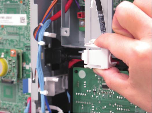
![Do not directly touch the speaker [A] of the FAX](/docs-images/73/68938287/images/59-5.jpg "Unit. Be sure not to damage the speaker [A].")
59 Installation(Super G3 FAX Board-AU1) Remove the packing tape and other materials and Install the Fax Unit. CAUTION: When installing the FAX Unit, be careful not to trap the 2 Cables of the FAX Unit. Do not directly touch the speaker [A] of the FAX Unit. Be sure not to damage the speaker [A]. [A] 3 Use the screws removed in step 4 of "Removing the Reader Connecting Plate". M3x6 4 2x 2x 54


60 Installation(Super G3 FAX Board-AU1) 6 9 8x 7 1 Installing the Covers 55
 2x Store the")
61 Installation(Super G3 FAX Board-AU1) 2x Store the removed Face Cover in the Tray Guide in step

 Procedure after Work In the case of less than")
62 5 Store the Face Cover removed in step 2 in the Tray Guide. The storage locations differ depending on the number of Face Covers ("Less than 4 Face Covers" or "4 Face Covers"). Be sure to store the removed Face Covers as shown below Installation(Super G3 FAX Board-AU1) Procedure after Work In the case of less than four In the case of four 6 57
63 Installation(Super G3 FAX Board-AU1) The following work is required only when installing the Super G3 FAX Board at the same time. Affix the following FAX Approval Label. <For USA and Taiwan> This step is only for Europe. Do not connect the Telephone Cord (2 contact type) with the PTT Plug. Connect the PTT Plug matched the field or area to the PTT Cable (6 contact type). <For Europe> 58


64 Installation(Super G3 FAX Board-AU1) Connect the end of the PTT Cable or Telephone Cord to the modular jack on the Host machine, and connect the other end to the modular jack on the wall. Turn ON the main power switch. CAUTION: If the machine does not recognize this equipment, unplug and then plug the power plug after turning OFF the main power switch, or turn OFF the main power switch and then turn it ON within 20 seconds. To avoid this symptom, unplug the power plug or turn the breaker OFF when installing. When a message prompting to turn OFF and then ON the main power appears, turn OFF and then ON the main power switch. CAUTION: When using the "EXT" modular terminal, use a flatblade screwdriver, etc. to remove the Modular Spacer located in the modular terminal area. Keep the removed Modular Spacer. Do not insert a screwdriver, etc. into the modular terminal. 5 Connect the Power Plug to the outlet. 59
65 6. Installation(Super G3 FAX Board-AU1) Operation Setting Type Settings Select the country/region of the FAX Board in Service Mode (Level 1): FAX > Type > TYPE This setting performs the parameter settings to match the communication specification of the country/region. 1. Switch the control panel display to [Fax] display. 2. Send the test document from this machine to another machine that can handle the communication test to check that this machine can send the data correctly. 3. Send the test document from the target to this machine to check if the machine can receive the document properly. 1. Set the TYPE of country/region to install this machine, and then press OK. Service Mode (Level 1) > FAX > Type > TYPE 2. Confirm that service mode (level 1) parameter below is "0". In the case, parameter is "1", change to "0". COPIER > OPTION > DSPLY-SW > SDTM-DSP Change the parameter to "0" to hide [Settings/ Registration] > [Preferences] > [Timer/Energy Settings] > [Auto Shutdown Time] and disable the auto shut down. 3. Turn OFF/ON the main power switch to enable this setting. Basic Setting When "System Manager Information Settings" is set, be sure to follow the direction of user administrator in order to log in as an administrator. In this section, make only minimum settings required for FAX communication. 1. Set the user telephone number. [Settings/Registration] > [Function Settings] > [Send] > [Fax Settings] > [Set Line] > [Line 1] > [Register User Telephone No] > Enter the fax number > [OK] 2. Set Type of telephone line. [Settings/Registration] > [Function Settings] > [Send] > [Fax Settings] > [Set Line] > [Line 1] > [Select Line Type] > Select the line type to connect > [OK] 3. Turn OFF/ON the main power switch after setting the user telephone numbers and the type of telephone line. Fax communication test Perform the communication test to check if FAX function works Correctly. 60
66 7 Installation(Super G3 2nd Line Fax Board-AU1) How to Check the Installation Procedure...62 Pre-checks Installation Procedure Checking the Operation... 76
67 How to Check the Installation Procedure Symbols The frequently-performed operations are described with symbols in this procedure. Screw 7. Installation(Super G3 2nd Line Fax Board-AU1) Packaged Item Unused Parts Install Remove Tighten Loosen Harness (Common for Guides and Clamps) Connector Power Cord Install Remove Connect Disconnect Connect Disconnect Power ON OFF Check the sound Check visually Check Push Cleaning 62

68 7. Installation(Super G3 2nd Line Fax Board-AU1) Pre-checks Checking the Contents Points to Note at Installation When installing the Super G3 FAX Board and this equipment at the same time, be sure to install them by referring to this document after checking "Checking the Contents" of Super G3 FAX Board. CAUTION: Marked portion When tightening the screws, do not tighten them too tightly. Otherwise, there is a risk of damage and deformation of screw holes. <Included in Taiwan> M3x6 7x FAX Approval Label Only for Europe Check Item When Turning OFF the Main Power Check that the main power is OFF. 1. Turn OFF the main power switch. 2. Check that the display in the Control Panel and the lamp of the main power are turned off, and then disconnect the power plug. 6 Contact type Installation Outline Drawing 63
 1")

 When the Fax Unit is not")
69 Installation Procedure 7. Installation(Super G3 2nd Line Fax Board-AU1) 1 Remove the Covers When a Telephone Cord is connected, disconnect it. 1 2x 2x 2 2 Removing the Fax Unit (When the Fax Unit is installed) When the Fax Unit is not installed, proceed to "Installation Procedure > Installing the Fax Unit". 64


70 3 7. Installation(Super G3 2nd Line Fax Board-AU1) 6 2x 4 7 5x The removed 1 Screw will be used in step 14 of "Installing the Fax Unit". 5 65
![8 CAUTION: Do not directly touch the speaker [A] of the FAX](/docs-images/73/68938287/images/71-2.jpg "Unit. Be sure not to damage the speaker [A]. [A] 7.")


71 8 CAUTION: Do not directly touch the speaker [A] of the FAX Unit. Be sure not to damage the speaker [A]. [A] 7. Installation(Super G3 2nd Line Fax Board-AU1) 1 Installing the Fax Unit Remove the packing tape if any. 2x The removed FAX Frame and 2 Screws will be used in step 11. 2x 2 The removed 2 Screws will be used in step 12 of "Installing the Fax Unit". 66


72 3 7. Installation(Super G3 2nd Line Fax Board-AU1) 6 M3x6 2x 4 5 3x 67


73 7 7. Installation(Super G3 2nd Line Fax Board-AU1) 9 Secure the included in [A] Cable in place using the Wire Saddle. 3x [A] [A] 8 10 M3x6 5x 68


74 11 7. Installation(Super G3 2nd Line Fax Board-AU1) 12 CAUTION: Installing the Plate Be sure to install the FAX Frame in an orientation appropriate for the country or region where the machine is installed. Use the screws removed in step 8 of "Removing the Fax Unit (When the Fax Unit is installed)". When installing the Super G3 Fax Board at the same time, be sure to use the screws included with the Super G3 Fax Board. <EU> <Excluding EU> CAUTION: When installing the FAX Unit, be careful not to trap the 2 Cables of the FAX Unit. Do not directly touch the speaker [A] of the FAX Unit. Be sure not to damage the speaker [A]. [A] Use the screws and the FAX Frame removed in step 1. 2x 2x 69


75 13 7. Installation(Super G3 2nd Line Fax Board-AU1) Use the screws removed in step 4 of "Removing the Fax Unit (When the Fax Unit is installed)" x 70
 1 Installing the Covers")

76 19 Open the Wire Saddle if it is closed. 7. Installation(Super G3 2nd Line Fax Board-AU1) 1 Installing the Covers 20 2 When installing the Super G3 FAX Board (1-Line) at the same time, remove the Face Cover of the 1-Line. Store the removed Face Cover in the Tray Guide in step 5. 8x 71
. Be sure to store the removed Face Covers as shown below.")
77 3 7. Installation(Super G3 2nd Line Fax Board-AU1) 5 Store the Face Cover removed in step 2 in the Tray Guide. The storage locations differ depending on the number of Face Covers ("Less than 4 Face Covers" or "4 Face Covers"). Be sure to store the removed Face Covers as shown below. In the case of less than four In the case of four 2x
78 Procedure after Work 1 When installing the Super G3 FAX Board at the same time, be sure to affix an appropriate Modular Label included in the package of the Super G3 FAX Board. 7. Installation(Super G3 2nd Line Fax Board-AU1) 2 The following work is required only when installing the Super G3 FAX Board at the same time. Affix the following FAX Approval Label. <For USA and Taiwan> <For Europe> 73
.")
79 3 7. Installation(Super G3 2nd Line Fax Board-AU1) 4 This step is only for Taiwan. Affix the following FAX Approval Label. This step is only for Europe. When installing the Super G3 FAX Board at the same time, assemble it by following the same procedure. Connect the PTT Plug matched the field or area to the PTT Cable (6 contact type). CAUTION: Do not connect the Telephone Cord (2 contact type) with the PTT Plug. 74
 7 Turn ON the main power switch.")


80 5 CAUTION: When using the "EXT" modular terminal, use a flatblade screwdriver, etc. to remove the Modular Spacer located in the modular terminal area. Keep the removed Modular Spacer. Do not insert a screwdriver, etc. into the modular terminal. 7. Installation(Super G3 2nd Line Fax Board-AU1) 7 Turn ON the main power switch. CAUTION: If the machine does not recognize this equipment, unplug and then plug the power plug after turning OFF the main power switch, or turn OFF the main power switch and then turn it ON within 20 seconds. To avoid this symptom, unplug the power plug or turn the breaker OFF when installing. When a message prompting to turn OFF and then ON the main power appears, turn OFF and then ON the main power switch. 8 If a message prompting the user to update the version appears, press [Update] to automatically update the version of this equipment. Connect the end of the PTT Cable or Telephone Cord to the Modular Jack (LINE 1 and LINE 2) on the host machine, and connect the other end to the Modular Jack on the wall. If [Skip] is selected, a message prompting the user to update the version will appear every time the host machine is started. In the service mode (Level 2) shown below, it is possible to set not to display the message. COPIER > OPTION > FNC-SW > VER-CHNG 2x 6 Connect the power plug to the outlet. 75
September 18, 2012 Revision 0. Super G3 3rd/4th Line FAX Board-AE1 Service Manual
 September 18, 2012 Revision 0 Super G3 3rd/4th Line FAX Board-AE1 Service Manual 1 2 3 4 5 6 Application This manual has been issued by Canon Inc. for qualified persons to learn technical theory, installation,
fineline Service Manual ir2020/2016 Series
 Service Manual ir2020/2016 Series Jan 30 2006 Chapter 1 Introduction 1.1 System Construction...1-1 1.1.1 Pickup/ Delivery /Original Handling Accessories System Configuration (ir2020/ir2020j)...1-1 1.1.2
April 24, 2013 Revision 0. Cassette Module-AA1 Service Manual
 1 3 5 6 April, 013 Revision 0 Cassette Module-AA1 Service Manual Application This manual has been issued by Canon Inc. for qualified persons to learn technical theory, installation, maintenance, and repair
September 10, 2012 Revision 1. Remote FAX Kit-A1 Service Manual
 1 2 3 4 September 10, 2012 Revision 1 Remote FAX Kit-A1 Service Manual Application This manual has been issued by Canon Inc. for qualified persons to learn technical theory, installation, maintenance,
Information on Sage s Fax Emulator
 Information on Sage s Fax Emulator Renshou Dai June 3, 2004 1 Introduction Sage s Fax Emulator (SFE) is a test feature that emulates both a realistic FAX transmitter and a FAX receiver. By FAX transmitter,
June 22, 2010 Revision 0. Remote FAX Kit-A1 Service Manual
 1 2 3 4 June 22, 2010 Revision 0 Remote FAX Kit-A1 Service Manual 0-2 Application This manual has been issued by Canon Inc. for qualified persons to learn technical theory, installation, maintenance, and
(DRAFT) PERSONAL DIGITAL CELLULAR TELECOMMUNICATION SYSTEM ARIB STANDARD
 PERSONAL DIGITAL CELLULAR TELECOMMUNICATION SYSTEM ARIB STANDARD") (DRAFT) EGLISH TRASLATIO PERSOAL DIGITAL CELLULAR TELECOMMUICATIO SSTEM ARIB STADARD RCR STD-27 L Fascicle 3 ISSUED REVISIO A REVISIO B REVISIO C REVISIO D REVISIO E REVISIO F REVISIO G REVISIO H REVISIO
(DRAFT) EGLISH TRASLATIO PERSOAL DIGITAL CELLULAR TELECOMMUICATIO SSTEM ARIB STADARD RCR STD-27 L Fascicle 3 ISSUED REVISIO A REVISIO B REVISIO C REVISIO D REVISIO E REVISIO F REVISIO G REVISIO H REVISIO
MX880 series Service Manual
 MX880 series Service Manual (MX882 / MX883 / MX884 / MX885 / MX886 / MX888) Revision 0 QY8-13DF-000 COPYRIGHT 2011 CANON INC. CANON MX880 series 012011 XX 0.00-0 Scope This manual has been issued by Canon
Legal Notes. Regarding Trademarks KYOCERA Document Solutions Inc.
 Legal Notes Unauthorized reproduction of all or part of this guide is prohibited. The information in this guide is subject to change without notice. We cannot be held liable for any problems arising from
Advanced User s Guide
 Advanced User s Guide MFC-J6920DW Version 0 USA/CAN User's Guides and where do I find them? Which Guide? What's in it? Where is it? Product Safety Guide Quick Setup Guide Basic User s Guide Advanced User
ADVANCED USER S GUIDE
 ADVANCED USER S GUIDE MFC-7360 MFC-7360N MFC-7460DN MFC-7470D MFC-7860DW Not all models are available in all countries. Version A SAF/GLF User's Guides and where do I find it? Which manual? What's in it?
ADVANCED USER S GUIDE
 ADVANCED USER S GUIDE MFC-J6910DW Version 0 USA/CAN User's Guides and where do I find it? Which manual? What's in it? Where is it? Safety and Legal Quick Setup Guide Basic User's Guide Advanced User's
V.8/V.34 Training Manual
 V.8/V.34 Training Manual March 31, 1998 Subject to change TABL OF CONTNTS 1. OVRVIW... 1-1 1.1 NW RCOMMNDATIONS... 1-1 1.2 PRINCIPAL CHARACTRISTICS... 1-1 1.3 PHASS OF TH V.34 PROCDUR... 1-2 1.3.1 BASIC
ADVANCED USER S GUIDE
 ADVANCED USER S GUIDE MFC-J615W MFC-J630W Version 0 USA/CAN User's Guides and where do I find it? Which manual? What's in it? Where is it? Safety and Legal Quick Setup Guide Basic User's Guide Advanced
ADVANCED USER S GUIDE
 ADVANCED USER S GUIDE MFC-J280W MFC-J625DW Version 0 USA/CAN User's Guides and where do I find it? Which manual? What's in it? Where is it? Product Safety Guide Quick Setup Guide Basic User's Guide Advanced
Advanced User s Guide
 Advanced User s Guide FAX-2840 FAX-2950 Not all models are available in all countries. Version 0 SAF/GLF User s Guides and where do I find them? Which Guide? What s in it? Where is it? Product Safety Guide
ITU-T T.30 TELECOMMUNICATION STANDARDIZATION SECTOR OF ITU
 INTERNATIONAL TELECOMMUNICATION UNION ITU-T T.30 TELECOMMUNICATION STANDARDIZATION SECTOR OF ITU (07/96) SERIES T: TERMINAL EQUIPMENTS AND PROTOCOLS FOR TELEMATIC SERVICES Procedures for document facsimile
User s Guide [Facsimile]
![User s Guide [Facsimile]](/thumbs/76/73672644.jpg "User s Guide [Facsimile]") User s Guide [Facsimile] Thank You Thank you for purchasing a bizhub C35. You have made an excellent choice. This User s Guide describes operating procedures and precautions for the use of the Fax functions.
User s Guide [Facsimile] Thank You Thank you for purchasing a bizhub C35. You have made an excellent choice. This User s Guide describes operating procedures and precautions for the use of the Fax functions.
Advanced User s Guide
 Advanced User s Guide MFC-9140CDN MFC-9330CDW MFC-9340CDW Not all models are available in all countries. Version 0 ARL/ASA/NZ User s Guides and where do I find them? Which Guide? What s in it? Where is
ADVANCED USER S GUIDE
 ADVANCED USER S GUIDE MFC-J5910DW Version 0 USA/CAN User's Guides and where to find them? Which manual? What's in it? Where is it? Product Safety Guide Quick Setup Guide Basic User's Guide Advanced User's
This amendment A1 modifies the European Telecommunication Standard ETS (1992) Terminal Equipment (TE); Group 3 facsimile equipment ETSI
 Terminal Equipment (TE); Group 3 facsimile equipment ETSI") AMENDMENT ETS 300 242/A1 September 1994 Source: ETSI TC-TE Reference: RE/TE-02020 ICS: 33.020, 33.040.40 Key words: Facsimile, group 3, ECM mode This amendment A1 modifies the European Telecommunication
AMENDMENT ETS 300 242/A1 September 1994 Source: ETSI TC-TE Reference: RE/TE-02020 ICS: 33.020, 33.040.40 Key words: Facsimile, group 3, ECM mode This amendment A1 modifies the European Telecommunication
SERVICE MANUAL FIELD SERVICE. magicolor 4690MF
 SERVICE MANUAL FIELD SERVICE 2008.05 Ver. 1.0 FIELD SERVICE TOTAL CONTENTS SAFETY AND IMPORTANT WARNING ITEMS...S-1 IMPORTANT NOTICE...S-1 DESCRIPTION ITEMS FOR DANGER, WARNING AND CAUTION...S-1 SAFETY
February 27, 2012 Revision 0. Cassette Feeding Unit-AF1 Service Manual
 February 7, 0 Revision 0 Cassette Feeding Unit-AF Service Manual 4 Application This manual has been issued by Canon Inc. for qualified persons to learn technical theory, installation, maintenance, and
FAX Option Type Facsimile Reference (option) <Basic Features> Operating Instructions
 <Basic Features> Operating Instructions") ZCHH010N.eps FAX Option Type 4000 Operating Instructions Facsimile Reference (option) Read this manual carefully before you use this product and keep it handy for future reference. For
ZCHH010N.eps FAX Option Type 4000 Operating Instructions Facsimile Reference (option) Read this manual carefully before you use this product and keep it handy for future reference. For
ADVANCED USER S GUIDE
 ADVANCED USER S GUIDE MFC-J825DW MFC-J835DW Version A USA/CAN User's Guides and where do I find it? Which manual? What's in it? Where is it? Product Safety Guide Quick Setup Guide Basic User's Guide Advanced
ADVANCED USER S GUIDE
 ADVANCED USER S GUIDE MFC-9460CDN MFC-9465CDN Not all models are available in all countries. Version 0 UK/IRE User's Guides and where do I find it? Which manual? What's in it? Where is it? Safety and Legal
PIXMA MP830 SERVICE MANUAL
 PIXMA MP830 SERVICE MANUAL Revision 0 QY8-3AN-000 COPYRIGHT 2006 CANON INC. CANON PIXMA MP830 022006 XX 0.00-0 Scope This manual has been issued by Canon Inc., to provide the service technicians of this
document communication system FO-DC535 FO-DC635
 document communication system FO-DC535 fast, flexible performance for all your business needs With the Sharp FO-DC535/DC635 Super G3 Document Communication Systems, you ll get everything you need in a
Advanced User s Guide
 Advanced User s Guide MFC-L8600CDW MFC-L8650CDW MFC-L8850CDW MFC-L9550CDW DCP-L8400CDN DCP-L8450CDW Not all models are available in all countries. Version 0 ARL/ASA/NZ User s Guides and where do I find
Product Parts Front view... 2 Rear view... 2 Inside the product... 3 Scanner parts... 3 Control panel... 4
 Table of Contents Product Parts Front view................................................................. 2 Rear view.................................................................. 2 Inside the product...........................................................
Power Supply Information... 3 Connecting a Phone or Answering Machine... 3 Setting Up Your Fax Features... 4
 Fax Guide English Setting Up Your Fax Power Supply Information... 3 Connecting a Phone or Answering Machine... 3 Setting Up Your Fax Features... 4 Faxing Photos or Documents Handling Originals... 10 Handling
SD-40 P/A Keypad Analog Door Phone Door Access Control with Analog Telephony Interface. Door Access Control with analog telephony interface
 SD-40 P/A Keypad Analog Door Phone Door Access Control with Analog Telephony Interface Release 1.18_U1_3 June 2016 Phones Analog Door Door Access Control with analog telephony interface Installation and
Support for UFR II LT and PCL 5e/6 > Standard Color Send > Standard 256MB RAM (up to 1,500 pages***) > Up to 500 one-touch/coded dial buttons
 > Up to 500 one-touch/coded dial buttons") Scan,Copy &FaxSolutions LaserClass 830i/810 Facsimile Workgroup Solutions L a s e r C l a s s 8 0 0 S e r i e s Go Beyond Fax Canon takes the traditional office facsimile to the next level with the LASER
Scan,Copy &FaxSolutions LaserClass 830i/810 Facsimile Workgroup Solutions L a s e r C l a s s 8 0 0 S e r i e s Go Beyond Fax Canon takes the traditional office facsimile to the next level with the LASER
Handling Originals Handling Paper Sending Faxes Receiving Faxes Selecting Send/Receive Settings Printing Reports...
 Fax Guide English Setting Up Your Fax Introducing FAX Utility (Windows Only)... 3 Power Supply Information... 3 Connecting a Phone or Answering Machine... 3 Checking Your Fax Connection... 4 Setting Up
FAX Option Type Facsimile Reference <Advanced Features> Operating Instructions
 FAX Option Type 3045 Operating Instructions Facsimile Reference 1 2 3 4 5 6 7 8 9 10 11 Transmission Mode Checking and Canceling Transmission Files Communication Information Other Transmission
rview Produc Ove imil s ac ure at Operating Instructions c F (For Advanced Operations) Facsimile Transceiver ure csimile at Fe Advanced
 Facsimile Transceiver ure csimile at Fe Advanced") Problem Solving Setting Your Machine Network Scanner Feature Basic Facsimile Feature Advanced Facsimile Feature Appendix Advanced Internet Fax Feature Internet Fax/ Email Features Copy Feature Product
Problem Solving Setting Your Machine Network Scanner Feature Basic Facsimile Feature Advanced Facsimile Feature Appendix Advanced Internet Fax Feature Internet Fax/ Email Features Copy Feature Product
Second Phone Line Kit Manual for sx1480/fx2080
 Second Phone Line Kit Manual for sx1480/fx2080 Contents Regulatory information...i Users in United States of America... i FCC Part 15... ii Users in Canada...iii Canadian ICES-003...iii Setting up...1-1
NEW plain paper fax machines.
 NEW plain paper fax machines. Perfect for your home - FAX-1360 - FAX-1460 - FAX-1560 FAX-1560 For quick, easy-to-use faxing and copying you need one of the new range of plain paper fax machines from Brother.
Use the last 4 digits of the error code to match the appropriate code shown below to determine error cause.
 FAX ERROR CODES Use the last 4 digits of the error code to match the appropriate code shown below to determine error cause. Line infoex defines error. ## 0000 [fax-0] type=normal context=info code=0 apiref=bt_status_ok
ASAP 104. Installation and Reference Guide. Register Online at
 ASAP 104 Installation and Reference Guide Customer Service U.S.: 1-800-288-6794 E-mail: techsupport@commandcommunications.com Register Online at www.commandcommunications.com Table of Contents Introduction
Fax Option Type M3/M4 Machine Code: D163/D167 Field Service Manual
 Fax Option Type M3/M4 Machine Code: D163/D167 Field Service Manual May, 2014 Subject to change Revision Lists (V2.00) Revision Date: 22.05.2014 Before Table of Contents Section Item Note Important Safety
ATL20 ATL30 Automatic transfer switch controller
 I 194 GB 07 07 ATL20 ATL30 Automatic transfer switch controller REMOTE CONTROL SOFTWARE MANUAL Summary Introduction... 2 Minimum resources of the PC... 2 Installation... 2 Activation of the PC-ATL connection...
304 Chapter 2 Solve problems ENWW
 Manage Supplies menu To display: At the product control panel, select the Administration menu, and then select the Manage Supplies menu. In the following table, asterisks (*) indicate the factory default
Quick Reference Guide
 Facsimile Quick Reference Guide Model No. KX-PW320DL KX-PW320DW Main unit: Portable handset: KX-PW320 KX-FKN526 KX-PW320DL Thank you for purchasing a Panasonic product. Table of Contents Finding the controls
XEROX. WorkCentre Pro 555/575 Advanced Features Guide 708P84302
 XEROX WorkCentre Pro 555/575 Advanced Features Guide 708P84302 Xerox Limited, Global knowledge and Language Services, Enterprise Centre, Bessemer Road, WELWYN GARDEN CITY, AL7 1HE United Kingdom 2000 by
SERVICE MANUAL FIELD SERVICE
 SERVICE MANUAL FIELD SERVICE 2008.09 Ver. 1.0 FIELD SERVICE TOTAL CONTENTS SAFETY AND IMPORTANT WARNING ITEMS...S-1 IMPORTANT NOTICE...S-1 DESCRIPTION ITEMS FOR DANGER, WARNING AND CAUTION...S-1 SAFETY
Basic Operation Guide
 Basic Operation Guide For information about machine setup and software installation, see the Starter Guide. This guide describes the basic use of the machine. Read this guide after finishing the machine
Installation instructions for Aluminium Pantel, Pancode and Pancam C & T Telephone door access control units
 Installation instructions for Aluminium Pantel, Pancode and Pancam C & T Telephone door access control units This manual and the information it contains may not, in whole or in part, be reproduced, copied,
MF9500. Operation Manual for network scanner
 MF9500 Operation Manual for network scanner 00008-0 S INTRODUCTION The optional Network Scanner Expansion Kit (SG-NS) enables the machine to be used as a network scanner. Page of the manual that accompanies
FACSIMILE SYSTEMS. 730i. 720i LASER CLASS LASER CLASS LASER CLASS 710
 INTERNET FACSIMILE SYSTEMS LASER CLASS 730i LASER CLASS 720i LASER CLASS 710 A New Standard in Facsimile Communications Fax machines are perhaps the most reliable, commonplace business tools next to the
Powerful Performance. Advanced Functionality. Optimized Productivity. with STANDARD DUPLEX PRINTING AR-M208N
 NOW with STANDARD DUPLEX PRINTING Powerful Performance. Advanced Functionality. Optimized Productivity. C O P Y P R I N T S C A N F A X AR-M208N AR-M208N highlights 20 ppm copy/print speed 1,100-sheet
COLOR BUBBLE JET PRINTER FAX SCANNER COPIER C530/C560
 COLOR BUBBLE JET PRINTER FAX SCANNER COPIER C530/C560 Stand-alone Fax Manual Copyright Disclaimer This manual is copyrighted by Canon Computer Systems, Inc. (CCSI) with all rights reserved. Under the copyright
August 3, 2009 Revision 0. Document Insertion Unit-H1 Service Manual
 1 2 3 4 5 6 August 3, 2009 Revision 0 Document Insertion Unit-H1 Service Manual 0 Application This manual has been issued by Canon Inc. for qualified persons to learn technical theory, installation, maintenance,
APPLICATION NOTE. N2 Dial Application. Using N2 Dial...3. Introduction...3. Key Concepts...4
 FANs 637.5, 1637.5 N2 Dial Section Issue Date 0400 APPLICATION NOTE N2 Dial Application Using N2 Dial...3 Introduction...3 Key Concepts...4 N2 Dial Configuration... 4 Downloading with N2 Dial...*6 Dial-in
Plain Paper Laser Fax UF-7300
 Plain Paper Laser Fax UF-7300 Totally reliable performance in an easy to use desktop design Re-engineered to deliver increased paper capacity and expanded functionality in a compact desktop design, the
X644e and X646e. Menus and Messages Guide. January 2006
 X644e and X646e Menus and Messages Guide January 2006 www.lexmark.com Lexmark and Lexmark with diamond design are trademarks of Lexmark International, Inc., registered in the United States and/or other
6(59,&( 0$18$/ EPSON Stylus Photo Color Inkjet Printer SEIJ98007
 6(59,&( 0$18$/ Color Inkjet Printer EPSON Stylus Photo 1200 SEIJ98007 Notice All rights reserved. No part of this manual may be reproduced, stored in a retrieval system, or transmitted in any form or by
RS K Ext Modem. User Manual
 RS-232 56K Ext Modem User Manual Content 1. Introduction... 2 2. Features... 3 3. Installation... 4 3.2.1 Installation Procedures for Windows 64 bits (XP/Win7/Vista)... 6 3.2.2 Installation Procedures
KX-MB2120 FAX PANASONIC KX-MB2120 multifunctional printer
 KX-MB2120 FAX PANASONIC KX-MB2120 multifunctional printer High Productivity, Small Size. 26ppm printing/26 cpm copying (A4) 24ppm quick duplexing (A4) 600dpi print resolution Up to 19200 interpolated dpi
MODEL : SLK-TL100 Receipt Printer User s Manual
 J. STEPHEN Lab., Ltd. 28-6, Gajangsaneopdong-ro, Osan-si, Gyeongi-do, 447-210, Korea TEL : +82-31-459-8200 FAX : +82-31-459-8880 www.miniprinter.com MODEL : SLK-TL100 Receipt Printer User s Manual TL100
User s Guide [Network Scan/Fax/Network Fax Operations]
![User s Guide [Network Scan/Fax/Network Fax Operations]](/thumbs/72/66923084.jpg "User s Guide [Network Scan/Fax/Network Fax Operations]") User s Guide [Network Scan/Fax/Network Fax Operations] Introduction Thank you for purchasing this machine. This User s Guide describes the operating instructions, precautions for proper operation, and
User s Guide [Network Scan/Fax/Network Fax Operations] Introduction Thank you for purchasing this machine. This User s Guide describes the operating instructions, precautions for proper operation, and
PURPOSE OF THE ADMINISTRATOR SETTINGS
 Contents page PURPOSE OF THE ADMINISTRATOR SETTINGS...1 ADMINISTRATOR SETTINGS LIST...3 USING THE ADMINISTRATOR SETTINGS...4 GENERAL SETTINGS...7 COPY SETTINGS...16 DOCUMENT FILING SETTINGS...18 TO THE
MODEL : SLK-T12EB Receipt Printer User s Manual
 J. STEPHEN Lab., Ltd. 28-6, Gajangsaneopdong-ro, Osan-si, Gyeonggi-do, 447-210 Republic of Korea TEL : +82-31-8077-5000 FAX : +82-31-459-8880 www.miniprinter.com MODEL : SLK-T12EB Receipt Printer User
SERVICE MANUAL MODEL SSW-521-D2-ADA
 SSW-521-D2-ADA-SPK1.07UNVLr3-ADA-ISSUE4.0 SERVICE MANUAL FOR MODEL SSW-521-D2-ADA STAINLESS STEEL HANDS FREE WALL TELEPHONE WITH OPTIONAL ADA FEATURE AND OPTIONAL SECOND-NUMBER AUTO-DIAL FEATURE EQUIPPED
Aristel Networks Pty Ltd. All Round Cabling Solutions NEOS3003-3G01. Operating Manual * NEOS G01
 Aristel Networks Pty Ltd All Round Cabling Solutions NEOS3003-3G01 Operating Manual * NEOS 3003-3G01 Supports 3G/UMTS 800/850/900/1900/2100 MHz bands Telstra-Vodafone-Optus supported in all areas. * Model:
Muratec F-160. Finally. A machine that works like you do. Fast. Cost-conscious. Reliable. Customizable. See what the F-160 can do for your office.
 Muratec F-160 33.6 Kbps modem, JBIG compression 2.8-second transmission speeds 8-page-per-minute laser printing Muratec FaxRISC processor QuadAccess capabilities Muratec's ImageLSI technology Finally.
MODEL : LK-TL200 Receipt Printer User s Manual
 SEWOO TECH CO.,LTD. 28-6, Gajangsaneopdong-ro, Osan-si, Gyeongi-do, 447-210, Korea TEL : +82-31-459-8200 FAX : +82-31-459-8880 www.miniprinter.com MODEL : LK-TL200 Receipt Printer User s Manual TL200 Rev.
How to read this manual...ii. Symbols... ii Key descriptions... ii. Regulatory information... iii
 Contents How to read this manual...ii Symbols... ii Key descriptions... ii Regulatory information... iii Users in United States of America... iii Users in Canada...v Setting up...1-1 Connecting the telephone
document communication systems
 document communication systems Transform your business and maximize the communication of your ideas. Communication transformed. Business communication is a critical component of success. As the power and
Operation Guide <Functions Edition> Click on the button to jump to the desired section.
 Operation Guide Click on the button to jump to the desired section. Using the Scanner Function Sending Scanned Image Data to Your Computer Sending Scanned Image Data by Email Using
EAR K. Installation and Programming. Manual
 EAR 2000 4K Installation and Programming Manual EAR 2000 4K Installation and Programming Manual Release 1 Version 3 June 2011 NOTICE This publication refers to the EAR 2000, Release 3. Additional copies
Scanner Reference. Operating Instructions
 Operating Instructions Scanner Reference 1 2 3 4 5 6 7 Sending Scan Files by E-mail Sending Scan Files to Folders Storing Files Using the Scanner Function Delivering Scan Files Scanning Originals with
IP FAX Expansion Kit. User's Guide ENG
 IP FAX Expansion Kit User's Guide Please read this guide before operating this product. After you finish reading this guide, store it in a safe place for future reference. ENG How This Manual Is Organized
INSTRUCTION MANUAL SEPARATION KIT RMK-4
 INSTRUCTION MANUAL SEPARATION KIT RMK- FOREWORD Thank you for purchasing the RMK- separation kit. The RMK- allows you to connect the additional CONTROL HEAD to the IC-F95HT to enable dual-head operation.
91928_iR1025Bro.qxd:91928_iR1025Bro 10/25/08 3:30 PM Page 3 Workgroup Solutions
 Workgroup Solutions Workgroup Solutions REDEFINING WORKGROUP EFFICIENCY Advanced multifunction technology designed with small businesses and workgroups in mind. Just because your needs are small in scale
Mac Printer Driver User's Manual
 Mac Printer Driver User's Manual Overview Descriptions of the TM-T0 Software Installer features. Installation Descriptions of install and uninstall. Using the Printer Driver Descriptions of simple printing
User Guide. What You Can Do with This Machine. Getting Started. Copy. Fax. Print. Scan. Document Server. Web Image Monitor. Adding Paper and Toner
 User Guide What You Can Do with This Machine Getting Started Copy Fax Print Scan Document Server Web Image Monitor Adding Paper and Toner Troubleshooting Information for This Machine For safe and correct
DIGITAL FULL COLOUR MULTIFUNCTIONAL SYSTEM
 DIGITAL FULL COLOUR MULTIFUNCTIONAL SYSTEM Troubleshooting MODEL: MX-2300G MX-2700G MX-2300N MX-2700N In the unlikely event of you experiencing a problem with this product, please refer to this manual
3700 SERIES USER MANUAL
 SAFETY GUIDE This manual contains the precautions necessary to ensure your personal safety as well as for protection for the products and the connected equipment. These precautions are highlighted with
March 8, 2010 Revision 0. Cassette Feeding Unit-AE1 Service Manual
 5 March 8, 00 Revision 0 Cassette Feeding Unit-AE Service Manual F-0- Safety Precautions Contents Notes Before Servicing------------------------------------------------------0- Specifications Specification---------------------------------------------------------------------
User Manual for the AN208
 Aristel Networks User Manual for the AN208 2 Line / 9 Handset Telephone System Aristel Networks Pty Ltd Unit 1, 25 Howleys Road Notting Hill. Victoria. 3168 Telephone: 03 8542 2300 Facsimile: 03 9544 3299
Reminder Text highlighted in this manner indicates operation precautions. Carefully read and observe this type of information.
 Introduction Thank you for choosing this machine. The bizhub 50/4/6 User s Guide [Enlarge Display Operations] contains details on the operation of the various functions available in the Enlarge Display
Network Multi-PDL Printer kit-c1
 Network Multi-PDL Printer kit-c1 REVISION 0 APR. 2001 FY8-13HE-000 COPYRIGHT 2001 CANON INC. 200 CANON NW Multi-PDL P. kit-c1 REV.0 APR. 2001 PRINTED IN U.S.A. Application This manual has been issued by
Canon ir1600 / ir2000. Details
 E000 E001 E002 E003 E004 Error Codes Canon ir1600 / ir2000 Details The main thermistor reading does not reach 40 o C 14 sec after the fixing heater goes ON (fixing low temperature error) The main thermistor
MODEL : SLK-TS400EB. Receipt Printer User s Manual. TS400EB Rev. B 07/16. All specifications are subject to change without notice
 MODEL : SLK-TS400EB Receipt Printer User s Manual TS400EB Rev. B 07/16 All specifications are subject to change without notice Table of Contents 1. Parts Identifications 1. Parts Identifications 3 2.
HP LaserJet 3050/3052/3055 All-in-One Service Manual
 HP LaserJet 3050/3052/3055 All-in-One Service Manual HP LaserJet 3050/3052/3055 All-in-One Service Manual Copyright and License 2006 Copyright Hewlett-Packard Development Company, LP Reproduction, adaptation,
i-sensys MF4320d Up to 1200 x 600 dpi with Automatic Image Refinement % in 1% increments 250-sheet tray 1-sheet manual feed slot
 Machine type Available functions Printer Print speed Printing method Print quality i-sensys MF4320d Mono Laser All-in-One Print, Copy and Scan Up to 22 ppm (A4) Monochrome laser beam printing Up to 1200
Owner s Manual DA-300USB D/A CONVERTER. Appendix. Contents. You can print more than one page of a PDF onto a single sheet of paper.
 DA-300USB D/A CONVERTER Owner s Manual You can print more than one page of a PDF onto a single sheet of paper. Front panel Display Rear panel Contents Accessories 3 Features 4 High quality sound 4 High
You have accessed an older version of a Paradyne product document.
 You have accessed an older version of a Paradyne product document. Paradyne is no longer a subsidiary of AT&T. Any reference to AT&T Paradyne is amended to read Paradyne Corporation. Paradyne 6700-A2-GB41-10
MODEL : AP-8220 U Receipt Printer User s Manual
 MODEL : AP-8220 U Receipt Printer User s Manual AP-8220 U Rev.A 10/14 All specifications are subject to change without notice Table of Contents 1. Parts Identifications 1. Parts Identifications 3 2. Setting
N-8000 SERIES IP INTERCOM SYSTEM
 N-8000 SERIES IP INTERCOM SYSTEM Cutting-edge TOA technology for greater versatility and improved sound quality IP Network-Compatible Intercom System with Packet Audio Technology The TOA N-8000 Packet
Instruction Handbook DC Scan (F)
") Instruction Handbook DC 2116 2120 2125 Scan (F) Digital Multifunctional System This Operation Guide mentions that DC 2116 is a 16 ppm (prints per minute) machine, DC 2120 is a 20 ppm (prints per minute)
Instruction Handbook DC 2116 2120 2125 Scan (F) Digital Multifunctional System This Operation Guide mentions that DC 2116 is a 16 ppm (prints per minute) machine, DC 2120 is a 20 ppm (prints per minute)
REDEFINING WORKGROUP EFFICIENCY Advanced multifunction technology designed with small businesses and workgroups in mind.
 Workgroup Solutions Wo r kg r o u p S o lu t i o ns REDEFINING WORKGROUP EFFICIENCY Advanced multifunction technology designed with small businesses and workgroups in mind. Just because your needs are
2.1 Overview of Features and Connection Modes Scanning Features Product Specifications
 Network Scanner Contents 1 Introduction 1.1 Welcome... 1-2 1.1.1 Composition of User's Guide... 1-2 1.1.2 User's Guide... 1-3 1.2 Conventions used in this manual... 1-4 1.2.1 Symbols used in this manual...
pagepro 5650EN/4650EN
 SERVICE MANUAL FIELD SERVI pagepro 5650EN/4650EN 2007.11 Ver. 1.0 FIELD SERVICE TOTAL CONTENTS SAFETY AND IMPORTANT WARNING ITEMS...S-1 IMPORTANT NOTICE...S-1 DESCRIPTION ITEMS FOR DANGER, WARNING AND
Low Speed Modems for Dial and Leased Circuits 2400E (Standalone) 2400R (Rackmount)
 2400R (Rackmount)") Low Speed Modems for Dial and Leased Circuits 2400E-030-4 (Standalone) 2400R-030-4 (Rackmount) QUALITY COMMUNICATIONS PRODUCTS Made in the U.S.A. 11-1010-002 INTRODUCTION The Data Connect ST2400E-2 and
Low Speed Modems for Dial and Leased Circuits 2400E-030-4 (Standalone) 2400R-030-4 (Rackmount) QUALITY COMMUNICATIONS PRODUCTS Made in the U.S.A. 11-1010-002 INTRODUCTION The Data Connect ST2400E-2 and
KX-HTS824 KX-HTS32. Feature Manual. Hybrid IP-PBX. Model No.
 Feature Manual Hybrid IP-PBX Model No. KX-HTS824 KX-HTS32 Thank you for purchasing this Panasonic product. Please read this manual carefully before using this product and save this manual for future use.
Scanner Reference. Operating Instructions
 Operating Instructions Scanner Reference 1 2 3 4 5 6 7 Sending Scan Files by E-mail Sending Scan Files to Folders Storing Files Using the Scanner Function Delivering Scan Files Scanning Originals with
R7X CONFIGURATOR. (model: R7CON) Users Manual , Minamitsumori, Nishinari-ku, Osaka JAPAN Tel: Fax:
 Users Manual , Minamitsumori, Nishinari-ku, Osaka JAPAN Tel: Fax:") R7X CONFIGURATOR (model: R7CON) Users Manual 5-2-55, Minamitsumori, Nishinari-ku, Osaka 557-0063 JAPAN Tel: +81-6-6659-8201 Fax: +81-6-6659-8510 http://www.m-system.co.jp/ E-mail: info@m-system.co.jp R7CON
R7X CONFIGURATOR (model: R7CON) Users Manual 5-2-55, Minamitsumori, Nishinari-ku, Osaka 557-0063 JAPAN Tel: +81-6-6659-8201 Fax: +81-6-6659-8510 http://www.m-system.co.jp/ E-mail: info@m-system.co.jp R7CON
Printing for Professionals
 Océ cm5/ cm5 Printing for Professionals User s Guide Enlarge Display Operations Introduction Thank you for choosing this machine. The Océ cm5/cm5 User s Guide [Enlarge Display Operations] contains details