MANUAL PLC1.01 BOARD
|
|
|
- Rudolph Owens
- 5 years ago
- Views:
Transcription
1
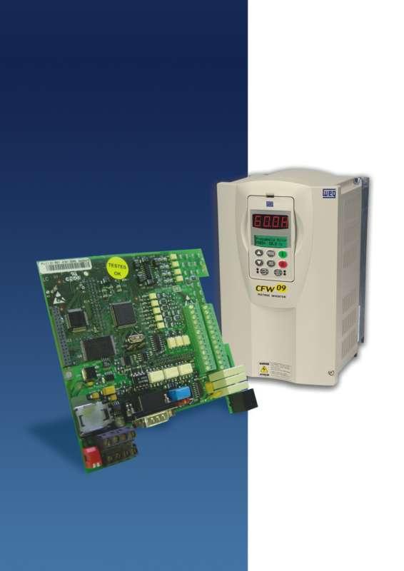
2 MANUAL PLC1.01 BOARD PROGRAMMABLE IN LADDER LANGUAGE BY WLP SOFTWARE 10/2005 PLC1 Software: V1.7X E/3
3 Summary of Revisions The table below describes all revisions made to this manual. Revision Description Section 1 First Edition - 2 Functions related to the Online Monitoring - 3 General Review and Inclusion of CANopen - and DeviceNet protocols
4 Summary I Parameters...06 II Error messages...08 CHAPTER 1 Safety Notices 1.1 Safety notices in the manual Safety notices on the product Preliminary recommendations...10 CHAPTER 2 General Information 2.1 About this manual About the PLC General characteristics of the PLC Hardware Software...13 CHAPTER 3 Installation and configuration 3.1 Installing the plc board on the drive Configuring the jumpers Connectors description Configuring the CFW-09 to operate with PLC CHAPTER 4 Detailed parameter description Detailed parameter description... 21
5 PLC - QUCIK PARAMETER REFERENCE QUICK PARAMETER REFERENCE, FAULT MESSAGES Software: V1.7X Application: Model: Serial Number: Responsible: Date: / /. The parameter range starts from 750 up to 899, totalizing 150 parameters. The first 50 parameters are predefined by the system or are reserved parameters. The 100 remaining parameters are for general use and may be set by the user. Please find below a description of the parameters defined by the system. I. Parameters Parameter Function Adjustable Range Factory Unit Page Setting P750 PLC1 firmware version Related to the purchased board P751 Scan cycle in 100µs units 0 to x100µs 21 P752 (*) Resets the retentive markers 0 = no action 0 = no action = reset register P753 (*) Loads factory settings, 0 to if =1234 P754 Position reference (rotations) 0 to rot 21 P755 Position reference 0 to degrees / (fraction of rotation) P756 Position signal 0 = negative = positive P757 Real position (rotations) 0 to rot 21 P758 Real position (fraction of rot.) 0 to degrees / P760 Kp: proportional position gain 0 to P761 Ki: Integral position gain 0 to P762 Max. lag error 0 to degrees / P763 Disables user program if =1 0=program enable =program disable P764 (*) PLC address at netwrok 1 to P765 (*) Baud rate of RS232 1 = 1200bps 4 = 9600bps bits/second 22 2 = 2400bps 3 = 4800bps 4 = 9600bps 5 = 19200bps P766 Status of the Digital Inputs 0=resolver (SCA-05) =encoder (X8) P767 (*) Synchronou speed of the 0 to rpm 23 motor in rpm (*) IMPORTANT: to enable the system to operate according the parameter seeting, the system must be reset after one or more parameters have been changed. 6
6 PLC - QUCIK PARAMETER REFERENCE Parameter Function Adjustable Range Factory Unit Page Setting P768 (*) Encoder pulse number 0 to ppr 23 P769 (*) Encoder zero pulse position 0 to degrees / P770 CAN Protocol 0 = Disabled 0 = Disabled = CANopen 2 = DeviceNet P771 CAN Address 0 to P772 CAN Baudrate 0=1Mbit/s 0=1Mbit/s bits/second 24 1=Reserved 2=500 Kbit/s 3=250 Kbit/s 4=125 Kbit/s 5=100 Kbit/s 6=50 Kbit/s 7=20 Kbit/s 8=10 Kbit/s P773 Bus off recovery 0=Manual 0=Manual =Automatic P774 Action to be taken upon 0=Indicate the error 1-24 detection of a communication 1=Cause a fatal failure error on the device P775 CAN Status 0=Disable =Reserved 2=CAN enable 3 = Warning 4= Error pacive 5= Bus off 6 = Not Powered P776 Counter of received 0 to telegrams P777 Counter of trasmitted 0 to telegrams P778 Counter of detected erros 0 to P780 Status of the CANopen 0=Disabled network 1=Reserved 2=CANopen enabled 3=Node Guarding enabled 4=Node Guarding error P781 Status of the CANopen node 0=Not initialized =Stopped 5=Operational 127=Pre-operational P782 Status of the DeviceNet 0=Not Powered / network Not On-line 1=On-line / Not Connected 7
7 PLC - QUCIK PARAMETER REFERENCE Parameter Function Adjustable Range Factory Unit Page Setting 2=Link OK / Online and Connected 3=Connection Timeout 4=Critical Link Failure 5=Running Auto-baud P783 Status of the DeviceNet 0 = Run Master 1 = Idle P784 Number of input words 1 to P785 Number of output words 1 to II. Error Messages 8 Display Description Note E50 Lag error Fatal Error, it disables the converter. Refer to Parameter P762. E51 Error during Reset the systems and program saving try again. E52 Two or more Check the user program logic movements enabled simultaneously E53 Movement data are Perhaps some speed, acceleration not valid value, etc. was reset to zero. E54 Inverter disabled Attempt to execute some movement with disabled inverter E55 Incompatible program Check program and install it again. or out of memory limits This error also occurs when there is no program installed in the PLC (PLC powered-up first time). E56 Wrong CRC Transmit it again. E57 Shaft has not been Before an absolut movement, referenced to absolute you must set the machine movement movement to zero position. E58 Master Reference Fatal Error: after enabled initial Fault communication, between master and slave, by any cause has been disabled. E61 Bus off Bus off has been detected on the CAN bus due to a high number of transfer erros. These erros may be caused due to bus problems or due to improper installation. E65 Node Guarding Error Specific error for the CANopen communication. For further information, please, refer to the CANopen communication user s guide provided with the product CD. E66 Master in IDLE mode Specific error for the CANopen communication. For further information, please, refer to the CANopen communication user s guide provided with the product CD. E67 Timeout de Specific error for the CANopen conexões I/O communication. For further information, please, refer to the CANopen communication user s guide provided with the product CD. Note: In fatal erros, E50 and E58, the inverter is disabled and need restart.
8 CHAPTER 1 SAFETY NOTICES This Manual contains all necessary information for the correct installation and operation of the PLC1 with the CFW-09 Variable Frequency Drive. The PLC1 Manual has been written for qualified personnel with suitable training of technical qualifications to operate this type of equipment 1.1 SAFETY NOTICES IN THE MANUAL The following Safety Notices will be used in this Manual: DANGER! If the recommended Safety Instructions are not strictly observed, it can lead to serious or fatal injuries of personnel and/or equipment damage. ATTENTION! Failure to observe the recommended Safety Procedures can lead to material damage. NOTES! The content of this Manual supplies important information for the correct understanding of operation and proper performance of the equipment. 1.2 SAFETY NOTICES ON THE PRODUCT The following symbols may be attached to the product, serving as Safety Notice: High Voltages Components are sensitive to electrostatic discharge. Do not touch them without following proper grounding procedures. Mandatory connection to ground protection (PE) Shield connection to ground 9
9 CHAPTER 1 - SAFETY NOTICES 1.3 PRELIMINARY RECOMMENDATIONS DANGER! Only qualified personnel should plan or implement the installation, start-up, operation and maintenance of the CFW- 09 and associated equipment. The personnel must follow all safety instructions included in this Manual and/or defined by the local regulations. Failure to comply with these instructions may result in personnel injury and/or equipmrnt damage. NOTES! In this Manual, qualified personnel are defined as people that are trained to: 1. Install, ground, power up and operate the CFW-09, as well as the PLC1 board, according to this Manual and the local safety procedures; 2. Use the safety equipment according to the local regulations; 3. Give first aid. DANGER! Always disconnect the supply voltage before touching any electrical component inside the inverter. Many components are charged with high voltages, even after the incoming AC power supply has been disconnected or switched OFF. Wait at least 10 minutes for the total discharge of the power capacitors. Always connect the frame of the equipment to the ground (PE) at the suitable connection point. ATTENTION! All electronic boards have components that are sensitive to electrostatic discharges. Never touch any of the electrical components or connectors without following proper grounding procedures. If necessary to do so, touch the properly grounded metallic frame or use a suitable ground strap. NOTES! Read this entire Manual carefully and completely before installing or operating PLC1 board with the CFW
10 CHAPTER 2 GENERAL INFORMATION This chapter defines the contents and purpose of this manual This manual provides instructions for installation and use of the PLC1 board. Chapter 1 - Safety Notices; Chapter 2 - General Information; Chapter 3 - Instalation and configuration; Chapter 4 - Detailed Parameter description. 2.1 ABOUT THIS MANUAL This Manual provides information required for the correct use of the PLC1. As the PLC1 is very flexible, it allows many different operation modes as described in this Manual. As the PLC1 can be applied in several ways, it is impossible to describe here all application possibilities of this board. WEG does not assume any responsibility when the PLC1 is not used according to this manual. No part of this Manual may be reproduced in any form, without written consent of WEG. The communication user s guide for the PLC1 board presented in table 2.1 complements this user s guide. These user s guides are available in PDF format on the product CD and also at WEG website. The compatibility of these user s guides and the product is directly related to the product software version. Hence, pay attention to the communication user s guide identification (P/1, P/2... ) when downloading it from the WEG website. PLC1 V1.7X User s Guide Revision Serial Communication User s Guide P/3 CANopen Slave User s Guide P/2 DeviceNet Slave User s Guide P/2 WLP User s Guide P/2 Table Communication user s guide for the PLC1 board 2.2 ABOUT THE PLC1 BOARD The PLC1 board adds important PLC (Programmable Logical Controller) functions to the CFW-09, enabling the execution of complex linkage program by using the digital board inputs and outputs as well as the digital and analog inputs and outputs of the own inverter which can be accessed by the user s program. 11
11 CHAPTER 2 - GENERAL INFORMATION 2.3 GENERAL CHARACTERISTICS OF THE PLC1 Among the several available functions we can mention simple contacts and coils up to functions that uses floating point, such as sum, subtraction, multiplication, division, trigonometry, square root functions, etc. Other important functions are the PID blocks, high-pass and low-pass filters, saturation, comparison. All these functions operate with floating point. Besides the functions mentioned above, the PLC1 provides blocks for motor speed and motor position control, that is a trapezoidal-profile positioning and a S-profile positioning, speed reference generation with trapezoidal acceleration ramp, etc. (Note: when positioning functions used, the coupling of an encoder on motor shaft is required). All functions can interact with the user through the 100 programmable parameters that can be acessed directly through the inverter HMI. The texts and user units of the programmable parameters can be customized by the WLP. The new Modbus functions introduced with the Version V1.50 of the board PLC1 allow executing advanced on-line monitoring function with the Ladder program through the WLP from Version V4.00 on. ATTENTION! The CFW-09 inverter software version should be the version V2.40 or later Hardware The PLC1 board has the following hardware characteristics: 9 isolated digital inputs, bi-directional, 24Vdc; 3 digital relay output 250V x 3A; 3 digital optocoupled outputs, bi-directional, 48Vdc x 500mA; 1 isolated encoder input, with external supply between 18Vdc and 30Vdc; Encoder supply - 15Vdc x 300mA; 1 serial communication interface RS-232C (standard Protocol: MODBUS-RTU); All sizes compatible with CFW-09; User programming in Ladder language, with specific blocks for positioning and PLC functions It permits the use of digital and analog inputs/ouputs of the CFW-09, comprising 15 digital inputs, 9 digital outputs, 2 analog inputs and 2 analog outputs, accessed by the ladder. 12
12 CHAPTER 2 - GENERAL INFORMATION Software The software for the PLC1 board has the following characteristics: The Parameter Range comprises the parameter from 750 to 899, totaling 150 parameters. The 50 first parameters are predefined by the system or are reserved parameters. The other 100 remaining parameters are for general use, i. e., they may be programmed by the user and can be used for the most different functions, as contactors, timers, speed, acceleration and position references, etc; BIT and volatile WORD type Markers (initialized at zero) and retentive and volatile FLOAT type markers; The programming of the PLC board is performed via WLP Software using the Ladder Logic Language. It is possible to monitor the Ladder logic online with the WLP version V4.00 or higher and the PLC1 firmware version V1.50 or higher. Memory capacity for the user program: 64kB (65536 bytes). ATENTTION! The PLC1 version 1.7X is compatible only with the WLP software version 5.00 or higher. 13
13 CHAPTER 3 INSTALLATION AND CONFIGURATION This chapter is intended to describe the installation and configuration procedures for the PLC1 board. ATENTTION! Follow the instructions included in this user s guide to guarantee the correct installation and operation of the PLC1 board and the CFW-09 drive 3.1 INSTALLING THE PLC BOARD ON THE DRIVE The PLC1 board is directly installed on the CFW-09 control board (CC9 control board), as presented in figures 3.1 e 3.2. Sizes 1 and 2 Sizes 3 to 10 Figure 3.1 Location of the PLC1 board installation on the CFW-09 drive. NOTES! For size 1 drives (models from 6A to 13A/ V and models from 3.6A to 9A/ V) the plastic side cover shall be removed in order to fit the board in the drive correctly. For all remaining sizes, the PLC board can be directly fitted in. 14
14 CHAPTER 3 - CONNECTOR DESCRIPTION PLC Board CC9 Board Screw M3 x 8 Torque 1Nm Figure Seating the PLC1 on the CC9 control board. Complete the following steps to install the PLC board: Step 1 Disconnect the drive from the power supply and wait at least 15 minutes before touching any electrical components. After that, remove the protective frontal cover of the CFW09. Step 2 When using size 1 drives, remove the plastic side cover. Step 3 Configure the jumpers of the board according to tables 3.1 and 3.2 of the CONFIGURING THE JUMPERS section. Step 4 Seat the PLC board on the CC9 control board aligning the terminals of the XC4 and XC5 connectors (on the PLC board) with the terminals of the female XC140 and XC3 connectors (on the CC9 control board). Step 5 Check if all terminals of the XC4 and XC5 connectors are aligned. Step 6 Press the center and the left up corner of the board until it is completely seated on the spacers. Step 7 Securely tighten the board to the 2 metallic spacers using the bolts provided with the board. 15
15 CHAPTER 3 - CONNECTOR DESCRIPTION 3.2 CONFIGURING THE JUMPERS Some functions and characteristics of the PLC board operation are defined by the setting of the jumpers on the card (see figure 3.3). The following tables describe the possible configurations for the jumpers and their functions. XC10 Jumper: Firmware Download Open Closed XC10 Jumper Normal Operation Firmware Download Tabela XC10 Jumper XC11 Jumper: Encoder Error XC11 Jumper Open Enables fault generation for the encoder Close Do not generate encoder fault Tabela XC11 Jumper 3.3 CONNECTORS DESCRIPTION Figure 3.3 shows the connectors and jumpers available on the PLC1 board XC4 D1 26 XC22 XC21 1 XC3 1 XC10 XC11 1 X1 XC XC XC9 K1 K2 K XC7 Figure PLC1 board - Connectors The connectors and their terminals function are described below. 16
16 CHAPTER 3 - CONNECTOR DESCRIPTION XC21 Connector: Relay outputs and digital inputs XC21 Connector 1 2 DO1 3 4 DO2 5 6 DO3 7 NC 8 NC 9 DI6 10 DI7 11 DI8 12 DI9 13 COM DI Function Digital relay outputs Not connected Not connected Isolated digital Inputs Common to the inputs DI6 to DI9 Specification Contact capacity: 3A 250Vac Input voltage: 15 to 30Vdc Input current: 24Vdc Figure XC21 Connector XC22 Connector: 24V transistor outputs and digital inputs Load XC22 Connector 14 NC 15 COM DO 16 DO6 17 DO5 18 DO4 19 NC 20 NC 21 DI1 22 DI2 23 DI3 24 DI4 25 DI5 26 COM DI Function Not connected Common to the digital outputs DO4, DO5 e DO6 Bipolar optocoupled digital outputs Not connected Not connected Isolated digital inputs Common to inputs DI1 to DI5 Specification Max. voltage: 48Vdc Current capacity: 500mA Input voltage: (15 to 30)Vdc Input current: 24Vdc Figure XC22 Connector ATTENTION! (*) External Power Supplies XC3 Connector: Profibus of the HMS Board Enable PLC communication Profibus Network. XC7 Connector: RS-232C XC7 Connector 1 5Vdc 2 RTS 3 GND 4 RX 5 GND 6 TX Function 5Vdc supply Request to send Reference Receives Reference Transmits Table XC7 Connector Specification Current capacity: 50mA 17
17 CHAPTER 3 - CONNECTOR DESCRIPTION XC8 Connector: Externa 24Vdc input and CAN network XC8 Connector 21 CAN GND 22 24Vdc Function CAN GND Supply for encoder inout Specification 18 to 26Vdc Drawn current: 25mA + the encoder current. 23 CAN L 24 GND ENC 25 CAN H 26 NC 27 CAN 24Vdc 28 NC CANL 24Vdc encoder reference CANH Not connected Network supply CANopen Not connected Table XC8 Connector XC9 Connector: Incremental Encoder 18 to 26Vdc 24Vdc Applications that require more speed or positioning accuracy, a speed feedback of the motor shaft by means of incremental encoder is required. The inverter connection is realized through the XC9 (DB9) connector of the PLC1 board. The used encoder should have following features: Supply voltage: 15 Vdc, with current consumption lower than 200 ma; 2 quadrature channels (90º) + zero pulse with supplementary outputs (differential): Signals A, A, B, B, Z and Z; Linedriver type or Push-Pull (level 15Vdc) circuit; Electronic circuit isolated against encoder frame; Number of pulses recommended per revolution: 1024 ppr; Follow following procedures when encoder is mounted onto motor shaft: Couple the encoder onto the motor shaft directly (by using a flexible coupling, but without torsional flexibility); Both motor shaft and metallic encoder frame must be isolated electrically against motor (min. spacing: 3 mm); Use flexible couplings of high quality to prevent mechanical oscillation or backlash ; For electrical connection use shielded cable and lay it separately (spacing >25cm) from the oher wirings (power, controle cables, etc). If possible, install it inside a metallic conduit. During commissioning, program parameter P202 - control type = 4 (Vector with encoder) to operate the system through speed feedback by incremental encoder. 18
18 CHAPTER 3 - CONNECTOR DESCRIPTION Encoder connect.*** A A H A B B I B C Z J Z D +VE F COM Encoder E NC G red blue yellow green grey rose white brown loop XC9 Connector Board PLC1 Description 3 A 2 A Encoder signal 1 9 B B 15Vdc diferencial 8 Z 7 Z 4 +VE Source* 6 COM Reference 0V** 5 Ground Max. recommended length: 100m XC9 Connector (DB9 - male) * 15V / 220mA power supply for encoder ** Referenced to ground via 1μF in parallel with 1kΩ *** Valid pin location for encoder HS35B-Dynapar. When other encoder models are used, check the correct connection to meet the required sequence. Figure Encoder Connection NOTES! The max. permitted encoder frequency is 100kHz. Required sequence for encoder signals: B t A Motor is running clockwise t Figure Sequence for encoder signals 3.4 CONFIGURING THE CFW-09 TO OPERATE WITH PLC1 BOARD In order to enable the CFW-09 to be controlled by the PLC1 board it is necessary to perform the following configurations, depending on the desired functions: Control type (P202): For the blocks that generate speed reference (JOG and SETSPEED), you can use the converter in Sensorless (P202=3) mode. Please consider that in this operation mode there is no high precision at low speed. In addition, the position gain Kp (P760) should be reset to zero to prevent instability when the motor is disabled. For the position blocks (TCURVE and SCURVE), the inverter must be operated in vector mode with encoder (P202 = 4). 19
19 CHAPTER 3 - CONNECTOR DESCRIPTION Important notes: Always when possible, use the vector mode with encoder; Avoid scalar mode operation (V/F), if the PLC will generate speed reference; Check the correct setting of the P161 and P162 parameters that are the proportional speed gain and the integral speed gain, respectively. The correct setting of these parameters are very important for a good inverter performance. Local / Remote Selection (P220): When the PLC is used as movement generator, this option must be set to Always Local (P220=0). Local Reference Selection (P221): When the PLC is used as movement generator, this option must be set to PLC (P221=11), i. e., the speed reference will be given by the PLC board. Local Run/Stop Selection (P224) To enable the PLC to control the converter through the run/ stop options and also enable the PLC to disable the drive, this option must be set to PLC (P224=4). AO1 Output Function (P251): To enable the PLC to control the analog inverter output 1 (AO1), set P251=12. Note that P252 is the gain of the analog output 1. AO2 Output Function (P253): To enable the PLC to control the analog inverter output 2 (AO2), set P253=12. Note that P254 is the gain of the analog output 2. Digital Inputs DI101 to DI106, P263 to P268: These parameters correspond to the digital inverter inputs DI1 to DI6 and they are read by the PLC, independent of the functions programmed at the parameters P263 to P268. Digital Relay Outputs DO101 to DO103, P277, P279 and P280: 20 These Parameters correspond to the RL1 to RL3 drive outputs. To enable the PLC to control these outputs, you must set these parameters to the function PLC, i. e. P277=27, P279=27 and P280=27.
20 CHAPTER 4 Range [Factory Setting] Parameter Unit Description / Notes P750 - Firmware Version [ - ] of the PLC board - P751 - Scan cycle of the [ - ] User Program x100 µs DETAILED PARAMETER DESCRIPTION Example: version At the parameter you can read 130. It shows the duration of the user program cycle. Each unit corresponds to 100µs. To obtain the value of the scan cycle, divide the value of P751 by 10. Exemple: when 79 is read, this means that the program scan cycle is = 7,9ms. P752 (*) 0 to 1 Resets retentive [ 0 ] markers - P753 (*) 0 to Loads default [ 0 ] settings, if = P754 0 to Position reference [ - ] (rotations) rot P755 0 to 3599 Position reference [ - ] (fraction of rotation) degrees/10 P756 0 or 1 Position signal [ - ] - P757 0 to Real position [ - ] (rotations) rot It reset the retentive markers, both bit type and word type. Set the parameter to 1 (one) and restart the system. The value of this parameter returns to 0 (zero) automatically. It loads the factory setting to the system parameters (750 to P799). Set this parameter to 1234 and reset the system. It shows the position reference in rotations. The position reference starts at zero and after the movement has been concluded, it returns to zero. It shows the fraction of the revolution of the reference position in tenth of degree. The position reference starts at zero and after the movement has been concluded, it returns to zero. Signal of the real position shown at Parameters P757 and P = negative 1 = positive It shows the real position in rotations. P758 0 to 3599 It shows the fraction of revolution of the real position in Real position [ - ] tenth of degree. (fraction of rotation) degrees/10 (*) IMPORTANT: for enabling the new values, the system must be restarted when one or more parameters have been changes. 21
21 CHAPTER 4 - DETAILED PARAMETER DESCRIPTION Range [Factory Setting] Parameter Unit Description / Notes P760 0 to 200 Proportional [ 50 ] position gain (Kp) - P761 0 to 200 Integral position [ 0 ] gain (Ki) - Increase this gain to speed up the answer to a position error and decrease this gain when system vibrates or becomes unstable. It has the function to reset eventual position errors. In general, this gain is zero and may cause a position overshoot, i.e. to go beyoud the desired position and return. P762 0 to Max. lag error [ 0 ] degrees/10 This is the max. permitted positioning error, i. e., the max. permitted difference between reference position and the real position, in degrees. The parameter and the lag values are divided by 10. For instance 10 at P762 means that the max. following error is 1 degree. When P762 = 0 (default setting), the lag error will not be checked. P763 0 to 1 Desables user [ 0 ] program, if=1 - P764 (*) 1 to 247 PLC adrres [ 1 ] at network - P765 (*) 1 to 5 Baud rate of [ 4 (= 9600bps) ] RS232 - P766 0 to Satus of the [ - ] Digital Inputs - When this Parameter is set to 1, it disables the user program. This setting should be used in any abnormal condition only, where the program is causing some error type, for instance, when it prevents the communication with the serial interface. In this case, disable the program and install the new corrected version and then enable it again. When, for instance, the MODBUS network connection is used through serial interface RS 485 (inverter RS232- RS485), this parameter defines the address at the network board. Sets the baud rate of the serial interface. The permitted settings are: P Baud-Rate (bps) It shows the status of the 15 digital inputs: 9 digital inputs of the PLC1 and 6 digital inputs of the inverter. The read number should be converted to binary value, thus obtaining a direct read of the status of each input. 22 BIT14 BIT13 BIT12 BIT11 BIT10 BIT9 BIT8 DI101 DI102 DI103 DI104 DI105 DI106 DI9 BIT7 BIT6 BIT5 BIT4 BIT3 BIT2 BIT1 BIT0 DI8 DI7 DI6 DI5 DI4 DI3 DI2 DI1 (*) IMPORTANT: for enabling the new values, the system must be restarted when one or more parameters have been changes.
22 CHAPTER 4 - DETAILED PARAMETER DESCRIPTION Range [Factory Setting] Parameter Unit Description / Notes The DI101 to DI106 represents the status of the 6 digital inputs of the drive and the DI1 to DI9 represents the status of the 9 digital inputs of the PLC1. P767 (*) 0 to Synchronous motor [ 1800 ] speed rpm P768 (*) 0 to Encoder resolution [ 1024 ] ppr P769 (*) 0 to 3599 Position of the [ 0 ] encoder zero pulse degrees/10 P770 0 to 2 CAN Protocol [ 0 ] - For instance, a 4 pole motor - 50 Hz, has a synchronous speed of 1500rpm. It shows the number of pulses per encoder revolution. The input value should be in tenth of degree. This value can be used to search for the machine zero and so set the zero position. The setting of this parameter allows selecting the communication protocol that will be used for the CAN interface available at the PLC1 board. P771 0 to 127 CAN Adress [63] - P Description Disable CANopen DeviceNet Note CANopen and DeviceNet protocols are disabled. Setting P770 to 0 enables the speed synchronism via CAN, which is programmed via WLP software (FOLLOW and CAN2MS function blocks). Setting P770 to 1 makes the PLC1 board operate as a slave on the CANopen network. Additional information about how using the PLC1 board with this protocol can be found on the CANopen communication user s guide provided with the product CD. Setting P770 to 2 makes the PLC1 board operate as a slave on the DeviceNet network. Additional information about how using the PLC1 board with this protocol can be found on the DeviceNet communication user s guide provided with the product CD. Change of parameter P770 is executed when the device is reset or at next power up. P771 sets the address of the PLC1 board in the CAN network. The range of valid addresses is dependent on the selected protocol: CANopen: valid addresses from 1 to 127. DeviceNet: valid addresses from 0 to 63. (*) IMPORTANT: for enabling the new values, the system must be restarted when one or more parameters have been changes. 23
23 CHAPTER 4 - DETAILED PARAMETER DESCRIPTION Range [Factory Setting] Parameter Unit Description / Notes It is not necessary to define the device address when the synchronism function via CAN is used. Change of parameter P771 (CAN address) is executed when the device is reset or at next power up. P772 0 to 8 CAN Baudrate [ 0 ] bit/second Adjust CAN baudrate. Accept Values: P Description 1 Mbit/s Reservado 500 Kbit/s 250 Kbit/s 125 Kbit/s 100 Kbit/s 50 Kbit/s 20 Kbit/s 10 Kbit/s Maximum Cable Length 25 m m 250 m 500 m 600 m 1000 m 1000 m 1000 m The DeviceNet protocol only supports three baud rates: 500 kbps, 250 kbps and 125 kbps. If any other option is chosen the auto-baud is selected. Change of baud rate is valid only after the device is reset or at next power up. P773 0 to 1 Bus off Recovery [ 0 ] - This parameter allows the PLC1 action selection when a bus off error occurs. The permitted values are: P Description Manual Automatic Note After the bus off error has been detected, the device displays E61, the CAN communication will be disabled and the device must be reset manually to return to network operation. The communication will be restart automatically after bus off error has been detected. P774 0 to 1 Action to be taken [ 1 ] upon detection of a - communication failure Setting of this parameter selects the action to be taken by the PLC1 board upon detection of a communication failure on the CAN interface: P Description Indicate the error Cause a fatal error on the device Note Setting P774 to 0 displays the error code on the HMI upon detection of communication failure. Setting P774 to 1, besides displaying the error code on the HMI, disables the device upon detection of communication failure. Device needs to be reset in order to operate again. 24
24 CHAPTER 4 - DETAILED PARAMETER DESCRIPTION Range [Factory Setting] Parameter Unit Description / Notes Communication errors may be different according to the protocol used. Please, refer to the communication guide specific for the protocol in use. P775 0 to 5 CAN Status [ - ] - Inform CAN Status: P775 CAN Status 0 Disabled 1 Reserved 2 CAN enabled 3 Warning (some telegrams with error) Error Passive (Much telegrams with error 4 or is the only network device with enabled CAN transmitting telegrams). Bus Off (number of detected errors 5 exceeded the internal device limit and the communication has been disabled) P776 0 to Counter of received [ - ] telegrams - Cyclic counter is incremented at each CAN telegram received with success. Counting is restart each time the counter reaches to upper limit. P777 0 to Counter of [ - ] transmitted - telegrams Cyclic counter is incremented at each CAN telegram received with success. Counting is restart each time the counter reaches to upper limit. P778 0 to Counter of [ - ] detected errors - Cyclic counter is incremented each time an error is detected (warning, error passive or bus off). Counting is restart each time the counter reaches to upper limit. 25
25 CHAPTER 4 - DETAILED PARAMETER DESCRIPTION Range [Factory Setting] Parameter Unit Description / Notes P780 0 to 4 Status of the [ - ] CANopen - communication Indicates the status of the CANopen communication, informing if the protocol was correctly initialized and the state of the slave node guarding service. P780 Description Note 0 Disabled The CANopen protocol was not set in parameter P700 and it is disabled. 1 Reserved 2 CANopen The CANopen protocol was enabled 3 Node Guarding enabled 4 Node Guarding error correctly started. Node guarding service was started by the master and it is properly working. Timeout for the node guard service. This event results in a PLC1 board error (E65). Refer to CANopen communication user s guide to obtain detailed description about the protocol. P781 0 to 127 Status of the [-] CANopen mode - Each device in the CANopen network has an associated status. The current status of the PLC1 board is displayed in this parameter. P781 Description Note 0 Not initialized The CANopen protocol was not set in parameter P700 and it is disabled. 4 Stopped Data transfer between master and slave is not possible in this sate 5 Operational All communication services are available in this state. 127 Preoperational Only some CANopen communication services are available in this state. Refer to CANopen communication user s guide to obtain detailed description about the protocol. P782 0 to 5 Status of the [ - ] DeviceNet - network P782 Description 0 Not Powered / Not Online 1 On-line / Not Connected 2 Link Ok / Online and Connected 3 Connection Timeout 4 Critical Link Failure 5 Running Auto-baud A detailed description of these items can be found on the DeviceNet user s guide for this product. 26
26 CHAPTER 4 - DETAILED PARAMETER DESCRIPTION Range [Factory Setting] Parameter Unit Description / Notes P783 0 to 1 Status of the [ - ] DeviceNet - Master P783 Description 0 Master in Run mode 1 Master in Idle mode For a detailed description of these items, please, refer to the DeviceNet programming user s guide specific for this product. P784 0 to 10 Number of [ 1 ] reading words - The setting of this parameter defines the number of reading words exchanged with the master of the DeviceNet network. P785 0 to 10 Number of [ 1 ] writing words - The setting of this parameter defines the number of writing words exchanged with the master of the DeviceNet network. 27
PLC2 Board Communication Manual CANopen Slave
 PLC2 Board Communication Manual CANopen Slave 02/2006 Series: PLC2 0899.5809 E/3 Contents Contents List of Tables 4 List of Figures 4 About the Manual 5 Abbreviations and Definitions...............................
DeviceNet Drive Profile CFW-09
 Motors Automation Energy Transmission & Distribution Coatings DeviceNet Drive Profile CFW09 Communication Manual DeviceNet Drive Profile Communication Manual Serie: CFW09 Language: English Software Version:
Motors I Automation I Energy I Transmission & Distribution I Coatings. CANopen CFW500. User s Manual
 Motors I Automation I Energy I Transmission & Distribution I Coatings CANopen CFW500 User s Manual CANopen User s Manual Series: CFW500 Language: English Document Number: 10002253105 / 00 Publication Date:
SERIAL INTERFACE. Series SSW-05
 SERIAL INTERFACE Series SSW-05 MANUAL OF THE SERIAL COMMUNICATION SSW-05 CODE 0899.4895 E/4 MANUAL OF THE SERIAL COMUNICATION SSW-05 Series: SSW-05 Software: Version 2.1X 0899.4895 E/4 ATTENTION! It is
CANopen CFW-11. Communication Manual. Phone: Fax: Web:
 Motors Automation Energy Transmission & Distribution Coatings CApen CFW-11 Communication Manual Language: English CApen Communication Manual Series: CFW-11 Language: English Document Number: 0899.5747
When any of the following symbols appear, read the associated information carefully. Symbol Meaning Description
 Vision OPLC V130 COM Modules: V100-17-CAN, V100-17-RS4/X, V100-17-ET2 This guide shows you how to install an additional communication module in a V130 controller. Instructions and technical specifications
DeviceNet Communication Manual
 DeviceNet Communication Manual Frequency Inverter Series: CFW-11 Language: English Document: 10000104642 / 00 04/2008 Summary ABOUT THIS MANUAL... 5 ABBREVIATIONS AND DEFINITIONS... 5 NUMERICAL REPRESENTATION...
Motors Automation Energy Transmission & Distribution Coatings. Profibus DP SRW 01. User s Manual
 Motors Automation Energy Transmission & Distribution Coatings Profibus DP SRW 01 User s Manual Profibus DP User s Manual Series: SRW 01 Firmware Version: V6.0X Language: English Document Number: 10000521541
CANopen CFW100. User s Manual. Phone: Fax: Web: -
 CANopen CFW100 User s Manual CANopen User s Manual Series: CFW100 Language: English Document Number: 10002835377 / 00 Publication Date: 06/2014 CONTENTS CONTENTS... 3 ABOUT THE MANUAL... 5 ABBREVIATIONS
FEATURES DESCRIPTION FEATURES
 FEATURES Two High Speed Counters Two Pulse Train Outputs Two Pulse Width Modulation Outputs 24 Sinking or Sourcing Inputs 16 Outputs 1 RS232 Port 2 RS485 Ports Supports Modbus RTU Protocol Communicate
RTU560 Connections and Settings DIN Rail RTU 560CIG10
 Connections and Settings DIN Rail RTU 560CIG10 Application, characteristics and technical data have to be taken from the hardware data sheet: 560CIG10 1KGT 150 719 Operation The 560CIG10 is a DIN rail
Resolver to Digital Expansion Board
 Resolver to Digital Expansion Board Catalog No. EXB009A01 Installation and Operating Manual 6/98 MN1313 Table of Contents Section 1 General Information............................. 1-1 Introduction....................................
MODBUS PLUS TO SIEMENS G110/G120/MM440 APPLICATION
 ICP PANEL-TEC MICROBRIDGE INSTALLATION AND OPERATION GUIDE MODBUS PLUS TO SIEMENS G110/G120/MM440 APPLICATION Revision History Revision Date Author Comments 000 3 May 2010 David Walker Initial release.
SMART RELAY SRW 01 V4.0X
 Motors Automation Energy Transmission & Distribution Coatings SMART RELAY SRW 01 V4.0X Profibus DP Communication Manual Profibus DP Communication Manual Series: SRW 01 Firmware Version: V4.0X Language:
Motors I Automation I Energy I Transmission & Distribution I Coatings. SoftPLC CFW100. User Manual
 Motors I Automation I Energy I Transmission & Distribution I Coatings SoftPLC CFW User Manual SoftPLC User Manual Series: CFW Language: English Document Number: 2965849 / 2 Publication Date: /24 Contents
Motors I Automation I Energy I Transmission & Distribution I Coatings. SymbiNet CFW-11. User s Manual
 Motors I Automation I Energy I Transmission & Distribution I Coatings SymbiNet CFW-11 User s Manual SymbiNet User s Manual Series: CFW-11 Language: English Document Number: 10002033446 / 00 Publication
Absolute encoders - SSI
 Features Encoder multiturn / SSI Optical sensing Resolution: singleturn 14 bit, multiturn 12 bit Compact design Cost-efficient mounting High reliability by self-diagnostics Counting direction input Available
When any of the following symbols appear, read the associated information carefully. Symbol Meaning Description
 Vision OPLC V350-35-R34/V350-J-R34 Installation Guide The Unitronics V350-35-R34/V350-J-R34 offers the following onboard I/Os: 22 Digital Inputs, configurable via wiring to include 2 Analog and 3 HSC/Shaft-encoder
Vision OPLC V TR6/V350-J-TR6
 Vision OPLC V350-35-TR6/V350-J-TR6 Installation Guide The Unitronics V350-35-TR6/V350-J-TR6 offers the following onboard I/Os: 8 Digital Inputs, configurable via wiring to include 2 Analog (current/voltage)
Digital DRIVE for Brushless motor MD Serial
 Digital DRIVE for Brushless motor MD Serial Installation guide Read manual before installing and respect all indications with this icon: MD-GI/EN Table of Contents 1- Introduction... 3 1-1- Warning...
270 MHz Control Modules
 2400 / 2420 / 2450 Performance Drives A D D E N D U M 270 MHz Control Modules Notices 2000.40(A2) 01 11/08 Copyright 2002-2008 by Unico, Incorporated. All rights reserved. No part of this publication may
Motors I Automation I Energy I Transmission & Distribution I Coatings. SoftPLC CFW500. User s Manual
 Motors I Automation I Energy I Transmission & Distribution I Coatings SoftPLC CFW5 User s Manual SoftPLC Manual Series: CFW5 Language: English Document Number: 2299985 / Publication Date: 6/25 Summary
This guide provides basic information for Unitronics controller model V T2.
 Vision OPLC 12 pnp/npn Digital, including 2 Analog, 3 HSC/Shaftencoder Inputs, 12 Transistor Outputs This guide provides basic information for Unitronics controller model V350-35-T2. General Description
Serial CFW-11. Communication Manual. Phone: Fax: Web:
 Motors Energy Automation Coatings Serial CFW-11 Communication Manual Language: English RS232 / RS485 Serial Communication Manual Series: CFW-11 Language: English Document Number: 0899.5741 / 03 Publication
DeviceNet CFW500. User s Manual. Phone: Fax: Web: -
 DeviceNet CFW500 User s Manual DeviceNet User s Manual Series: CFW500 Language: English Document Number: 10002253313 / 00 Publication Date: 05/2013 CONTENTS CONTENTS... 3 ABOUT THIS MANUAL... 5 ABBREVIATIONS
Anybus-CC CFW-11. User s Manual. Phone: Fax: Web: -
 Anybus-CC CFW-11 User s Manual Anybus-CC User s Manual Series: CFW-11 Language: English Document Number: 0899.5750 / 06 Publication Date: 09/2013 CONTENTS CONTENTS... 3 ABOUT THE MANUAL... 6 ABBREVIATIONS
User s Manual Pulse Encoder Interface Module OTAC-01
 Drive IT Low Voltage AC Drives User s Manual Pulse Encoder Interface Module OTAC-01 2 Safety WARNING! All electrical installation and maintenance work on the drive should be carried out by qualified electricians
EX-RC1 Remote I/O Adapter
 EX-RC1 Remote I/O Adapter The EX-RC1 interfaces between Unitronics Vision OPLCs and remote I/O Expansion Modules distributed throughout your system. The adapter is connected to a PLC via CANbus. Each adapter
Profibus DP CFW-11. Communication Manual. Phone: Fax: Web:
 Motors Automation Energy Transmission & Distribution Coatings Profibus DP CFW-11 Communication Manual Language: English 1 Profibus DP Communication Manual Series: CFW-11 Language: English Document Number:
Power Connections: Basic Wiring:
 Power Connections: The CFW10 Quick Start Guide is a supplement to help get the CFW10 started quickly using the most common installation and configuration options. This CFW10 Quick Start Guide is not meant
Absolute encoders - bus interfaces Solid shaft with synchro flange Magnetic single- or multiturn encoders 14 bit ST / 18 bit MT
 EAM60 - solid shaft CANopen - MAGRES Features Encoder single- or multiturn / CANopen Precise magnetic sensing Angular accuracy up to ±0.1 Additional incremental signals High protection up to IP 67 High
Vision OPLC. V T38 Installation Guide. General Description
 Vision OPLC V130-33-T38 Installation Guide The Unitronics V130-33-T38 offers the following onboard I/Os: 22 Digital Inputs, configurable via wiring to include 2 Analog and 2 HSC/Shaft-encoder Inputs 16
Motors I Automation I Energy I Transmission & Distribution I Coatings. SoftPLC CFW701. User s Manual. Language: English
 Motors I Automation I Energy I Transmission & Distribution I Coatings SoftPLC CFW7 User s Manual Language: English SoftPLC Manual Series: CFW7 Language: English Document Number: 684 / Publication Date:
Motors I Automation I Energy I Transmission & Distribution I Coatings. DeviceNet CFW700. User s Manual
 Motors I Automation I Energy I Transmission & Distribution I Coatings DeviceNet CFW700 User s Manual DeviceNet User s Manual Series: CFW700 Language: English Document Number: 10001114309 / 00 Publication
Absolute encoders - bus interfaces Solid shaft with clamping or synchro flange Magnetic single- or multiturn encoders 14 bit ST / 18 bit MT
 Features Encoder single- or multiturn / CANopen Precise magnetic sensing Angular accuracy up to ±0.15 Additional incremental signals High protection up to IP 67 High resistance to shock and vibrations
INTEGRATED MICROSTEPPING MOTOR DRIVER AND HIGH PERFORMANCE MACHINE/PROCESS CONTROLLER
 Sold by Servo Systems Co. 115 Main Road, P.O. Box 97, Montville, NJ 07045-0097 Toll Free: (800) 922-1103 Phone: (973) 335-1007 Fax: (973) 335-1661 www.servosystems.com INTEGRATED MICROSTEPG MOTOR DRIVER
SMVector Additional I/O Module Installation and Operation Manual
 SMVector Additional I/O Module Installation and Operation Manual About These Instructions This documentation applies to the optional Additional I/O module for the SMVector inverter and should be used in
22 Digital Inputs, including 2 Analog, 2 HSC/Shaft-encoder inputs 16 Transistor Outputs
 Vision PLC+HMI V130-33-T38/V130-J-T38 V350-35-T38/V350-J-T38 V430-J-T38 Installation Guide 22 Digital Inputs, including 2 Analog, 2 HSC/Shaft-encoder inputs 16 Transistor Outputs General Description All
V E5B Snap-in I/O Module
 V200-18-E5B Snap-in I/O Module The V200-18-E5B plugs directly into the back of compatible Unitronics OPLCs, creating a selfcontained PLC unit with a local I/O configuration. Features 18 isolated digital
OPLC Installation Guide
 Samba OPLC SM35-J-R20/SM43-J-R20 SM70-J-R20 SM35-J-T20/SM43-J-T20 SM70-J-T20 OPLC Installation Guide 12 Digital Inputs, include 1 HSC/Shaft-encoder Input, 2 Analog inputs (only when the digital inputs
The identified danger could cause physical and property damage.
 Samba OPLC SM35-J-T20 Installation Guide The Unitronics SM35-J-T20 offers the following onboard I/Os: 12 Digital Inputs, configurable via wiring to include 2 Analog and 3 HSC/Shaft-encoder Inputs 8 Transistor
Component identification
 IO-ATC8 I/O Expansion Module 8 Analog/Thermocouple Inputs The IO-ATC8 is an I/O Expansion Module that can be used in conjunction with specific Unitronics OPLC controllers. The module offers 8 inputs that
Master Pulse Reference/ Isolated Pulse Follower Expansion Board
 Master Pulse Reference/ Isolated Pulse Follower Expansion Board Catalog No. EXB005A01 Installation and Operating Manual 2/03 MN1312 Y1 Table of Contents Section 1 General Information.............................
This guide provides basic information for Unitronics Models V230/260/280/290 (Non-color Screens).
.") Vision OPLC Installation Guide Models V230/260/280/290 (Non-color Screens) This guide provides basic information for Unitronics Models V230/260/280/290 (Non-color Screens). General Description Vision OPLCs
Vision OPLC Installation Guide Models V230/260/280/290 (Non-color Screens) This guide provides basic information for Unitronics Models V230/260/280/290 (Non-color Screens). General Description Vision OPLCs
Absolute encoders - bus interfaces Encoder kit Magnetic single- or multiturn encoders 14 bit ST / 18 bit MT
 Magnetic single- or multiturn encoders 1 bit ST / 18 bit MT Features single- or multiturn / CANopen Precise magnetic sensing Angular accuracy up to ±0.1 Additional incremental signals High protection up
Motors Automation Energy Transmission & Distribution Coatings. Software WSCAN. User's Manual
 Motors Automation Energy Transmission & Distribution Coatings Software WSCAN User's Manual User's Manual Series: WSCAN V2.0X Language: English Publication Date: 11/2010 Content 3 Index 0 Parte I General
FREQUENCY CONVERTER FC101 (QUICK GUIDE)
") FREQUENCY CONVERTER FC101 (QUICK GUIDE) INSTALLATION AND MAINTENANCE Content Page Safety instructions 2 IT system 3x230VAC 2 Connections 3 Control unit (LCP) 4 Manual operation 4 Reverse the direction
FREQUENCY CONVERTER FC101 (QUICK GUIDE) INSTALLATION AND MAINTENANCE Content Page Safety instructions 2 IT system 3x230VAC 2 Connections 3 Control unit (LCP) 4 Manual operation 4 Reverse the direction
This guide provides basic information for Unitronics Models V230/260/280/290 (Non-color Screens).
.") Vision OPLC Installation Guide Models V230/260/280/290 (Non-color Screens) This guide provides basic information for Unitronics Models V230/260/280/290 (Non-color Screens). General Description Vision OPLCs
Vision OPLC Installation Guide Models V230/260/280/290 (Non-color Screens) This guide provides basic information for Unitronics Models V230/260/280/290 (Non-color Screens). General Description Vision OPLCs
PLUTO. Safety-PLC. Manual Absolute encoders
 PLUTO Safety-PLC Manual Absolute encoders 1 Table of contents: 1 General...3 1.1 Reaction time... 3 2 Electrical...4 2.1 CAN bus data... 4 3 Singleturn encoder RSA 597...5 3.1 Address setting... 5 3.2
V TU24 V350-J-TU24
 Vision PLC+HMI V350-35-TU24 V350-J-TU24 Installation Guide 12 Digital Inputs, including 2 Analog, 2 PT100/TC,1 HSC/Shaft-encoder input 12 Transistor Outputs General Description All of the controllers covered
SoftPLC CFW-11. Manual. Phone: Fax: Web: - Language: English
 Motors Energy Automation Coatings SoftPLC CFW- Manual Language: English SoftPLC Manual Series: CFW- Language: English Document Number: 899.5738 / 3 Publication Date: /2 Summary ABOUT THIS MANUAL... 5 ABBREVIATIONS
Hybrid AC Driver [GCNC-1110]
![Hybrid AC Driver [GCNC-1110]](/thumbs/86/94474371.jpg "Hybrid AC Driver [GCNC-1110]") Page 1 Installation Manual and Datasheet Page 2 Key Features Smooth and quiet operation at all speeds and extremely low motor heating Industrial grade performance for an alternating current servo motor
Page 1 Installation Manual and Datasheet Page 2 Key Features Smooth and quiet operation at all speeds and extremely low motor heating Industrial grade performance for an alternating current servo motor
MODBUS/TCP TO SIEMENS G110/G120/MM440 APPLICATION
 ICP PANEL-TEC MICROBRIDGE INSTALLATION AND OPERATION GUIDE MODBUS/TCP TO SIEMENS G110/G120/MM440 APPLICATION Revision History Revision Date Author Comments 000 02 June 2009 David Walker Initial release.
V E62B Snap-in I/O Module
 V200-18-E62B Snap-in I/O Module The V200-18-E62B plugs directly into the back of compatible Unitronics OPLCs, creating a selfcontained PLC unit with a local I/O configuration. Features 30 isolated digital
Profibus DP Expansion Board
 Profibus DP Expansion Board Catalog No. EXB014A01 Installation and Operating Manual 8/03 MN1323 Table of Contents Section 1 General Information................................... 1-1 Introduction.........................................
Vision OPLC V TR20/V350-J-TR20
 Vision OPLC V350-35-TR20/V350-J-TR20 Installation Guide The Unitronics V350-35-TR20/V350-J-TR20 offers the following onboard I/Os: 12 Digital Inputs, configurable via wiring to include 2 Analog, and 3
Vision OPLC. General Description. Standard Kit Contents. Installation Guide Vision120. This guide provides basic information for Unitronics Vision120.
 Vision OPLC Installation Guide Vision120 This guide provides basic information for Unitronics Vision120. General Description V120 OPLCs are micro-oplcs, rugged programmable logic controllers that comprise
MotionView Configuration and Programming Software USER S MANUAL
 MotionView Configuration and Programming Software USER S MANUAL IM94MV01C Table of Contents 1 MotionView Software Overview......................................... 3 1.1 Installation and Package Revision.................................................
FREQUENCY CONVERTER FC102 (QUICK GUIDE)
") FREQUENCY CONVERTER FC102 (QUICK GUIDE) INSTALLATION AND MAINTENANCE Content Page Safety instructions 2 IT system 3x230VAC 2 Connections 3 Control unit (LCP) 4 Manual operation 4 Reverse the direction
FREQUENCY CONVERTER FC102 (QUICK GUIDE) INSTALLATION AND MAINTENANCE Content Page Safety instructions 2 IT system 3x230VAC 2 Connections 3 Control unit (LCP) 4 Manual operation 4 Reverse the direction
EX-RC1 Remote I/O Adapter
 EX-RC1 Remote I/O Adapter The EX-RC1 interfaces between Unitronics Vision OPLCs and remote I/O Expansion Modules distributed throughout your system. The adapter is connected to a PLC via CANbus. Each adapter
over time. Improper wiring practices could result in drive malfunction due to loose terminal connections. Control Circuit Terminal Block Functions Dri
 Figure 3.14 Main speed frequency reference. Multi-function programmable Safety input Forward run/stop Reverse run/stop External fault Fault reset Multi-step speed 1 main/aux switch Multi-step speed 2 Jog
SAFETY PRECAUTIONS CAUTION WARNING CAUTION. Thank you for purchasing ig5a Series Profibus Communication Module
 SAFETY PRECAUTIONS Thank you for purchasing ig5a Series Profibus Communication Module SAFETY PRECAUTIONS Always follow safety instructions to prevent accidents and potential hazards from occurring. Safety
ABB Drives. User s Manual Pulse Encoder Interface Module MTAC-01
 ABB Drives User s Manual Pulse Encoder Interface Module MTAC-01 Pulse Encoder Interface Module MTAC-01 User s Manual 3AFE68591091 REV B EN EFFECTIVE: 04.04.2006 2006 ABB Oy. All Rights Reserved. 5 Safety
Profibus DP Expansion Board
 Profibus DP Expansion Board Catalog No. EXBD04 Installation and Operating Manual 10/02 MN1393 Table of Contents Section 1 General Information................................................... 1 1 Introduction.......................................................
APPLICATION NOTE /20/02 Getting started using IPM240-5E with a brushless motor
 Problem: For new users of an intelligent drive, starting to implement a motion control application can be a quite complex task. You need to know how to hook-up the components of the motion system, to configure
IO-AO6X I/O Expansion Module 6 Isolated Analog Outputs
 IO-AO6X I/O Expansion Module 6 Isolated Analog Outputs The IO-AO6X is an I/O Expansion Module that can be used in conjunction with specific Unitronics OPLC controllers. The module offers 6 12-bit isolated
Screen 2.4" 3.5" Color Touch 4.3" Color Touch. RS232/485 Yes Yes Yes Yes Yes* USB device, mini-b Com Ports, separate order, user-installed
 V130-33-TR20/V130-J-TR20 V350-35-TR20/V350-J-TR20 V430-J-RH2 Installation Guide 12 Digital Inputs, including 2 Analog, 3 HSC/Shaft-encoder inputs 6 Relay Outputs 2 high-speed npn Transistor Outputs (TR20
General Description V TR34/V130-J-TR34 V TR34/V350-J-TR34 V430J-R34 V R34/V130-J-R34 V R34/V350-J-R34
 Vision OPLC V130-33-TR34/V130-J-TR34 V350-35-TR34/V350-J-TR34 V430-J-TR34 V130-33-R34/V130-J-R34 V350-35-R34/V350-J-R34 V430-J-R34 Installation Guide 22 Digital Inputs, including 3 HSC/Shaft-encoder Inputs,
D115 The Fast Optimal Servo Amplifier For Brush, Brushless, Voice Coil Servo Motors
 D115 The Fast Optimal Servo Amplifier For Brush, Brushless, Voice Coil Servo Motors Ron Boe 5/15/2014 This user guide details the servo drives capabilities and physical interfaces. Users will be able to
MHAD 50 - HDmag. Features
 MHAD 50 with cable Features Absolute encoder with magnetic sensing and without bearings Absolute resolution max. 16 bit singleturn Additional incremental signals Robust and wearless Protection IP 67 Large
V E1B Snap-in I/O Module
 V200-18-E1B Snap-in I/O Module The V200-18-E1B plugs directly into the back of compatible Unitronics OPLCs, creating a selfcontained PLC unit with a local I/O configuration. Features 16 isolated digital
Drive Technology \ Drive Automation \ System Integration \ Services. Manual. Control Cabinet Inverter MOVITRAC B Functional Safety
 Drive Technology \ Drive Automation \ System Integration \ Services Manual Control Cabinet Inverter MOVITRAC B Functional Safety Edition 05/2009 16811216 / EN SEW-EURODRIVE Driving the world Content Content
Table of Contents 1 ABOUT THIS DOCUMENT GENERAL COPYRIGHT INFORMATION TERMS ABOUT THE GATEWAY PRODUCT FUNCTIO
 DeviceNet/PROFIBUS-DP Adapter - User Manual REV 4.0 SiboTech Automation Co., Ltd. Technical Support: +86-21-5102 8348 E-mail:gt@sibotech.net Table of Contents 1 ABOUT THIS DOCUMENT...2 1.1 GENERAL... 2
Optidrive Applications Support Library
 Optidrive Applications Support Library Application Note Title AN-ODV-3-038 Related Products Optidrive Eco Overview Level 3 Modbus RTU Control and Register Mapping 1 Fundamental - No previous experience
MDX ENCODER MDX RESOLVER
 Installation Guide MDX ENCODER MDX RESOLVER Feedback options Reference : GENERAL 1 - GENERAL 2 2 - MECHANICAL INSTALLATION 2.1 - MDX-Speed feedback module 2.2 - MDX-Speed feedback option combined with
Communications Quick-Start Guide
 WEG CFW300 AC Drives Serial Communications Quick-Start Guide NOTE: This Quick-Start guide is intended for the sole purpose of establishing communications connections between WEG CFW300 AC Drives and AutomationDirect
Screen 2.4" 3.5" Color Touch 4.3" Color Touch. RS232/485 Yes Yes Yes* Yes* Yes* USB device, mini-b Com Ports, separate order, user-installed
 Vision PLC+HMI V130-33-TA24/V130-J-TA24 V350-35-TA24/V350-J-TA24 V350-S-TA24/V350JS-TA24 V430-J-TA24 Installation Guide 12 Digital Inputs, including 2 Analog, 2 PT100/TC,1 HSC/Shaft-encoder input 10 Transistor
Optidrive Applications Support Library
 Optidrive Applications Support Library Application Note Title AN-ODE-3-038 Related Products Optidrive E3 Overview Level 3 Modbus RTU Control and Register Mapping 1 Fundamental - No previous experience
Vision OPLC V TR20
 Vision OPLC V130-33-TR20 Installation Guide The Unitronics V130-33-TR20 offers the following onboard I/Os: 12 Digital Inputs, configurable via wiring to include 2 Analog, and 3 HSC/Shaft-encoder Inputs
Data Sheet MEM 22. Absolute Encoder Multiturn
 Absolute Encoder Multiturn Features Resolution: Singleturn: up to 16,384 (14 Bit) steps per revolution Multiturn: up to 16,777,216 (24 Bit) revolutions Interface: SSI (synchron serial interface) or BiSS
LVX Control Unit. Features:
 Date 2013-02-28 Control Unit Features: Most parameters can be defined as required for your interfaces. You decide which information is output and how. Fast cycle times, just a few µs/beam. Maximum beam-count
Device manual Profibus encoder. RM30xx RN30xx /00 06/2013
 Device manual Profibus encoder RM30xx RN30xx 706355/00 06/2013 Contents 1 Preliminary note................................................. 4 1.1 Symbols used...............................................
SERIE 59. Rear clamp. Frontal clamp HIGH RESOLUTION HOLLOW SHAFT INCREMENTAL ENCODER FOR INDUSTRIAL APPLICATIONS
 HIGH RESOLUTION HOLLOW SHAFT INCREMENTAL ENCODER FOR INDUSTRIAL APPLICATIONS Resolution up to 50.000 pulses per turn External diameter 58 mm Hollow shaft from Ø 10 to 14 mm Protection class IP67 according
DSC FIELDBUS MODULES...
 DSC FIELDBUS MODULES SUMMARY DSC FIELDBUS MODULES... 1 INTRODUCTION... 2 ELECTRICAL CONNECTIONS... 2 PROTOCOL DATA PACKAGE COMPOSITION... 3 Footprint in input... 4 Footprint in output... 4 MV MODULES INPUT
Absolute Encoder Multiturn
 Absolute Encoder Multiturn Features Resolution: Singleturn: up to 16,384 (14 Bit) steps per revolution Multiturn: up to 16,777,216 (24 Bit) revolutions Interface: SSI (synchron serial interface) or BiSS
User s Guide. LDB-RTU Meters for Modbus RTU. Shop online at omega.com. For latest product manuals:
 TM User s Guide Shop online at omega.com e-mail: info@omega.com For latest product manuals: www.omegamanual.info LDB-RTU Meters for Modbus RTU omega.com info@omega.com U.S.A. Headquarters: Servicing North
Installation Guide V290 (Color) This guide provides basic information for Unitronics LCD color touchscreen models V C30B and V T40B.
 This guide provides basic information for Unitronics LCD color touchscreen models V C30B and V T40B.") Vision OPLC Installation Guide V290 (Color) This guide provides basic information for Unitronics LCD color touchscreen models V290-19-C30B and V290-19-T40B. General Description Vision OPLCs are programmable
Vision OPLC Installation Guide V290 (Color) This guide provides basic information for Unitronics LCD color touchscreen models V290-19-C30B and V290-19-T40B. General Description Vision OPLCs are programmable
Operative Modes Manual
 6) Speeder One VIALE STAZIONE 5-36054 MONTEBELLO VIC. - VI - ITALY Phone (+39) 0444 440441 - Fax (+39) 04444 440418 www.axorindustries.com - INFO@AXORINDUSTRIES.COM Operative Modes Manual Enclosures to
TMCM-142-IF. Hardware Manual
 TMCM-142-IF Hardware Manual Version: 1.01 2009-JUL-31 Trinamic Motion Control GmbH & Co KG Sternstraße 67 D - 20 357 Hamburg, Germany http://www.trinamic.com TMCM-142-IF Manual (V1.01/2009-JUL-31) 2 Table
V E2B Snap-in I/O Module
 V200-18-E2B Snap-in I/O Module The V200-18-E2B plugs directly into the back of compatible Unitronics OPLCs, creating a selfcontained PLC unit with a local I/O configuration. Features 16 isolated digital
SENSORLESS VECTOR CONTROL
 D SERIES EM16 STANDARD DRIVE SENSORLESS VECTOR CONTROL EM16 STANDARD DRIVE SENSORLESS VECTOR CONTROL 1 2 SERIES 1 2 page 4 page 6 Introduction Fields of application 3 page 7 4 page 8 Designation Product
SMVector Additional I/O Module Installation and Operation Manual
 SMVector Additional I/O Module Installation and Operation Manual About These Instructions This documentation applies to the optional Additional I/O module for the SMVector inverter and should be used in
IOA and IOB Inputs and Outputs Expansion Module
 Installation, Configuration and Operation Guide IOA and IOB Inputs and Outputs Expansion Module l. SAFETY INFORMATION All safety procedures described in the manual must be followed. ll. GENERAL INFORMATION
This guide provides basic information for Unitronics Models 230/260/280/290 (Non-color Screens).
.") Vision OPLC Installation Guide Models 230/260/280/290 (Non-color Screens) This guide provides basic information for Unitronics Models 230/260/280/290 (Non-color Screens). General Description Vision OPLCs
Vision OPLC Installation Guide Models 230/260/280/290 (Non-color Screens) This guide provides basic information for Unitronics Models 230/260/280/290 (Non-color Screens). General Description Vision OPLCs
CDN503 HIGH DENSITY I/O ADAPTER USER GUIDE
 CDN503 HIGH DENSITY I/O ADAPTER USER GUIDE 13050301 (c) Copyright DIP Inc., 1996 DIP Inc. P.O. Box 9550 MORENO VALLEY, CA 92303 714-924-1730 CONTENTS DN503 PRODUCT OVERVIEW 1 DN503 INSTALLATION 1 POWER
E2 Modbus RTU Register Map Revision History Version Comments Author Date 1.02 Previous version PAE 11/06/ Revised to new format PAE 09/03/09
 Application Note Title AN-ODE-01 E2 Modbus RTU Register Map Revision History Version Comments Author Date 1.02 Previous version PAE 11/06/08 1.03 Revised to new format PAE 09/03/09 General This document
Operating instructions. Speed monitor D / / 2014
 Operating instructions Speed monitor D200 80005257 / 00 05 / 2014 Contents 1 Preliminary note...4 1.1 Symbols used...4 1.2 Warning signs used...4 2 Safety instructions...5 2.1 General...5 2.2 Target group...5
EAM 58 B / C - 63 A / D / E BIT PARALLEL - SSI
 EAM 58 B / C - 63 A / D / E BIT PARALLEL - SSI SOLID SHAFT MULTITURN ABSOLUTE ENCODER MAIN FEATURES Industry standard multiturn absolute encoder for factory automation applications. Optical sensor technology
Copyright: December 2017 Nidec Issue: E
 General Information The manufacturer accepts no liability for any consequences resulting from inappropriate, negligent or incorrect installation or adjustment of the optional parameters of the equipment
INSTALLATION MANUAL. LC 200 Electronic Overload Guard. Software versione PW0501 R 0.3
 INSTALLATION MANUAL LC 200 Electronic Overload Guard Software versione PW0501 R 0.3 CONTENTS MAIN FEATURES LC 200 TECHNICAL FEATURES Page 2 SYMBOLS Page 3 WARNINGS Page 3 IDENTIFICATION DATA PLATE Page