1. Concepts and What s New Concepts What's New in E Getting Started Starting Electra Page Scale
|
|
|
- Clarence Jacobs
- 6 years ago
- Views:
Transcription
1 1
2 1. Concepts and What s New Concepts What's New in E Getting Started Starting Electra Page Scale Page Measurement Units Stencils and Drawing Area Connection Points Positioning Text Selecting Sub Shapes in a Group Document Options Popup Reference Window On Drop Show Symbol Description on Drop Show Pin Names on Drop How Page Prefix Works Enable Page Prefix on References Enable Page Prefix on Wires Page Prefix Separator for Wires Location Format Location Zone Options Saving Your Own Document Options Symbols and Components One Intelligent Symbol Placing and Duplicating Symbols Intelligent Automatic Numbering Editing Symbol Reference The Reference Window Displaying Pin Names Automatic Pin Names Assigning Pin Names Understanding Symbols and Components
3 4.10 Assigning Components Managing Components Selecting a Component The Component Database The AutoLocation Shape Wires and Cables A Variety of wires Difference Between A Line And A Wire Connecting and Manipulating Wires Editing Wire Name The Wire Window Automatic Wire Status Display Automatic Wire Name Detection Wire Name Propagation Automatic Wire Connection Wire links Assigning Cables Managing Cables Selecting A Cable Arranging Cable Cores The Cable Database The Cable Tag Shape Re-Using Circuits Intelligent Copy and Paste Prefab Circuits Creating and Using Prefab Circuits Sharing Prefab Circuits Moving and Duplicating Prefab Circuits Intelligent Terminals Terminal Types Terminal Status and Wire Detection Generating Terminal Listing Using Terminal Blocks Panel Layout
4 8.1 The Panel Layout Process Preparing a Page for Panel Layout Inserting Plates, Cable Ducts And Rails Dimension Shapes Generating Panel Layout Using Guides to Place Layout Shapes Using 3D Layout Shapes How Symbols are Matched to Components Making Your Own Layout Shapes Generating Reports Cross Reference Report Material Reference Report Bills of Materials Report Cable Reference Report Connections (From/To) Report The PLC Module Shape Customizing the PLC Module Creating A Single Module with Input And Output The Ladder Zone Shape Using Ladder Zone Creating Your Own Symbol Symbol Creation Process The Anatomy of a Symbol The Create Symbol Window Editing the Symbol Icon Creating Your Own Title Blocks The Anatomy Of A Title Block Title Block Creation Process Inserting Title Block Zones Inserting Static Text and Graphics Inserting Automatic Text Creating and Inserting User Data The Create Title Block Window Using a Custom Title Block
5 13.9 Editing the Title Block Icon Generating Table of Contents Miscellaneous Stencil Browser Exporting Stencils Importing Stencils The Renumber Utility Clean Up Document Reload Document Appendix A: Installation and Activation System Requirements Installing Electra Activating Electra Enabling Macros
 Symbols represent real world components and always has a reference name (R1), pin names (13 & 14) and description (NO Contact).")
 Component information are stored in the drawing file for portability.")
 The component database stores all component specifications for easy access by users, without the need to type and re-type specifications.")
6 (1) Users create a new project by opening the New Electra Drawing template. (2) Visio drawings can contain multiple pages and each page can contain one or more wires and symbols. (3) Symbols represent real world components and always has a reference name (R1), pin names (13 & 14) and description (NO Contact). Right click on a symbol for more operations, including setting pin names and editing references. (4) Symbols with the same reference are organized together, and separated into groups by Electra. Each group can then be assigned to one or more real world component. (5) Component information are stored in the drawing file for portability. Files that are shared or sent, retain all their data inside the drawing. Users manage component information in a drawing by clicking on menu Electra Manage Components. (6) The component database stores all component specifications for easy access by users, without the need to type and re-type specifications. Users select components from the database to be used on the drawing and can add, edit or delete additional components into the database. (7) Wires represents real world cables and always has a wire name. Wires can use wire links to extend to another location or to another page. (8) Each wire can be assigned to a cable, or to a specific core of a multicore cable. Numerous wires on a drawing can be assigned to a multicore cable. 6
7 (9) Cable information are stored in the drawing file for portability and can be easily shared or sent without losing their data. Users manage cable information in a drawing by clicking on menu Electra Manage Cables. (10) The cable database stores all cable specifications for easy access by users, without the need to type and re-type specifications. Users select cables from the database to be used on the drawing and can add, edit or delete additional cables into the database 4x faster scanning and loading at startup Better, smarter and more symbols Symbols that displays and automatically assign pin names New Component database with categories, with new drag and drop interface New Select Component interface with category and search New AutoLocation shape that monitors symbols and displays location automatically More and better wires that connects automatically Wire links that detects names, propagates and shows location automatically New Cable database, with selectable filters Ability to assign wires to single core or multi core cables with automatic assignment Drag and drop entire circuits with Prefab Circuits, easily portable and sharable New 3D Layout shapes New Cable Reference report and Connections (From/To) report New LadderZone shape for even easier ladder diagrams Plus many more... 7


 and Visio will automatically load Electra In Visio, each and every page can be set to different scales.")

8 To start a new Electra drawing: Click on the Windows Start button Select Programs Radica Software New Electra Drawing When Electra is loaded onto Visio, users will see "Electra" on Visio's menu. In Visio 2010, it is under Add-In Electra. For non-electrical drawings, you can use Visio without Electra. To activate and use Electra for electrical drawings, you must create a new drawing using the New Electra Drawing template. To open an existing Electra drawing: Double click on the drawing file (.vsd) and Visio will automatically load Electra In Visio, each and every page can be set to different scales. On the New Electra Drawing template, the page is set to 1:1 scale, which is optimized for schematic drawing and produces an excellent printed copy. During Panel Layout, you may need to apply a different scale. To set page scale: Select menu File Page Setup (Visio 2010: Design tab Page Setup) Click on the Drawing Scale tab Click Pre-defined scale or Custom scale Select or key in your desired scale Recommended: A scale of 1:5 for medium sized panels and 1:10 for bigger panels. See Also: Preparing a Page for Panel Layout 8
9 Each and every page can also have its own measurement units. When the measurement units of a page is modified, the rulers and grid on the page will also be automatically changed to reflect the new measurement units. On the New Electra Drawing template, page measurement units are set to inches and is optimized for schematic drawings. During Panel Layout, you may need to apply a different measurement unit. To set the measurement units: Select menu File Page Setup (Visio 2010: Design tab Page Setup) Click on the Page Properties tab Click Measurement units and select the desired measurement units Recommended: Set page measurement units to millimeters during panel layout. See Also: Preparing a Page for Panel Layout 9

10 On the left of the Visio screen are a list of stencils, which contains a collection of shapes that you can drag and drop onto your drawings. The shapes on a stencil are called Master shapes or Masters. To select a stencil, click on its top bar. All stencils can be configured to display icons, icons and names or names only by clicking on the stencil icon (Right clicking in Visio 2010). You can create your own custom stencils and masters to be placed in stencils. Once a master is dragged from a stencil to a drawing, Visio automatically creates a copy of the master in your drawing for portability. This allows you to send your drawings to your customers, vendors and colleagues without any loss of information. They will be able to use and modify your drawings even though they might not have your custom stencils and Electra installed (without intelligence and productivity tools). See Also: Placing and Duplicating Symbols, Connecting and Manipulating Wires 10


11 Most shapes in Electra have connections points to allow one shape to connect intelligently to another (e.g. connecting a wire to a symbol). Although they are visible in the drawing, they are not printable, meaning they will not appear on the printed hard copy (In Visio 2010, they are dynamically hidden and shown). They also act as glue points to allow easy shape placements. To add connection points: Click on a shape Click on the connection point tool Press CTRL key and click on anywhere you would like to add a connection point To change the position of a connection point: Click on a shape Click on the connection point tool Click and drag a connection point from the shape to a new position To delete a connection point: Click on a shape Click on the connection point tool Click on a connection point Press the DEL key See Also: Automatic Wire Connection 11


. Applying")
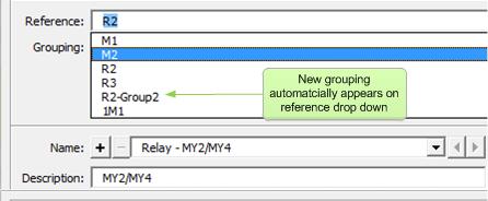
12 Symbols and wires in Electra have yellow control handles that let users easily re-position text. Simply drag on yellow control handles to move them to a new position. Individual shapes in a group (sub shapes) can be individually selected and formatted. Click on the group, and then click on the sub shape (not double click). Applying formats (e.g. font, alignment) to the group will affect all shapes in the group while applying formats to a sub shape in a group will only affect the individual shape. 12
 To enable the Reference window (shown left) to popup every time a new symbol is added to your drawings, check the \"Popup")

13 Electra provides the user with drawing options that can be accessed by: Click menu Electra Document Options (Visio 2010: Add-ins Electra Document Options) To enable the Reference window (shown left) to popup every time a new symbol is added to your drawings, check the "Popup Reference Window on drop" checkbox. For faster schematic generation, uncheck the "Popup Reference window on drop" check box. The Reference window will still be accessible by right clicking on a symbol and selecting "Edit Reference" even when automatic popup has been disabled. 13


14 User can select to show or hide symbol descriptions when dropping a symbol onto a drawing. To automatically show symbol descriptions, check the "Show Symbol Description on Drop" check box. Alternatively, right click on a symbol and select "Edit Reference" to show or hide symbol descriptions using the Reference window. Users can select to show or hide Pin names when dropping a symbol onto a drawing. To automatically show pin names, check the "Show Pin Names on Drop" check box. Alternative, right click on a symbol and select "Set Pin Names" to show, hide or edit pin names. See Also: Automatic Pin Names, Assigning Pin Names Page prefix in Electra is powerful and automatic. Once enabled, Page Prefix adds a page number in front of your symbol reference or wire name and automatically keeps track and updates this page number even when you re-order your pages, all automatically. On the example above, there is a coil named 1R1 on page 1, another coil 2R1 on page 2 and 2 contacts, each of them belonging to the coil at page 1 and 2 respectively (top row of the image). When page 3 is reordered as page 2 (bottom row of image), the coil 2R1 previously at page 2 is 14
15 now automatically renamed to 3R1 on page 3. The contact 2R1 is also renamed to 3R1 since the coil it is belonging to is now renamed to 3R1 on page 3. Users can select to prefix a page number on all references in a drawing by enabling the "Use Page Prefix on References" check box, and Electra will automatically insert and maintain all page prefixes. Alternatively, right click on a symbol and select "Edit Reference" to use Page Prefix. See Also: How Page Prefix Works Users can select to use page prefix for wires by enabling the "Use Page Prefix on Wires" check box and Electra will automatically insert and maintain all page prefixes. Alternatively, right click on a wire and select "Edit Wire" to use page prefix on a wire. Separator Examples , 2.100, P 1P100, 2P100, 1P101 / 1/100, 2/100, 1/101 Pg 1Pg100, 2Pg100, 1Pg101 The default separator for wires is the "." character (e.g ). Page prefix separator for wires can be any character but cannot be numeric (e.g. 0-9) and can consist of more than one character. See Also: How Page Prefix Works 15

16 Page Separator Examples /. /3.E7, /4.F8 P. P3.E7, P4.F8 Pg / Pg3/E7, Pg4/F8 Users can change the format in which Electra display the location of your symbols and wires, as shown in the examples at left: See Also: The AutoLocation Shape Electra reports shape locations (e.g. /1.A1 : Page 1 - zone A1) by dividing your drawing page into zones. To modify the location zones throughout your document, click on the Location tab on the Document Options window and enter your preferred zone spacing. See Also: The AutoLocation Shape 16
17 When you change the settings in Document Options, the settings will apply throughout the document (drawing file) and will be saved on the drawing file. If you wanted to set these settings as the default settings every time Electra is started, use the following steps: Make a backup copy of the file New Electra Drawing.vst (in C:\Program Files\Radica\Electra folder) Open Visio and Electra by double clicking on New Electra Drawing.vst. Select menu Electra Document Options and apply your custom settings Do not modify the drawing, and select menu Save As Type in your custom template name or overwrite New Electra Template.vst Close Visio and restart The settings are now saved into your own template. The next time you start Visio with your custom template, your settings will be used as the default. 17


18 On some occasions, users may want to create drawings that display symbols horizontally. At other times, users may want to create vertical ones. Electra makes it easy to do both, with one single shape. Shapes in Electra are intelligent, and can be rotated vertically or horizontally with a right click. Rotated shapes automatically move text and descriptions to the correct position. Certain shapes are even smarter. For example, the motor shape will allow users to place a 3 terminal or 6 terminal motor with a single right click. Drop a shape onto a drawing and right click to explore for more options. To place a symbol: Drag and drop a symbol from a stencil Symbols dropped from stencils inherits all formatting and data from its master shape in the stencil. To duplicate a symbol (2 methods): Click on a symbol in a drawing, then click copy and paste Click on a symbol, press CTRL key, drag and drop, then release the CTRL key Duplicated symbols inherits all formatting and data from the source symbol. Duplicating symbols are recommended when users wanted to preserve text or reference formatting. 18

19 Dropping a symbol by dragging from a stencil or by duplication and Electra will automatically and intelligently rename the new schematic symbol. If a symbol is dragged from a stencil, Electra will always rename the symbol by using its default reference. If a symbol is duplicated from an existing symbol, the new symbol will inherit all formatting and Electra will rename using the existing reference format. Create a new wire by dragging from a stencil or by duplication and Electra will automatically and intelligently rename the new wire. If a wire is dragged from a stencil, Electra will search through its internal sorted list and rename the new wire to the next sequential number. If a wire is duplicated from an existing wire, the new wire will inherit all formatting and Electra will rename using the existing wire name format. To edit the symbol reference (2 methods): Click on a symbol and type Double click on a symbol or Right click on a symbol and select "Edit Reference" 19

20 Included on the Reference window are real time cross reference information on shapes that you have already placed on your drawing. Click on a reference to display shapes and locations for that reference. To display pin names by default when you drop a symbol, check the "Show Pin Names On Drop" checkbox under menu Electra Document Options. Alternatively, right click on a symbol and select "Set Pin Names", then click on Hide or Show Pin names. 20


21 When symbols are dropped on a drawing, Electra automatically allocate the next available pin set to the symbol. When pin sets are not available or all used, Electra displays the pin names as red. Users can right click on a symbol and select "Set Pin Names" to manually allocate another pin set, show or hide pin names or add and edit pin sets. To access the Pin Names window: Right click on a symbol, then select "Set Pin Names" To assign another pin set: Select a pin set then click OK. To add, edit or delete pin set: Right click on any pin set and select your options 21

22 Symbols in Electra represents real world components, and the relationship can be any of the following: Relationship One symbol to one component One symbol to many components Many symbols to one component Many symbols to many components Example A power supply symbol represents a real world power supply. A relay symbol may represent a relay, a relay base and relay clips. Coil symbol, main contacts symbol and auxiliary contacts symbol all represent only a single contactor. Coil symbol and main contacts represents a contactor while multiple auxiliary contacts represents a single 4 pole auxiliary contact. Note: All symbols have the same reference. In Electra, all symbols with the same reference are initially organized into a single group, where they can be assigned to one or more components. Users can then divide the same symbols into further groupings, and each group can then to be assigned to one or more components. See Also: How Symbols are Matched to Components 22

23 To assign a component to a symbol: Right click on a symbol and select "Edit Reference" On the Reference Window, click on "Component" button 23


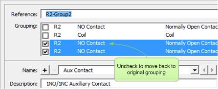
24 To assign and manage all symbols and components: Click on menu Electra Manage Components By default, all symbols with the same reference are grouped together. Users can then select to move some of the symbols to another group by unchecking the grouping box. Once unchecked, the symbols will automatically appear in another group ready to be assigned to another component. To move back the symbols to its original group, simply select and uncheck the group. 24
25 25

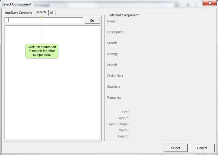
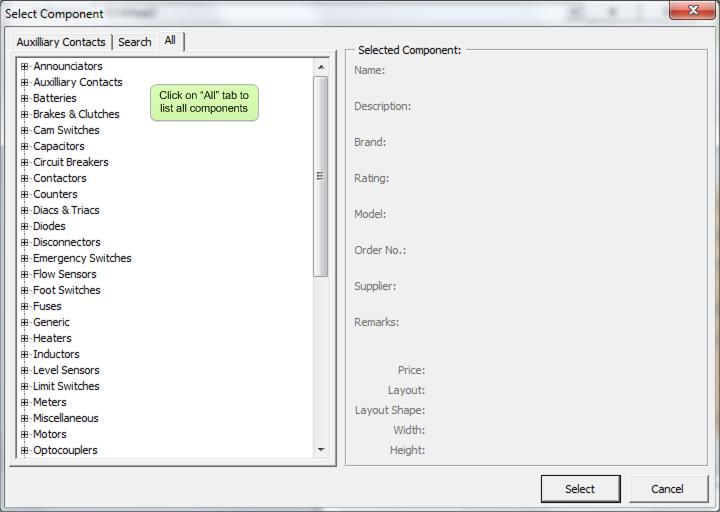
26 When users click the "Select" button on the Manage Components window, the Select Component window will be displayed: 26
27 27


28 To access the component database: Click on menu Electra Component Database The Component database stores all component specifications so that they can be used and reused on multiple projects and drawings. Once a component is selected, it's specifications is then transferred and stored on the drawing itself for portability. Components stored on the database are divided into categories and a single component can appear in more than one category. 28
29 29

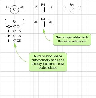
30 The AutoLocation displays the location of your selected reference automatically, as you add, modify or delete them, all without user interference. Locations will also update automatically when you move your symbols, even across multiple pages. Right click on the AutoLocation shape to jump to monitored references. Users can place multiple AutoLocation shapes to monitor a single reference on multiple pages. See Also: Location Format, Location Zone Options 30
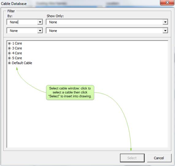
 No Yes Automatic Wire Name")
31 Electra provides numerous types of wires for every conceivable type of connection. Each of them can be easily stretched and manipulated by dragging on their handles. A normal line in Visio does not have data and intelligence as compared to a wire in Electra: Normal Visio Line Electra wires Automatic Wire Status Display (turns red) No Yes Automatic Wire Name Detection No Yes Automatic Wire Name Propagation No Yes Automatic Wire Connection No Yes Location Information No Yes Right click for Dots No Yes Detected by Terminals No Yes Wires in Electra are extremely flexible and can be stretched and manipulated in a variety of ways, by dragging on their handles, as shown below: 31
32 To edit a wire name (2 methods): Click on a wire and type Double click on a wire or Right click on a wire and select "Edit Wire" To show or hide wire name: Right click on a wire and select Show or Hide Wire Name 32
.")
.")
33 Included on the Wire window are real time cross reference information on wires that you have already placed on your drawing. To display the location of a wire, click on a wire name. (e.g. /1.J1 - Page 1, location J1). To set the current wire name to a wire name that already existed in your drawing, double click on a wire name in the Existing Wire Names list, and click OK. Wires in Electra will automatically be displayed in red when it does not have a wire name (orphaned). When a wire name is assigned to the wire, the wire will be displayed as black. 33


34 When a wire that has no wire name (red or orphaned) is dragged and moved to connect to another wire, Electra will automatically detect the new wire name and assign the new wire name to the orphaned wire. If you have multiple wires connected together, changing the wire name for the top most wire will also change the wire name for all the wires that is connected to the top most wire. Changed wire name will propagate to all connected wires, through wire links and even over multiple pages. 34


35 When a wire's end point is dropped on another wire, Electra automatically creates a connection point and connects the two wires together. When a connected wire is moved away, Electra automatically erases the connections points. Electra also automatically display a dot to denote a connection. Connection dots can be manually turned on/off by right clicking on the wire. When clicking on a wire, the red handle at the wire end denotes a connection, while other colors shows that there is NO connection. A connection can only be made when a wire end is connected to a connection point. See Also: Connection Points 35


.")
36 Wire links are used to extend a wire to another location, on the same page or to another page, while still symbolically representing a single wire. Use FromWireLink (source) to extend a wire to another location and use ToWireLink (target) to continue a wire from another location. Wire links can only be used in pairs, that is a source link (FromWireLink) that points to a target link (ToWireLink). Paired wire links always shows the location of the target paired link, and updates the location of the links automatically, even when moved. Right click on wire links to edit or modify links, or to jump to a paired link. 36


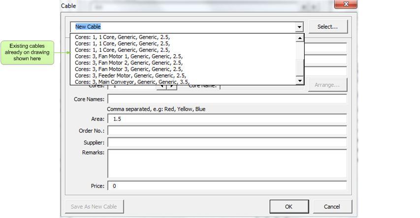
37 To assign a cable to a wire: Right click on a wire and select "Edit Wire" On the Wire Window, click on "Cable" button 37
38 38
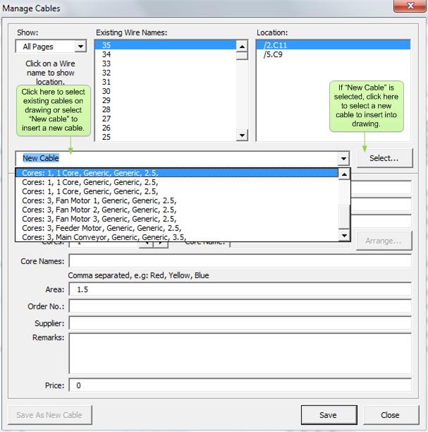
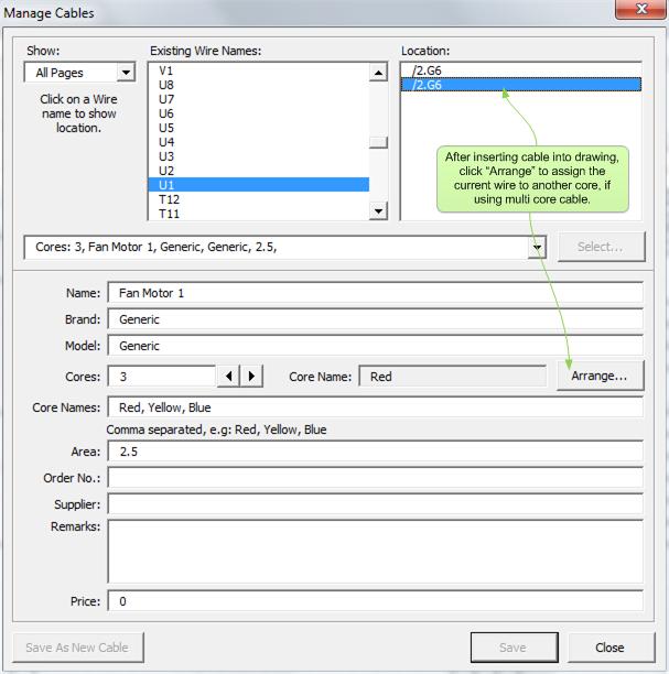
39 To assign and manage all cables: Click on menu Electra Manage Cables 39
40 40
41 41
42 42
43 43

44 When users click the "Select" button on the Manage Cables window, the Select Cable window will be displayed: 44


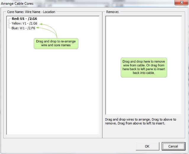
45 When users click the "Arrange" button on the Manage Cables window, the Arrange Cable Core window will be displayed: To access the cable database: Click on menu Electra Cable Database 45


46 The Cable database stores all cable specifications so that they can be used and re-used on multiple projects and drawings. Once a cable is selected, it's specifications is then transferred and stored on the drawing itself for portability. The Cable Tag shape is used on a drawing to automatically displays cable information for a wire. Drag and drop the cable tag on a wire and it will automatically display cable information for that wire. Right click on the cable tag for more options. 46
.")


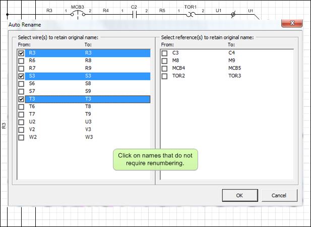
47 One of the most powerful and useful tool on Electra is its intelligent duplication of entire circuits. In most schematic drawings, there are similar circuits that is duplicated throughout the drawing (e.g. motor starter and control circuits). All references and wires on these circuits must be correctly and uniquely numbered. The issue is further complicated by the fact that certain symbols should be renumbered while others left unchanged (e.g. a common safety relay on motor control circuits should not be renumbered). Electra solves all this complexity by allowing users to choose wires and references that should be left unchanged and automatically and intelligently renumbering wires and references through its AutoRename window. 47
48 48
 circuits are circuits that is created and stored on a stencil to be easily re-used through drag and")
49 To duplicate and reuse your circuits: Select all the shapes in your circuit Click on the copy tool then click on the paste tool Select/Deselect symbols and wires to be renamed on the AutoRename window Click OK and then drag your new circuit to your desired location Pre-Fabricated (Prefab) circuits are circuits that is created and stored on a stencil to be easily re-used through drag and drop. Prefab circuits are extremely portable, and easily shared among different projects, teams or even online, simply by sharing the stencil on which it resides. Users basically make a circuit, store it in a stencil and re-use with minimal work and maximum portability. 49

50 To create a Prefab circuit: Draw a circuit as you would normally draw them Select all the shapes on your circuit Click on menu Electra Create Prefab Circuit Type in a name and description for your circuit Select the target stencil to store the circuit Click OK Your newly created prefab circuit will be then be stored in the stencil of your choosing, ready to be dragged and dropped onto your drawings. To share a prefab circuit, simply copy the stencil with the prefab circuit and make it available on a network drive to be shared among team members, or compress the stencil to be ed to anyone. Prefab circuits CANNOT be dragged and drop to another stencil. To move or duplicate Prefab circuits: Select menu Electra Duplicate Prefab Circuit Select the source stencil in which the Prefab circuit resides Select "All" to duplicate all prefab circuits or select a prefab circuit from the drop down Select the target stencil to store the prefab circuit Click OK 50

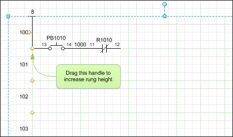
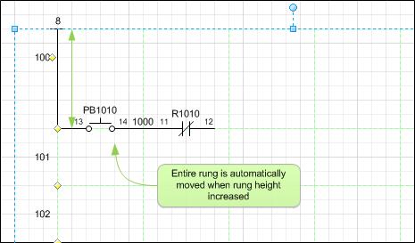
51 Your Prefab circuit will now be duplicated to the target stencil of your choosing. The original prefab circuit can now be deleted simply by click on the prefab circuit on the stencil and pressing the DEL key. 51


52 There are 2 types of terminal in Electra, terminal without numbers and terminal with numbers. Terminal with numbers will show terminal number when their terminal listing is generated while terminal without numbers will not show numbers during terminal list generation. Terminal symbols are always placed on a wire. In Electra, the terminal symbol will be displayed as red when it is not placed on a wire. When placed on a wire, it will automatically detect the underlying wire and will be displayed as black. To place a terminal, drag a wire onto the drawing and then drop a terminal on the wire. When a terminal symbol is dropped on a wire, the terminal symbol will automatically follow a wire like a magnet when the wire is moved or resized. To remove this behavior, drag and drop the terminal symbol away from a wire. 52
53 To generate terminal listing with numbers use the TerminalList with number. To generate terminal listing without numbers, use TerminalList without numbers. After placing all required terminals on your drawing, generate a terminal list by: Drag and place a TerminalList shape from the stencil Right click on the TerminalList shape, select Generate Listing Select Generate for all pages or this page only Click Generate If there are any addition and deletion of terminal symbols after generating your terminal list, simply right click on any TerminalList shape and generate again. Electra will automatically synchronize (create or delete) TerminalList shape based on your modifications. When users modify a wire name with a terminal on it, the wire name is automatically updated on the terminal listing. 53


54 Right click on any terminal listing to jump to the terminal symbol from which the terminal listing is generated. On the terminal symbol, right click to jump to the terminal listing. To manually create TerminalList, drag a TerminalList shape from the stencil or duplicate from your existing drawings. To edit the name of a manually created TerminalList, simply select the TerminalList and type in the name. To create spare TerminalList that is empty (no name) click on a TerminalList and press F2, then press delete. Alternatively, you can also name your spare TerminalList as "spare" by selecting the Terminal list and typing "spare". 54

55 Terminals are normally handled as blocks. Users may have one row of higher rated terminals and other rows of lower rated terminals. Electra enables a mix of terminals by providing the TerminalBlock shape. After generating your terminal list: Drag a TerminalBlock shape onto your drawing Drag and resize the TerminalBlock shape and ensure that it encapsulate all your TerminalList shape. Right click and select "ReNumber Terminals" to generate TerminalBlock with numbers TerminalBlock shapes will automatically calculate the quantity of TerminalList shape that it encapsulates. When you have newly added TerminalList shapes, click on the TerminalBlock shape, drag and resize using the handles and the TerminalBlock shape will automatically re-calculate your TerminalList. Alternatively, you can manually re-calculate by right clicking on the TerminalBlock shape and selecting "Count Terminals". 55
56 The TerminalBlock shape is also used during panel layout to generate a terminal block component. To properly identify your TerminalBlock shape and edit the TerminalBlock reference, right click on the TerminalBlock shape and select "Edit Terminal Block". Fields and meanings of the Edit Terminal Block as below: Fields Default Value Description Terminal Reference X1 Used as a reference to identify a terminal block Terminal Width 10 mm. The width of each terminal in the block. Accepts major units (e.g. mm, in, cm) Terminal Height 50 mm. The height of each terminal in the block. Accepts major units (e.g. mm, in, cm) Reference position Left Other values: Right, Top, Bottom. Select the reference text position Quantity position Right Other values: Left, Top Bottom. Select the quantity text position When you drag a TerminalBlock shape from the stencil, the TerminalBlock shape will be populated with default values. When you duplicate a Terminal Block shape from an existing one, it will inherit all the properties from the shape that it is copied from. For example, you may use terminals that is 15mm wide. Drag a TerminalBlock shape from the stencil, set the width property to 15mm, duplicate 3 more TerminalBlock shapes and all of them will inherit the properties and have the Terminal Width property set at 15mm. Alternatively, TerminalBlock properties can also be accessed by using the GenerateLayout window. 56
57 To generate panel layout, follow the process as listed below: Complete you schematic drawings Create a new page and set scale and measurement units Place base plates, cable ducts and rails on the new page Click on menu Electra Generate Layout and use the Generate Layout window to assign components Click on Generate or Generate All button to generate layout Use guides to place and align layout shapes Pages on the New Electra drawing template are set at 1:1 scale and measurement units set at inches. These page settings are optimized for schematic drawings. To prepare a page for panel layout drawings: Right click on a page tab and select insert page On the Page Setup dialog, select the Page Properties tab On the measurement units drop down, select millimeters On the Page Setup dialog, select the Drawing Scale tab Click on the custom scale radio button and type in your custom scale A scale of 1:5 is recommended for medium sized panels while a scale of 1:10 is recommended for larger panels. See Also: Page Scale, Page Measurement Units One of the first thing to do during panel layout drawings is to insert a plate (base plate or front plate). To insert a plate, select the Layout stencil and drag the plate icon to your drawing. All Plate shapes have automatic dimensions that you can show or hide by right clicking on the plate. Users can also set units for plates, cable ducts and rails to be displayed on a drawing by right clicking on these shapes. 57
58 To measure length and diameters, Electra provides dimensioning shapes on the Layout stencil to be dragged and dropped on drawings. All of them automatically display the dimension when their handles are dragged. Right click on dimension shapes for more options. To generate panel layout: Click menu Electra Generate Layout Ensure that all references are matched correctly with a component Click the Generate All button on the Generate Layout window Place and arrange the automatically generated components in your panel layout drawings Every time you run Generate Layout and click the Generate All button, Electra will automatically synchronize your drawings. For example, you may have added or deleted some symbols on your schematics, and Generate Layout will add in or delete components accordingly. If you have changed the references of your schematics, GenerateLayout will also automatically reflect this change in your layout. See Also: Understanding Symbols and Components, How Symbols are Matched to Components 58
 Once you have created a guide, drag")

59 To create a guide: Drag on the ruler in Visio Placing shapes on a guide: Drag shapes onto the guide (center of shape will turn red to indicate latching on guide) Once you have created a guide, drag your layout shapes to the guide to attach it to the guide (shape handles will turn red). When you move a guide, all shapes that are attached to the guide will automatically move and follow the guide. 59

60 To use the Layout 3D shapes, open the stencil "Layout3D E6.vss" in the C:\Program Files\Radica\Electra\ folder. Make sure the folder is opened in your document when you generate layout. All symbols in a drawing are divided into references Symbols with the same references are grouped together and can be divided into further groups Each group of symbols can be assigned to one or more components For each group of symbols, Electra looks for the symbol with the lowest priority to obtain the default component The default component can then be changed to any other component by users using the menu Electra Manage Components 60

61 To make your own layout shape: Draw lines, arcs and graphics or Import a CAD drawing and convert into Visio or Import an image of the layout shape Group all shapes and select them Click on menu Electra Create Layout Shape Type in a name and description for the layout shape Click OK An icon will be generated automatically when the layout shape is added to a stencil. Right click on the layout shape on the stencil and select Edit Icon to modify layout shape icon. After creating your custom icon for your layout shape, right click on the layout shape in the stencil, select Master Properties, and make sure to deselect Generate Icon automatically from shape data (In Visio 2010, it's called preview). 61
62 All reports that is generated in drawing automatically creates another report shape when a report overflows. This enables users to place reports over multiple pages when reports are long and cannot fit into a single page. To generate a Cross Reference report in a drawing: Drop the Cross Reference report shape onto your drawing Resize the report shape as required by dragging on the handles Right click and select Generate After generation, click once on the report shape, then click again on a column and resize the column by dragging on the handles To export the Cross Reference report, click on menu Electra Export Cross Reference Report 62

63 To generate a Material Reference report in a drawing: Drop the Material Reference report shape onto your drawing Resize the report shape as required by dragging on the handles Right click and select Generate After generation, click once on the report shape, then click again on a column and resize the column by dragging on the handles To export the Material Reference report, click on menu Electra Export Material Reference Report When exporting Material Reference, you will be shown the Reference tab. By default, all references will be selected to be exported. Users can now click on the references selectively, to select which to export. Multiple references can be selected by pressing the CTRL key or the SHIFT key and clicking on multiple references. The ability to choose references to export, enable users to choose a smaller set of references for editing in an Excel file, and later on, for the same Excel file to be imported back into the drawing. 63


64 To import a Material Reference report into a drawing: First, export a Material Reference report into Excel. The report MUST be exported with ALL fields for it to be successfully used as an import file. After report generation, add in rows of components by following the format in the report, delete or modify component information as required. Save the report in Excel. Then click on menu Electra Import Material Reference. Select the Excel file to be imported from. Then click the import button. After importing Material Reference, errors (if any) will be shown in the status box. The ability to import Material Reference report allows users to easily edit component information in batches, in a familiar spreadsheet environment, where these information can be easily copied from manufacturer's website and pasted into the spreadsheet. Once editing is complete, all these component information including dimensions can be easily imported back into a drawing. 64
65 To generate a Bills Of Material (BOM) report in a drawing: Drop the BOM report shape onto your drawing Resize the report shape as required by dragging on the handles Right click and select Generate After generation, click once on the report shape, then click again on a column and resize the column by dragging on the handles To export the BOM report, click on menu Electra Export Bills of Material Report 65

66 To generate a Cable Reference report in a drawing: Drop the Cable Reference report shape onto your drawing Resize the report shape as required by dragging on the handles Right click and select Generate After generation, click once on the report shape, then click again on a column and resize the column by dragging on the handles To export the Cable Reference report, click on menu Electra Export Cable Reference Report 66
67 To generate a Connections report in a drawing: Drop the Connections report shape onto your drawing Resize the report shape as required by dragging on the handles Right click and select Generate After generation, click once on the report shape, then click again on a column and resize the column by dragging on the handles To export the Connections report, click on menu Electra Export Connections Report 67

68 To create a PLC module in your drawings, drag and drop the PLC module shape onto your drawings. To rotate the PLC module shape: Right click on the PLC module shape and select Horizontal or Vertical To change the label position and orientation on the PLC module shape: Right click on the PLC module shape and select Change Label position or Change Label orientation All labels on the PLC Module shape can be customized by right clicking on the PLC module shape and selecting Set PLC Module. PLC modules can be input, output or analog modules. To customize the PLC module, type in a starting PLC point into the PLC point text box. If your PLC module is an input module and starts from B00000 to B00007, type in B00000 into PLC point text box. 68
69 PLC Point X0 B00001 Q0.0 Number of Points Max. Increment Original text box content Results after Generate 24Vdc Y01 Y02 24Vdc X0 X1 X2 X3 X4 X5 X6 X7 24Vdc X0 0Vdc 24Vdc B Vdc B00002 B00003 B00004 B00005 B00006 B00007 B00008 B00009 B00010 B00011 B Vdc Y01 0Vdc 24Vdc Q0.0 0Vdc Q0.1 Q0.2 Q0.3 Q0.4 Q0.5 Q0.6 Q0.7 Q1.0 Q1.1 Q1.2 Q1.3 Some PLC modules have addresses that ends with 7 and continues with 10 (e.g. X7, no X8 and continues at X10). Set the maximum increment to 7. Type in a value for the spacing between PLC points. The Spacing text box accepts measurement units, e.g. inches, millimeters, cm and other units. After setting PLC point, number of points and maximum increment, click on the Generate button to generate your PLC points. The generated points will be shown on the text box under the Generate button. Examples of generation at left: Users can also manually create PLC points by using the PLC labels text box under the Generate button. Type in the desired labels and press the Enter key. The PLC Module will automatically generate PLC point labels for each line of text in the PLC labels text box. You can use the PLC Module shape to create input and output modules and they will be displayed as separate shapes on your drawing. If you edit their reference (e.g both input and output module are "PLC1") then Electra understands that both symbols represent only a single PLC module. Therefore, only a single PLC module appears on Generate Layout or on the Bills of Materials, despite having 2 separate PLC module shape on your drawings. 69

70 Drag and drop the LadderZone shape onto your drawings to create ladder diagrams. Symbols and wires in a ladder zone gets automatically renamed according to their rung numbers. If a number is used, it is automatically incremented to the next number. To increase the height of a rung, drag on the yellow controls handles on the LadderZone shape. All symbols attached to a rung you have moved will be automatically moved also. To use the LadderZone shape: Drag and drop the LadderZone shape onto your drawing 70
71 71

72 Rung numbers, and ladder zone sizing can be customized by right clicking on the LadderZone shape and selecting "Set Ladder Zone". The LadderZone shape has green grid lines that are for display only and is not printable. 72


73 Creating your own intelligent schematic symbol is an easy and automated process: Draw symbols using lines, circles, arcs and text Group all shapes and add connection points Select shape and click on menu Electra Create Schematic Symbol 73

74 The Create Symbol window is used to automatically insert intelligence and data into your custom symbol in order for it to be correctly identified and processed by Electra. 74
75 Default Reference Default reference for your custom symbol (e.g. R1) Description text box No Description check box Vertical by default Hide Description Insert Horizontal / Vertical rotation menu Category Most schematic symbols have a symbol description (e.g. Start button) displayed at the bottom of the symbol. If a symbol description box does not yet exist on your custom symbol, the Create Symbol window will automatically add in a symbol description box. To disable automatic adding of a symbol description box, check the No Description check box. When you have selected to include a symbol description in your custom symbol, use the description text box to type in the default symbol description. If you are creating a symbol which is vertical by default when dropped on a drawing, check the vertical by default check box. Check to hide description by default. Once a symbol is dropped on a drawing, users can select to show or hide the description text by right clicking on the symbol and select "Edit Reference" To insert a horizontal / vertical rotation menu into your custom symbol, check the Insert Horizontal / Vertical rotation menu check box. The horizontal / vertical menu enables you to have one symbol for both horizontal and vertical drawings, similar to symbols provided by Electra. If you assign your symbol to a category, during component selection you will be presented with components for that category only. This makes for easier and faster component selection. Categories are guides only and during component selection the user can still select a component in other categories no matter what category a symbol belongs to. 75

76 All schematic symbols in Electra have a link to a component. This link is used by Electra to automatically match one or more symbols to one or more component during panel layout and reports. Priority All schematic symbols in Electra have a priority number that is used to match a group of symbols with the same references to a component. The lowest priority number in a group of symbols with the same references will be used to suggest a default component. For user created custom symbols, a priority number of 15 is recommended. Location Type The Location Type combo box is used by the Location or AutoLocation shape to identify the symbol type. For example, a coil symbol should be set to location type Coil, a normally closed contact should be set to location type NC and a normally open contact should be set to location type NO. See Also: Understanding Symbols and Components, How Symbols are Matched to Components 76
. Pin Names comes in sets. For example, a standard NO (2 pole) can have 13 / 14, 23 / 24 etc as pin names.")
77 All symbols with connection points can have a set of pin names assigned to the connection points. Pin Set Position Each connection point has a pin name. If none were entered, Electra will use defaults (blank). Pin Names comes in sets. For example, a standard NO (2 pole) can have 13 / 14, 23 / 24 etc as pin names. 13 / 14 is one set of pin names and 23 / 24 is another set of pin names. To specify numerous sets of pin name for a single pin, type in all the possible pin names for that pin separated by commas, e.g. 13, 23. Then cycle to the next pin to repeat the same and type 14, 24 as pin names. Click on any 8 of the radio buttons to set the pin name position relative to the connection point. You will be able to see how your selection affects the position of the pin name on the right side of the above window. Text Orientation Select horizontal or vertical text for your pin name text orientation. See Also: Displaying Pin Names, Automatic Pin Names, Assigning Pin Names When you wanted detailed control the width and height of the description textbox, use the width and height text box. 77
78 After setting all the options on the Create Symbol window, click the OK button and Create Symbol will: Insert intelligence and data into your custom symbol Open the selected stencil and add your custom symbol onto the stencil Delete the custom symbol from your drawing (For Electra to identify your custom symbol, it must originate from a stencil) To modify and edit your symbol: Drag your symbol onto your drawing Modify it and use the Create Symbol window again to add it back into a stencil An icon will be generated automatically when the symbol is added to a stencil. Right click on the symbol on the stencil and select Edit Icon to modify symbol icon. After creating your custom icon for your symbol, right click on the symbol in the stencil, select Master Properties, and make sure to deselect Generate Icon automatically from shape data (In Visio 2010 it's called a preview). 78

79 A title block can consist of the following: Static Text Static Graphics Automatic Text User Data (Document Scope) User Data (Page Scope) Text that does not change over projects or pages, e.g. addresses or company names. Graphics that does not change. e.g. logos or client logos. Automatic fields that is automatically updated by Visio, e.g. editing dates, scale and page numbers. User editable data that applies for a single project, e.g. Project name, site name or any data that applies over the entire project. User editable data that applies for the current page only, e.g. page title, page author, etc. In Electra, there are tools that makes it easy to make your own custom title blocks that includes all of the above. 79

80 To create your own title block: Insert title block zones onto a blank page Insert static text and static graphics Insert automatic text Insert user data (page or document scope) Group all shapes together Select all and click menu Electra Title Blocks Create Title Block Type in a name and a prompt for your title block and click OK The title block zones automatically setup and divide your page into location zones based on your settings in menu Electra Document Options. See Also: Location Zone Options Use drawing and text tools on Visio to create graphics and text or import an image. If necessary, group them and place them in the desired location on your title block. 80

81 81 Electra provides a host of automatic shapes including pages, scales and editing dates that can be placed on your title blocks. Just drag and drop them onto your drawing from the Title Block stencil. Right click on them for more options and place them in your desired location.


82 To create User Data: Draw a box and select it Click menu Electra Title Blocks Insert Title Block Data Type in a name for your User Data, e.g. Project or Page Author Type in the default value for the User Data Select Document scope for data that applies throughout the document or Page scope for data that applies for current page only The User Data rectangle is now ready to be used on your custom title block. Drag the handles of the rectangle to position and resize your user data. Upon completion, users can edit these User Data by right clicking on the title block. After selecting all shapes that make up your custom title block, group them together, the click on menu Electra Title Blocks Create Title Block. Type in a name and prompt for your custom title block, and click ok. Your new custom title block will now be saved and stored in the Title Block stencil ready to be used. 82
83 To use your custom title block: Drag and drop your custom title block from stencil onto your drawing Your custom title block will automatically center on your drawing. To edit and modify User Data: Right click on the title block and select "Edit Title Block" An icon will be generated automatically when the title block is added to a stencil. Right click on the title block on the stencil and select Edit Icon to modify the icon. After creating your custom icon for your title block, right click on the title block in the stencil, select Master Properties, and make sure to deselect Generate Icon automatically from shape data (In Visio 2010 it's called a preview). 83


84 To use Table of Contents: Users must use the "Title" Automatic Text block from the Title Block stencil Insert the "Title" Automatic text into your Title Block and create your own title block Insert your custom title block into drawing Insert Table of Contents (TOC) report from the Reports stencil into your drawing Right click and select "Generate Report" and Electra will automatically scan every page to create a Table of Contents 84

85 To access the stencil browser: Click on menu Electra Stencil Browser The stencil browser is a utility to edit symbols after their creation. Users could browse stencils containing symbols and edit their component or pin information without recreating a symbol. 85


86 To export a stencil: Click on menu Electra Export Stencils Select the stencil to export Exporting stencil and symbol information to Excel enable users to edit these information in batches rather than individually using the Stencil Browser. 86

87 After exporting symbol information from a stencil into Excel, and upon completion of editing these information, they can then be imported back into Electra: Click menu Electra Import Stencils Select to stencil to import into Select the Excel file that contains symbol and stencil information Click OK Updated symbol information will then be automatically imported to the stencil. 87

88 The Renumber utility is used to renumber a batch of symbols or wires with the same format into other numbers. When a user drops a Master shape or symbol from a stencil onto a drawing, Visio automatically inserts the master shape into a special stencil called the document stencil. When a user deletes a symbol from a drawing, these Master shapes get left behind in the document stencil even though they are no longer used and causes the entire document to increase in size. Run the "Clean Up Document" utility, and Electra will scan the entire document and remove all unused Master shapes to reduce file sizes. Using the Reload document menu, users can re-scan Electra drawings without the need to save, close and re-open a document when an unhandled error is encountered. 88
89 Electra requires: Microsoft Visio 2003 or later Works with all versions of Visio including standard, professional, technical and academic editions (only 32-bit versions) DOES NOT WORK on all Office / Visio 64-bit versions as Microsoft has not worked out compatibility problems with 64-bit versions. Microsoft has recommended AGAINST installing Office 64-bit unless absolutely necessary. Please refer to the below for more information: Microsoft TechNet Microsoft TechNet Blog PC World Works with Visio (32-bit) on all platforms including Win XP, Win Vista (x86 & x64), Win 7 (x86 & x64) Electra is a Microsoft Visio solution and requires Microsoft Visio to operate. It is strongly recommended that you install Visio before installing Electra. To install Visio, follow the instructions listed on the Visio documentation. To install Electra: Exit any applications you are running Double click on the installer and run the installer program Read the installer warning regarding closing any applications that you may be running and click OK Read the End User License Agreement and if you agree to the terms, click Accept Click on the installation button to begin installing To activate your copy of Electra: Click menu Electra About Electra Click on Edit button and paste/type in your serial number, then click Save Click on Activate button to activate 89

90 Electra uses macros in Visio. If your installed copy of Visio is set to High or Medium security, you may be prompted for permission to run a macro every time Electra is activated or have Electra disabled altogether. To enable macros and Electra: Start Electra by double clicking on New Electra Drawing.vst Visio will ask you about trusting us as a publisher, as listed below. Click Trust all from publisher In Visio 2010, you will also be asked to turn on macros as listed below. Click on Enable Macros 90
Tutorial. COPYRIGHT 2014 IGE+XAO. All rights reserved TUTORIAL. Your first steps with SEE Electrical Expert. The specialist of electrical software
 TUTORIAL Your first steps with SEE Electrical Expert The specialist of electrical software Page 2 A.1. Conventions used in this tutorial TABLE OF CONTENTS A OVERVIEW... 5 A.1. CONVENTIONS USED IN THIS
Designer Reference 1
 Designer Reference 1 Table of Contents USE OF THE DESIGNER...4 KEYBOARD SHORTCUTS...5 Shortcuts...5 Keyboard Hints...5 MENUS...7 File Menu...7 Edit Menu...8 Favorites Menu...9 Document Menu...10 Item Menu...12
Creating electrical designs
 Creating electrical designs 27.09.2018-34 TABLE OF CONTENTS Table of contents... 2 Introduction... 4 What you learn with this content... 5 Starting G-Electrical... 6 Interface... 6 Drawing area (1)...
ekaizen Lessons Table of Contents 1. ebook Basics 1 2. Create a new ebook Make Changes to the ebook Populate the ebook 41
 Table of Contents 1. ebook Basics 1 2. Create a new ebook 20 3. Make Changes to the ebook 31 4. Populate the ebook 41 5. Share the ebook 63 ekaizen 1 2 1 1 3 4 2 2 5 The ebook is a tabbed electronic book
Using SymPrint to Make Overlays, Templates & More...
 Welcome to SymPrint SymPrint is an easy-to-use tool for creating communication overlays, worksheets, classroom activities and more using a modern toolbar and common-sense interface modeled after the programs
Numbers Basics Website:
 Website: http://etc.usf.edu/te/ Numbers is Apple's new spreadsheet application. It is installed as part of the iwork suite, which also includes the word processing program Pages and the presentation program
User Guide. Product Design. Version 2.2.2
 User Guide Product Design Version 2.2.2 Table of Contents Bridge User Guide - Table of Contents 1 TABLE OF CONTENTS... 1 INTRODUCTION... 4 Guide... 4 PRODUCTS... 5 Creating a New Product... 5 Viewing and
Getting_started_EN (Ind : 3) 06/01/2014. elecworks. Getting Started
 06/01/2014. elecworks. Getting Started") Getting_started_EN (Ind : 3) 06/01/2014 elecworks Getting Started 1 Start with elecworks This document has been made to help you in starting elecworks. It summarizes the features available. If you would
Getting_started_EN (Ind : 3) 06/01/2014 elecworks Getting Started 1 Start with elecworks This document has been made to help you in starting elecworks. It summarizes the features available. If you would
Chapter 2 Using Slide Masters, Styles, and Templates
 Impress Guide Chapter 2 Using Slide Masters, Styles, and Templates OpenOffice.org Copyright This document is Copyright 2007 by its contributors as listed in the section titled Authors. You can distribute
Victaulic Tools for Revit
 Victaulic Tools for Revit User Manual Revit 2016, 2017, 2018 Table of Contents Introduction Section 01 Licensing Page 3 Section 02 Pipe Tools (Pipe / Duct Splitting) Page 4 Section 03 Pipe Tools (Pipe
Piping & Instrumentation Diagrams
 Page 1 Piping & Instrumentation Diagrams Preface Using This Guide What's New? Getting Started Entering the Workbench Setting up Working Units and Grid Placing Components Routing a Piping Line or I & C
Microsoft. Microsoft. Microsoft Visio Duration: 16hrs
 Visio 2010 Duration: 16hrs Target Audience: This course is designed for users who need to use the diagramming capabilities with Visio 2010. Pre-requisites: Basic knowledge of Windows operating system knowledge
Generating a Custom Bill of Materials
 Generating a Custom Bill of Materials Old Content - visit altium.com/documentation Modified by on 6-Nov-2013 This tutorial describes how to use the Report Manager to set up a Bill of Materials (BOM) report.
CPM-200 User Guide For Lighthouse for MAX
 CPM-200 User Guide For Lighthouse for MAX Contents Page Number Opening the software 2 Altering the page size & Orientation 3-4 Inserting Text 5 Editing Text 6 Inserting Graphics 7-8 Changing the Colour
Creating Interactive PDF Forms
 Creating Interactive PDF Forms Using Adobe Acrobat X Pro for the Mac University Information Technology Services Training, Outreach, Learning Technologies and Video Production Copyright 2012 KSU Department
AutoCAD 2009 User InterfaceChapter1:
 AutoCAD 2009 User InterfaceChapter1: Chapter 1 The AutoCAD 2009 interface has been enhanced to make AutoCAD even easier to use, while making as much screen space available as possible. In this chapter,
Using Microsoft Word. Working With Objects
 Using Microsoft Word Many Word documents will require elements that were created in programs other than Word, such as the picture to the right. Nontext elements in a document are referred to as Objects
Forms/Distribution Acrobat X Professional. Using the Forms Wizard
 Forms/Distribution Acrobat X Professional Acrobat is becoming a standard tool for people and businesses to use in order to replicate forms and have them available electronically. If a form is converted
Report Designer Report Types Table Report Multi-Column Report Label Report Parameterized Report Cross-Tab Report Drill-Down Report Chart with Static
 Table of Contents Report Designer Report Types Table Report Multi-Column Report Label Report Parameterized Report Cross-Tab Report Drill-Down Report Chart with Static Series Chart with Dynamic Series Master-Detail
OX Documents Release v Feature Overview
 OX Documents Release v7.8.4 Feature Overview 1 Objective of this Document... 3 1.1 The Purpose of this Document... 3 2 General Improvements... 4 2.1 Security First: Working with Encrypted Files (OX Guard)...
Piping & Instrumentation Diagrams
 Piping & Instrumentation Diagrams Preface Using This Guide What's New? Getting Started Entering the Workbench Setting up Working Units and Grid Placing Components Routing a Piping Line or I & C Loop Placing
End User Guide. 2.1 Getting Started Toolbar Right-click Contextual Menu Navigation Panels... 2
 TABLE OF CONTENTS 1 OVERVIEW...1 2 WEB VIEWER DEMO ON DESKTOP...1 2.1 Getting Started... 1 2.1.1 Toolbar... 1 2.1.2 Right-click Contextual Menu... 2 2.1.3 Navigation Panels... 2 2.1.4 Floating Toolbar...
Configuring Ad hoc Reporting. Version: 16.0
 Configuring Ad hoc Reporting Version: 16.0 Copyright 2018 Intellicus Technologies This document and its content is copyrighted material of Intellicus Technologies. The content may not be copied or derived
Microsoft Visio 2016 Foundation. Microsoft Visio 2016 Foundation Level North American Edition SAMPLE
 Microsoft Visio 2016 Foundation Microsoft Visio 2016 Foundation Level North American Edition Visio 2016 Foundation - Page 2 2015 Cheltenham Group Pty. Ltd. All trademarks acknowledged. E&OE. No part of
HVAC Diagrams Preface What's New? Getting Started User Tasks
 HVAC Diagrams Preface Using This Guide What's New? Getting Started Entering the Workbench Setting up Working Units and Grid Placing Components Routing an HVAC Line Placing Components in a Line Repositioning
Impress Guide Chapter 11 Setting Up and Customizing Impress
 Impress Guide Chapter 11 Setting Up and Customizing Impress This PDF is designed to be read onscreen, two pages at a time. If you want to print a copy, your PDF viewer should have an option for printing
InDesign CS Basics. To learn the tools and features of InDesign CS to create publications efficiently and effectively.
 InDesign CS Basics InDesign Basics Training Objective To learn the tools and features of InDesign CS to create publications efficiently and effectively. What you can expect to learn from this class: How
User Manual. pdoc Forms Designer. Version 3.7 Last Update: May 25, Copyright 2018 Topaz Systems Inc. All rights reserved.
 User Manual pdoc Forms Designer Version 3.7 Last Update: May 25, 2018 Copyright 2018 Topaz Systems Inc. All rights reserved. For Topaz Systems, Inc. trademarks and patents, visit www.topazsystems.com/legal.
PowerPoint 2016 Building a Presentation
 PowerPoint 2016 Building a Presentation What is PowerPoint? PowerPoint is presentation software that helps users quickly and efficiently create dynamic, professional-looking presentations through the use
Basic Concepts. Launching MultiAd Creator. To Create an Alias. file://c:\documents and Settings\Gary Horrie\Local Settings\Temp\~hh81F9.
 Page 1 of 71 This section describes several common tasks that you'll need to know in order to use Creator successfully. Examples include launching Creator and opening, saving and closing Creator documents.
CounselLink Reporting. Designer
 CounselLink Reporting Designer Contents Overview... 1 Introduction to the Document Editor... 2 Create a new document:... 2 Document Templates... 3 Datasets... 3 Document Structure... 3 Layout Area... 4
L E S S O N 2 Background
 Flight, Naperville Central High School, Naperville, Ill. No hard hat needed in the InDesign work area Once you learn the concepts of good page design, and you learn how to use InDesign, you are limited
Creating Reports in Access 2007 Table of Contents GUIDE TO DESIGNING REPORTS... 3 DECIDE HOW TO LAY OUT YOUR REPORT... 3 MAKE A SKETCH OF YOUR
 Creating Reports in Access 2007 Table of Contents GUIDE TO DESIGNING REPORTS... 3 DECIDE HOW TO LAY OUT YOUR REPORT... 3 MAKE A SKETCH OF YOUR REPORT... 3 DECIDE WHICH DATA TO PUT IN EACH REPORT SECTION...
Window Designer. Opening Screen: When you start Window Designer, you will see the Opening Screen. Here you will be choosing from 4 options:
 Window Designer Opening Screen: When you start Window Designer, you will see the Opening Screen. Here you will be choosing from 4 options: New Design: Use this option when no pre-built templates are available
Specification Manager
 Enterprise Architect User Guide Series Specification Manager How to define model elements simply? In Sparx Systems Enterprise Architect, use the document-based Specification Manager to create elements
Welcome to MicroStation
 Welcome to MicroStation Module Overview This module will help a new user become familiar with the tools and features found in the MicroStation design environment. Module Prerequisites Fundamental knowledge
Microsoft PowerPoint 2016 Basics Unit 9 Final Review - Student Notes Directions: Fill in the blanks.
 Directions: Fill in the blanks. 1. PowerPoint Window Layout 2. File Tab When clicked, opens - automatically opens the Info option by default Holds the following options: - Info - New - Open - Save - Save
Center for Faculty Development and Support Making Documents Accessible
 Center for Faculty Development and Support Making Documents Accessible in Word 2007 Tutorial CONTENTS Create a New Document and Set Up a Document Map... 3 Apply Styles... 4 Modify Styles... 5 Use Table
Beginning a presentation
 L E S S O N 2 Beginning a presentation Suggested teaching time 40-50 minutes Lesson objectives To learn how to create and edit title and bullet slides, you will: a b c d Select slide types by using the
How to use the ruler, grid, guides, and the Align panel
 How to use the ruler, grid, guides, and the Align panel Much of your job as a page designer is to place text and graphics on the page in a pleasing, organized way. Although you can do much of this placing
A Study of Angles & Curves
 A Study of Angles & Curves Method 1: Cutting Quilt Shapes/Using the Shapes Tools Open BERNINA CutWork Software. Make sure that Create New is selected. Click Next. Place a dot in front of New Graphic. Select
MockupScreens - User Guide
 MockupScreens - User Guide Contents 1. Overview...4 2. Getting Started...5 Installing the software... 5 Registering... 9 3. Understanding the Interface...11 Menu Bar... 11 Tool bar... 14 Elements... 14
Solo 4.6 Release Notes
 June9, 2017 (Updated to include Solo 4.6.4 changes) Solo 4.6 Release Notes This release contains a number of new features, as well as enhancements to the user interface and overall performance. Together
Basic WorkflowChapter1:
 Chapter 1 Basic WorkflowChapter1: This chapter describes the AutoCAD Electrical version of AutoCAD software. AutoCAD Electrical is created for electrical engineers who design industrial control systems.
Adobe Acrobat Pro DC for Windows
 Adobe Acrobat Pro DC for Windows Creating Interactive PDF Forms University Information Technology Services Learning Technologies, Training & Audiovisual Outreach Copyright 2017 KSU Division of University
SETTING UP A. chapter
 1-4283-1960-3_03_Rev2.qxd 5/18/07 8:24 PM Page 1 chapter 3 SETTING UP A DOCUMENT 1. Create a new document. 2. Create master pages. 3. Apply master pages to document pages. 4. Place text and thread text.
IBM TRIRIGA Application Platform Version 3.3. Graphics User Guide. Copyright IBM Corp i
 IBM TRIRIGA Application Platform Version 3.3 Graphics User Guide Copyright IBM Corp. 2011 i Note Before using this information and the product it supports, read the information in Notices on page 33. This
User Guide 701P Wide Format Solution Wide Format Scan Service
 User Guide 701P44865 6204 Wide Format Solution Wide Format Scan Service Xerox Corporation Global Knowledge & Language Services 800 Phillips Road Bldg. 845-17S Webster, NY 14580 Copyright 2006 Xerox Corporation.
How to Mail Merge PDF Documents
 How to Mail Merge PDF Documents A step-by-step guide to creating personalized documents using AutoMailMerge plug-in for Adobe Acrobat Table of Contents What is a mail merge?...2 What do I need to start?...2
Using the reporting function
 11/17 ArtemiS SUITE 1 provides a very versatile reporting functionality, which makes it easy for you to present your analysis results in clearly arranged reports. This describes the first steps with this
VisualPST 2.4. Visual object report editor for PowerSchool. Copyright Park Bench Software, LLC All Rights Reserved
 VisualPST 2.4 Visual object report editor for PowerSchool Copyright 2004-2015 Park Bench Software, LLC All Rights Reserved www.parkbenchsoftware.com This software is not free - if you use it, you must
Intellicus Enterprise Reporting and BI Platform
 Configuring Ad hoc Reporting Intellicus Enterprise Reporting and BI Platform Intellicus Technologies info@intellicus.com www.intellicus.com Copyright 2012 Intellicus Technologies This document and its
A Step-by-step guide to creating a Professional PowerPoint Presentation
 Quick introduction to Microsoft PowerPoint A Step-by-step guide to creating a Professional PowerPoint Presentation Created by Cruse Control creative services Tel +44 (0) 1923 842 295 training@crusecontrol.com
Nexans FibreRoute Planner User Manual. Installation Guide September 2017
 User Manual Installation Guide September 2017 2 Table of Contents 1. 1.1 2. Introduction 4 Application in Data Centre... 5 8 2.1 Nexans FibreRoute stencils... 10 2.1.1 stencil... 11 2.1.1.1 IT and AC Rack
LinkMotion and CorelDraw 9, 10, 11, 12, X3, X4, X5, X6, X7 and X8:
 LinkMotion and CorelDraw 9, 10, 11, 12, X3, X4, X5, X6, X7 and X8: After you install LinkMotion software and set up all settings launch CorelDraw software. Important notes: Solustan s LinkMotion driver
EE 210 Lab Assignment #2: Intro to PSPICE
 EE 210 Lab Assignment #2: Intro to PSPICE ITEMS REQUIRED None Non-formal Report due at the ASSIGNMENT beginning of the next lab no conclusion required Answers and results from all of the numbered, bolded
Chapter 1. Getting to Know Illustrator
 Chapter 1 Getting to Know Illustrator Exploring the Illustrator Workspace The arrangement of windows and panels that you see on your monitor is called the workspace. The Illustrator workspace features
Quick Start Guide. Microsoft Visio 2013 looks different from previous versions, so we created this guide to help you minimize the learning curve.
 Quick Start Guide Microsoft Visio 2013 looks different from previous versions, so we created this guide to help you minimize the learning curve. Updated templates Templates help you start the drawing type
PowerPoint 2007 Cheat Sheet
 ellen@ellenfinkelstein.com 515-989-1832 PowerPoint 2007 Cheat Sheet Contents Templates and Themes... 2 Apply a corporate template or theme... 2 Format the slide master... 2 Work with layouts... 3 Edit
User Manual Version 1.1 January 2015
 User Manual Version 1.1 January 2015 - 2 / 112 - V1.1 Variegator... 7 Variegator Features... 7 1. Variable elements... 7 2. Static elements... 7 3. Element Manipulation... 7 4. Document Formats... 7 5.
Guide to WB Annotations
 Guide to WB Annotations 04 May 2016 Annotations are a powerful new feature added to Workbench v1.2.0 (Released May 2016) for placing text and symbols within wb_view tabs and windows. They enable generation
OpenForms360 Validation User Guide Notable Solutions Inc.
 OpenForms360 Validation User Guide 2011 Notable Solutions Inc. 1 T A B L E O F C O N T EN T S Introduction...5 What is OpenForms360 Validation?... 5 Using OpenForms360 Validation... 5 Features at a glance...
Adobe InDesign CS6 Tutorial
 Adobe InDesign CS6 Tutorial Adobe InDesign CS6 is a page-layout software that takes print publishing and page design beyond current boundaries. InDesign is a desktop publishing program that incorporates
Impress Guide. Chapter 11 Setting Up and Customizing Impress
 Impress Guide Chapter 11 Setting Up and Customizing Impress Copyright This document is Copyright 2007 2013 by its contributors as listed below. You may distribute it and/or modify it under the terms of
PowerPoint 2010 Level 1 Computer Training Solutions Student Guide Version Revision Date Course Length
 Level 1 Computer Training Solutions Version 1.2 Revision Date Course Length 2012-Feb-16 6 hours Table of Contents Quick Reference... 3 Frequently Used Commands... 3 Manitoba ehealth Learning Management
Chapter 2 Using XG5000 Software. 2.1 Screen Configuration. XG5000 screen is composed as shown below. [Screen of XG5000]
![Chapter 2 Using XG5000 Software. 2.1 Screen Configuration. XG5000 screen is composed as shown below. [Screen of XG5000]](/thumbs/95/123656432.jpg "Chapter 2 Using XG5000 Software. 2.1 Screen Configuration. XG5000 screen is composed as shown below. [Screen of XG5000]") 2.1 Screen Configuration XG5000 screen is composed as shown below. [Screen of XG5000] a b f c d e [Description of screen component] a. Menu bar: It is the basic menu bar for the XG5000 software. b. Tool
2.1 Screen Configuration XG5000 screen is composed as shown below. [Screen of XG5000] a b f c d e [Description of screen component] a. Menu bar: It is the basic menu bar for the XG5000 software. b. Tool
Chapter11 practice file folder. For more information, see Download the practice files in this book s Introduction.
 Make databases user friendly 11 IN THIS CHAPTER, YOU WILL LEARN HOW TO Design navigation forms. Create custom categories. Control which features are available. A Microsoft Access 2013 database can be a
Microsoft Access II 1.) Opening a Saved Database Music Click the Options Enable this Content Click OK. *
 Opening a Saved Database Music Click the Options Enable this Content Click OK. *") Microsoft Access II 1.) Opening a Saved Database Open the Music database saved on your computer s hard drive. *I added more songs and records to the Songs and Artist tables. Click the Options button next
Microsoft Access II 1.) Opening a Saved Database Open the Music database saved on your computer s hard drive. *I added more songs and records to the Songs and Artist tables. Click the Options button next
DYMO ID User Guide BC
 DYMO ID User Guide BC Copyright 2015 Sanford, L.P. All rights reserved. Revised: 4/28/2015 No part of this document or the software may be reproduced or transmitted in any form or by any means or translated
Word 2007 Tables Objectives
 Word 2007 Tables In this lesson you will learn how to create, modify and format tables. You will also learn to use the AutoFormat table option and to sort table rows. Objectives Create a table Modify a
IGSS 13 Configuration Workshop - Exercises
 IGSS 13 Configuration Workshop - Exercises Contents IGSS 13 Configuration Workshop - Exercises... 1 Exercise 1: Working as an Operator in IGSS... 2 Exercise 2: Creating a new IGSS Project... 28 Exercise
Keynote 08 Basics Website:
 Website: http://etc.usf.edu/te/ Keynote is Apple's presentation application. Keynote is installed as part of the iwork suite, which also includes the word processing program Pages and the spreadsheet program
Reporting Center. Primary (Stand-Alone) Interface
 Interface") Reporting Center The Reporting Center is where you will go to run or create reports on projects. It can be accessed in any of the follow ways, each with a slightly different user interface and functionality.
Reporting Center The Reporting Center is where you will go to run or create reports on projects. It can be accessed in any of the follow ways, each with a slightly different user interface and functionality.
Scoreboards. The two types of scoreboards are: There are two options associated with scoreboards:
 Scoreboards Using Match and Team Scoreboards with the STRONGVON Administration Software 1 Overview The full version of the STRONGVON Administration Software (TSW) provides you with different scoreboards
N L F A C I L I T I E S T U T O R I A L
 N L F A C I L I T I E S T U T O R I A L NEWRON SYSTEM 25-27 Boulevard Victor HUGO 31770 COLOMIERS (France) T: +33 (0)5 61 15 18 45 F: +33 (0)5 61 15 16 44 Copyright NEWRON SYSTEM 2001-2007 Document version
How to Get Started. Figure 3
 Tutorial PSpice How to Get Started To start a simulation, begin by going to the Start button on the Windows toolbar, then select Engineering Tools, then OrCAD Demo. From now on the document menu selection
User Guide. Web Intelligence Rich Client. Business Objects 4.1
 User Guide Web Intelligence Rich Client Business Objects 4.1 2 P a g e Web Intelligence 4.1 User Guide Web Intelligence 4.1 User Guide Contents Getting Started in Web Intelligence 4.1... 5 Log into EDDIE...
Teamcenter 11.1 Systems Engineering and Requirements Management
 SIEMENS Teamcenter 11.1 Systems Engineering and Requirements Management Systems Architect/ Requirements Management Project Administrator's Manual REQ00002 U REQ00002 U Project Administrator's Manual 3
Getting Started. In This Chapter
 Getting Started In This Chapter 2 This chapter introduces concepts and procedures that help you get started with AutoCAD. You learn how to open, close, and manage your drawings. You also learn about the
Digital Display Wall Application Management Software
 VWAS6.0 日常使用手册 Digital Display Wall Application Management Software VWAS6.0/VCMS/VEMS User Manual Copyright Statement This manual is the copyright property of VTRON. Without prior written approval from
User Guide DYMO Label TM v.8
 User Guide DYMO Label TM v.8 Copyright Trademarks 2012-2015 Sanford, L.P. All rights reserved. Revised 9/6/2016. No part of this document or the software may be reproduced or transmitted in any form or
Laser Engraving Using Base and Mass Production Modules
 ARPATHIA GRAPHIC INTERFACE Users Reference Guide Laser Engraving Using Base and Mass Production Modules 1 Table of Contents Page CGI Modules Carpathia Installation Carpathia Document Writer installation
TUTORIAL SESSION Technical Group Hoda Najafi & Sunita Bhide
 TUTORIAL SESSION 2014 Technical Group Hoda Najafi & Sunita Bhide SETUP PROCEDURE Start the Altium Designer Software. (Figure 1) Ensure that the Files and Projects tabs are located somewhere on the screen.
Sending image(s) to report Click Send Snapshot on any screen in Dolphin3D and choose the Send to Report option
 to report Click Send Snapshot on any screen in Dolphin3D and choose the Send to Report option") Dolphin 3D Reports Sending image(s) to report Click Send Snapshot on any screen in Dolphin3D and choose the Send to Report option Creating a report step by step 1. Generate the desired images in Dolphin3D
Dolphin 3D Reports Sending image(s) to report Click Send Snapshot on any screen in Dolphin3D and choose the Send to Report option Creating a report step by step 1. Generate the desired images in Dolphin3D
IBM TRIRIGA Application Platform Version 3.2. Graphics User Guide. Copyright IBM Corp i
 IBM TRIRIGA Application Platform Version 3.2 Graphics User Guide Copyright IBM Corp. 2011 i Note Before using this information and the product it supports, read the information in Notices on page 31. This
Microsoft Office Publisher
 Microsoft Office 2007- Publisher Opening Microsoft Publisher Using the Start Menu, click on All Programs and navigate to the Microsoft Office folder. Click on Microsoft Office Publisher 2007. Choosing
W-E
 Signage Suite V2.20 User Guide 605220-02-01-W-E-051613-02 Trademarks Windows XP, Windows Vista, Windows 7, and Microsoft are registered trademarks of Microsoft Corporation. All other trademarks are the
Visualize the Network Topology
 Network Topology Overview, page 1 Datacenter Topology, page 3 View Detailed Tables of Alarms and Links in a Network Topology Map, page 3 Determine What is Displayed in the Topology Map, page 4 Get More
Part II: Creating Visio Drawings
 128 Part II: Creating Visio Drawings Figure 5-3: Use any of five alignment styles where appropriate. Figure 5-4: Vertical alignment places your text at the top, bottom, or middle of a text block. You could
INTRODUCTION... 1 UNDERSTANDING CELLS... 2 CELL CONTENT... 4
 Introduction to Microsoft Excel 2016 INTRODUCTION... 1 The Excel 2016 Environment... 1 Worksheet Views... 2 UNDERSTANDING CELLS... 2 Select a Cell Range... 3 CELL CONTENT... 4 Enter and Edit Data... 4
Simply Personnel Screen Designer
 Simply Personnel Screen Designer -Training Workbook- Screen Designer Page 1 Build 12.8 Introduction to Simply Personnel Screen Designer This document provides step-by-step guide for employee users to give
Session 7 MS Word. Graphics. Inserting Clipart, and Graphics Modify graphics Position graphics
 Session 7 MS Word Graphics Inserting Clipart, and Graphics Modify graphics Position graphics Table of Contents Session 7 Working with Graphics... 1 The Toolbar... 1 Drawing Toolbar... 1 Picture Toolbar...
1.1 Considering for Choosing Layout in SmartArt Graphics
 1. SmartArt A SmartArt graphic is a visual representation of your information that you can quickly and easily create, choosing from among many different layouts, to effectively communicate your message
Basic WorkflowChapter1:
 Chapter 1 Basic WorkflowChapter1: This chapter describes the AutoCAD Electrical version of AutoCAD software. AutoCAD Electrical is created for electrical engineers who design industrial control systems.
Microsoft Publisher 2013 Foundation. Publisher 2013 Foundation SAMPLE
 Microsoft Publisher 2013 Foundation Publisher 2013 Foundation Microsoft Publisher 2013 Foundation - Page 2 2013 Cheltenham Group Pty. Ltd. All trademarks acknowledged. E&OE. No part of this document may
Libraries. Multi-Touch. Aero Peek. Sema Foundation 10 Classes 2 nd Exam Review ICT Department 5/22/ Lesson - 15
 10 Classes 2 nd Exam Review Lesson - 15 Introduction Windows 7, previous version of the latest version (Windows 8.1) of Microsoft Windows, was produced for use on personal computers, including home and
Layout Tutorial. Getting Started. Creating a Layout Template
 Layout Tutorial This tutorial will explain how create a layout template, send views to a layout page, then save the document in PDF format. In this tutorial you will learn about: Creating a Layout Template
Chapter 6 Formatting Graphic Objects
 Impress Guide Chapter 6 OpenOffice.org Copyright This document is Copyright 2007 by its contributors as listed in the section titled Authors. You can distribute it and/or modify it under the terms of either
Publisher 2016 Foundation. North American Edition SAMPLE
 Publisher 2016 Foundation Publisher 2016 Foundation North American Edition Microsoft Publisher 2016 Foundation - Page 2 2015 Cheltenham Group Pty. Ltd. All trademarks acknowledged. E&OE. No part of this
Adobe InDesign CS6 Tutorial
 Adobe InDesign CS6 Tutorial Adobe InDesign CS6 is a page-layout software that takes print publishing and page design beyond current boundaries. InDesign is a desktop publishing program that incorporates