Piping & Instrumentation Diagrams
|
|
|
- Betty Fox
- 6 years ago
- Views:
Transcription
1 Piping & Instrumentation Diagrams Preface Using This Guide What's New? Getting Started Entering the Workbench Setting up Working Units and Grid Placing Components Routing a Piping Line or I & C Loop Placing Components in a Piping Line Repositioning Components in a Network Saving Documents User Tasks Routing Piping Lines and I & C Loops Routing Between Equipment Creating a Branch Moving a Branch Manage Piping Lines and I & C Loops Creating a Line ID Querying a line ID or its members Select/Filter Line IDs Transfer members of a line ID Deleting a line ID Renaming a Line ID Modifying the Properties of a Line ID Merging Line IDs Importing Line IDs Placing components Placing component multiple times Placing a nozzle on a component Modify object properties Edit or Display Properties of an Object Filter the Properties of an Object Renaming Objects Propagate Object Properties On and Off Sheet Connectors Place On and Off Sheet Connector Link/Unlink On and Off Sheet Connectors Query Connector for Linked Object General Design Modification
2 Search for Objects in a Document Display Flow Arrows in Document Display Line Gaps in Document Connect Objects Disconnect Objects Measure Distance Between Objects Move Design Elements Align Objects Defining Frame Information Modifying a Component Rotating a Component Flipping a Component in Free Space Flipping a Connected Component Changing the Scale of a Component Switch Graphic Representations Replacing a Component Delete/Unbuild a Component Modifying a Route Setting Graphic Properties of a Line Adjust the Position of a Segment Move the Extremity of a Route Lock or Unlock a Route Breaking a Route Connecting Two Routes Set the Flow Direction of a Route Display Flow Arrows on a Line Creating and Managing Zones Creating a Zone Creating a Boundary Modifying a Boundary Updating a Boundary Querying a Zone Modifying the Properties of a Zone Delete/Rename a Zone Annotating Diagrams Creating a Standard Annotation Create an Annotation with an Attribute Link Editing Annotation on a Placed Component Building new components Building a Graphic Create a Component with Specified Type Define Connectors on a Component Defining Dynamic Connectors Define Flow Path on a Component Define Multiple Representations of a Component Storing objects in a catalog Analyzing Networks Analyze Network for Connections Viewing Related Objects Performing Checks and Applying Design Rules
3 Using Knowledgeware Packages Importing Checks from Knowledgeware Opening a Sample Document Checking a Document for Design Errors Applying Design Rules to a Document Computed Attributes (2-D) Title Block and Printing Printing a Sheet Transferring a Diagram Physical Part Selection Define the Physical Part Type of a Component Select the Physical Part Number of a Component Query the Physical Properties of a Component Creating Component Groups Building a Component Group Storing objects in a catalog Placing a Component Group Views Importing Zones from a 3-D Document Migrating V4 Models to V5 Creating a Directory Structure Exporting the V4 Project Registration Model Exporting the V5 Feature Dictionary Comparing the XML Output Importing the XML Output Exporting V4 Piping Lines Migrating the V4 Model Connecting Elements Managing Publications Using ENOVIA Creating a Product Importing a Product Saving a Document in ENOVIA Saving a Work Package Customizing Customizing Settings Diagrams Display Design Criteria General Project Resource Management Using the PRM Command Understanding Project Resource Management Checking a PRM File for Errors Feature Dictionary: Creating Object Classes and Attributes Defining User Names for Classes & Attributes Comparing Feature Dictionaries Mapping the Functional Physical Classes Opening a Document Without CATfct File
4 Creating Custom Reports Defining the Report Format Generating a Report Generating a Report from a Macro Creating a Toolbar Shortcut for a Macro Defining Options Finding Sample Data on Various Platforms Specifications Tree Object Naming Modifying the Object Naming Rules Add Computed Attribute to Object Name Creating Text Templates Creating a Text Template Creating a Text Template Catalog Placing a Text Template Adding Template to Reference Component Line ID Catalogs Displaying Line ID Properties in Catalog Modifying/Updating a Lines Catalog Working with ENOVIA Setup for Enovia Resources That Must be Placed in ENOVIA Workbench Description Design Modify Toolbar Build Create Toolbar Design Create Toolbar On/Off Sheet Connector Toolbar Line ID Toolbar Zone Toolbar Glossary Index
5 Preface The Piping and Instrumentation Diagrams product provides customers with a complete set of tools to create, modify, analyze, and document their Piping and Instrumentation Diagrams (P&ID) designs. Specifically, this product provides you with the capability to create and manage logical designs of piping systems using industry standard conventions, terminology, and practices. The tools are focused on creating an intelligent diagram that captures all appropriate design information. With this intelligent diagram design, the user is able to more productively create and validate designs. In addition, the captured intelligence can be reused for downstream design processes, which provides additional benefit to the customer's overall design process. General layout and design tools are provided to place, locate and manage equipment, piping lines and I&C loops. In addition, capabilities are provided to quickly annotate diagrams with intelligent annotation, query/analyze/validate design information, and to generate appropriate report information. All of these design tools are provided via a highly intuitive and productive user interface that allows the user to quickly create, modify, and manage designs. Together with other products, the Piping and Instrumentation Diagrams product gives users the power to manage their piping systems from initial design to ship or plant operations, in a completely flexible way. Using This Guide
6 Using This Guide This book describes how to use the Piping and Instrumentation Diagrams product. Before you read it, you should be familiar with basic concepts such as document windows, standard tool bars, and view tool bars. To get the most out of this guide, you should start with the tutorial in the Getting Started section. The remaining sections of the book describe in detail the procedures for using all of the features of the Piping and Instrumentation Diagrams product. The procedures are divided into basic, advanced, and customization sections.
7 What's New? New Functionality You can different text to each instance of a component, and edit it. You can lock and unlock a route. Locking a route allows you to manipulate the last segment at each end without altering the path of the rest of the route. The method of adding a text template to a reference component is explained. The method of placing a text template on a placed component is explained. Dynamic connectors can be defined on a component. This allows for automatic creation of connectors during the design process. The process for modifying a Lines catalog is explained. catalogs need to be updated in this release to reflect changes made to lines (more attributes are displayed in catalogs). Set up changes are also required to enable display of these attributes in catalogs. A tool allows you to check for certain errors in the entries in the project resource management file. Enhanced Functionality On/Off sheet connector links are now tracked through the use of publications. Text template tasks have been revised. The functions associated with managing line IDs have been modified with the addition of new capability, which enhances the filtering ability. Some new tasks have also been added and are referred to in the section above. A setting has been added to allows users to change the scale of placed parts.
8 Getting Started The following short tutorial provides an introduction to the Piping and Instrumentation Diagrams product, It is intended to give you a feel for the product's capabilities in a few step-by-step scenarios, which are listed below. Entering the Workbench Setting Working Units and Grid Placing Components Routing a Piping Line or I & C Loop Placing Components in a Piping Line Repositioning Components in a Network These tasks can be completed in about 15 minutes. Certain functions will not work without setting up directory paths and options. The system administrator should refer to the tasks under Understanding Project Resource Management as well as platform dependent sample data in Finding sample data on various platforms. The task Setting Up the Application (in the Customizing section) describes the various steps you have to take, and the order in which you have to do them, to set up Piping and Instrumentation Diagrams.

9 Entering the Piping and Instrumentation Diagrams Workbench This task shows you how to enter the Piping and Instrumentation Diagrams workbench. 1. On the menu bar click Start, select Equipment & Systems and then Piping and Instrumentation Diagrams. 2. The New Drawing dialog box displays. Select the standard you are working in, the sheet format and orientation. Click OK. 3. The PID workbench displays, with a new Sheet.

10 Setting Working Units and Grid This task shows you how to set the units in which you will be working - inches or millimeters or yards and so on. It also shows you how to set the grid if you choose to have one. 1. To set the working units click on Tools - Options. Expand the General node, select Parameters and Measure and click the Units tab. 2. Under Magnitudes, select Length and click the drop down arrow to set the unit of measure you will be using; Millimeter, Meter, etc. 3. Now, scroll down the list in Magnitudes and select Area. Select the unit of measure you will be using for area. Note: This is normally consistent with the Length standard. 4. To set the grid click Tools - Options and, under Options click Mechanical Design - Drafting and then select the General tab. 5. In the Grid settings, check the Display option if it is not checked. For Primary Spacing enter 50 mm and for Graduations enter 5 mm. Primary Spacing refers to the bold lines in the grid. Graduations are the lighter gray lines. 6. Click OK. To learn more about these options read the Infrastructure and Drafting documentation.

11 Placing Components This task shows you how to place components. You can place components by selecting from the catalog browser, by selecting in the specifications tree or by selecting in your document. Components will display in the specifications tree if included in your document. Enabling dynamic connectors in a component allows for automatic creation of connectors during the design process. 1. To place a part from the catalog click the Place Component button displays.. The Catalog Browser 2. Click on the component you want to place. 3. Click at the location where you want to place the component. The component is placed.

12 4. To place a component from the specifications tree, click on the Place Component button and, with the Catalog Browser displayed, click (in the specifications tree) on the component you want to place. 5. Click where you want to place the component. The component is placed. 6. To place a component that is displayed in your document, click on it and then click at the location where you want to place it. If you have created a component in the detail sheet and not added it to the catalog, you will only be able to place it by selecting in the specifications tree. All newly created components will show up under the line Reference_Components in the specifications tree. To place, click on the component and then click at the location you want it. You can modify the size of a placed component by changing a setting - click Tools - Options, select Equipment & Systems and the Diagrams tab. In the Scale Component Factor field, when the factor is 1 the component will display normally, according to the scale of your document. Changing the factor to 2 or 3 doubles or triples the size of a placed component, whereas 0.5 halves it, and so on.

13 Routing a Piping Line or I & C Loop This task shows you how to create and route a piping line or I&C loop. A piping line (or I & C loop) can only be created under a Line ID. You can route between equipment or components, from equipment or component to free space and vice versa, or entirely in free space. See Routing Piping Lines and I & C Loops. A piping line is used for carrying fluids. An I & C loop (Instrumentation & Control loop) provides a control mechanism over a piping line. Enabling dynamic connectors in a component allows for automatic creation of connectors during the design process. 1. Click the Route Piping Line or Route I & C Loop button. The Route Line dialog box displays. 2. Click on the down arrow and select the Line ID under which you want to create the line. If you have numerous Line IDs you can click Sort/Filter to search for the one you want. 3. Click New if you want to make a new Line ID. 4. Select one of the Route modes: Horizontal/ Vertical: You can only route in horizontal or vertical segments. Horizontal/Vertical/45 degrees: You can route in segments that are horizontal, vertical or at a 45-degree angle. Point-to-point: You can route in any direction. Single step: You indicate (by clicking) the beginning and end of a line. A line between the two points will be drawn for you in horizontal and vertical segments. The line will follow standard routing conventions, i.e. it will not intersect the components you are routing to and from, and it will adopt the most efficient route between two points. The image below shows a line being made between two components.
14 5. Begin routing. Double click to end routing in free space. Single click to end it at a component.
15 Placing Components in a Piping Line or I & C Loop This task shows you how to place components in a piping line or I & C loop. 1. With your piping line (or I & C loop) displayed, click on the Place Components button. The Catalog Browser displays. 2. Select the component you want to place by double clicking on it. You can also select a component from the specifications tree or from your document. See Placing Components. 3. Move your pointer - the component moves with it - to the piping line. Locate the position on the line where you want to place the component. 4. When you have located the position move the pointer closer to the line until a solid red line shows in the component, as in the image below. This means that the piping line is now preselected. 5. Click to place the component. The component will be placed.
16 Repositioning Components in a Network This task shows you how to reposition components in a network. If you reposition one component in a piping line or I & C Loop, the line will stretch to accommodate the move. Similarly, you can also reposition several components at the same time. To do this you select them, in which case they are considered to be part of one set that can be manipulated. 1. Select the components that you want to reposition. In the image below, the pump and valve outlined in red have been selected. The line between them also gets included in the set.
17 2. Click on any of the selected components, or the line, and drag to reposition where you want it. All the selected components will move and the line will stretch to maintain the connection with the rest of the diagram. In the image below the selected components have been moved higher and away from the tank.
18 Saving Documents This task contains recommendations on saving your documents. Ways in which documents are saved are explained in the Infrastructure User's Guide - Creating, Opening and Saving Documents. You must read that documentation because the various methods are not explained here. This task simply suggests the methodology you should follow in specific circumstances. 1. If you are saving a document to a local machine or network drive it is recommended that you use the "Save Management" command initially. The Propagate Directory command (which is in the Save Management dialog box) should not be used routinely. It is meant to be used in specific circumstances, such as when you want to place all the contents of a document in one directory before sending it to another location. 2. If you are saving a document to another site or network you should use the "Send To" command. In this case, you should be careful about the links for documents such as resolved parts folder or line ID. These links could change to reflect the local network drive to which the documents have been sent. You should make sure they point to the original location - using the Reset button in the Save Management dialog box is one way of doing this. 3. You should check the active document before you execute the Save command. The root product must be the active document if you want to save everything under it.
19 User Tasks The user tasks for creating documents using the Piping and Instrumentation Diagrams product are explained here. Routing Piping Lines and I & C Loops Manage Piping Lines and I & C Loops Placing components Modify object properties On and Off Sheet Connectors General Design Modification Modifying a Component Modifying a Route Creating and Managing Zones Annotating Diagrams Building new components Analyzing Networks Performing Checks and Applying Design Rules Title Block and Printing Transferring a Diagram Physical Part Selection Creating Component Groups Views Migrating V4 Models to V5 Connecting Elements Using ENOVIA
20 Routing Piping Lines and I & C Loops This section explains ways of routing piping lines and I&C loops. Routing Between Equipment Creating a Branch Moving a Branch
21 Routing Between Equipment This task shows you how to route between equipment. Click the Route Piping Line button if you want to route a piping line or click the Route I&C Loop button to route an I&C loop. Enabling dynamic connectors in a component allows for automatic creation of connectors during the design process. 1. Click on a connector on the equipment to begin routing. You cannot route to or from a piece of equipment that does not have a connector. 2. Route to a connector on the equipment where you want to end the route. Click to end routing. The connectors you have routed to and from will disappear. The image below shows equipment during and after routing.

22 Creating a Branch This task shows you how to create a branch to a piping line or I & C Loop. 1. With the piping line or I & C Loop you want to branch from displayed, click on the Route Piping Line button or Route I & C Loop button. The Route Line dialog box displays. 2. Move the pointer to the location you want to branch from, make sure it is selected and begin routing. In the image below the line has been selected. 3. Double click to end routing in free space. The branch will be displayed with a connector at the end but no connector where it joins the main line. When you create a branch it becomes part of the main line.
23 Moving a Branch This task shows you how to move a branch that is on a piping line or I & C Loop. 1. Click on the branch you want to move. The manipulator symbol appears at the point it joins the line. 2. Click and drag the branch. It will move as you move your pointer. Some points to remember: You cannot move a branch past the end of the route. The branch will skip over corners as you are moving it - you cannot place it at a corner. The branch will skip over other other branches where they join the line.
24 Manage Piping Lines and I & C Loops Methods of managing piping lines and I & C loops are discussed in this section. Also see the Customizing section for information about Line ID catalogs. Creating a Line ID Querying a line ID or its members Select/Filter Line IDs Transfer members of a line ID Deleting a line ID Renaming a Line ID Modifying the Properties of a Line ID Merging Line IDs Importing Line IDs

25 Creating a Line ID This task describes how to create a line ID. You need to create a line ID before you can begin routing and placing components and equipment. A line ID is a mechanism for identifying and organizing piping segments and the components and equipment you place in them. When you create a line ID you also assign characteristics; material, size, pressure attributes, heat tolerance and so on. Line IDs, also known as simply lines, are stored in catalogs. The line ID displays in the specifications tree as an organizational element. The routes you create and the components you place under it, will appear in the specifications tree. The Line ID will appear in the specifications tree with the name you assigned it. Each run segment you route will show as ArrRunX, X being a unique number assigned in sequence. Components and equipment will show as YYYFunction.X, YYY being a component name and being a unique number, i.e. PumpFunction.1. To store line IDs that you create, the default directory as defined in the Project Management resources must be set for read/write file permission. Contact your system administrator to add line IDs or directories for line lists. Also see the Customizing section for information about Line ID catalogs. 1. Click the Create Line ID button. The Create Line ID dialog box displays. 2. Enter the name for your new piping line in the Line ID field or you can accept the default name by clicking Set to default. 3. The Line ID Filename field is only available if you have set an option. Click Tools - Options, select Equipment and Systems and the Design Criteria field, and check the option User Defined Filename. To explain what this is, every time you create a line ID, this application creates a system file for it. Normally this file is named in such a way that users cannot recognize it. If you want to give this file your own name then enter it in this field. 4. Click the Properties button to open the Properties dialogue box. Click the Piping tab and assign properties to the Line ID you are creating. You may enter all known characteristics for the new piping segment but at a minimum you must assign values for Nominal size and Pipe specification properties. From Release 14 onward, all properties that have values will display in the lines catalog as catalog keywords. 5. Click Apply- you can create more line IDs if you want to. Click OK to end.
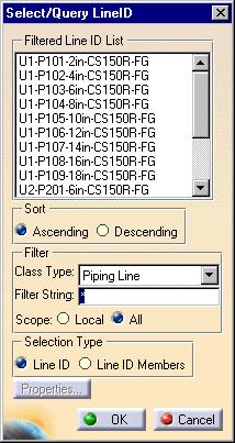
26 Querying a Line ID or its Members This task shows you how to query a line ID or its members. When you query a member you are asking which line ID it belongs to. When you query a line ID you are asking which members belong to it. 1. Click on the Select/Query Line ID button. The Select/Query Line ID dialog box opens. The lines displayed depend on your Scope selection - Local or All. 2. Use the Sort and Filter options if you need to. Under Filter, select the Local option if you only want to filter line IDs in the document. Select All if you want to filter all line IDs available to you. The Filter String field allows you to enter a line ID name - you can use wild cards. Clicking the Filter Attributes button brings up the Line Attribute Filter dialog box. See Select/Filter Line IDs to learn more about filtering.

27 3. To perform a query on a line ID click on the line ID in the Line ID list. The members of that line ID will be highlighted. To query a member click on it in the document. All members that belong to the same line ID will be highlighted and the line ID will be highlighted in the dialog box.

28 Select/Filter Line IDs This task shows you how to select a line ID or its members, and to filter for line IDs. Piping lines are used in the illustration below - the process is the same for other types of line. You can edit the properties of line IDs or their members after selecting them. You must make some setup changes if you want to see all properties of a line. See Displaying Line ID Properties in a Catalog to learn how to do it. 1. Click the Select/Query Line ID button. The Select/Query Line ID dialog box displays. 2. Use the Sort and Filter options if you need to. Under Filter, select the Local option if you only want to filter line IDs in the document. Select All if you want to filter all line IDs available to you. Use of the Filter Attributes button is explained below. 3. If you are selecting members then select Line ID Members under Selection Type. If you want to select a line ID then select Line ID.
29 4. Click to select a line ID in the Line ID list or click on one of the members. Either the line ID or the members will be selected, depending on the selection you made in Step Click the Filter Attributes button is you want to filter for line IDs. The Line Attribute Filter dialog box displays.
 or > (greater than). the operator *= means you are using a wild card.")
30 6. Click the drop down arrow in the Attributes field to select a property. Name is selected in the image above. Click the drop down arrow in the Operators field to select an operator. Most are obvious, such as == (equal to) or > (greater than). the operator *= means you are using a wild card. If you select this operator and enter U8 in the Values field then the function will filter for all lines beginning with U8. Select or enter a value in the Values field. This is the value that the function will filter for. Click Add when you have defined your query to add it to the Composed Query window. The And/Or buttons let you further refine your search. You can click the And button to add another query to your search. Clicking the Eraser button removes a query from the Composed Query window. The Filter String field allows you to enter a line ID name - you can use wild cards.

31 Transfer Members of a Line ID This task shows how to transfer members of one line ID to another line ID. 1. With your document open, click the Transfer Line ID button. The Transfer Members of Line IDs dialog box opens. The lines displayed depend on your Scope selection - Local or All. 2. Select the line ID to which you want to transfer a member. (When you select a line ID, all members that belong to it are highlighted.) 3. Click on the member that you want to transfer. It will be transferred to the line ID you had selected. 4. You can also use a feature called multi-select to transfer several members at a time. To do this:

32 5. Select the members you want to transfer by clicking and dragging. They will change color once they are selected. 6. Click on the Transfer Line ID button. The Transfer Members of Line IDs dialog box appears. 7. Select the line ID to which you want to transfer the members. You will be alerted that you are about to transfer the members. 8. Click OK. The members will be transferred. The line ID and member must be compatible for the transfer to take place. For instance, you cannot transfer a member of an I & C loop to a piping line. If you use the multi-select feature to include an incompatible member, it will not be transferred.
 3.")
33 Deleting a Line ID This task shows you how to delete a line ID. 1. Click the Delete Line ID button. The Delete Line ID dialog box displays. The lines displayed depend on your Scope selection - Local or All. 2. Select the line ID that you want to delete. (When you select a line ID all members that belong to it are highlighted.) 3. If the line ID you selected has members a message will display alerting you that all members belonging to that line ID will be deleted. 4. Click OK. The line ID and all its members will be deleted.
34 Only line IDs contained in your document will be deleted. The same line ID used in other documents will not be deleted unless you open those documents and follow the steps given above.

35 Renaming a Line ID This task shows you how to rename a line ID. This task requires that a project has been defined in Project Resource Management. 1. Click on the Rename Line ID button line IDs showing.. The Rename Line ID dialog box displays, with a list of 2. If you want to search for other line IDs scroll through the list or enter a keyword in the Filter String field.
36 3. Select the line ID you want to rename. The Rename dialog box displays. 4. The box will display a name in the Default ID field. This name is based on preferences set by your system administrator. To use this name click the Set to default button. To use a different name enter it in the ID field. Click OK. 5. Click OK again in the Rename Line ID box. The line ID will be renamed.
37 Modifying the Properties of a Line ID This task shows you how to modify the properties of a line ID. 1. With your document open, click the Select/Query Line ID button dialog box displays, showing the line IDs contained in your document.. The Select/Query Line ID 2. Select the line ID whose properties you want to modify. 3. Under Selection Type select Line ID. 4. Click the Properties button. The Properties dialog box will display. 5. Enter your changes and click OK.

38 Merging Line IDs This task shows you how to merge the members of one line ID into another line ID 1. With your document open, click the Merge Line IDs button displays showing all the line IDs contained in your document.. The Merge Line IDs dialog box

39 2. Select the line ID you want to merge. All members that belong to that line ID will be selected. The lower field will display the line IDs to which it can be merged. 3. Select the line ID you want to merge with and click OK. All members of the first line ID will merge into the line ID you selected, and the first line ID will be deleted. You cannot merge incompatible line IDs. Also, members of a line ID that is merged into another will assume the properties of the line ID into which they were merged.
40 Importing Line IDs This task shows how to import and/or update Piping Line IDs. The Import Line ID feature offers the user the utility of importing line IDs from existing databases in other CAD software products.the Update feature allows you to update the properties of existing line IDs with properties contained in an XML import file. Installation of the Document Type Definition (DTD) and knowledge of XML are prerequisite to using this feature. The file format for the Line ID XML Import File resides in the DTD. The location of the DTD and sample XML file is platform dependent. In Windows the path for the DTD is...\intel_a\startup\equipmentandsystems\piping\sampledata\plantshiplineidimport.dtd. For the XML file, the path is...\intel_a\startup\equipmentandsystems\piping\sampledata\pipinglineidimportsample.xml. The paths for the other platforms are identical with the exception of the platform identifier. Shown below are the platforms with their respective identifiers. Windows:...\intel_a\ AIX:.../aix_a/ HPUX:.../hpux_a/ IRIX:.../irix_a/ SOLARIS:.../solaris_a/ In all cases, copy the PlantShipLineIDImport.dtd and the PipingLineIDImportsample.xml file to a local directory with 'write access'. In the following scenario both the sample XML file and the DTD have been copied to a user Temp directory. A portion of the sample XML file is shown below:
 with properties of line IDs of the same name upon import.")
41 Be alert to any line IDs you have created as well as the line IDs you will be importing. The properties of existing line IDs will be updated (replaced) with properties of line IDs of the same name upon import. The path for your line IDs is preset under Project Resource Management. 1. Click the Import Line ID button.

42 2. The Line ID Import/Update dialog box opens. Click to open the file. This will cause the subroutine to run which will generate the line IDs from the XML file. Note that under Files of type, only XML files may be displayed and opened. 3. When the routine is complete, the Results Summary will display. 4. Click View output file to view the Line ID Import/Update Report for the sample case below.

43 5. You can verify that the new line IDs have been imported by clicking the Select/Query Line ID button. The Select/Query Line ID dialog box opens showing the updated and imported line IDs.
44
45 Placing Components This section discusses placing components, and placing nozzles on components. Placing component multiple times Placing a nozzle on a component
46 Placing a Component Multiple Times This task shows you how to place components several times. 1. Double-click on the Place Components button. The Catalog Browser displays. 2. Select the component you want to place by double clicking on it. 3. Move your pointer - the component moves with it - to the location where you want to place the component. 4. Click to place the component. The component will be placed and the Catalog Browser will remain displayed. 5. To place the same component again click at a new location. 6. To place a different component double click on it in the Catalog Browser and follow the procedure given above.

47 Placing a Nozzle on a Component This task shows how to place a nozzle onto a component. This method can also be used to attach other compatible components. 1. With the component on which you want to place a nozzle displayed, click on the Place Component button. The Catalog Browser displays. 2. Select the nozzle you want to place, move your pointer to the component and make sure it is selected. The nozzle will be placed on the nearest compatible connector when you click. In the image below the nozzle has attached itself to the nearest connector even though the pointer is not over the connector. A nozzle will only attach to a piping connector. It will not attach to an I & C connector.
48 Modify Object Properties This section explains ways of querying and editing the properties of objects. Objects refers to components, lines, etc. You can edit various properties of objects, such as flow capacity, etc. You can query an object to determine if its properties are derived from another object. Edit or Display Properties of an Object Filter the Properties of an Object Renaming Objects Propagate Object Properties

49 Edit, Display or Query the Properties of an Object This task shows you how to edit, display or query the properties of an object. 1. Select the component in your document. 2. Click Edit - Properties. The Properties dialog box appears with the properties displayed under various tabs. If the object cannot have derived values, the Derived checkboxes will not display. If a Derived checkbox is selected, it means the value is derived. If it is not checked the values are not derived. A value is considered to be derived when it is obtained from another object. For instance, a piping route may derive the values of some properties from the line ID of which it is a member. The Properties dialog box will display tabs, most of which are generic to all products. The Graphic tab allows you to change the looks. Under the Product tab you can make changes to the basic Product in the specifications tree, such as renaming. The Object tab displays information about the object such as ID, Function Class, Parent Group or Group Members, depending on the object being queried. See Infrastructure documentation (Basic Tasks - Manipulating Objects - Displaying and Editing Graphic Properties) and Product Structure documentation (User's Tasks - Modifying Component Properties) for more information. Specific to PID and HVAC Diagrams are the following tabs: piping, equipment, instrumentation and HVAC. They will display depending on the class of object whose properties you are editing. Click the More button if one of these tabs does not display, or if you want to see other tabs.

50 3. To query an object, select it from the tree or in the diagram. Right-click and select Properties from the pop-up menu or click Edit - Properties in the main menu and select Properties. Click the Object tab to view the properties of the object selected. In this example Parent Groups shows you the line ID of which the Blocking Valve is a member. 4. Enter values in the fields that are available and click OK. The properties will be edited. 5. You can override derived values by modifying the values as outlined in Step 3. The Derived checkbox will become unchecked. You can also override derived values by unchecking the Derived checkbox. To revert to derived values check the Derived checkbox. 6. Click OK to end. Some objects have discrete values - you can only select certain values. In that case you will be able to display a drop-down box and select one of the values in it.

51 Filter the Properties of an Object This task shows you how to filter the properties of an object displayed in the Properties dialog box. Filtering the properties means you can choose to display or hide any of the properties shown in the Properties dialog box. 1. Click the Filter button on the Properties dialog box (Edit or display properties of an object). The Attribute Filter box displays. 2. Click on each property to toggle between Display and Hide. An X next to a property means it is displayed. The settings will be retained when you open the Properties dialog box again.
; in this case, PipeFunction-004, indicating that this is the fourth instance of")
52 Renaming Objects This task shows you how to rename objects. 1. With your document open, select the object and click the Rename button. The Rename dialog box displays. In the view below you can see that the ID: field is displaying the name assigned by the application (the default name); in this case, PipeFunction-004, indicating that this is the fourth instance of a pipe function being placed in this document. 2. If you wish to rename the object (or instance) enter the new name in the ID field. To revert to the Default ID click on the Set to default button. 3. If you want to rename additional objects click Apply and continue renaming. 4. Click OK when finished. The objects will be renamed. Using this command to rename a component does not rename all instances of that object. If you have placed an object more than once in a document, and want to rename all of them, you will have to rename each one, individually.

53 Propagate Object Properties This task shows you how to propagate an attribute change using the Properties dialog box. This function allows you to propagate a change in size value throughout a network path with certain limitations. To propagate an attribute, e.g., nominal size, you must select an object in your document that has such an attribute. The attribute can be propagated when you see the Propagate button on either the Piping or Instrumentation tabs. See Rules below for details on the requirements and limitations of attribute propagation. 1. To select the component in your document whose attribute is to be propagated, right click the object in the specifications tree and select Properties from the menu. Alternatively, select the object and click Edit - Properties. 2. In the example below, the Properties dialog box is displayed with the Piping tab open and the Propagate button visible. In this case, we have a blocking valve placed on a 4 inch piping line.

54 3. In the Properties dialog box, use the drop down arrow in the Nominal Size field to change the value to 6 in. Click the Propagate button. The Attribute to Propagate dialog box opens showing the attributes that can be propagated. Click on Nominal Size. The objects in the propagate path for the attribute 'Nominal Size' will highlight. If a different attribute is then selected, the new path will highlight. 4. Click OK in the Attribute to Propagate dialog box to return to the Properties dialog box. Click Apply or OK. The nominal size of the valve will be overridden to 6 inches and all objects in the network with a 'nominal size' attribute will be changed to 6 in. See Rules, below, for requirements and limitations on propagating an attribute. Rules This function allows you to propagate a size value over a network path. Propagation may occur in all directions from the propagating object with the following exceptions which limit the extent of the "network": Objects of a different discipline than the propagating object. Objects with no nominal size, or equivalent size attribute. End of a network path (i.e., no connectivity). Off-sheet connectors. Branch to Main Route. Main Route to Branch. Object in a different logical line (Line ID). Nozzles. Reducers - one side is affected. Switching Valve (3-way) or a Switching Valve Function (4-way).
55 On and Off Sheet Connectors Creating and working with on and off sheet connectors is explained in this section. To learn how to store on/off sheet connectors in a catalog see Storing objects in a catalog. Place On and Off Sheet Connector Link/Unlink On and Off Sheet Connectors Query Connector for Linked Object
56 Placing On and Off Sheet Connectors This task shows you how to place on and off sheet connectors in a design. On and off sheet connectors are used when it is not practical to visually display all of a line on one sheet and a second sheet has to be used; or when design considerations require interrupting display of the line even if all of it is on one sheet. In such cases on and off sheet connectors are placed where display of the line ends, and at the point where it is displayed again, to show that the visual display was interrupted and the two halves should be regarded as one continuous line. To learn how to build a graphical representation of a connector see Building a graphic. 1. Click the Place On/Off Sheet Connectors button. The Catalog Browser displays. 2. Locate the connector symbol you want to use and click on it. 3. Move your pointer to the line where you want to place it. NOTE: When you click on the line the symbol will be placed at the closest open connection. You can also select a connector on the line to place the symbol. 4. Repeat the above steps and click on the second line on which you want to place it. The connector symbol will be placed. The image below shows on and off connector symbols placed at the ends of two lines. From Release 13, when you place an on/off sheet connector the application creates a publication that is visible in the specifications tree. In the image below it is the line PipeFunction-051,Piping Connector.2.CTR. The publication contains information about the connector. When you link the on/off sheet connector to another connector, that information will also be stored in the publications of both connectors. The publication does not identify the document - only the connector. Before this change, information about the connector (including about the document which contains it)
57 was stored in a different way and no publications were created.
58 Link/Unlink On and Off Sheet Connectors This task shows you how to link and unlink on and off sheet connectors. 1. To link, click the Link On/Off Sheet Connectors button. 2. Click the first connector you want to link. 3. Click the second connector. A link will be created between the two. NOTE: Each connector will be highlighted as you move your pointer over it. 4. To unlink connectors click on the Unlink On/Off Sheet Connectors button and click on one of the on or off sheet connectors.
 and click. 3.")
59 Query Connector for Linked Object This task shows you how to query an on or off sheet connector to determine which connector it is linked to. 1. Click the Query On/Off Sheet Connectors button. 2. Move the pointer to the connector you want to query (it will highlight) and click. 3. If the linked connector is in the same document a zoomed-in and highlighted image of the linked connector will be displayed. The image below is shown zoomed-out. The highlighted connector is the linked one. 4. If the linked connector is in an external document then the Query On/Off Sheet Connector Link dialog box will display.
60 5. The Document Name field lists the document (the document must be open) that has the connector to which the queried connector is linked. There may be more than one if a connector of the same name resides in more than one document. That can happen if you have made copies/versions of the document. The Linked to Publication field names the specific connector to which it is linked. The Reframe button lets you reframe the view on the linked connector. The Load button may become active if you are working with documents that were created before Release 13. If the Load button is active, click it to open the document that contains the linked connector.
61 General Design Modification Ways of making general design modifications are discussed here. Search for Objects in a Document Display Flow Arrows in Document Display Line Gaps in Document Connect Objects Disconnect Objects Measure Distance Between Objects Move Design Elements Align Objects Defining Frame Information

62 Search for Objects in a Document You can search for objects in a diagram by using the Edit - Search command. This will display the Search dialog box. Under Workbench select your workbench. Under Type select the type of object you are searching for. Detailed instructions on using the Search function can be found in the Infrastructure User Guide under Basic Tasks - Selecting Objects.
63 Display Flow Arrows in a Document This task shows you how to display or hide flow arrows in the entire document. 1. From the main menu, click View - Flow. 2. Select Show All Flow to display all flow arrows and NoShow All Flow to hide all flow arrows in the entire document. See also Display flow arrows on a line..
64 Display Line Gaps in Document This task shows you how to display or hide line gaps in the entire document. If you choose to display line gaps where one line crosses another it will appear that there is a gap - although there is no real break. If you hide line gaps, one line will appear to cross another, although there will be no connection between the two lines. 1. From the main menu, click View - Gaps. 2. Select Show All Gaps if you want all gaps to be displayed or Noshow All Gaps if you want to hide them.
65 Connect Objects This task shows you how to connect objects, that is components and routes. Two conditions must be met before objects can be connected: the objects should have available connectors (see note below), and the connectors should be compatible. Enabling dynamic connectors in a component allows for automatic creation of connectors during the design process. 1. Click the Connect button connect. and then select the connectors on the two objects that you want to 2. The second object will move to connect to the first, and the connector symbol will disappear, indicating that the two objects are connected. All connections of the second object are maintained. Each object will highlight as you move your pointer over it. If one or both objects do not highlight, it means that for some reason they are not compatible, or connectors are not available.
66 Disconnect Objects This task shows you how to disconnect objects. 1. Click on the Disconnect button. 2. Click on each of the two objects that you want to disconnect. The objects will be disconnected and the connector symbol will display.

67 Measure Distance Between Objects This task shows you how to measure distance between components. Distance will be measured in the working units you have set. You can measure the distance between components, between a component and run, or between run and run. In the case of components you have to select a connector, placement point or bounding box corner. In the case of a run you have to select node points that display on a run (when you move your pointer over the run), or connectors at the ends of runs. 1. With your document open click the Measure Tool button. The Measure dialog box displays. 2. You have three modes available to you. The first button - Measure Distance - measures directly between two objects. Click the button and move the pointer over the first component you want to measure from. The reference points on the component display - you need to select a reference point. Move the pointer to the second component and select a connector. The distance between the two
68 displays in the Measure dialog box. 3. The second button - Measure in Fan Mode - allows you to measure from a reference component to other components in your document. Click the button and click a connector on the first component. This component becomes the reference point. When you click a connector on a second component the Measure dialog box displays the distance between the two. When you click a third component the dialog box displays the distance between the reference component and the third component you just selected. The images below show the distance between the reference component and the valve, and the distance between the reference component and the pump. The dotted red lines display when you check the options (Show) in the Measure dialog box. 4. The third button - Measure in Chain Mode - allows you to measure from the last component you selected. Click the button and select a component, then select a second component. The Measure dialog box display the distance between the two. Now click a third component. The dialog box displays the distance between the second and third components.
69
70 Move Design Elements This task shows you how to move all or part of a design. You can use this command to move schematic objects, drawing objects and text. 1. With your document open use your mouse pointer (hold down the left button) to "draw" a square (trap box) around the portion you want to move. Those design elements are highlighted. 2. Click the Schematic Translate button location. and click and drag the selected portion to the desired
71 3. Click again when you have the location right. The selected portion will be moved with all connections maintained.
72 You can use the same process to move the entire design.
. The Align Component box prompts you to select the first object to align.")
73 Aligning Objects This task shows you how to align objects. You can align objects vertically or horizontally, and the former is explained here. 1. With your document open, click the Align Vertical button (for horizontal alignment click Align Horizontal). The Align Component box prompts you to select the first object to align. When you move your pointer over an object a dashed line displays, to help you select the exact location to align. When the option Use Placement Point is unchecked you can align using connectors or the edges of the bounding box. If you check the option then you will only be able to select the placement point.
74 2. Select the first alignment point, and move your pointer over the second object. A dashed line will not show but the points that you can select for alignment will display. Make your selection - the second object aligns to the first. All connections of the second object are maintained.

75 Defining Frame Information This task shows you how to define frame information. You can determine the position of a component in a frame using various methods, such as generating a report. Before you can do that, however, you have to enter information about the frame you are using. The process is described here. The information needs to be defined only once for each document. 1. Click Insert - Frame Information. The Frame Information dialog box displays. Select the corner of the frame from which to calculate. Enter a value for the horizontal spacing - any number you enter will be calculated in the current units selected. If you enter a single figure the grid will be calculated from that figure on. For instance, if you enter 1, and the units selected are inches, the grid lines will be spaced every one inch. If you enter two figures, such as 1,2 the grid will be spaced as one inch/two inch, repeated through the frame. Enter a letter or number for the horizontal grid. They are placed consecutively. You can use a comma delimited pattern also, such as A, B or AA, BB, which will be repeated through the grid. Enter a value for the vertical spacing - the same rules that apply to the horizontal spacing apply to this too. Enter a letter or numeral for the vertical grid - the same rules that apply to the horizontal spacing apply to this too. 2. Click OK.
76 Modifying a Component Ways of modifying a component are discussed in this section. Rotating a Component Flipping a Component in Free Space Flipping a Connected Component Changing the Scale of a Component Switch Graphic Representations Replacing a Component Delete/Unbuild a Component
77 Rotating a Component This task shows you how to rotate a component. A component can only be rotated if it is in free space - connected components cannot be rotated. 1. With your component displayed, click the Rotate Right or Rotate Left button. 2. Move the pointer to the component you want to rotate. If it can be rotated (if it is not connected) it will be selected when you move the pointer over it. 3. Click on the component to rotate it. It will rotate 90 degrees in the direction you selected. The image below shows a selected component and a component that has been rotated. Components can only be rotated in 90-degree increments.
78 Flipping a Component in Free Space This task shows you how to flip a component that is in free space. When a component flips in free space it rotates 180-degrees on the vertical or horizontal axis. The axis on which it will rotate is the X or Y axis as laid out when the component graphic was originally created. In the image below the component graphic was originally created with the Y axis running through the center and the X axis at the base. In the second image the Flip Horizontal command was used to flip it on the Y axis. In the last image the Flip Vertical command was used to make it flip on the X axis. 1. Click the Flip Horizontal or Flip Vertical button. Flip Horizontal will flip the component on its vertical axis. Flip Vertical will flip the component on its horizontal axis. 2. Click the component you want to flip. It will be flipped.
79 Flipping a Connected Component This task shows you how to flip a component that is connected. When a component is inline (connected) it will use the line in which it is placed as the axis on which to flip. 1. Click the Flip Inline button if you want the connections to remain as they were. Click the Flip Connections button if you want the connections to flip also. 2. Click the component. It will be flipped.
80 Changing the Scale of a Component This task shows you how to change the scale of a component. You can rescale any component in the diagram; and a component connected to another component can be resized. Only the selected component will be rescaled. For example, if you have a pump with a nozzle and you resize the pump, the nozzle will not be resized; however, it can be resized separately. 1. Click the Scale Component button. 2. Click on the component whose scale you want to change; or right-click on the component and select Scale from the drop-down menu. The Scale Component dialog box displays. 3. Enter a value in the Scaling Factor field. For instance, if you enter 2 it will double the size, if you enter.5 it will halve the size. In addition to the rescaling methods described above, you can resize manually by clicking on the component and dragging one of the corner 'handles' to set the size. Bring up the Scale Component window again and the Scaling Factor will reflect the new size. 4. Click OK. The scale of the component will change.

81 Switching Graphic Representations This task shows you how to switch graphic representations of a component. You define multiple graphic representations of a component when you need to show more than one version of the same component. For instance, you may need to show a valve in an open position, closed position and three-quarters closed position. Creating these three versions of the same component allows you to place any one of these. To learn how to define graphic representations see Define multiple representations of a component. 1. Right click on the component that you want to replace with a graphic representation. A pop-up menu displays.

82 2. Click Swap Graphic. The Swap Graphic box displays. In the image below, the box shows that the component has one graphic representation associated with it. 3. Select the representation that you want to replace the component with and click Close. The component will be replaced.
83 Replacing a Component This task shows you how to replace one component with another in a schematic diagram. It uses piping components to explain the task, but the procedure is the same for other types of components. When replacing components in a diagram, certain conditions for, and consequences of, replacement must be taken into consideration. Connections - Using the Replace Component feature will connect all compatible connectors of the new component with the objects originally connected to the old component based on compatibility and proximity criteria as follows: For each compatible connector on the new component, the closest compatible connector of one of the objects originally connected to the old component will be connected until all the connectors on the new component have been used. Attributes - All attributes on the old component will be lost. The replace command will not attempt to copy them to the new component. Component Instance Name - A new component name will be generated in the specifications tree for the new component. Annotation Links - All annotation links of the old component will be lost. The replace feature will not attempt to copy them to the new component. Graphical Representation - The primary graphical representation of the new component will be used. Flow - Flow reality, the same as that used in component placement, will be checked as part of the compatibility checking (above). Orientation For unconnected component - applies the orientation matrix of the old component on the new component. For connected component - applies the orientation matrix of the old component to the new component and finds the closest connector (in distance) on one of the originally connected objects. Performs a component placement on the connector found. 1. With your document open, select the component in the schematic you want to replace and click the Replace Component button.

84 2. The Catalog Browser will open. 3. Select the component from the Catalog Browser. In this case we have replaced a blocking valve with a metering valve.
85
86 Delete/Unbuild a Component This task shows you how to "unbuild" or "deconstruct" a component. When you unbuild a component you to "untype" it - remove the subclass, connectors and flow path that define the component. All you are left with is the geometry. This allows you to reuse the geometry to build another component. To unbuild a component right-click on it and select Delete in the drop down menu that shows A message will ask if you want to delete the reference component. Click OK. You will be left with the geometry only. Repeat the process to delete the geometry also.
87 Modifying a Route Methods of modifying routes are discussed in this section. Setting Graphic Properties of a Line Adjust the Position of a Segment Move the Extremity of a Route Lock or Unlock a Route Breaking a Route Connecting Two Routes Set the Flow Direction of a Route Display Flow Arrows on a Line
88 Setting Graphic Properties of a Line. This task shows you how to set the graphic properties of a line. The "looks" of any line that you route are governed by a style called the "curve" style, which is provided with this application. Whenever you enter the Route command you will only have access to this style in the Style toolbar. 1. To override the properties of the curve style, select line color, line thickness, etc. in the Graphic Properties toolbar. These properties will stay selected until you change the style in the Style toolbar. For instance, if you exit the Route command during a session, the style selected in the Style toolbar changes and the properties you selected earlier will no longer be available when you re-enter the Route command. 2. You can modify the properties of the default curve style provided with this application. To learn how to change the properties of a style please see the Interactive Drafting user manual.
89 Adjust the Position of a Segment. This task shows you how to adjust the position of a segment in a line route. A segment can only be adjusted if it has at least one other segment on either side. 1. Select the line in which you want to move a segment. The route will be highlighted and a manipulator will display on all segments that can be adjusted. 2. Click and drag to adjust the segment.
90 You cannot adjust a segment past the end points of the route. Nor can you adjust it past a branch.
91 Move the Extremity of a Route This task shows how to move or stretch the extremity of a route. 1. Click on the segment whose extremity you want to move or stretch. The segment will highlight. 2. Click and drag the connector symbol at the end of the section and reposition it. The image below shows a route, a route with a section selected, and the repositioned extremity.
92 Lock or Unlock a Route This task shows how to lock or unlock the path of a route. After you 'lock' a route you can move its extremities without altering the path of the rest of the route. Only the last segments at both ends of a route can be manipulated when it is locked. 1. To lock a route, right click on it and, in the drop down menu that displays, select Lock Route. In the first route below the user has locked the route and moved an extremity without affecting the path of the rest of the route. The second route has not been locked and its path has changed as the user moves the extremity. 2. To unlock a route, right click on it and, in the drop down menu that displays, select Unlock Route.
93 Breaking a Route This task shows you how to break a route. 1. Click the Break Route button. 2. Click the route you want to break at the point where you want it broken. The route will be broken and a connector symbol will appear. The route has been broken into two and you can move it if needed, as shown in the image below. If the Snap To Grid function is turned on, the line will break at the grid line that is closest to the point where you clicked.
94 Connecting Two Routes This task shows you how to connect two routes. 1. Click the Close Route button. 2. Click each of the two routes that you want to connect. The routes will be connected and the connector symbol will disappear. For this function to work the connectors on the two routes must be compatible and must be at the same location.

95 Set the Flow Direction of a Route This task shows you how to set the flow direction of a route. 1. Click on the Flow Direction button. The Flow Direction box appears. 2. Select Individual Line Function or All Line Functions in Line ID. If you select Individual Line Function then you will be able to set the flow direction of a section of the route between two components. If you select All Line Functions in Line ID, you will be able to set the flow direction of the entire route. In the image below Individual Line Function was selected. In the following image All Line Functions in Line ID was selected.
96 3. Click on the route to toggle between three flow directions. The three directions are as shown in the image below. If the flow arrows are not displayed then on the first click they will be displayed. If they are already displayed then the first click will change direction. If there is more than one flow direction in a route, then the flow direction of each will change independently.
97 Display Flow Arrows on a Route This task shows you how to display or hide flow arrows on a route. 1. Click on the Flow Show button. 2. Click on the route. If arrows are not showing they will show. If arrows are showing they will be hidden. You can right-click on a route and select from the pop-up menu to perform the same function. See also Display flow arrows in a document.
98 Creating and Managing Zones This section discusses creating and managing zones. Creating a Zone Creating a Boundary Modifying a Boundary Updating a Boundary Querying a Zone Modifying the Properties of a Zone Delete/Rename a Zone
99 Creating a Zone This task shows you how to create a zone ID. A zone ID is used to identify and assign properties to a group of objects. You define a zone ID by creating boundaries which enclose the group of objects. In the illustration below the user has drawn a circle around some lines and components. The circle defines the boundary which becomes part of the zone. When you assign certain properties to the zone they will also be assigned to the objects within the boundaries of the zone. A zone ID can extend over several documents and contain numerous boundaries. While a zone ID can extend to multiple documents, once you create a boundary, it becomes local, or specific to that document. When you change the boundaries of the zone ID you do it locally so that the change applies to a specific document. Before you create zones you must designate a directory in which they will be stored. See Understanding Project Resource Management. 1. Click on the Create Zone button. The Create Zone dialog box displays.

100 2. Enter the name for your new zone in the Zone ID field and click on Zone in the Class Viewer. You can accept the default name by clicking Set to default. 3. Click the Properties button to enter properties if you want to. Certain default properties will be assigned but you can enter your own if you want to. 4. Click OK. The zone will be created.
101 Creating a Boundary This task shows you how to create a boundary. Boundaries are used to enclose groups of objects, and are parts of zones. In the illustration below the user has drawn a square around some lines and components. That square can be designated a boundary and made part of a zone. 1. Use one of the Sketcher functions to enclose the objects that you want to include in the boundary. The objects must be fully enclosed within the boundary. You will not be able to create the boundary if there is a gap in it. 2. Click on the Define Zone Boundaries button display, listing all the available zones.. The Add Boundary to Zone dialog box will

102 3. Use the Filter/Sort button if you want to filter the available zones. If you want to create a new zone click the New ID button. 4. Select the zone under which you want your boundary and then select each line that constitutes the boundary. In the illustration above you would select all four lines that make up the square. The lines will change color as you select them. You can select any line to begin with. But after that each line you select must be connected to an already selected line. In the illustration above you cannot select the lower horizontal line and then the upper horizontal line. If you select a horizontal line you must select one of the vertical lines after that. 5. Click OK. The boundary will become a part of the zone.
103 Modifying a Boundary This task shows you how to modify a boundary. 1. In the illustration below the user has a boundary which he wants to extend to include more components. 2. Use the Sketcher function to modify the boundary. 3. Click on the Create Zone Boundaries button to bring up the Create Boundaries dialog box and then select the boundary you have modified. The boundary will be highlighted. 4. Click OK to modify the boundary.
104 5. If you add any new boundary elements to the boundary, as in the example below, only elements that existed originally will be highlighted. To modify the boundary select one of the preexisting elements and then each of the new ones. Click OK. If you extend preexisting boundary elements to include new objects they will be included in that boundary. However, if new objects are included when you modify the boundary by adding new boundary elements, you must use the Update function to include them in that boundary.
105 Updating a Boundary This task shows you how to update a zone boundary. You need to update a boundary when you add objects to the boundary or when you remove objects from it. If, for instance, you move an object outside a boundary but do not use the update function, the boundary will continue to count that object as part of it. In the illustration below the user wants to move the object that is outside into the boundary. 1. Drag the object into the boundary. 2. Click the Update Zones button. The boundary will be updated and a message box will display.
106 Querying a Zone This task shows you how to query a zone for its members, or query a member to see which zone it belongs to. 1. With your document open click the Select/Query Zone button box will display.. The Selecting Zones dialog

107 2. Check Local under Scope if you want to see all zones in the document. Check All if you want to see all zones available to you. 3. Use the Filter and Sort functions as needed. 4. To see which zone the boundary is part of, check Zone ID under Selection Type and click on the boundary. The zone will highlight. When you click on the zone all boundaries that are part of it will highlight. 5. To see which objects are part of the zone check Zone ID Members and then click on the zone.
108 Modifying the Properties of a Zone This task shows you how to modify the properties of a zone. 1. Click on the Select/Query Zone button. The Select/Query Zone dialog box will display. 2. Select the zone whose properties you want to modify and click on the Properties button. The Properties dialog box will display. 3. Enter your changes and click OK.

109 Delete/Rename a Zone This task shows you how to delete or rename a zone. 1. To delete a zone click on the Delete Zone button. The Deleting Zones dialog box will display. 2. Select the zone you want to delete and click Delete. The zone and all its members will be deleted. 3. To rename a zone click the Rename Zone button. The Renaming Zones dialog box will display.

110 4. Select the zone you want to rename. The Rename dialog box will open. 5. Enter the new name or Set to default and click OK. The zone will be renamed.
111 Annotating Diagrams This section explains the basic methods for annotating a diagram. Creating a Standard Annotation Create an Annotation with an Attribute Link Editing Annotation on a Placed Component
112 Creating a Standard Annotation Use the Text command in the Drafting toolbar to add annotations to your diagram. Click the Text button and click on the drawing where you want to place the text. Instructions for using the Text command, and other commands in the Drafting toolbar, are available in the Drafting documentation. Drafting toolbar

113 Create an Annotation with an Attribute Link This task shows you how to create an annotation with an attribute link. Piping objects are used to illustrate this function. The process is the same for other types of objects. It is recommended that instead of using this function, you use the newer, more flexible, functionality explained in Creating Text Templates. When you create an annotation with an attribute link, you are associating the annotation in the diagram with one or more attributes or properties of the component. When the value of a linked attribute is changed the annotation is updated automatically. If you create the attribute link on a placed component, the value in the annotation will change whenever the attribute value of the reference component changes. You can also add the annotation to a reference component, in which case it will display on all placed components (you can create additional annotations on the placed component). In this case, placed components will inherit attribute values from the reference component. If you want each placed component to have unique values, derived from the design document in which it is placed, then you must take an additional step. Right click on the text in the reference component (as shown in Step 3 or 4 below) and, in the drop down menu that displays, select Modifiable in Instance. See Editing Annotation on a Placed Component for more information. 1. Click the Text button and click on the drawing where you want to place the text. The Text Editor dialog box displays and a text box appears where you clicked. Enter the text in the Text Editor dialog box - it will display in the text box. Right click on the green border of the text box. It will turn red and and a drop down menu will display - select Attribute Link.


114 2. Select the valve in your document. The Attribute Link dialog box opens and displays a list of attributes. Scroll down the Attribute List to NominalSize and select it. 3. The nominal size will be appear in the Nominal size field in your text box. 4. Repeat the process and add an annotation for Piping Spec. Click on the line this time and select the attribute for the Piping Specification in the Attribute Link Panel. The annotation will show the specification associated with the Line ID. 5. Now, right click on the piping line in the document (or in the specification tree) and bring up the Properties dialog box. Change the specification to CS300 and click OK. The annotation for Piping Spec will be updated.
115 You should take note of the following behavior: If you place an annotation on an instance, with an attribute link that points to an attribute on the reference component (or object), and When you delete that instance, the annotation will not be deleted, unless It is the last instance of a component in the design document. If it is the last instance of a component then the annotation will also be deleted. If it is the last instance of a route it will not be deleted. To help you recognize an attribute on a reference component: In Step 2 above, all attributes that are preceded by the words Block Valve Function1 are attributes of the reference component. All others are attributes of the instance.

116 Editing Annotation on a Placed Component This task explains how you can edit the text on each instance of a component. This function lets you add different text on each instance of a component. It is best done when you are building a component. 1. Create the component, then click the Text button in the Drafting toolbar, and select the component, to add text. The Text Editor dialog box displays. 2. Enter your text and click OK. The text displays below the component - you can change the position if you want to by dragging. 3. Right click on the text and, in the drop down menu that displays, select Modifiable in Instance. You can now add different text to each instance of the component that you place. The text can be modified in a design document at any time - double click on the text to display the Text Editor dialog box, and enter your modification.
117 Building New Components This section explains building new components and storing them, adding connectors and defining flow paths. See the Infrastructure documentation (Advanced Tasks - Using Catalogs) for more information on creating catalogs and adding components to catalogs. Building a Graphic Create a Component with Specified Type Define Connectors on a Component Defining Dynamic Connectors Define Flow Path on a Component Define Multiple Representations of a Component Storing objects in a catalog
118 Building a Graphic This task shows you how to create a graphic. You need to have a graphical representation of a component before you can build the component. You also need to create a graphic to use as an on/off sheet connector. 1. Click the New Detail Sheet button. A detail sheet is created. 2. Click the New View button and then click in the detail sheet. A detail view is created in the sheet. The detail view is where you will build the graphic. 3. Click on one of the drafting tools, such as Line, to build the graphic. In the image below a valve has been created. When building a graphic for a component that is to be placed inline, you must place the center of the graphic at the origin, as shown in the image above. The same methodology is used to build an on/off sheet connector. To ensure that an on/off sheet connector can be placed correctly you should start building it at the origin and proceed in the positive X direction, as shown in the image below. To add a component or an on/off sheet connector to a catalog see Storing objects in a catalog.

119 Create a Component with Specified Function Type This task shows you how to create a component and specify a function type for it. To learn how to build a graphic see Building a Graphic. 1. With your graphic displayed, click on the Build Component button dialog box displays.. The Build Component 2. Double-click on the main functions to expand them. In the image above PipingPartFunction has been expanded.
120 3. Click to select one of the function types and then click on the graphic. The graphic will highlight. 4. Enter a name for the component in the Component Name field. 5. Click OK. The component is created.

121 Define Connectors on a Component This task shows how to add static connectors to a component. Dynamic connectors are explained in Defining Dynamic Connectors. 1. Click the Build Connector button and then click the component to which you want to add connectors. The Build Connector box displays. 2. Click the Static tab and select a connector type in the Build Connector box. Selecting the Show Connector Names checkbox will display the connector name during routing, when you move the pointer over the connector. Naming of connectors is essential when Auto-Routing in schematic driven 3D design applications such as Piping Design. Provided that the connector names are the same in both the 2D and 3D applications, the from-to connectors will be readily apparent and Auto-Routing will occur. 3. Click on the component at the point where you want a connector. The connector vector display appears with a default name for the connector type you selected. To reposition the name, click and drag it to the desired position.


122 4. To assign a more specific name to the connector, right-click on the default name or on the connector to bring up the contextual menu and select Rename. The Name Connector dialog box appears. Select a connector name, e.g., Inlet1, and click OK. 5. Click on one of the arrows to define a directional vector for the connector. One of the arrows will be selected by default. The directional vector establishes the angle at which another connector will attach. 6. To establish the flow capability or flow direction of the connector right-click on the connector. A popup menu appears. Move the pointer to Flow Capability and another menu offers the options: None, In, Out, In/Out. Select one by clicking on it. 7. Add more connectors by clicking on the component. 8. Click Close on the Build Connector box to end. The connectors will be added. To see the connectors again click on the Build Connector button and then on the component. To delete a connector right-click on the connector and then click Delete in the pop-up menu that displays.
123

124 Defining Dynamic Connectors This task shows how to enable dynamic connectors on a component. Enabling dynamic connectors allows for automatic creation of connectors during the design process. During some functions, such as routing or connect, connectors will be created when you click on the component. 1. Click the Build Connector button and then click the component to which you want to add connectors. The Build Connector box displays, showing connector types that can be placed on the component. 2. Click the Dynamic tab and select a connector type in the Build Connector box. You can select as many types as you need. An X appears next to a type that has been selected. Clicking Select All will select all connector types; Clear All will clear all selections. 3. Click Close to enable dynamic connectors.

125 4. The component below has four static connectors. It also has dynamic connectors enabled. Below you can see the dynamic connector that the user can create during the routing process. Once you have created a dynamic connector you can create flow, rename etc. - everything you can do with a static connector. To be able to do this an option must be enabled. Click Tools - Options, select Equipment & Systems and the Diagrams tab, and check the Modify Dynamic Connectors checkbox. See Define Connectors on a Component to learn more about connector creation.


126 Define Flow Path on a Component This task shows you how to create a flow path between the connectors on a component. Creating a flow path only creates a flow connection between connectors. It does not define the direction of flow, which is normally added later in the design process. 1. Click on the Build Internal Flow button and then on the component. The connectors on the component are numbered and displayed, and the Create Flow Path dialog box is displayed. 2. Click on the connectors between which you want a flow path. The connectors will be highlighted as you click on them and the flow path will display. At the same time, the two connectors between which there is a flow path will appear in the Create Flow Path box. 3. To end click Close. 4. To delete a connection, bring up the Create Flow Path box, select the connectors you want to delete, and click Delete.
127

128 Define Multiple Representations of a Component This task shows how you can define multiple graphic representations of a component. You define multiple graphic representations of a component when you need to show more than one version of the same component. For instance, you may need to show a valve in an open position, closed position and three-quarters closed position. Creating these three versions of the same component allows you to place any one of these. The example below assumes you have built a component and a graphic (see Building a component and Building a graphic) that you want to use as a representation of the component. 1. Click the Build Graphic button and then click the component for which you want to create a representation. The Build Graphic dialog box displays. The image below shows the component on the left, the graphic which you want to define as a graphic representation, and the Build Graphic box. 2. The Build Graphic box shows a list of graphic representation names you can use. Select one and click on the graphic. The Defined value changes to Yes in the Build Graphic box. 3. Click Close. The graphic is defined as a representation of the component a_valve. 4. To disassociate a graphic from a component bring up the Build Graphic box, select the graphic and click on the Remove button. You cannot define another component as a graphic representation. You must build a graphic to use as a graphic representation. You can define a graphic representation of a component that is in the catalog. To do so you must open the CATProduct document where catalog components are stored, create one or more graphics in the document, and follow the steps above.
 for information on creating and working with catalogs. 1.")
129 Storing Objects in a Catalog This task shows you how to store objects such as components and on/off sheet connectors in a catalog. Only basic information is supplied in this task. See the Infrastructure documentation (Advanced Tasks - Using Catalogs) for information on creating and working with catalogs. 1. With the component you want to store in the catalog displayed, click Infrastructure - Catalog Editor in the Start menu to create a new catalog. To open an existing catalog use the File - Open command and navigate to the catalog. The Catalog Editor opens. 2. Click Windows - Tile Horizontally so that both the Catalog Editor and the component are displayed. 3. Double click the family under which you want to add the component. You will need to add a family if this is a new catalog document. 4. Click the Add Component button. The Description Definition dialog box displays.
. This will allow an iconized image of the component to be displayed in the Catalog Browser. 7.")
130 5. Enter (or change) the name for the component. Add other information as needed then click the Select external feature button. 6. Click the Preview tab and select the option Local preview (stored in catalog). This will allow an iconized image of the component to be displayed in the Catalog Browser. 7. Click on the component you want to add to the catalog. The component will be added.
131 Analyzing Networks This section discusses ways of analyzing networks. Analyze Network for Connections Viewing Related Objects

132 Analyze Network for Connections This task shows you how to analyze a network for connections. This function will show you all objects connected to any selected object. You can also use it to view all possible paths between two selected objects. 1. To see all objects connected to any selected object, click Analyze - Networks in the menu bar, with your document open. 2. Select the Network tab and then select the object whose connections you want to see. The entire network will highlight and the Analyze Networks box will display the number of objects there are in the network.
133

134 3. To see all possible paths between two objects click the Path tab in the Analyze Networks box, then click the two objects. If there is a path between the two objects, it will highlight. If there are two or more possible paths, the Current Path field in the Analyze Networks box will display how many paths there are when you click on the down arrow. To see another path (if there is one) select it in the Current Path field.
135 Viewing Related Objects This task shows you how to view all the objects related to a selected object. "Related" refers to objects that are directly connected, as well as objects that are an organizational element, such as line IDs. The following describes this function in the Piping and Instrumentation Diagrams application; however the feature operates identically in the HVAC, Tubing and Waveguide Diagrams applications. To use this function properly you must disable the Automatic Expand option for the specifications tree. To do this click Tools - Options, go to General - Display and then the Tree tab, and uncheck Automatic Expand. 1. With your document open, click Analyze - Related Objects in the menu bar. The Current Selection Panel will display (see below). 2. Make sure the View related objects option is checked, and select the object whose relatives you want to see. All objects related to the selected object will display in the Current Selection Panel. In the illustration below the user has selected a valve. The Current Selection Panel display shows that the Check Valve is related to two others, Pipe Function.3 and Pipe Function.2, and is a member of line ID, PipeLine01.
136 3. You can also select one of the related objects shown in the Current Selection Panel; in this case Pipe Function. 3 or Pipe Function.2, to see which objects they are related to. 4. If you check Reframe on selection and then click on one of the objects in the Current Selection Panel, the object will display in your screen even if it was not currently showing. 5. Checking the Freeze box will freeze the contents of the Current Selection Panel and it will no longer be updated.
137 Performing Checks and Applying Design Rules This section discusses checking a document for design errors and applying design rules to a document. You need to have the product Knowledgeware in order to use these functions fully. However, a sample file is provided with this application with several checks and design rules incorporated. If you use this file to create your documents you do not have to obtain Knowledgeware in order to use these functions. But if you do not have Knowledgeware you will not be able to create new checks or new design rules, you will not be able to edit them and you will not be able to import checks and rules into a document. Enough documentation is provided here to enable you to use the sample file. However, to be able to use all Knowledgeware function you need to refer to the documentation for that product. Before you can use this function you must make sure the settings are correct. Click Tools - Options - General - Parameters and Measure and click on the Language tab. Under Language check Load extended language libraries. Either check All Packages, or uncheck this option and load the packages you will be using. A second setting you must make sure of is: Click Tools - Options - Infrastructure and click the Tree Customization tab. Activate Parameters and Relations. Using Knowledgeware Packages Importing Checks from Knowledgeware Opening a Sample Document Checking a Document for Design Errors Applying Design Rules to a Document Computed Attributes (2-D)

138 Using Knowledgeware Packages This task shows you how to load and use Knowledgeware packages (may also be known as dictionaries). You should see Knowledgeware documentation if you want to learn more about it. Knowledgeware provides certain functions that are used by all applications. In search and report definition functions, for instance, it allows users the capability of searching for objects, or defining how a report should be structured. This is achieved by 'exposing' objects and their attributes in Knowledgeware through the use of what are known as packages. A package is specific to an application or group of applications, and contains a list of objects and their attributes that have been exposed. The PlantShipLayout package, for instance, contains objects and attributes that are used by several applications, whereas the PipingLayout package contains the list of objects and attributes for piping applications. These packages must be loaded before you can use certain functions. There is a setting you must enable before you can load and use these packages. 1. Click Tools - Options - General - Parameters and Measure and click on the Language tab. Under Language check Load extended language libraries. Either check All Packages, or uncheck this option and load the packages you will be using. 2. If you check All Packages then packages for all applications - including many you do not need - will be loaded, and may slow operations. You may instead want to load selected packages.

139 3. There are several ways in which you can view the contents of each package. One way is to open the Knowledge Expert workbench, click the Expert Check button and click OK in the Check Editor dialog box to display the Check Editor: XXXX dialog box. Click the Browser button to display the browser. This displays packages in the left column, objects in the middle column, and attributes (and programs) of the selected object in the third column. Check the Show Inherited Attributes checkbox if you need to. 4. Following is a list of packages used by Equipment & Systems applications: PlantShipLayout - Several applications, should always be loaded. ProductPackage - All applications, should always be loaded. CompAccessLayout - Compartment & Access ElectricalShipbuilding - 2D electrical Conduitlayout - Raceway & Conduit Design EquipLayout - Equipment Arrangement HangerLayout - Hanger Design HVACLayout - HVAC applications InstrLayout - Several applications PipingLayout - Piping applications PlantArrangement - Plant layout RacewayLayout - Raceway & Conduit Design TubingLayout - Tubing applications WaveguideLayout - Waveguide applications
140
141 Importing Checks and Rules from Knowledgeware This task shows you how to import checks (and rules) from Knowledgeware into your document. Obviously, you must have Knowledgeware installed to do so. Before you can use this function you must make sure the settings are correct. Click Tools - Options - General - Parameters and Measure and click on the Language tab. Under Language check Load extended language libraries. Either check All Packages, or uncheck this option and load the packages you will be using. A second setting you must make sure of is: Click Tools - Options - Infrastructure and click the Tree Customization tab. Activate Parameters and Relations. 1. With your document open, make the root object in the specifications tree active, and then click Start - Infrastructure - Knowledge Expert. The application will open and you will see new entries in the specifications tree. Now you have to import the sample checks and rules provided with this application. 2. Click the Insert Rules button. The Load Report box will display. Navigate to the directory where the sample files are stored and import the files for the application you are running. The default directory and files you need to import are listed below: For 3-D products like Piping Design:...intel_a\startup\EquipmentAndSystems\MultiDiscipline\SampleData Import the following files for Piping Design, HVAC Design and Tubing Design: PhysicalPartsConnectivityCheck.CATProduct PhysicalPartsInconsistentNameCheck.CATProduct For diagrams products: intel_a\startup\equipmentandsystems\your_application\designrules. For Piping & Instrumentation Diagrams, import PipingDiagramChecks.CATProduct and PipingDiagramRules.CATProduct. For HVAC Diagrams, import HVACDiagramChecks.CATProduct and HVACDiagramRules.CATProduct. For Waveguide Diagrams, import WaveguideDiagramChecks.CATProduct and WaveguideDiagramRules.CATProduct. For Tubing Diagrams, import TubingDiagramChecks.CATProduct and TubingDiagramRules.CATProduct.

142 3. The checks and rules you have imported will display in the specifications tree. 4. Double click on the root product in the specifications tree to exit Knowledgeware and return to your workbench.

143 Opening a Sample Document This task shows you how to open the sample documents provided with this application. The sample documents have some checks and rules incorporated and you can use them without having Knowledgeware. 1.Click File - Open. The File Selection box will open. 2.Navigate to the directory where the sample files for the application you are running are stored by default. For diagrams products: intel_a\startup\equipmentandsystems\your_application\designrules. For 3-D products:...intel_a\startup\equipmentandsystems\multidiscipline\sampledata 3.See Importing Checks and Rules from Knowledgeware for a list of sample files. 4.When you open one of these document a message will display warning you that the file is Read Only. Click OK on the message box. The sample file will open with all the checks and rules displayed in the specifications tree. 5.Make your changes and then use the File - Save As function to save the file and give it a new name.

144 Checking a Document for Design Errors This task shows you how to check a document for design errors. This function allows you to check the entire document for certain errors, such as unconnected elements. The full list of errors for which you can check is given below. The procedure is the same whether you have Knowledgeware installed, or you are using the sample files provided with this application. 1. With your document open, right click on the entry RuleBase in the specifications tree. In the drop down menu that displays, select RuleBase object. In the sub-menu that displays select Manual Complete Solve. Your document will be checked for design errors.

145 2. The checks which came up with errors will have a red button against them. The checks that had no errors will have a green button. In the image below the check Unconnected Elements failed, which means there is one or more element in your document that is not connected to anything. 3. To see which elements failed the check, right click on the check, in this case UnconnectedElem. In the drop down box that displays select UnconnectedElem object. In the sub-menu that shows select Highlight Failed Components. The failed elements will be highlighted in the specifications tree. Some elements will also highlight in the viewer. 4. For diagrams products you can check for the following errors using the sample file provided with this application: General Design Checks have the following in addition to unconnected elements: Unconnected Coincident Element: Elements and connectors can be coincident, or occupying the same space, but not be connected to each other. Unconnected On/Off Sheet: On/Off sheet connectors in your document that are not linked to other documents. Flow Direction Conflict: Flow direction is not consistent in linked elements. Invalid Zone Boundary: A zone has a gap in the boundary. Invalid Part Type: Part type selected has invalid attributes. Invalid Part Number: Part type is incompatible with defined function. Undefined Part Number: No part number assigned. Other checks are: Inconsistent Name Check: This application employs a naming convention. This error means that an element has been named in violation of the rules defined by you. Inconsistent Nominal Size: This signifies that elements of different nominal size have been connected. Inconsistent Pipe Spec Check: This signifies that elements with different specifications have been connected.
146 Inconsistent Equiv Diameter Check: Ducts of different equivalent diameter have been connected. Out of Pipe Spec (for piping part functions only): Pipe specification is not derived from the line. Out of Duct Spec: Duct specification is not derived from the line. For 3-D products you can perform the inconsistent name and unconnected element checks.
147 Applying Design Rules to a Document This task discusses the application of design rules to a document. Intelligent design rules are incorporated in this application and certain changes will occur in your document even though you did not directly invoke them. You should know what these design changes are and why they are taking place. They are discussed below. Design rules will only be in effect if you have Knowledgeware installed and have imported rules into your document, or if you are using the sample file provided with this application. You can modify or create your own rules if you have Knowledgeware. Design rules are used to ensure that the graphics used in your document match the properties assigned to them. You may, for instance, have more than one graphic representation for a valve - two common representations are for closed and open valves. Suppose you have a valve in your document whose property is "open." If you change the property to "closed", the application will replace the "open" valve graphic with a "closed" valve graphic. The image below shows an open valve and a closed valve. If you change the property of the open valve to closed, the design rule will go into effect and replace the open image with a closed one. These changes will only occur if you have graphic representations defined for various properties. If you do not have graphics defined then nothing will happen. Various graphic representations for some components are provided with this application. The Piping Valve Position rule, described above, also checks for part type and will select the correct graphic for the defined part type. the following rules are provided with the sample document. Instrument Location Rule: This rule will change the graphic of instruments based on their location. The components affected are those under P & ID Instruments in the Catalog Browser (in the sample documents provided). The rule applies to the object class, Instrument_Part_Function and the property, Instrument Location. Pipe Function Line Category: The rule will change the appearance of lines (color, thickness and style) based on the properties major and minor. The object class affected is Pipe functions. I & C Line Signal Medium: The line style of I & C lines will change depending on the type of signal for which you set the property Signal Medium, e.g. data or hydraulic, etc. The object class is Instrument_I&C line_function. HVAC Valve Position: This rule applies to open and closed valve positions of HVAC valves. Waveguide Line Shape: The line style of waveguide lines will change depending on the value assigned to the attribute Shape (e.g. round or rectangular). The object class is Waveguide_Line_Function.
148
149 Computed Attributes (2-D) A list of "computed" attributes is given here. Computed attributes are so called because their values are computed by the application from other data. All objects have certain attributes, such as nominal size. These attributes are either created by users through the Feature Dictionary, or are provided to users in the sample CATfct file that comes with the application (see Feature Dictionary documentation). There are certain other attributes that are not included in the CATfct file but are nevertheless available to users. Users can define checks and rules with them, or use them in ATS tags (if they have Knowledgeware installed). These attributes also display when using the edit-search or reports functions. A list of these attributes, with their meanings, is given below. 1. ClassName: The class name of the object, if there is one. PartType: The part type of the object as set through the Part Selection command. PhysicalPartNumber: The catalog part number of the physical device that realizes the schematic object. ParentPipingLineName: The name of the piping line of which the object is a member. ParentICLoopName: The name of the I & C loop of which the object is a member. FromToTable: A list of the objects that are members of a line, between two selected points. Other piping lines that join the selected line are also included. ConnectedEquipmentName: The equipment to which a nozzle is connected. OnOffSheetDocLinkName: The name of the document that an On/Off Sheet connector is linked to, if any. ParentHVACLineName: The name of the HVAC line of which the object is a member. ParentTubingLineName: The name of the tubing line of which the object is a member. ParentWaveguideLineName: The name of the Waveguide line of which the object is a member.
150 Title Block and Printing This section discusses annotating your diagram and printing it. Printing a Sheet

151 Printing a Sheet This task shows you how to print a diagram sheet. 1. From the main menu, click File - Print. The Print dialog box displays. 2. Enter your preferences and click OK. See Drafting documentation to learn more about the print command.
152 Transferring a Diagram PID or HVAC Diagrams documents can be transferred to other computers or networks. However, there is one factor that you must consider. Each line ID you create has a file associated with it. These files are stored in a directory specified by you. When you transfer a diagram, you must either make sure that this directory can be accessed from the new site, or you must copy the files also and specify the new directory path. See Understanding Project Resource Management for information on specifying line ID directories.
153 Physical Part Selection This section explains physical part selection and how to define, select and query physical parts. Define the Physical Part Type of a Component Select the Physical Part Number of a Component Query the Physical Properties of a Component

154 Define the Physical Part Type of a Component This task shows you how to define the physical part type of a component. When you create a component with a specified function type you are defining a functional component in a 2D diagram. When you assign a physical part type you are associating a 2D component to a 3D physical part; one that assumes the physical characteristics and properties used in a 3D environment. When you define the physical part type of a component you are assigning it a part type and catalog part name based on the items mapped in Function Physical Mapping tables found in both the Design Rules and in the Specification. In the following scenario a Blocking Valve (function) was placed in free space to illustrate the various part types available under that function class. See Select the Physical Part Name of a Component for applying the part number. Although this function - and associated functions - is described (below) using the Piping and Instrumentation Diagrams application, it operates identically in the HVAC, Tubing, Waveguide and Electrical Diagrams applications. 1. Click the Part Selection button and select the component in the document. 2. The Part Selection dialog box opens and displays the available Part Types and Catalog Part Names. 3. Select the desired part type from the Part Type column. If you know the correct name for the component, select it from the choices in the Catalog Part Name column. 4. Click OK when finished.
155 Select the Physical Part Name of a Component This task shows you how to select a physical part name of a cataloged component. When a part has been placed in-line the available part types and part names are filtered with respect to the attributes of the line ID on which it is placed and the Function Physical Mapping tables found in both the Design Rules and in the Specification. Although this function is described (below) using the Piping and Instrumentation Diagrams application, it operates identically in the HVAC, Tubing and Waveguide Diagrams applications. 1. Click the Part Selection button and select the component in the document. 2. The Part Selection dialog box opens and displays the available part names in the Catalog Part Name column. 3. Select the part name you want to use and click OK.
 using the Piping and Instrumentation Diagrams application, it operates identically in the HVAC, Tubing and Waveguide Diagrams applications. 1.")
156 Query the Physical Properties of a Component This task shows you how to query the physical properties of a component. Although this function is described (below) using the Piping and Instrumentation Diagrams application, it operates identically in the HVAC, Tubing and Waveguide Diagrams applications. 1. Click the Part Selection button and select the component in the document. 2. The Part Selection dialog box displays. Select the part type and part name you wish to query. Click the Physical Properties button. 3. The Physical Properties dialog box displays the name and value for all attributes of the selected part number.

157 4. Click Close when finished and click OK to close the Part Selection dialog box.
158 Creating Component Groups This section discusses building and managing component groups. Building a Component Group Storing objects in a catalog Placing a Component Group
159 Building a Component Group This task shows you how to build a component group. A component group is analogous to an assembly. You create a component group when you have a defined group of components that you may place frequently. Building a component group allows you to 'assemble' them into a single entity that you can then place as often as necessary. In this scenario we will build a simple AC Unit consisting of a compressor, finned cooler and a pressure gauge. 1. To place a part from the catalog click the Place Component button. The Catalog Browser displays. Place a compressor from the catalog. 2. Place the finned cooler and pressure gauge to create an assembly resembling the image below (see Placing Components). Flip the gauge if necessary to orient it correctly. 3. Click the Build Component Group button. The Build Component Group dialog box displays. Click OK.
160 The green symbol represents the placement location. You can drag the symbol to a location on the component group that is appropriate to where it will be placed in your diagram. 4. Save your document.
 for information on creating and working with catalogs. 1.")
161 Storing Component Groups in a Catalog This task shows you how to store component groups in a catalog. Only information specific to component groups is supplied in this task. See Storing Objects in a Catalog for general instructions or refer to Infrastructure documentation (Advanced Tasks - Using Catalogs) for information on creating and working with catalogs. 1. With the component group you want to store in the catalog displayed, open a new catalog document. Right-click on the chapter, select Definition and change the name to Component Groups. Click OK. The Catalog Editor opens. 2. Click Windows - Tile Horizontally so that both the Catalog Editor and the component group are displayed. 3. Double click Component Groups to add a family under which you want to add your component group and click the Add Family button. The Component Family Definition dialog box opens. Enter the name for the component group family you want to add; in this case, AC Units. Click OK. The catalog structure will change to show the added family. 4. In the document, double-click the AC Unit to activate it.

162 5. Click the Add Component button. The Description Definition dialog box displays. 5. Click the Select document button. The File Selection box will open.


163 6. In the File Selection box, select the component group document you created and click Open. The Component Group document name is substituted in the Name field. If you want to use that name, click OK or you can rename it. Click OK when finished.
164 Placing a Component Group This task shows you how to place a component group in a design document. Placing a component group is the similar to placing a part accept for the catalog that you select from. See Placing Components or Placing Components in a Line. 1. Click the Place Component button. The Class Browser opens. 2. Navigate to the Catalog, Chapter and Component Group Family from which you want to select your component group. 3. Select the component group and click at the desired location in the document.
165 Views This section discusses the views available to you. Importing Zones from a 3-D Document

166 Importing a Drafting View This task shows you how to import a Drafting view. This function allows you to import a 3-D document view into this application. It can be used to import the outline of an object, such as the deck of a ship or aircraft, within which you want to work. If the document has zones, the zone information will also be imported. Before importing the document you must drop it off into a Drafting document. See appropriate documentation on how to do that. This function will then take the Drafting document and import it into this application. You cannot change the profile of a zone once you have imported the document. You can, however, perform other functions within the zones. And you can scale the view - make it larger or smaller - as well as move it around. 1. On the menu bar, click Insert - Drawing - Existing View. The Insert View Into Diagram dialog box displays (shown below). 2. Click the Open button and navigate to the directory where your Drafting document is located and open it. The document will display in the window. In the image below it is the deck of a vessel divided into zones. 3. Click on the down arrow next to the View field and select a view. If the document has more than one view, you must import the ones you want, one at a time. 4. If the document has more than one sheet, you can select a sheet in the Sheet field. If that sheet has more than one view, select the view. 5. If you want to change the properties as displayed here change them in the Drafting document using Drafting commands and repeat this procedure. 6. Click OK. The view will display in this application.
167
168 Migrating V4 Models to V5 This section explains how you can migrate your V4 models to V5. To explain the process briefly, you have to convert the classes and attributes in your V4 Project Registration Model to an XML file and ftp it to a V5 directory. You have to do the same with the classes and attributes in your V5 Feature Dictionary. A tool compares these two XML files and then imports the classes and attributes that do not exist in V5 from the V4 XML file and makes them available to you in V5. Creating a Directory Structure Exporting the V4 Project Registration Model Exporting the V5 Feature Dictionary Comparing the XML Output Importing the XML Output Exporting V4 Piping Lines Migrating the V4 Model
169 Creating a Directory Structure This task shows you how to create directories for your migrated V4 data. Data that you migrate from V4 into V5 will usually be stored in directories that are separate from the directories in which V5 generated data is stored. Sample directories are included with this application for storing migrated data. The default location is:...intel_a\startup\equipmentandsystems\migrationdirectory\xxx where XXX is a discipline like Tubing or Piping. You can continue using the sample directories if you want. However, if you choose to store your data elsewhere you should take the following steps. 1. Create a directory and give it any suitable name. 2. Create a DiscreteValues directory under it and move into it the data from the sample DiscreteValues directory. 3. Create directories for all the disciplines that are of interest to you (Piping, HVAC, etc.). Recreate the directory structure under them as it exists under MigrationDirectory. You do not need to move the sample data - sample catalog, sample specifications, etc. - into your newly created directories if you do not intend to use it. 4. Change the entries in your project resource management (PRM) file to reflect the new location of your data. The sample PRM file points to the default locations. Most entries are under the heading AEC Migration Discipline Resources.

170 Exporting the V4 Project Registration Data This task shows how to convert class and attribute data from the V4 Project Registration Model to XML format, in preparation for importing it to V5. You need to convert the classes and attributes in the V4 Project Registration Model to XML format and export it to a V5 directory so that they can be compared with the classes and attributes that exist in the V5 Feature Dictionary, and later imported into it. You do not need to do this if you did not make any modifications to your V4 Project Registration Model - that is, you did not define classes and attributes of your own. 1. You can convert (and export) all the classes and attributes in the Project Registration Model or you can convert classes and attributes by context. If you convert by context you will only convert those that are associated with the context you select, such as HVAC or Process. To convert by context you should either be in the application that sets the context, or click Context - Discipline/Role/Workshop in the menu bar. The Context Definition box will display. 2. Select the context you want. In the image above the context Process Discipline is selected.


171 3. You now need to change a setting. Click Settings - User Interface Level in the menu bar to display the AEC Frame User Interface Mode box. 4. In the Display Information On field select Current Context Only. If you have not selected a context then select All Project. 5. Now you need to enter the command that will create the XML file. In the key-in line enter /aecrprj and hit Enter. The Report the Project Registration box displays. 6. Enter the directory in which you want to save the XML file and check the line Report All Data in One File. Click OK. The XML file will be generated and stored in the directory you specified. If you specified All Project then the file name will be Preg_All.xml. If you specified a context then the name will be related to that context. NOTE: An html file will also be generated. You do not need this file and can delete it. 7. Place the XML file in the directory...intel_a\startup\equipmentandsystems\migrationdirectory\dictionary\ V4_Exported_XML so that it is available to your V5 applications. The V4 project registration model must be moved to the following directory, by ftp or any other method:...intel_a\startup\aec\preg. The project registration model is used by both Plant and Ship Review applications and by the migration process.

172 Exporting V5 Feature Dictionary Data This task shows how to export V5 Feature Dictionary data to XML format and make it available for comparison with the XML file of V4 Project Registration Model data. This process is also used when comparing two V5 feature dictionaries. As part of the process of converting a V4 model to V5, you need to convert class and attribute data in a V5 Feature Dictionary to XML format. The XML file will be placed in a specific directory at a location where it will be available to your V5 applications. When you use this command then all the feature dictionaries listed in your project resource management (PRM) file will be "exported" - in actual fact the classes and attributes they contain will be converted to XML format for further processing. To determine the location of the CATfct files, the application examines the entry "ImporterCATfcts" in the PRM file. This entry should indicate the location of your CATfct files. If left blank the default location is:...intel_a\resources\graphic. The sample PRM files provided with this application are in:...intel_a\startup\equipmentandsystems\projectdata. This step is not needed if you did not define new classes and attributes in V4. 1. Change to the directory...intel_a\code\bin at a command prompt and take the following steps: If you changed the location of your installation execute: set CATDisciplinePath=XXX\startup\EquipmentandSystems\ProjectData set AECMIGR_PROJECT=Project where XXX is the directory path to your installation. If you want to use a PRM file with a name other than "Project" then change the word "Project" to the name of your file (AECMIGR_PROJECT=XXX). Execute: catstart.exe -run CATAecDictionaryExporter.exe -env DefaultEnvironment -direnv...\application data\ DassaultSystemes\CATEnv. The Data Export Application dialog box displays.
173 2. The Choose Modeler for Export window displays all the modelers available to you. Simply put, a modeler contains the list of applications whose CATfct files will be exported. The PlantShip Modeler seen here includes all plant-ship applications as of R10. Select the modeler you need. Even if an entry is highlighted, as in the image above, you should click on it. 3. In the Output File field browse to or enter the directory path and name of the file where you want the XML output to be placed. If you select an existing file then it will be overwritten. If you enter the name of a file that does not exist then a new file will be created. 4. Once you have filled in these fields the Export button will become available. Click on it to generate the XML content. A message will inform you when the process is complete. The image below shows an excerpt from a generated XML file. 5. Click Quit when you are finished. The next step will be to compare the classes and attributes contained in the V4 and V5 XML files.
174 Comparing the XML Output This task shows how to compare the V4 and V5 classes and attributes. This task should be performed after you have exported the V4 project registration model and the V5 feature dictionary. Your goal is to have a mapping table that shows the V4 classes and attributes you want to import and their corresponding V5 classes and attributes. Once you have converted and exported the V4 and V5 classes and attributes, the two must be compared to determine which ones do not exist in V5. This is done by a tool developed for the purpose. Once you have run this tool it will produce three files which tell you: which classes have problems (do not exist in the mapping table or the XML file of V5 classes), which classes need to be added to V5 and an overall report of what the tool has performed. This step is not needed if you did not define new classes and attributes in V4. Before you begin this process you must set the directory path - this tells the tool the directory path in your installation. Open a command prompt and move to the directory intel_a\code\bin. In Windows, press Enter after typing: set AECMIGR_DIRECTORYPATH= XXX\startup\EquipmentandSystems\MigrationDirectory where XXX is the directory path to your installation. Do the same in Unix, but replace "set" with "export". The user can check the current path by executing the comparator, or executing CATAecDictionaryComparator -h. The comparator will show the path as the first line of output. 1. To run the tool open a command prompt, change to the directory...intel_a\code\bin, and enter the following: CATAecDictionaryComparator -i (V4file) (V5file) -m (name of mapping table) -o (name for output) Where: (V4file) is the XML file which contains the V4 classes. It must include the XML extension. (V5file) is the XML file which contains the V5 classes. It must include the XML extension. (name of mapping table) is the name of the mapping table against which you want to compare. The default mapping table provided with this application is V4ToV5ObjectMapping.csv. You must include the.csv extension. The mapping table is in the following directory: intel_a\startup\equipmentandsystems\migrationdiretory\dictionary\mapping Table. (name for output) is the name for the three output files. If you enter the name MAR, for instance, then three files will be produced: MAR.html, MAR.xml and MAR.csv. An entry may look like this: CATAecDictionaryComparator -i Preg_ALL.xml catpiping.xml -m V4toV5ObjectMapping.csv -o MAR
175 2. When the tool (called Comparator) has finished running it will produce three reports and place them in the following directories: XML and CSV files in intel_a\startup\equipmentandsystems\migrationdirectory\dictionary\ddl_files and the HTML file in...\reports. Open the HTML file in a Web browser to see a full report. The report begins with a table of contents that is hyperlinked to the entries. (The names in parentheses are internal names.) The entries in the report are color coded as follows: Green: No action was taken. The V4 class appears in the mapping table and the XML file of V5 classes. Blue: The V4 class appears in the mapping table, but not in the V5 XML file. Red: The V4 class was not found in the mapping table or V5 XML file. Orange: V5 mapping does not exist in the mapping table ("no mapping"), or is badly mapped.

176 3. Open the XML file (using a text editor like Wordpad) to see a list of the classes that do not exist in the V5 feature dictionaries and can be imported. <Class Name="PipingPartFunc" DisplayName="Piping Part Function" Superclass="Component_Function" Creator="System" Domain="PIP" UUID="b7acacd1_83_3a707981_10"> 4. Open the CSV file using Microsoft Excel. It will look similar to the image below, except that it will not have the entries shown in the first line (shaded red).

177 In the first three columns this table displays existing classes in V4. You should fill in the 4th, 5th and 6th columns with whatever you want the corresponding entry to be in V5. In column 7 you should enter the domain, or application. (PIP=Piping Design, PID= Piping and Instrumentation Diagrams, EQT= Equipment Design, HVA=HVAC Design, etc.) An asterisk in the Attribute column indicates that the entry is a class. If it has attributes then the lines that follow it will list the attributes under the same class name. In the example above, Line 2 shows a class. Lines 3, 4 and 5 show that the entries are attributes of the class Piping Line and are called Size, Part Description and Design Speed. NOTE: V5 entries should refer to the internal name of the class or parent. The internal name is the name within the application and is not the one the user sees. Frequently it is similar, though, and the class name Piping Line may have the internal name PipingLine. You can find the internal name by looking at the V5 XML file where it's referred to as Name and Superclass. 5. Once you have entered the information you need to copy and paste it into the mapping table - in the current example it is V4ToV5ObjectMapping.csv, found in intel_a\startup\equipmentandsystems\migrationdirectory\dictionary\mappingtable. However, you should not directly modify the table the table with the.csv extension. In this same directory you will find a table with the same name but with the extension.xls. Modify this table, save it, and then save it again as a.csv file also. It is faster for this application to read.csv files. 6. If you have V4 classes and attributes that do not have equivalent classes and attributes in V5 then you must repeat the steps explained in Importing the XML Output. You can repeat these steps as many times as you want - until you are satisfied that your mapping table has all the V4 classes and attributes you want and the corresponding V5 classes and attributes.

178 Importing the XML Output This task shows you how to import the class and attribute data in the XML output file after the comparing process, as explained in Comparing the XML Output. The xxx.xml file that is generated at the end of the comparing process contains the list of V4 classes and attributes that do not exist in V5 and that need to be added to the CATfct files. The entries will be added to the relevant CATfct file - if the class and attribute belong to the V4 HVAC discipline then they will be added to the V5 HVAC CATfct file. The importing process described here creates these classes and attributes in V5 using the Feature Dictionary. This step is not needed if you did not define new classes and attributes in V4. 1. Change to the directory intel_a\code\bin at a command prompt and execute the following: catstart.exe -run CATAecDictionaryImporter.exe -env DefaultEnvironment -direnv...\application data\ DassaultSystemes\CATEnv. The Data Import Application dialog box displays. 2. The Choose Modeler for Import window displays all the modelers available to you. Simply put, a modeler contains the list of applications whose CATfct files will be updated with new classes, if there are any. The PlantShip Modeler seen here includes all plant-ship applications as of R10. Select the modeler you need. Even if an entry is highlighted, as in the image above, you should click on it. 3. In the Input File field browse to or enter the name of the XML file that was output by the comparing process (Comparing the XML Output). The file is placed in the directory: intel_a\startup\equipmentandsystems\migrationdirectory\dictionary\ddl_files. 4. Once you have filled in these fields the Import button will become available. Click on it to begin the importing process. Your existing CATfct files will not be overwritten. If they do not contain a class or attribute that exists in the XML file then it will be added. The process will create a new CATfct file if something is added to it. The new file name will contain the word "new". If an existing CATfct file to which an entry was added was named XXX.CATfct, then the new file will be XXX_new.CATfct You should examine the new file and rename it as necessary - in most cases you will want it to have the original name, XXX.CATfct.

179 5. A report appears in the Data Import Application dialog box window at the end of the process, listing all classes and attributes that were added. 6. Click Quit when you are finished.
180 Exporting V4 Piping Lines This task shows how to export your V4 piping lines to V5. The piping line data in V4 is converted to XML format using this process, and can then be imported into your V5 application using the Importing Line IDs function. This task should be performed only after you have a satisfactory mapping table because this process looks for attributes in the mapping table. You also need to copy the file PlantShipLineIDImport.dtd from intel_a\startup\equipmentandsystems\piping\sampledata to intel_a\startup\equipmentandsystems\migrationdirectory\linelists\importfiles. 1. Place a copy of the V4 Process_Shared.model, which contains the V4 shared piping lines, into the V4Models directory in your V5 application. The default location for this directory is intel_a\startup\equipmentandsystems\migrationdirectory\linelists. You can ftp this file to V5 or use any other method for transferring it. The data in this file will be used to generate the XML data. The model you use to export piping line data does not have to be Process_Shared.model. Any piping model can be sent to this program and its line data exported to an import file. 2. To start the process of converting the V4 lines to XML format, open a command prompt window, change to the directory intel_a\code\command and enter the following at a DOS prompt: CATAecV4ToV5LineIDs.bat Process_Shared. (For Unix enter: CATAecV4ToV5LineIDs.sh Process_Shared ) Click Enter. After the conversion process ends the generated XML file will be placed in the LineLists\ImportFiles directory. It is normal for some attributes to be not transferred to V5 from V4. You can ignore any messages you get during the conversion process that read "...no V5 attribute in table." However, there may be some attributes that you do want to add to V5, such as Unit Name. In such cases you must create the attribute in V5 using the Feature Dictionary, re-export the V5 feature dictionary, add the new attribute to the mapping table and repeat the process of importing piping lines described here. 3. You can now use the Import Line ID function to import the piping lines in the XML file into your application.
181 Migrating the V4 Model This task shows how to migrate V4 models to V5. This task should only be attempted after all the other tasks in this section have been completed. Before performing this task you should make sure that options are correctly set in your project resource management file. These options help you control which portions of a model you want to migrate - if you want to migrate only certain parts of it. If your V4 model has data from Piping and Instrumentation Diagrams, Piping Design, HVAC Design, Structures and Equipment Arrangement, you can decide which type of data you want to migrate by setting these options. If you choose to only migrate Tubing data, then you can do so. See Understanding Project Resource Management, AEC V4 V5 Migration section, on how to set the options. NOTE: The sample PRM file references "Big Scale" structures catalogs. Because of this you have to set the CATCGMBigScale variable to 1 before migrating structures models, shown below. 1. Move your V4 model (by ftp or any other means) to the same platform as V5, in this case Windows. 2. Set the following variables. In Windows, open a command prompt window and change to the directory...intel_a\code\command. Enter the following: set CATDisciplinePath=XXX\intel_a\startup\EquipmentandSystems\ProjectData where XXX is the directory path to your installation. In Unix use the command "export" instead of "set". For Structures models only, you need to set the following: set CATCGMBigScale=1 (in Unix replace set with export). The batch shells CATAECV4ToV5Migration.bat (Windows) and CATAECV4ToV5Migration.sh (Unix) assume you edited the project resource management (project.xml) file. If you copied and renamed it then you must edit this batch shell and replace "Project" with your own file name (as referenced by AECMIGR_PROJECT variable). For Tubing Design use the batch shell CATAECV4ToV5MigrTubing.bat (.sh for Unix). For all other applications use the batch shell named above. 3. For Tubing Design, when migrating models, the project resource management file must reference a proper tube dimensions table in order to map outside diameter to nominal size. In the PRM file find the 'TubingDimensions' entry and correct the location if necessary. At the...intel_a\code\command prompt, enter CATAECV4ToV5Migration.bat (.sh for Unix) to execute a bat file. (For Tubing use the file named in Step 2). This will bring up the Migration Batch dialog box.
 a model and click Open.")
182 4. In the Target Directory field enter (or navigate to by clicking the button) the directory where the migrated V4 model will be stored. 5. Click the Browse File button and, in the box that displays, navigate to the directory where you stored your V4 models. Select (you can select more than one if you want to) a model and click Open. The V4 model will display in the V4 Documents to Migrate window of the Migration Batch dialog box. You can use the Remove button to remove files you do not want to migrate.
183 6. If you are migrating a 2-D model then you need to set the path for certain files by clicking the Options button. The process is explained in the Infrastructure User Guide: Customizing - Customizing Settings - General - Compatibility - V4 Data Reading - and scroll down to PROJECT File Path. 7. Click the Migrate button. When the process is complete the Migrate Report will display. You can also click the Report button to see the report. If the migration was successful you will get an OK message. If you get a message that says "Error during migration" then you must check for mistakes and repeat the process. Your V4 model is migrated as several documents, as explained below. 8. The V4 model will be migrated as several documents, and each one will display in the specifications tree when you expand it.. Each object in the document will be in a separate document. To open the document click File - Open on the application menu bar and navigate to the directory you specified in the Target Directory field. The document with the same name as the V4 document is the "master" document, which contains (references to) all the components. Other documents underneath it will have identifying letters - such as EQ for Equipment - to indicate what they contain. The document will contain references to all parts - piping or tubing documents, for instance, will contain references to all parts that are in the piping or tubing line. Similarly, equipment documents will contain references to parts and nozzles that make up the equipment. You need all the files to recreate the document.
184 Connecting Elements This section discusses the connections between documents. Managing Publications

185 Managing Publications This task explains ways you can manage publications. You should also refer to the following tasks for more information: Using Work Packages and Connections Between Work Packages. Publications are used to identify work packages that have linked elements, for instance, when a vessel is in one work package and the pipe routed from it in another. In such cases publications are automatically created and used to track connected elements. Using the Manage Logical Publications command, and an associated command, Cross Document Connections, you can manage the publications. Both are explained below. Select the work package for which you want to manage publications and click Tools - Manage Logical 1. Publications in the menubar. The Manage Logical Publications dialog box displays, with all publications in the document listed. The box shows the publication name, the element to which it is associated, the associated connector and whether it is linked or unlinked. 2. You can perform the following functions (you must have Write access to the work package): Rename: To rename, double click on a publication and enter the new name. Reset: Click the Reset button to reset to the original publication name. Delete: Select a publication and click the Delete button.

186 3. To use the cross document connections command, select a work package and click Analyze - Cross Document Connections in the menubar. The Cross Document Connections dialog box displays, showing the publications in the document. 4. The buttons become available when you select a publication. In the image above, the symbol in the Link Type column shows the publication has a two way connection. You can perform the following functions (some functions require Write access to both work packages): Remove Link: This will remove a connection one way and the following symbol will display. Add Link: When you have a one way connection, click this button to make it a two way connection. Disconnect: Click this button to remove the connection. Use the Reframe, Select All or Clear Selection buttons as needed. You can also use the Connect Parts and Disconnect Parts commands to add or remove connections.
187 Using ENOVIA The following information is provided as a brief understanding of the ENOVIA environment and what is needed to work with ENOVIA in conjunction with the CATIA Engineering and System suite of products. Please refer to ENOVIA documentation for more detailed information on specific ENOVIA usage and functionality. The ENOVIA, CATIA and DELMIA products based on Dassault Systemes' industry-renowned V5 enterprise architecture provide a complete solution for customer PLM requirements. The ENOVIA product line provides the PDM component of the overall solution. With the ENOVIA product, users can effectively manage the entire product life cycle of their data, including data management, work flow management, people and organization management, and many other aspects of their product and business. Creating a Product Importing a Product Saving a Document in ENOVIA Saving a Work Package Also see the Customizing section.
188 Creating a Product This task explains how you should create a product. ENOVIA and CATIA should be running and connected. You should be in the ENOVIA home page. You should familiarize yourself with the directory structure in ENOVIA. At the top level you will have a directory called product class root - this usually encompasses all the activity in your company. Under this you may have several product class directories. Under the product class will be the product directories. Product displays in this application, the other two are only displayed in ENOVIA. Users will mostly interact with the product. It is created at individual project level - in a shipyard it will be created for each ship that is designed - and diagrams documents are created under the product. The product class directories may not be created in smaller projects, but the product class root and the product directories should always exist. 1. Information about creating all three levels is provided in ENOVIA documentation. Briefly, to create a product you should be in the Product Class View. Right click on the product class, select New and then Product in the menus that display. Enter a name for the product in the product ID field. Add to the Name and Description fields for informational purposes if you want. The newly created directory displays in the Product Class View. 2. Click the Save button to save your changes. A Characteristics window displays after you create a directory. You do not need to enter any information in it. Read the ENOVIA user guide to learn more about this window.
189 Importing a Product This task explains how you import a product, and documents, from ENOVIA. You need to import the product because you will be creating documents under it. The top level directories - product class root and product class - remain in ENOVIA, only the product is imported. You must import the product (and existing documents) each time you start a new session. 1. In the Product Editor, right click on the product and select Send To - XXX, XXX being the application you are sending it to (such as CATIA V5). The product displays in the specifications tree. 2. You also need to import all the documents that you need from ENOVIA to this application each time you start a new session. The process is as described above (select the document and go to Step 1 above). Note that if you send a document then the product is also sent - you do not need to send both. You can use filters to determine which documents you need. It is best, though not essential, to import all the documents that you need in one operation.

190 Saving a Document in ENOVIA This task explains how you save documents in ENOVIA. 1. Import the product under which you want to create the document. 2. Create the document that you want to save. 3. Click Window - Tile Horizontally in the menu bar. This displays in one window the document you created, and the product you imported from ENOVIA.
191 4. Click and drag your document (DiagramsDoc) onto the product (Test-Doc Product). The document displays under it. 5. Save the document. You need to click and drag a document once only. When you re-open and modify the document you only need to save it.
192 The Save Command This task gives a brief explanation about a simple save operation after creating or working on documents. To learn more about the Save operation, and what the various options mean, you must see ENOVIA documentation. 1. Click the Save in ENOVIA LCA Server button 2. Click OK to save the document.. The Save in ENOVIA dialog box displays.
193 Customizing This section describes ways in which you can customize the Piping and Instrumentation Diagrams workbench. The task Setting Up the Application describes the various steps you have to take, and the order in which you have to do them, to set up Piping and Instrumentation Diagrams. Setting Up the Application Customizing Settings Project Resource Management Feature Dictionary: Creating Object Classes and Attributes Creating Custom Reports Defining Options Object Naming Creating Text Templates Line ID Catalogs Working With ENOVIA
194 Customizing Settings This section describes the settings that you can access through the Tools - Options command in the menu bar. These settings are stored in permanent setting files and will not be lost when you end your session. Some of these settings affect the looks of the workbench. Others affect the way certain functions behave. Still others are necessary to have access to certain functions. When they are necessary for a function they are also identified in that specific task. 1. Click Tools - Options in the menu bar. The Options dialog box displays. 2. Click Equipment & Systems under the Options heading in the left column. Tab pages become available in the main window. These apply to more than one application. These tab pages allow you to customize the following: Diagrams settings Display settings Design Criteria Not all options in these pages are relevant for all applications. 3. Also available to you are pages listed below the heading Equipment & Systems. These are specific to the applications mentioned.

195 Click Piping and Instrumentation Diagrams to customize.

196 Diagrams This tab is specific to diagrams products. It allows you to select or specify settings for: Gapping information Flow arrow information Scale component factor Connector display Reference component display. Gapping Information Type: Select the looks of the gap you want displayed in your document by clicking one of the buttons. The three choices are blank, jump and wavy. Size: Enter the size of the gap. Priority rules: Select the line in which the gap should display. NOTE: Gaps display in a document after you execute the View - Gaps command. See Display Line Gaps in Document. Flow Arrow Information

197 Flow Arrow Frequency Select the segments on which you want flow arrows to display: All: Arrows will display on all segments. Not Last: Arrows will display on all segments except the last. Middle: An arrow will display in the middle segment only. All Middle: Arrows will display on all segments except the first and last segments. Flow Arrow Positioning on Segment Select the position of the flow arrows: Middle: The arrow will display in the middle of a segment. End: The arrow will display at the end of a segment. Flow Arrow Type Select the type of the flow arrow: filled, unfilled or standards. This defines the looks of the arrow. Flow Arrow Size Enter the size of the flow arrow. The size is measured front to back. Note that the size of the arrow will remain constant, even when you zoom in or out of a document. NOTE: Flow arrows display in a document after you execute the View - Flow command. See Display Flow Arrows in Document.
198 Scale Component Factor This allows you to modify the size of a placed component. When the factor is 1 the component will display normally, according to the scale of your document. Changing the factor to 2 or 3 doubles or triples the size of a placed component, whereas 0.5 halves it, and so on. Connector Display Two options allow you to show or not the connectors in the drawing sheet: By default, Show connected connectors is not selected to lighten the display Show unconnected connectors is selected to emphasize the display. Modify dynamic connectors: when you check this option and create connectors you will only be able to define the values for three attributes - name, alignment vector and flow capability. If the option is unchecked you will get the default values for these attributes. Reference Components Display
199 Show reference components: Selecting this checkbox displays reference components in the specification tree. A reference component is a component to which placed instances point. It may be placed in a catalog, or it may be built in a design document, intended for use only in that document, and not placed in a catalog. Displaying a reference component in the specifications tree allows you to place components from the tree (using the place component command). Show drawing in tree: Selecting this checkbox displays detail sheet objects in the specifications tree. This, in turn, allows you to select them and perform various operations.
200 Display This tab provides display options for: Analysis mode Specifications tree 3D Viewer display Routable display. Analysis mode Analysis mode Select the box in Analysis Mode to display information about routables. It works only when you are performing an action with a routable, such as placing a part, branching a run or creating an offset route. Specification tree
.")
201 Application objects: Show application grouping Selecting the checkbox Show application grouping displays object grouping mechanisms such as piping lines or zones in the specifications tree, along with all their members - pipes, valves, etc. These members will also display as separate entries in the specifications tree (they will display twice). If you do not select this checkbox then the parts will display in the specifications tree, but there will be no entry grouping them under their parent piping line, zone or other grouping mechanism. Spatial objects Click to select the check boxes of the items you want to appear in the specifications tree. Spatial objects may only be placed using the Systems Routing, Systems Space Reservation and Plant Layout workbenches. Spatial Assembly When the Spatial Assembly checkbox is not selected, objects (that are specified in this option) in a document will display in the specifications tree in the order in which they were placed. If you select the checkbox then they will display alphabetically. This applies to Plant Layout, Systems Routing and Systems Space Reservation. 3D Viewer display


202 Run connections Click to select the check boxes to set the connection and connector display options as desired. Part connectors Set the color of the connection and connector symbols using the drop down color palette. Routable display Twist Smoothness Factor Change this option to increase the smoothness of a run at a twisting turn.
203 Design Criteria This tab allows you to toggle settings for: ID Management 3D Design 3D Placement. Line ID file name ID Management Update ID on property change When the object naming convention (ID schema) includes an attribute, e.g. nominal size, and you change its value using the Properties dialog box, the name of the object will change to reflect the new value of the attribute. 3D Design Schematic Driven Click to select Schematic Driven if you are placing parts from a schematic into a 3D design document. Used with Piping Design, Tubing Design, HVAC Design and Waveguide Design applications. 3D Placement
204 Place automatic parts When Place automatic parts is selected the automatic parts rule is invoked. You can, for instance, place an object such as a valve and the flanges and gaskets will be placed automatically. Line ID Options User Defined file name Selecting the checkbox gives you a Line ID Filename field in the Create Line ID dialog box. To explain, every time you create a line ID, this application creates a system file for it. Normally this file is named in such a way that users cannot recognize it. If you want to give this file your own name then you need to select this checkbox. See also Creating a Line ID.
205 General This option applies to all the diagrams products. Selecting this checkbox brings up the Part Selection dialog box during the part placement process. See Physical Part Selection for more information about part selection.
206 Project Resource Management Users need to manage their resources in a way that is different from what they have been used to. Previously, system administrators could click Tools - Options in the menu bar, navigate to a tab and field, and enter information. Information such as directory paths for various resources without which the application cannot function - line list catalogs, user dictionaries, catalogs, etc. The same information is still needed, but the way of entering it is different. Administrators can no longer enter it using the Tools - Options dialog boxes. Instead, they need to enter the information in one file, which is in XML format. What they enter will be visible in the Options dialog boxes, but it cannot be changed there. Using the PRM Command Understanding Project Resource Management Checking PRM File for Errors
 command by selecting Tools - Project Management - Select/Browse from the menu bar.")
207 Using the PRM Command This task shows how you can select a project for your session. 1. From the appropriate CATIA workbench, launch the project resource management (PRM) command by selecting Tools - Project Management - Select/Browse from the menu bar. The Project Resource Management dialog box is displayed: Note that when the dialog box opens the last project that you used is selected. The Select tab lists all the XML projects setup found in the directory defined by the environment variable CATDisciplinePath. This list begins with a CNEXT project which contains only the applications with their resources as defined and delivered with CNEXT. 2. Select the project of your choice, here Project. The corresponding PRM file is read and the disciplines it contains are listed. 3. Select the corresponding discipline, here Piping. Click OK to use the project and discipline you have selected.

208 4. The following step is used for informational purposes only - to see a list of resources for a particular discipline. To select a project you only need to take the steps explained above. Select the Browse tab. Once a project and a discipline have been selected, the dialog box lists all the applications defined for the chosen discipline, the description of the active application, and the list of resources of that application. The list of resources displayed is always that for the active application. You should also note that the applications displayed include the applications under that particular discipline, and any applications that are at the project level, which means above the discipline in the PRM hierarchy. In the example below, the Piping discipline displays Piping Design and PID, which are part of that discipline. It also displays the Equipment, Hanger Design and Penetration Management applications, because some of their resources have been placed at the project level. The reason for placing them at the project level is that most disciplines make use of these applications. When the Project Resource Management dialog box first displays, as explained in Step 1, it may contain a third tab - XML Parsing Error. This indicates that there is an XML syntax error in the file that corresponds to the Project you have chosen. Click the XML Parsing Error tab to display the error, as shown in the image below.

209 You will need to correct the PRM file to get rid of the error. Errors in defining resources in the PRM file are explained in Checking a PRM File for Errors.
210 Understanding Project Resource Management This task shows you how to manage project resources like catalogs and dictionaries. These changes can only be made at system administrator level. The project resource management (PRM) file identifies resources (such as line list catalogs, user dictionaries, etc.) to the application. Specifically, the PRM file identifies each resource and its location (directory path). The PRM file also organizes the resources by discipline and application, associating resources to specific applications. Therefore, you get the correct resource, equipment catalog for instance, for the resource you are working in. It's hierarchical structure allows you to share resources, so that you do not have to place duplicate copies of the same resource in several directories. The PRM file is also used for certain other purposes, such as setting flags. These are explained below. A sample file is provided with this application, and it is best to make a copy of it and edit it. The default location is...intel_a\startup\equipmentand Systems\ProjectData and the file is named Project.xml. The application will function even if the user does not enter information particular to his site, but nothing can be saved. Therefore, the first task an administrator needs to do is enter information relevant to his site or project. 1.If there is more than one project at your site you will need to make a project resource management file for each project. You can name the file anything you want to and change its location too (see below). However, you must set the variable in the Environment Editor. You do this by opening the Environment Editor dialog box and entering against the line CATDisciplinePath the directory in which your project resource management files are: If you have more than one project resource management file then by default the application will start with the file named Project.xml, if there is such a file, or the last file used. If you wish to select another resource management file you must open it by clicking Tools - Project Management. Go to the Select tab and select the file and discipline you need. This dialog box shows each resource available to you, unless the value of "Visible" (see below) against a resource or application is set to No. 2.The resource management file is organized into several sections to make it easier to manage and utilize resources. The image below shows its hierarchical structure, with an exception, which is explained below. "Other disciplines" refers to other disciplines like Tubing, or AEC V4 to V5 Migration Discipline, that are placed at the same level. They are not shown in this image for reasons of space.

211 The Project box refers to the project for which the PRM file has been created, and will frequently be identified by the file name. In this case it is Project.xml. When you look at the Project.xml file you will see that the resource listings begin with project resources. Any resources you place under the heading Project Resources can be used by all applications that are included in the file. In the sample file you will see items like zones, feature dictionary and application-generated object names in this section. All disciplines and applications shown under project resources will be able to access the resources identified under the heading project resources. The next level is the discipline level. All resources placed under a discipline, such as Piping, can be used by all the applications which are listed under it. In the example above, Piping Diagrams, Piping Design and Equipment applications are shown under the Piping Discipline. Resources such as various catalogs and report definitions are listed at the discipline level and can be accessed by all applications that belong to that discipline. The next level of resource management is the application itself. Any resource referred to at this level can only be used by that application. Resources like catalogs, files that contain connector attributes and resolved parts directories are listed at this level. Equipment Arrangement and Hanger Design have been placed under several disciplines. These applications are considered multi-discipline because their resources are used by all disciplines. When you are working in these disciplines you may need Equipment or Hanger resources. However, in different disciplines you may not use the same resources from Equipment Arrangement or Hanger Design and this structuring allows you to place different different resources under each discipline. For instance, under the Piping Discipline, Equipment Arrangement may have a different catalog (with Piping related equipment only) than under the HVAC Discipline.
212 Equipment and Hanger applications have also been placed at the project resource level, primarily to allow sharing of resources, under the headings "Equipment Application Resources" and "Hanger Design Application Resources." To explain: If you are working in Piping Design you are in the Piping Discipline. You select the discipline by clicking Tools - Project Management, or simply by opening an application, which will activate the correct discipline. For this to happen your PRM file must be set up correctly. Now, while in the piping workbench, you want to place equipment in your document, and you launch Equipment Arrangement. When you do so you will only have access to equipment resources that are identified in the PRM file under the piping discipline, for instance the "piping equipment catalog," containing piping related equipment. But let us assume that in your project you have certain types of equipment that are used by all disciplines. You can create a catalog that contains all this common equipment and identify it under "Equipment Application Resources" at the project level (it should not be identified under discipline also). When you do this you will have access to this catalog when you open Equipment Arrangement under any discipline. Some applications have the entry "Visible = yes". If you set the value to No then this application cannot be used and will not be visible in the Tools - Project Management dialog box. 3. A resource entry looks like this: <Resource Name="PipingIDSchema" Description="Piping ID Schema Directory"> <ID Type="Path" Driver="File" Location="..\..\EquipmentAndSystems\Piping\DataDictionary"/> </Resource> You should not change the Resource Name, even if you replace a resource with a different one. You can change the Description if you want to - this is a brief explanation of the resource. The Type field refers to file type. If the Type field says Catia, it refers to a file type unique to Catia, such as.catalog. The type Misc is used for resources which are of a type not unique to Catia and must be opened in another way. The type Path is similar, except that in the Location field only the directory in which the resource is located is named. If your resources do not reside in Enovia, enter File in the Driver field. Define the Location field as follows: As shown in the resource example above, the location entry is relative - it is relative to the entry you made in the Environment Editor as shown in Step 1. The entry in the location field will be added to the entry you had in the Environment Editor and it is in that location that the application will look for the resource. Which is why it is preferable to enter absolute paths - including the drive letter - in the location field. If your resources are Enovia-based, enter EnoviaV5 in the Driver field. For Enovia-based resources, all you need to enter in the Location field is the file name of the resource without the file extension. For instance, the catalog PipingParts.catalog would be entered as PipingParts. The Location field is sometimes used to enter a value for a flag or behavior, such as 0 or 1, or True and False. Some resources have the entry "Visible = yes". If you set the value to No then this resource cannot be used and will not be visible in the Tools - Project Management dialog box. Some resources have the entry Access="RW" or "R". These refers to file permissions: read-write or read. When you change from using file-based resources to Enovia-based resources: You must go through the PRM file and change the "Driver" and "Location" entries as noted above. This must be done for all resources that have been placed in the Enovia database.
213 4.The Project Resources listed in the sample Project.xml file are described in following sections, beginning with the resources referred to under Project Resources: ID schema resources: The "location" lists the directory where the rules for naming objects are stored. Use the default location provided in the sample file. You need to have this for every application you use. In addition, there is an entry for "MultiDisciplineIDSchema." This location is used for objects -such as zones - that are used by all disciplines. User dictionary resources: In the location field enter the name of the CATfct file for each application. You do not need to enter the location. The CATfct file is used to store all the classes and attributes created by you. The default names for CATfct files in each application are included in the sample project.xml file and you should use these names unless you have created a different CATfct file, or changed the default name. There is also a MultiDisciplineUserDictionary - this CATfct file can be referred to by all applications. Zones catalog: The zones that you create need to be stored in a catalog accessible to all users, because they are shared. The default location is CATMldZone.catalog. Even though zones are only created in schematic applications, other applications may use them when documents are moved from schematic to 3D. Enter a different name or location if you change them. Discrete values: Many attributes have discrete values and this directory is used to store them. Schematic driven flag: This is a flag that needs to be set for schematic driven routing and parts placement. If the value of "Location" is set to 0 then individual users can check or uncheck an option that allows schematic driven 3D design. If the value is set to 1 then the option "schematic driven" is always selected and users cannot uncheck it. Delete Part On Run: This entry is used to control whether all parts on a run will be deleted when you delete the run. If you enter the value of "Location" as 1 then the parts will be deleted. If you enter the value 0 then the parts will not be deleted when you delete the run. Graphic representations: When you create graphic representations for a part you need a file in which to store the categories (single, double, etc.). That file is created within an application, as you will see later. There is also a file under Project Resources because the categories must be available to all applications. If you add a new category you must include it in this file too. Enter a new location and file name if you want to change them. Penetration openings catalog: The profiles of the holes you may want to make through walls and partitions to pass pipes and ducts are noted in this catalog. If you make a new profile you must enter it here too. Enter a new location and file name if you want to change them. ID Sequence Number directory: The IDSequenceNumbers directory contains the last sequence number that was generated for an object. You should specify a location for it. Importer CATfcts: This lists the location of your CATfct files, and is used when migrating V4 models to V5. If you change the location of the CATfct files you must enter the new location in the "Location" field. You do not need to do anything if you continue to use the default location. Reference Grid System: Location of the CATPart that contains the reference grid definition used by applications. You need to modify this entry if you change the location of the CATPart or rename it. Discipline super class: This is a text file that lists the object classes that will be visible in a class browser when you are in the Equipment Arrangement workbench. You can have files at project, discipline and application level. The filter will only work with a user-generated PRM file. Computed attributes: This entry shows the location of the ComputedAttributes.txt file. The computed attributes contained in this file will display in the Properties dialog box. You can change the location of this file, and update the PRM file accordingly. You can also change the entries in the file. Unique reference part number options & partially resolved reference part number options: These two entries define how a placed part will be named. 'Unique reference' parts are those that have at least one property (or all properties) that can have infinite values. An HVAC duct is an example. 'Partially resolved' parts are those in which the values of all properties are defined by a design table. Valves are an example. In this entry, if you enter 1 in the Location field then the name of the placed part will be derived from the design table. If you enter 2 then the name will be derived from the object naming rules. Publication Based Connections: This entry controls whether publication based connections will be used when establishing connections between elements in different work packages. When this flag is on (the value in the Location field is 1), the system will use publication based link technology. This link technology
214 is intended to improve support for configuration management, revision management and concurrent engineering. When working in an ENOVIA environment, publication based connections are used for all cross document connections, regardless of the setting of this resource. 5.The next level, as explained above, is the Discipline level. Resources placed under the Discipline category can be used by all the applications in that discipline. The sample Project.xml file places the following resources at the Discipline level. Each entry names the file and gives its default location. If you intend to use different resources, which is likely, then you must enter the new file name and location, as appropriate. The following resources are referenced, but not all disciplines will have all of these resources. Specifications catalog Insulation specifications catalog Material specifications catalog Standards catalog Design rules: You need to use the default location and file name Parts catalog name and location: contains parametric parts Piping lines shared catalog: The file where shared piping lines are stored and its location. Sample data directory: This is the location where the reports you run will be stored. Report definitions directory: The formats (definitions) you create for running reports are stored in this directory. 6.In addition to resources placed at the Project and Discipline levels, resources are also placed at the application level and are only available to the application under which they are placed. 2-D applications have all or most of the following resources. Component catalog: The parts catalog. Shared instrument lines catalog. Annotation catalog. Sample data directory: When you create graphic representations for a part you need a file in which to store the categories (open, closed, etc.). If you add a new category you must include it in this file too. Enter a new location and file name if you want to change them. Design rules for Equipment Arrangement: This is used when assigning a part type to a 2D part. The parts catalog for Equipment Arrangement: This is used when assigning a part type to a 2D part. 3-D applications will have most of the following resources or entries. Graphic representations file: When you create graphic representations for a part you need a file in which to store the categories (single, double, etc.). If you add a new category you must include it in this file too. Enter a new location and file name if you want to change them. Connector attributes file: This file lists the attributes that will be inherited (from the part) by a connector when you are placing it on a part. If you want to make changes to the attributes you want a connector to inherit you must do it in this file. Do not change the name or location of this file. Resolved parts: When you place a parametric part in a document it assumes specific dimensions. Once a part has specific dimensions it is placed in the Resolved Parts catalog. The location of the default Resolved Parts catalog is listed here. Design rules: You need to use the default location and file name. Parts catalog name and location: contains parametric parts
215 Sample data directory: This is the location where the reports you run will be stored. Report definitions directory: The formats (definitions) you create for running reports are stored in this directory. Graphic Replacement True View Catalog: This is the catalog in which the 2-D equivalents of 3-D endstyles are stored. See Drawing Production for more information. Growth Factor: Some applications allow you to reserve space in some parts for future growth. You can, for instance, reserve space in a conduit for future growth. The space saved for future growth will be equal to the value you enter in the "Location" field. If you enter 0.2 it means that 20 percent of the space in a conduit will be reserved for future growth and you will only be allowed to use 80 percent of the space in it. 7.The AEC Migration Discipline refers to a product that enables you to migrate V4 models to V5. It has Piping Design, Piping and Instrumentation Diagrams, Equipment Arrangement, Tubing Design and HVAC Design resources under it. Most resources have been described above and do not need further explanation. Enter the location and file names if they are different from those in the sample Project.xml file. In addition, under the heading AEC V4 V5 Migration there are several options you should know about. They are explained below. AEC V4 V5 Migration There are several options that you need to set to True or False. The first several are about migrating data to Piping and Instrumentation Diagrams, Piping Design, Equipment Arrangement, Tubing Design and HVAC Design and Structures. If a V4 model has data of all these types, but you have set two of them to False, then you will only receive V5 data relating to the applications set to True. If you want data of all types to be migrated then you must set all the options to True. Other options are: Create runs without parts: If set to True a run will be migrated without the parts. ImportPipingLine (or other type of line): If set to True a line will be created in the V5 Piping Line catalog if it does not exist. When set to False, the migration process will stop if the line does not exist in V5. Mapping Table: You need to enter the location and name of the migration mapping table if you change the default name or location. MigratedPIDNoShowSheetFormat: The sheet format (also known as title block) will not be visible if the value of "Location" is set to False. MigrateXXXWithMissingLines: If set to True the sheet will be migrated even if some Lines cannot be. If set to False the migration process will stop if missing lines are encountered. MigratedXXXSheetSize: Enter the size in the Location field: Letter, Legal, A0, ISO/A1, ISO/A2, ISO/A3, ISO/A4, ISO/A, ANSI/B, ANSI/C, ANSI/D, ANSI/E, ANSI/F, ANSI). MigrateEquipmentWithMissingGeometry: If set to True, Equipment with missing geometry will be migrated. If set to false, such equipment will not be migrated. MigrateObjectWithMissingAttributes: If set to True, objects will be migrated even if some of the attributes do not exist in V5.. If set to False, the objects will not be migrated if some of the attributes do not exist in V5.
216 8.In addition to some of the resources explained above, the Structure Discipline includes the following resources or entries: Sections catalog: If you change the default location of the AISC_BigScale catalog then enter the location in this entry. The location should include the directory AISC in which the catalog should reside, so that the path reads:...aisc\aisc_bigscale.catalog. Structure sections path: This is the location of the directory where resolved structure sections are located before they are extruded for placement in a document. Structure Thickness List: This is the location of the thickness list sample file, which contains the list of thicknesses that can be applied to a plate. Structure openings catalog: Location of the openings parts catalog. Structure materials catalog: Location of the structure materials catalog. Structure detail design: Location of the catalog that contains user defined features. Naming section characteristics: Location of the NLS file that lists names of sections whose names should not be changed. This is for internal use. Do not change anything in this entry. Structure Functional Connections Catalog: Location of the Structure Functional Connections Catalog. This catalog contains the names of connection types between objects. Project Bounding Box: This specifies the dimensions of your project - if you are designing a ship then it will be set within these dimensions. You can define the unit used for measuring - the default is millimeter - and change the default values for each direction. The values are measured from the origin (000). 9.Make sure to save your changes.

217 Checking a PRM File for Errors This task shows how you can check a project resource management (PRM) file for certain errors. This tool will only check required and optional resources in the PRM file for errors. Required resources are those that the application needs, such as catalogs. Optional resources are those without which the application can still be used, and example is the ID sequencing number. There are other resources in the PRM file that are not checked at all - these are resources that add functionality to the application. Examples of these are flags that are set through the PRM file - these cannot be checked for errors because there is no way of telling what the user has set them to. See Using the PRM Command for information about syntax errors in the PRM file. The environment variable CATDisciplinePath should be defined to point to the directory where your PRM files are stored. 1. Click Tools - Project Management - Validation in the menubar to bring up the Project Management Validation dialog box. The image below shows part of it without any selections having been made. The active project, discipline and application will be selected by default when the dialog box opens. 2. Select a Project, Discipline and Application as necessary. If you select ALL in the Discipline and Application fields then the entire project resource management file will be checked (required and optional resources only). 3. Click Apply after you have made your selection. The dialog box will display the resources that have errors. The errors are explained below. If there are no errors then a message will state that all required - or optional - resources are okay, in the Status column. Select a resource to see more information about the error in the Selected Resource field below. Click on the column headings to sort by that heading. A Y in the Required column shows if a resource is required. No entry means it is an optional resource.

218 4. The errors are explained below. Also see the PRM task for more information. Resource definition has incorrect type: The value of the 'Type' field in the resource's PRM entry is incorrect. The Type field refers to file type. See the PRM task for more information. Resource not found in the project management xml file: There is no entry for the resource in the PRM file. Resource Data not found: The file or directory corresponding to the resource cannot be found at the location defined in the PRM file. Access specified for location for resource is not correct: Some entries have a field called 'Access'. This refers to the permissions set for the file corresponding to the resource. One common error is that some files need to have access set to RW (read-write) and not R (read only). 5. You can save the report. Click the Export button and enter a file name and location in the Save dialog box that displays. The file must be saved in.htm format.
219 Feature Dictionary: Creating Classes and Attributes The feature dictionary editor allows you to create delete and manage object classes. Object classes are classifications under which you create various objects, like components, for storing in the catalog. You may, for instance, want to have several object classes under valve_function, one of them being check_valve_function, and create various types of check valves under the class. After adding the object classes to the feature dictionary they must also be added to the Function Physical Mapping tables in order to become available in the Class Browser during parts placement. In addition to that documentation, you may want to learn how to define class names in a CATfct file. Also refer to Understanding Project Resource Management. If you choose to delete the sample CATfct file provided with this application and create a new one then any resource that uses attributes or subclasses will be unusable. You will need to create a new parts catalog, for instance, and add new parts in it. You will not have this problem if you use the sample CATfct file to add classes to. You will learn more about these in this section. Starting the Feature Dictionary Editor Creating a New Object Class Adding Properties to an Object Class Defining Discrete Values for a Property Generating a Report Creating a New Feature Dictionary Opening a Reference Dictionary Defining Class Names in CATfct File Comparing Feature Dictionaries Mapping the Functional Physical Classes Opening a Document Without CATfct File
220 Defining User Names for Classes & Attributes You may need to change class or attribute names in the feature dictionary sometimes - to another language, for instance. Or, in the case of user created class names, you may want to add spaces or certain characters that this application does not permit normally. Ways of doing this are explained below. You will come across references to the CATfct file elsewhere in the feature dictionary documentation. Briefly, the CATfct file is the file which stores the user-created classes that you see in each feature dictionary. The CATfct file must be kept in the default location, though you can change its name with a corresponding change in the project resource management file. The basic classes - the classes that display when you create a new feature dictionary and that cannot be deleted - are stored in a.feat file. CHANGING USER CLASS NAMES: The CATfct file is linked to another file which is of the type CATNls. The classes that you see in the feature dictionary are actually defined in the CATNls file. It is set up this way so that users can customize class names without having to change the dictionary. When you add a new subclass you cannot use certain characters or even spaces. You cannot add the class Piping Valve - it has to be PipingValve. Only alphanumeric characters can be used, without any spaces. If you want to override these restrictions you can create a CATNls file and enter your preferred names. The format of a CATNls file is reproduced below. To use your own name enter the subclass name as you created it in the first column, followed by your preferred name. PipingValve = "Piping Valve"; PipingPipeFunc = "Pipe Function"; PipingPartFunc = "Piping Part Function"; If you create a new CATNls file you have to follow a naming convention so that the application can recognize it. If your feature dictionary is named CATPipinguser, then the CATNls file must have the name CATPipinguserNLS with the extension CATNls. Thus the file would be named CATPipinguserNLS.CATNls. All CATNls files must be stored in the directory...intel_a\resources\msgcatalog. CHANGING BASIC CLASS NAMES: Basic class names are those that you see when you create a new feature dictionary. These classes are stored in a.feat file, which in turn is linked to a CATNls file. Feat files must be located in the directory...intel_a\resources\graphic. The Piping Design file, for instance, is named CATPiping.feat. The corresponding CATNls file is in the directory...intel_a\resources\msgcatalog. In the case of Piping Design the file is named CATPipingNLS.CATNls. The format of the file is as described above, and you need to change it in a similar manner. CHANGING ATTRIBUTE NAMES: All attribute names are contained in the file CATPlantShipModelerAttrNLS.CATNls, which is in the directory...intel_a\resources\msgcatalog. You cannot create a new file for attributes - you must use the existing file. Enter a name using the conventions described above.
221 Extreme caution must be used in changing names because all documents linked to them will be affected. It is recommended that the basic class names not be changed. For the same reason you should not delete attributes and classes.
222 Comparing Feature Dictionaries This task shows how to compare the classes and attributes in two feature dictionaries. A separate task allows you to import classes and attributes from one feature dictionary into another. This task allows you to compare the classes and attributes in one feature dictionary to those in a second one. There can be several uses for this function, one of them being importing the classes and attributes that a subcontractor has added to a feature dictionary into the feature dictionary maintained by the main contractor. Your goal is to have a mapping table that shows the classes and attributes in the feature dictionary you want to import and the classes and attributes in the feature dictionary you are comparing against. This is done by a tool developed for the purpose. Before you run this tool you must "export" both feature dictionaries, explained elsewhere. Exporting them converts them into XML format, which is needed to compare the two. Once you have exported them and run the comparing tool (called comparator) you will get three files which tell you: which classes have problems (do not exist in the mapping table or the XML file of your feature dictionary), which classes need to be added to your feature dictionary and an overall report of what the tool has performed. Before you begin this process you must set the directory path - this tells the tool the directory path in your installation. In Windows, open a command prompt and press Enter after typing: set AECMIGR_DIRECTORYPATH= XXX\MigrationDirectory where XXX is the directory path to your installation. In Unix: export AECMIGR_DIRECTORYPATH= XXX/MigrationDirectory where XXX is the directory path to your installation. The user can check the current path by executing the comparator, or executing CATAecDictionaryComparator -h. The comparator will show the path as the first line of output. 1.Export your own feature dictionary (Dictionary_B) and the feature dictionary you want to compare against (Dictionary_A). The process is explained in Exporting the V5 Feature Dictionaries. 1.To run the tool enter the following at a DOS prompt: CATAecDictionaryComparator -i (Dictionary_A) (Dictionary_B) -m (name of mapping table) -o (name for output) -V5 Where: (Dictionary_A) is the XML file which contains the classes and attributes from the feature dictionary you are comparing against. It must include the XML extension. (Dictionary_B) is the XML file which contains classes and attributes from your feature dictionary. It must include the XML extension. (name of mapping table) is the name of the mapping table against which you want to compare. If you do not have a mapping table create an empty workbook using MS Excel, with a.csv extension. Enter the file name in this field - include the.csv extension. The mapping table should be in the following directory: intel_a\startup\equipmentandsystems\migrationdirectory\dictionary\mapping Table. (name for output) is the name for the three output files. If you enter the name MAR, for instance, then three files will be produced: MAR.html, MAR.xml and MAR.csv. An entry may look like this: CATAecDictionaryComparator -i Dictionary_A.xml Dictionary_B.xml -m V5toV5ObjectMapping.csv -o MAR
223 2.When the tool (called Comparator) has finished running it will produce three reports and place them in the following directories: XML and CSV files in intel_a\startup\equipmentandsystems\migrationdirectory\dictionary\ddl_files and the HTML file in...\reports. Open the HTML file in a Web browser to see a full report. The report begins with a table of contents that is hyperlinked to the entries. (The names in parentheses are internal names.) The entries in the report are color coded as follows: Green: No action was taken. The class appears in the mapping table and the XML file of V5 classes. Blue: The class appears in the mapping table, but not in the XML file of your feature dictionary (Dictionary_B. Red: The class was not found in the mapping table or XML file of your feature dictionary (Dictionary_B). Orange: Mapping does not exist in the mapping table ("no mapping"), or is badly mapped.
224 3.Open the XML file (using a text editor like Wordpad) to see a list of the classes that do not exist in your feature dictionary and can be imported. <Class Name="PipingPartFunc" DisplayName="Piping Part Function" Superclass="Component_Function" Creator="System" Domain="PIP" UUID="b7acacd1_83_3a707981_10"> 4.Open the CSV file using Microsoft Excel. It will look similar to the image below.

225 In the first three columns this table displays classes in the feature dictionary you are comparing against - Dictionary_B. You should fill in the 4th, 5th and 6th columns with whatever you want the corresponding entry to be in your feature dictionary - Dictionary_A. In column 7 you should enter the domain, or application. (PIP=Piping Design, PID= Piping and Instrumentation Diagrams, EQT= Equipment Design, HVA=HVAC Design, etc.) An asterisk in the Attribute column indicates that the entry is a class. If it has attributes then the lines that follow it will list the attributes under the same class name. In the example above, Line 2 shows a class. Lines 3, 4 and 5 show that the entries are attributes of the class Piping Line and are called Size, Part Description and Design Speed. NOTE: Entries should refer to the internal name of the class or parent. The internal name is the name within the application and is not the one the user sees. Frequently it is similar, though, and the class name Piping Line may have the internal name PipingLine. You can find the internal name by looking at the XML file, where it's referred to as Name and Superclass. 5.Once you have entered the information you need to copy and paste it into the mapping table - in the current example it is V5ToV5ObjectMapping.csv. 5.If Dictionary_A has classes and attributes that do not have equivalent classes and attributes in Dictionary_B then you must repeat the steps explained in Importing the XML Output. You can repeat these steps as many times as you want - until you are satisfied that your mapping table shows all the classes and attributes you want from Dictionary_A and their corresponding Dictionary_B classes and attributes. 5.Import the classes and attributes that do not exist in your feature dictionary (Dictionary_B) by using the process explained in Importing the XML Output.

226 Mapping the Functional Physical Classes This task shows you how to add new Function and Physical subclasses to the Function Physical Mapping table. Examples from the Piping Design workbench are used here. Substitute the appropriate resource or directory when working in another workbench, i.e. CATWaveguideSample feature dictionary. When new object classes (subclasses) are added to the Feature Dictionary they must be "mapped" in the FunctionalPhysicalMapping tables - the subclasses must be mapped to the physical part types. Only by mapping the new classes will they become available in the Browser during parts placement. This is also true when you add a function. When you create a function you also need to create a design table - see Knowledgeware documentation for information on how to do this. In the following paragraphs the term 'NewSubclass' is used for illustrative purposes only. In actual practice substitute the class you are adding, e.g., 'Drain_Valve' for NewSubclass. 1. While in the Piping Design workbench, click File - Open. Navigate to..\intel_a\startup\equipmentandsystems\piping\designrules, remove the Read Only status and open Piping-FunctionalPhysicalMapping.CATProduct. From Release 13 you have the capability of modifying the text table directly, instead of going through the CATProduct. To do so, open the XXXFunctionPhysical.txt file and make your changes. Go to Step 4 if you are changing the text file. 2. Expand Relations in the tree and double click the FunctionPhysicalMapping node. The Knowledge Advisor workbench is activated. Double click the same node again to bring up the Design Table for FunctionPhysicalMapping.

227 3. Click the Edit Table button. The Piping-FunctionPhysicalMapping.txt file will open in Notepad. You can now add, delete and modify entries in the table. 4. Start on a new line at the bottom of the table and enter NewSubclassFunction in the Function Name column. Note: The column headings in the.txt file are Function Name and Physical Part and represent the columns Function and Part Type, respectively, in the design table. You must enter 'internal' function and part type names. To obtain the internal names open the feature dictionary in the feature dictionary editor and click the Generate Report button. Specify a location for the file. In the report, the name shown against 'Object Key' - under each function or part type - is the internal name that you need to use. 5. Use the tab key to separate the columns. In the PhysicalPart column, enter NewSubclassPhysical. File and Save the txt file. 6. Now when you reopen the FunctionPhysicalMapping Design Table, the new line is added.
228 Opening a Document Without CATfct File This task shows you how to open a design document without the associated CATfct file. This function can also be used to view a single part. You should only view the document using this process - you should not make modifications to it. Examples from the Piping Design workbench are used here. The process is the same for other workbenches. This function can be useful in various situations. A common scenario is when one user sends a document to another user but does not send the relevant CATfct file. The document can be opened if it was created in Release 13 or later. But if it was created in an earlier release then the sender of the document must first take certain steps so that it can be opened without a CATfct file. 1. If the document you want to open was created using a CATfct file from Release 13 or later then all you have to do is click File - Open. If the document was created using a CATfct file from R12 or an earlier version then the document must first be 'cleaned' by the person who created it or who is sending it. To prepare the document, he will have to import the CATfct file from the earlier version into his own environment, and then perform a step that is known as 'cleaning' or upgrading the document. Those processes are explained below. 2. To import a CATfct file you should be in the version into which you want to import the file. Open the CATfct file by clicking File - Open and navigating to the file you want (it must be the CATfct file that applies to the document that is to be cleaned). The default location is...intel_a\resources\graphic and the default name will be CATXXXSample.CATfct, where XXX is the product name, such as Piping or HVAC. Click Tools - Upgrade CATfct (in the toolbar) to import the file. You have to save the file. 3. After the current CATfct file has been upgraded with the earlier version, the document needs to be cleaned. To clean the document, open it and click File - Desk. 4. Right click on the product (in this case test.catproduct) and, in the drop down menu that displays, select CATDUAV5. The CATDUA V5 dialog box displays.
 to see the report.")

229 5. This dialog box allows you to both check the file for errors, and clean it if necessary. To check the file: Select Long or Short message in the drop down box. Select Open html output file. Select Check. Click Run. An output file will be generated and displayed. 6. Click the file (test.catproduct) to see the report. The error "backup startup is not declared" means the document has not been cleaned. 7. To clean the document, select Open html output file and Clean and click Run. The document will be cleaned and a report generated. For more information about the process see the Infrastructure User's Guide - Using the Data Upward Assistant.
230 Creating Custom Reports This section describes how you can create reports that display the attributes of objects you are working with. You can also customize the reports to suit your own needs. To use this function you must first make sure of a setting. Click Tools - Options - General - Parameters and Measure and click on the Language tab. Under Language check Load extended language libraries. Either check All Packages, or uncheck this option and load the packages you will be using. Defining the Report Format Generating a Report Generating a Report from a Macro Creating a Toolbar Shortcut for a Macro
231 Defining the Report Format You use this function, together with the function described in Generating a Report, to get the values of properties of objects in a document. This task shows you how to define the report format. Examples from the Piping workbench are used here. Substitute the appropriate resource or directory when working in another workbench. Before you generate a report you need to define its format. This means deciding which properties you are interested in. This report format is kept in a file which you can use to generate reports from other documents. It is recommended that you use queries, as explained below, if you will be modifying a document and running a report on it repeatedly. If you do not use a query the report may not update after you modify a document. To use this function you must first make sure of a setting. Click Tools - Options - General - Parameters and Measure and click on the Language tab. Under Language check Load extended language libraries. Either check All Packages, or uncheck this option and load the packages you will be using. 1. Click Tools - Report - Define. The Report Definition dialog box displays.

232 You can toggle between Yes and No for the Column headings Sort, GroupBy and Sum. A blank means No. To toggle click beneath the column heading. In the example above, for the attribute Name, Sort is No, Group By is Yes and Sum is No. 2. The report name field is informative. You can use the button next to it to open an existing report. You will need to enter a report name and location when you click the Save As button. Enter a report title - you can enter anything but you must have a title. 3. Check the Show Inherited Attributes box if you want to.
233 4. Click on the down arrow and select the dictionary related to your program. In this case the EquipLayout package has been selected. See Using Knowledgeware Packages for more information. 5. Select the type of object. The list of attributes you will see in Step 6 will depend on the type you select here. However, when you generate a report you will get values for all objects in the document that have the attributes included in your report format. If you want to limit the objects for which you get a report you must create a query (Step 8). 6. Select an attribute in the Attribute field and click the Add button. The attribute will be added in the window. Add as many attributes as you want to. 7. Select Yes or No for the column headings. Sort: You only Sort by one of the attributes - if you select Name the report will sort in alphabetical order. GroupBy: If you select Yes for one of the attributes, the report will group objects by that attribute. Sum: For dimensional attributes like length. If you select Yes the report will sum up the attribute you selected. For 3D applications it can compute dimensions like length from the document. You must select the correct option in the Generate a Report dialog box - you may need to select the objects and choose the 'currently selected objects' option. For 2D applications attributes must have values defined. Quantity: If you select the Quantity checkbox and the Group By column heading, a Quantity field will be added to the report. It will display a number, which shows how many parts that attribute is common to. For instance, if you group by class name and select the quantity checkbox, the report will show how many objects with the same class name exist in your document. 8. You can further refine your report by using the Edit - Search function to define a query. This will allow you to generate a report on a narrower selection of check valve, say, of a certain size, instead of all check valves in your document. The queries you create will be available for selection when you click the arrow in the Query Name field above. Detailed instructions on using the Search function can be found in the Infrastructure User Guide under Basic Tasks - Selecting Objects. Briefly, click Edit - Search to bring up the Search dialog box. Select the Advanced tab, then select a workbench, type of object and attribute you are interested in. Clicking the Add to Favorites button brings up the Create a Favorite Query dialog box, where you can name the query and save it.

234 Generating a Report This task explains how to generate a report listing values of selected properties. Before you do this you need to define the report format. Examples from the Piping Design workbench are used here. Substitute the appropriate resource or directory when working in another workbench. 1. Click Tools - Report - Generate. The Generate Report dialog box displays. 2. Click the Open button and select the format you want to use for your report, in this case NewReport. 3. If you had defined a query in your report format then check Objects From Predefined Query. 4. If you select one or more objects in the document then check the option Currently Selected Objects. 5. Check All Objects in Document if you want a report on all objects in your document. 6. Click OK and select a format, such as HTML, when you are prompted. The report will be generated. It shows values for all properties defined in your report format for all objects in the document that have them. Where an object does not have a property the report displays asterisks.

235 7. Click Insert in Doc if you want to display these values in your document. To generate the report from a schematic and insert it in a schematic, click on the Insert in Doc button and click anywhere in your drawing. To generate the report from a 3-D document and insert it in a drafting document, click on the Insert in Doc button and select the sheet or view in the specifications tree. Do not select a point in the sheet. The XY Coord dialog box will pop up - enter the location where you want to insert the report. The data will be placed at the location. It can be moved to another location later by click and drag. 8. Click Save As to save the report. Specify a file name and location.


236 Generating a Report from a Macro This task shows you how to create a new report that lists the attributes of an object. As an alternative you can use the methods described in Generating a Report and Defining the Report Format. The report will list the values of attributes like pressure, length, diameter, open/close position etc. These values will only be displayed if they have been added to the object and if the attribute is included in the report. 1. Select the object for which you want to generate a report. You can select objects in the specifications tree or by using the Edit - Search command. 2. Click Tools-Macro-Macros. The Macro dialog box displays. If the file CATSchAttrValueWYSIWYG.CATScript is not displayed in the box then select External File in the Macro In field, click Select and navigate to the directory Intel_a\code\command. Select the file named above and click Open. The file will display in the Macro dialog box. If you want to edit the script that creates the report, click Edit. You need to have some knowledge and experience of Visual Basic to edit scripts. 3. Select the file and click Run. The Report Generation dialog box will display, asking you to enter the name of a template. Four templates are provided with this application for four types of reports: Part, Instrument, FromTo (for lines) and Equipment. They reside in the Intel_a\code\command directory. Enter the full directory path, based on your setup, and change the last word to one of the four types mentioned above. Your selection will be based on the type of object for which you are seeking to generate a report.
237 4. Click OK. The report will appear in the form of an Excel spreadsheet. If the object has attributes associated with it, and these attributes are entered in the report, then they will display. 5. If an attribute is not entered in the report you can add it by clicking on an empty column and entering it.

238 Creating a Toolbar Shortcut for a Macro This task shows you how to create a button in the toolbar to run a macro. Macros are used to generate reports (see Generating a report). Creating a button for a macro in the toolbar automates part of the process involved in generating a report. 1. Click Tools-Customize. The Customize dialog box displays. 2. Select the Commands tab and select Macros in the Categories column. All macros are displayed in the Commands column. 3. Click and drag the macro to the toolbar in which you want to place it. The toolbar will display a button that you can click to generate the report. 4. To customize the icon on the button you just created click on Show Properties and then on the Icon button. Icons available to you will be displayed. Select one and click Close.
239 Defining Options This section explains how to define your setup options. Finding Sample Data on Various Platforms Changing Specifications Tree Setting
240 Finding Sample Data on Various Platforms This task shows you how to find sample data that is provided with the application if you are using a platform other than Windows. In Windows, catalogs and other sample data are usually stored in a subdirectory under intel_a, which resides in whichever drive and directory you have installed the application. Directory paths for sample data in this user guide refer to the intel_a directory. You can find the directories used in other platforms by referring to the list below. Windows:...\intel_a\ AIX:.../aix_a/ HPUX:.../hpux_a/ IRIX:.../irix_a/ SOLARIS:.../solaris_a/


241 Changing Specifications Tree Setting This task shows you how to change the specifications tree settings so that the objects in the tree display in an organized manner of your choice. The default display setting for objects in the specifications tree is single-tier, and the objects appear in the order in which they were placed in the document. By changing the Tools -> Options settings they can be organized in two ways, by product and, as an additional step, by application group also. If you do not check the option as described below you will be unable to collapse the specification tree display and it looks as shown below. After you check the Products option the objects will be organized under the Products node and the tree can be collapsed. The Products node is simply an organizational element. After you check the Application Grouping option the objects will be further grouped by type. 1. With your document open, go to Tools -> Options -> Infrastructure -> Product Structure and click the Product Structure tab. Check to activate the Products option. The objects in the specifications tree will be organized under the Products node. 2. To organize the specifications tree in application groups go to Tools -> Options -> Equipment & Systems and click the Display tab.

242 Under Specifications Tree, activate the Show application grouping option: Objects in the specifications tree will be organized under type of object. (You can expand the Products node to see the ungrouped elements.) When working with Design Rules such as Attribute Filters and FunctionPhysicalMapping, or during parts creation, turn on the Relations and Parameters options. 3. Go to Tools -> Options -> Infrastructure -> Product Structure and click the Tree Customization tab. The Specification Tree Order table displays: You can toggle any of the entries from Yes to No and back by clicking in the Activated column.
243 Object Naming This section discusses the use of standards and design rules. Modifying Object Naming Rules Add Computed Attributes to Object Name
244 Modifying the Object Naming Rules This task shows you how to modify or define the object naming rules. See also Understanding Project Resource Management. Also see Add Computed Attribute to Object Name if you want to add a computed attribute. Examples from the Piping Design product are used in this task. The procedure is the same for all products that have this function - substitute the appropriate file or object when using another product. Every object that you create (except a run), or part that you place, in your design document can be given a unique identifier. This identifier usually consists of a prefix that identifies the type of object or part it is, followed by a unique number. This enables users, for instance, to maintain a history of each part - when it was serviced, or repaired or replaced - and schedule servicing and replacement dates. When you create an object or place a part in your document the application will suggest a name for it - the default name. (In many cases you have the option of rejecting this name and entering a different name, or renaming it.) The default name is based on certain rules. A set of default rules is included with this application, but most users will want to modify these rules to suit their own requirements. You can modify or define the naming rules in the following way: 1. Open the Feature Dictionary Editor. From the main menu, click Start - Infrastructure - Feature Dictionary Editor. 2. Click the Open User Dictionary button. The Open User Dictionary dialog box displays.

245 3. Navigate to the directory where your.catfct files are stored. The default is.. intel_a\resources\graphic. The CATfct files contain a list of all the object classes. Select and open the file associated with the product you are working with, i.e. Piping or Tubing, etc. All the classes in the file are displayed in the Feature Dictionary.

246 4. Select a class in the specifications tree and click the Define ID Schema button ID Schema dialog box will display.. The Define If the class does not have object naming rules defined then the Inherited From field will indicate the parent from which they are derived. If the class has rules defined then the same class name will display, as in the image above. If no rules exist for this class then they will be created when you take the following steps. 5. You have two options In the ID usage field, Instance and Reference, and you usually have to define naming rules for each object using both options. The naming rules you define under the Instance option are used by the application when you are placing a part in a document. The naming rules you define using the Reference option are used by the application when you build a component for placing in a catalog. Most users will define naming rules for an object using both options. Depending on your needs, you can choose to simplify the procedure by defining rules for the parent function, which is Piping Part Function in the example above, and these rules will be inherited by all the objects under it. Select Yes or No for Sequence number. Yes or No cannot be selected if you have Reference as the ID usage. Minimum length refers to the number of digits in the numbering scheme. For instance, 3 means the number will show up as 001.

247 6. Click the Define/modify ID schema button display.. The Define/modify ID schema dialog box will 7. In this dialog box you can define what you want to appear in the name of an object, in this case the object being Piping Part Function. The dialog box has a window in the lower half which displays the current naming scheme. You can delete one or more of the fields using the Delete field/delete all fields buttons. Click Add after entering or selecting a value in a field. You can choose to have more than one attribute value displayed in a name, for instance when you want to add a Separator at more than one place. Click Add after selecting each one. You can select the order in which the values will appear in a name by using the Up or Down arrows or the buttons in the Insert mode field. If you want to use computed attributes in the object name then see Add Computed Attribute to Object Name. 8. Select one of the attributes from the drop down list in the Attribute name field. If you select Nominal size, for instance, the object name will display the nominal size of the object. These attributes are for the Piping Part class only - other classes will have different attributes displayed. You can display more than one attribute in the name.
248 9. Enter any value you want displayed in the Constant field. If you enter PP (for Piping Part), all piping part names will display this value. You can add a constant to a name anywhere you require it. For instance, you may begin a name with PP, and end it with WR for a project name. 10. The Program field is used to execute a program that will then add a value to the name. You can create your own programs, but some sample programs are provided with the application and are listed below. Enter a program name in this field if you want it to be executed. For instance, if you enter CATPspEncSchedule in the field, then the short value of the Encoded Schedule attribute will be added to the name (the short value of Extra Strong is XS.). These programs are Standards-based and will execute based on the standard you have defined in your Options. The default standard is ASTL. The following list shows the programs provided with the application as a sample, and the attributes they refer to: CATPspEncRating - Encoded Rating CATPspEncRating2 - Encoded Rating2 CATPspEncRating3 - Encoded Rating3 CATPspEncRating4 - Encoded Rating4 CATPspEncNominalSize - Encoded Nominal Size CATPspEncNominalSize2 - Encoded Nominal Size2 CATPspEncNominalSize3 - Encoded Nominal Size3 CATPspEncNominalSize4 - Encoded Nominal Size4 CATPspEncSchedule - Encoded Schedule CATPspEncMaterialCategory - Encoded MaterialCategory CATPspEncMaterialCode - Encoded MaterialCode 11. The Domain program field is used to execute a program that will add the name of the domain to which the object belongs. Domain in this case refers to an object to which the object to be named is connected. For instance, when naming a nozzle it is preferable to add the name of the equipment to which it is connected. One sample domain program is provided with the application, and provides this function: CATPspConnectedEquip. 12. The Separator field is used to add separators, such as a hyphen or semi colon, after the domain field. 13. Use the buttons in the Insert mode field to organize the name. Append field to list will move a field to the end of the name. The other buttons are used when you are adding a field, to position it in the name.
249 Add Computed Attribute to Object Name This task explains how you can display computed attribute values in an object name. Computed attributes are so called because their values are computed by the application from other data. You can add them to object names, but the process is different from that explained in Modifying Object Naming Rules. See the task Computed Attributes (2-D) or (3-D) if you want to learn more about the attributes. 1. To add computed attributes to an object name you need to make or change entries in an ID Schema file which is located in the directory defined for the XXXIDSchema resource in your project resource management file. The default in the sample file is...equipmentandsystems\xxx\datadictionary where XXX is the discipline, such as Piping or HVAC. An IDSchema file for each class will exist in this directory if object naming rules have been defined for it. As an example, the piping class Reducing Bushing has a file named sch-catpipreducingbushing.xml. If there is the numeral 1 after the file name then it is for a reference part. If there is no numeral then it is for an instance part. 2. You can use a computed attribute that is defined for a particular class or its parent, and that has been exposed in Knowledgeware. To learn more about exposed attributes see Using Knowledgeware Packages. You should also see Knowledgeware documentation to learn more about Knowledgeware. 3. The contents of the sample ID Schema file look like this: <?xml version = "1.0" encoding="ascii"?> <!DOCTYPE Doct SYSTEM --> <Doct> <schema_cst value="red"/> <schema_cst value="-"/> <schema_seqnbr seq_iend="6" seq_nmin="3" seq_istart="1"/></doct> 4. You need to add a line after the word <Doct> to define the computed attribute you want displayed in the object name. To add the attribute insert the following line: <schema_att value = "XXXXX"/> where XXXXX is the computed attribute such as ParentPipingLineName. Save the file (do not change the file type).
250 Creating Text Templates This section describes how you can create, store and place text templates. You can customize the text styles and create templates to suit your own needs. Before you create text templates you must enable the correct settings. Click Tools - Options - General - Parameters and Measure and click on the Language tab. Under Language check Load extended language libraries. Either check All Packages, or uncheck this option and load the Knowledgeware packages you will be using. Creating a Text Template Creating a Text Template Catalog Placing a Text Template Adding Template to Reference Component

251 Creating a Text Template This task shows you how to create a text template document. Text templates allow you to create text associated to object attributes, based on styles that you create; and store them as templates for placing in a document as needed. This is particularly useful for components or objects that are used frequently. Text templates can be used in three ways: You can store them in a catalog, retrieving them from the catalog whenever you need to. See Creating a Text Template Catalog and Placing a Text Template. You can create a text template in a sheet and add it to placed components or objects. See Placing a Text Template. You can add a text template to a reference component when you are building it, and store it as part of the component. See Adding a Template to a Reference Component. Before you create text templates you must enable the correct settings. Click Tools - Options - General - Parameters and Measure and click on the Language tab. Under Language check Load extended language libraries. Either check All Packages, or uncheck this option and load the Knowledgeware packages you will be using. In this scenario, you will create a text template to be used when placing a vessel. 1. Open a new diagrams or Drafting document. 2. Click the Text button and, in the Text Editor dialog box that opens, enter the text, "Vessel ID". The text will also display in the template. You will need to set the anchor point for your text. This will place the text in relation to the object you are annotating. Click the Anchor point icon and choose the alignment position for your text. Note: A common convention is to display annotation below a component and above a route. 3. Right click on the text frame and select the Insert Link Template option from the drop down menu. The Insert Link Template dialog box opens.


252 4. In the Insert Link Template box, define the template you are creating by selecting the Dictionary, Type and Attribute from the lists displayed by clicking the down arrows. Click the Insert button and your selections will display in the Text Editor dialog box, as well as in the template. 5. If you want to add more information, press Enter in the Text Editor window to create a new line. Repeat the process above to add attributes. Click the Insert button for each attribute that you add. 6. Close the Create Text Template box and click OK in the Text Editor. To add the template to a catalog you must save it. You do not have to save it if you only want to use it to add templates to placed components in the same session and will not need it later.

253 Creating a Text Template Catalog This task shows you how to create a text template catalog and add templates to it. Text template catalogs have an entry in the project resource management file. You should modify this entry if you want a particular catalog to display when you are placing a template from a catalog. 1. Start a new Catalog Document by clicking File - New and select CatalogDocument from the List of Types in the New dialog box. Click Windows - Tile Horizontally so that both the Annotation Template document and the Catalog document are displayed. 2. Right click on Chapter1, select Chapter1.object from the drop down menu and click Definition. Change the name of the chapter to Text_Templates (or any name you prefer).
 then click the Add Component button.")

254 3. Click the Add Family button and create the family "Block Valve Function". 4. Double click on the Family that you created (Block Valve Function) then click the Add Component button. The Description Definition dialog box displays with Block Valve Function in the name field. 5. Click the Select external feature button and select the text in the text template document. The Name field is updated, and the File name field now displays the name of the template document. Change the name in the Name field to reflect the text template; e.g., "Vessel ID". 6. Click OK. Save the Catalog Document.

255 Placing a Text Template This task shows you how to place a text template. You can place a text template from a catalog, or from a template that you have created on a sheet and have not yet saved. A text template from a catalog can only be added to a placed component. 1. Place your component. 2. Click the Place Text Template button in the Drafting toolbar. The Place Text Template dialog box displays. Select the component to which you want to add a template. If a catalog is selected then the templates will display in the window. If a catalog is not selected, or if you want to select a different catalog, then click on the button next to the catalog name field and navigate to it. 3. Select the template you want to place. It will be added to the part.
256 4. If you want to add from a template that exists only on your sheet then, after you select the component (Step 2), click on the template. It will be added to the part as shown below.

257 Adding Template to Reference Component This task shows you how to create a text template on a reference component. Text templates cannot be added to reference components from a catalog. If you want to add a text template to a reference component you must do so when you are building the component. Also see Creating a Text Template. 1. Create your component, then click the Text button and click at the location where you want to place the text. Set the anchor point as described in Creating a Text Template. 2. Enter text in the Text Editor dialog box - it will display in the text template. 3. Right click on the text frame and select the Insert Link Template option from the drop down menu. The Insert Link Template dialog box opens. 4. In the Insert Link Template box, define the template you are creating by selecting the Dictionary, Type and Attribute from the lists displayed by clicking the down arrows. Click the Insert button and your selections will display in the Text Editor dialog box, as well as in the template. 5. Close the Create Text Template box and click OK in the Text Editor.
258 6. Right click on the text template and, in the drop down menu that displays, select Modifiable in Instance (see Editing Annotation on a Placed Component for more information). Save your part and add it to a parts catalog. The text template will display and be updated when you place the part from the catalog.
259 Line ID Catalogs This section discusses steps needed for line IDs customization. Displaying Line ID Properties in Catalog Modifying/Updating a Lines Catalog
260 Displaying Line ID Properties in Catalog This task explains how you can display line ID properties in the lines catalog. Taking the steps below also displays the properties in the Select/Query Line ID dialog box. From Release 14 onward, all properties that have values can display in the lines catalog as catalog keywords. However, you must enable the display by taking the actions described here. If you do not do so then only two properties, as defined in the Attribute Filter file, will display. 1. In order to enable the display of catalog keywords you need to make a change in the project resource management (PRM) file, and enter the properties you want displayed in the Attribute Filter file. To change the PRM file, open it with a text editor and locate the resource LineIDAttributeFilter. The entry is at the application level: for Piping Design it is under the heading Piping Design Application. It reads: <Resource Name="LineIDAttributeFilter" Visible="yes"> </Resource> The entry will be commented out - disabled - in the sample PRM file you get with this application. To enable it remove the comment notation which is <!-- at the beginning of the entry and --> at the end of the entry. Piping & Instrumentation Diagrams has a second entry at the application level - InstrumentLineAttributeFilter. You should enable this also if you intend to use filtering on instrument lines. 2. Once you have enabled it in the PRM file, you need to make appropriate entries in the Attribute Filter file. The sample file is located in the directory...intel_a\startup\equipmentandsystems\xxx\sampledata where XXX is the discipline, like Piping. The file name is PipingLineAttributeFilter.txt. The sample file has only two entries - for Piping it is NominalSize and PipeSpecification, for HVAC it is EquivalentDiameter and DuctSpecification and so on. Open the file and add the properties that you want displayed in the catalog. 3. To recap, from Release 14, line properties will display in the catalog as keywords once you have: Enabled the attribute filter resource in the PRM file. Added properties you want displayed in the attribute filter file. Valuated the properties. Updated the catalog.


261 Modifying/Updating a Lines Catalog This task explains how to modify a lines catalog. Piping resources are used below - replace with the appropriate resource or directory in a different workbench. You will need to modify the lines catalog if you want the catalog to display the attributes that have been added to line IDs from Release 14 onward. You also need to update the catalog when you create a new line, or change the value of one of the attributes. 1. Enter the workbench to which the catalog belongs. Click File - Open and navigate to the catalog you want to modify. It opens in the Catalog Editor. The image below shows some of the lines and their attributes before updating. 2. Click the Create/Modify Catalog button. The Create/Modify Part Catalog dialog box displays. 3. If the lines are stored on a file system then select File Base and follow the steps below. If they are stored in ENOVIA then select ENOVIA Base and enter the names of all lines in a text file as explained in Step 4. You can also load all lines in memory (if they are in the catalog), in which case they will display in the Select Documents window, and select the lines to process. (To load into memory, first open the catalog, then click File - Desk, all the lines display, select the lines, right-click on the selected line and select Open in the drop down menu.) 4. If you want to update all the lines then you do not need to take this step (unless you are using ENOVIA). This step is necessary only if you want to update some of the lines in the directory, or if you are using the ENOVIA Base option. Create a text file (give it any name you want), with a text editor like Wordpad, and enter the name of the new line you want to add or the line you have modified. Enter each line ID on a separate line. For ENOVIA-based you must enter the names of all lines you want to add or update. 5. Select the application in which you want to modify the catalog by clicking the down arrow in the Application field.

262 6. Click the button next to the Parts Directory field and navigate to the directory where the lines are stored. The default location is...intel_a\startup\equipmentandsystems\xxx\sampledata\pipinglines where XXX\XXX is the application, such as Piping\. The file is CATPspPipingLine.catalog. 7. If you want to modify selected lines then click the button next to the Parts List field and navigate to the text file you created in Step 1. Click OK to begin modifying the catalog, which may take a few minutes. A dialog box will inform you of the progress. 8. If you were updating a pre-release 14 lines catalog then it will be updated with additional attributes. The image below shows some of the lines in the updated catalog.
HVAC Diagrams Preface What's New? Getting Started User Tasks
 HVAC Diagrams Preface Using This Guide What's New? Getting Started Entering the Workbench Setting up Working Units and Grid Placing Components Routing an HVAC Line Placing Components in a Line Repositioning
Piping & Instrumentation Diagrams
 Page 1 Piping & Instrumentation Diagrams Preface Using This Guide What's New? Getting Started Entering the Workbench Setting up Working Units and Grid Placing Components Routing a Piping Line or I & C
Piping Design. Site Map Preface Getting Started Basic Tasks Advanced Tasks Customizing Workbench Description Index
 Piping Design Site Map Preface Getting Started Basic Tasks Advanced Tasks Customizing Workbench Description Index Dassault Systèmes 1994-2001. All rights reserved. Site Map Piping Design member member
Compartment and Access
 Compartment and Access Preface Using This Guide What's New? Getting Started Entering the Workbench Set Correct Working Units and Grid Saving Documents User Tasks Creating/Modifying Wall Systems Building
Compartment and Access
 Compartment and Access Page 1 Preface Using This Guide What's New? Getting Started Entering the Workbench Set Correct Working Units and Grid Saving Documents User Tasks Creating/Modifying Wall Systems
Systems Space Reservation
 Systems Space Reservation Preface Using This Guide What's New? Getting Started Enter the Workbench Create an Equipment Reservation Set Correct Working Units and Grid Changing the Current Axis Saving Documents
Electrical Cableway Routing
 Electrical Cableway Routing Preface Using This Guide What's New? Getting Started Entering the Workbench Placing a Hanger Routing a Loft Through Hangers Placing a Conduit on a Run Saving Documents Updating
Structure Preliminary Layout
 Page 1 Structure Preliminary Layout Preface Using This Guide Where to Find More Information What's New? Getting Started Setting Up Your Session Defining the Hull Form Setting Up Your Grid Creating Molded
Electrical 3D Design & Documentation
 Electrical 3D Design & Documentation Page 1 Overview Conventions User Tasks Using Electrical 3D Design & Documentation Entering the Electrical Assembly Design Workbench Entering the Electrical Part Design
Electrical Wire Routing
 Electrical Wire Routing Page 1 Overview Conventions What's New? Getting Started Accessing the Workbench Creating the Bundle Selecting Systems with External Data Routing Wires from External Data User Tasks
Structure Preliminary Layout
 Structure Preliminary Layout Overview Conventions What's New? Getting Started Setting Up Your Session Defining the Hull Form Setting Up Your Grid Creating Molded Forms Creating a Compartment Creating Boundaries
Designer Reference 1
 Designer Reference 1 Table of Contents USE OF THE DESIGNER...4 KEYBOARD SHORTCUTS...5 Shortcuts...5 Keyboard Hints...5 MENUS...7 File Menu...7 Edit Menu...8 Favorites Menu...9 Document Menu...10 Item Menu...12
COMOS. Process P&ID Operation. Third-party software 1. Preparations 2. Overview of the P&ID solution 3. Using components 4.
 Third-party software 1 Preparations 2 COMOS Process Operating Manual Overview of the P&ID solution 3 Using components 4 Using pipes 5 Overview of P&ID objects 6 Connecting objects 7 Create P&ID 8 Editing
Electrical Harness Flattening
 Electrical Harness Flattening Overview Conventions What's New? Getting Started Accessing the Electrical Harness Flattening Workbench Defining the Harness Flattening Parameters Extracting Data Flattening
COMOS. Process P&ID Operation. Third-party software 1. Overview of the P&ID module 2. Preparations 3. Overview of P&ID objects 4.
 Third-party software 1 Overview of the P&ID module 2 COMOS Process Operating Manual Preparations 3 Overview of P&ID objects 4 Create P&ID 5 Using components 6 Using pipes 7 Connecting objects 8 Data flow
Equipment Support Structures
 Page 1 Equipment Support Structures Preface Using This Guide Where to Find More Information Conventions What's New? Getting Started Setting Up Your Session Creating a Simple Structural Frame Creating Non-uniform
CHAPTER 1 COPYRIGHTED MATERIAL. Getting to Know AutoCAD. Opening a new drawing. Getting familiar with the AutoCAD and AutoCAD LT Graphics windows
 CHAPTER 1 Getting to Know AutoCAD Opening a new drawing Getting familiar with the AutoCAD and AutoCAD LT Graphics windows Modifying the display Displaying and arranging toolbars COPYRIGHTED MATERIAL 2
Organizing Design Data
 Organizing Design Data Module Overview This module explains how to use the data in different files for reference purposes. Module Prerequisites Knowledge of MicroStation s interface Some knowledge about
v Overview SMS Tutorials Prerequisites Requirements Time Objectives
 v. 12.2 SMS 12.2 Tutorial Overview Objectives This tutorial describes the major components of the SMS interface and gives a brief introduction to the different SMS modules. Ideally, this tutorial should
Fastening Review Overview Basic Tasks DMU Fastening Review Interoperability Workbench Description Customizing Index
 Fastening Review Overview Conventions Basic Tasks Displaying Joined Parts in a Balloon Running the Fastening Rules Analysis Reporting Creating Structural Reports Creating Flat Reports DMU Fastening Review
Electrical System Functional Definition
 Electrical System Functional Definition Preface What's New? Getting Started Basic Tasks Advanced Tasks Workbench Description Customizing Glossary Index Dassault Systèmes 1994-2000. All rights reserved.
In this exercise, you will convert labels into geodatabase annotation so you can edit the text features.
 Instructions: Use the provided data stored in a USB. For the report: 1. Start a new word document. 2. Follow an exercise step as given below. 3. Describe what you did in that step in the word document
DMU Space Analysis Version 5 Release 13. DMU Space Analysis
 Page 1 DMU Space Analysis Preface Using This Guide More Information Conventions What's New? Getting Started Setting Up Your Session Measuring Minimum Distances Sectioning Detecting Clashes Measuring Between
Equipment Support Structures
 Equipment Support Structures Overview Conventions What's New? Getting Started Setting Up Your Session Creating a Simple Structural Frame Creating Non-uniform Columns Creating Plates with Openings Bracing
Electrical Harness Installation
 Electrical Harness Installation Page 1 Overview Conventions What's New? Getting Started Entering the Workbench Setting Up the Options Creating a Bundle Segment Document Creating Construction Points Defining
L E S S O N 2 Background
 Flight, Naperville Central High School, Naperville, Ill. No hard hat needed in the InDesign work area Once you learn the concepts of good page design, and you learn how to use InDesign, you are limited
Welcome to MicroStation
 Welcome to MicroStation Module Overview This module will help a new user become familiar with the tools and features found in the MicroStation design environment. Module Prerequisites Fundamental knowledge
Adobe InDesign CS6 Tutorial
 Adobe InDesign CS6 Tutorial Adobe InDesign CS6 is a page-layout software that takes print publishing and page design beyond current boundaries. InDesign is a desktop publishing program that incorporates
Schematics in ArcMap Tutorial
 Schematics in ArcMap Tutorial Copyright 1995-2010 Esri All rights reserved. Table of Contents Introducing Schematics in ArcMap Tutorial........................ 3 Exercise 1: Getting familiar with Schematics
1. Concepts and What s New Concepts What's New in E Getting Started Starting Electra Page Scale
 1 1. Concepts and What s New... 6 1.1 Concepts... 6 1.2 What's New in E6... 7 2. Getting Started... 8 2.1 Starting Electra... 8 2.2 Page Scale... 8 2.3 Page Measurement Units... 9 2.4 Stencils and Drawing
Explore some of the new functionality in ArcMap 10
 Explore some of the new functionality in ArcMap 10 Scenario In this exercise, imagine you are a GIS analyst working for Old Dominion University. Construction will begin shortly on renovation of the new
COMOS. Lifecycle 3D Integration Operation. COMOS PDMS Integration 1. Material management 2. COMOS 3D viewing 3. References 4.
 1 Material management 2 COMOS Lifecycle COMOS 3D viewing 3 References 4 Operating Manual 03/2017 V 10.2.1 A5E37098336-AB Legal information Warning notice system This manual contains notices you have to
Electrical System Functional Definition
 Electrical System Functional Definition Overview Conventions What's New? Getting Started Creating a New System Creating Equipment Creating Connectors Creating a Signal Connecting Saving Your System User
Publication Number spse01695
 XpresRoute (tubing) Publication Number spse01695 XpresRoute (tubing) Publication Number spse01695 Proprietary and restricted rights notice This software and related documentation are proprietary to Siemens
Copyright 2015 Integrated Environmental Solutions Limited. All rights reserved.
 Tabular Room Data User Guide IES Virtual Environment Copyright 2015 Integrated Environmental Solutions Limited. All rights reserved. No part of the manual is to be copied or reproduced in any form without
v SMS 11.1 Tutorial Overview Time minutes
 v. 11.1 SMS 11.1 Tutorial Overview Objectives This tutorial describes the major components of the SMS interface and gives a brief introduction to the different SMS modules. It is suggested that this tutorial
NC Manufacturing Verification
 NC Manufacturing Verification Page 1 Preface Using This Guide Where to Find More Information Conventions What's New? User Tasks Accessing NC Manufacturing Verification Comparing the Machined Stock Part
Microsoft How to Series
 Microsoft How to Series Getting Started with EXCEL 2007 A B C D E F Tabs Introduction to the Excel 2007 Interface The Excel 2007 Interface is comprised of several elements, with four main parts: Office
How to Get Started. Figure 3
 Tutorial PSpice How to Get Started To start a simulation, begin by going to the Start button on the Windows toolbar, then select Engineering Tools, then OrCAD Demo. From now on the document menu selection
Schematic Editing Essentials
 Summary Application Note AP0109 (v2.0) March 24, 2005 This application note looks at the placement and editing of schematic objects in Altium Designer. This application note provides a general overview
DSS User Guide. End User Guide. - i -
 DSS User Guide End User Guide - i - DSS User Guide Table of Contents End User Guide... 1 Table of Contents... 2 Part 1: Getting Started... 1 How to Log in to the Web Portal... 1 How to Manage Account Settings...
Pipe Networks CHAPTER INTRODUCTION OBJECTIVES
 CHAPTER 11 Pipe Networks INTRODUCTION Pipe networks are integral to a site-design solution. The piping system s complexity can vary from simple culverts to several storm and sanitary networks that service
Published on Online Documentation for Altium Products (https://www.altium.com/documentation)
") Published on Online Documentation for Altium Products (https://www.altium.com/documentation) Home > Sheet Symbol Using Altium Documentation Modified by Susan Riege on Apr 11, 2017 Parent page: Schematic
Published on Online Documentation for Altium Products (https://www.altium.com/documentation) Home > Sheet Symbol Using Altium Documentation Modified by Susan Riege on Apr 11, 2017 Parent page: Schematic
Tutorial 3: Using the Waveform Viewer Introduces the basics of using the waveform viewer. Read Tutorial SIMPLIS Tutorials SIMPLIS provide a range of t
 Tutorials Introductory Tutorials These tutorials are designed to give new users a basic understanding of how to use SIMetrix and SIMetrix/SIMPLIS. Tutorial 1: Getting Started Guides you through getting
ekaizen Lessons Table of Contents 1. ebook Basics 1 2. Create a new ebook Make Changes to the ebook Populate the ebook 41
 Table of Contents 1. ebook Basics 1 2. Create a new ebook 20 3. Make Changes to the ebook 31 4. Populate the ebook 41 5. Share the ebook 63 ekaizen 1 2 1 1 3 4 2 2 5 The ebook is a tabbed electronic book
NC Manufacturing Verification
 NC Manufacturing Verification Overview Conventions What's New? User Tasks Accessing NC Manufacturing Verification Comparing the Machined Stock Part and the Design Part Pick Point Analysis in Video Mode
4. If you are prompted to enable hardware acceleration to improve performance, click
 Exercise 1a: Creating new points ArcGIS 10 Complexity: Beginner Data Requirement: ArcGIS Tutorial Data Setup About creating new points In this exercise, you will use an aerial photograph to create a new
Beginning a presentation
 L E S S O N 2 Beginning a presentation Suggested teaching time 40-50 minutes Lesson objectives To learn how to create and edit title and bullet slides, you will: a b c d Select slide types by using the
v SMS 11.2 Tutorial Overview Prerequisites Requirements Time Objectives
 v. 11.2 SMS 11.2 Tutorial Overview Objectives This tutorial describes the major components of the SMS interface and gives a brief introduction to the different SMS modules. Ideally, this tutorial should
SUM - This says to add together cells F28 through F35. Notice that it will show your result is
 COUNTA - The COUNTA function will examine a set of cells and tell you how many cells are not empty. In this example, Excel analyzed 19 cells and found that only 18 were not empty. COUNTBLANK - The COUNTBLANK
Publication Number spse01695
 XpresRoute (tubing) Publication Number spse01695 XpresRoute (tubing) Publication Number spse01695 Proprietary and restricted rights notice This software and related documentation are proprietary to Siemens
Welcome Application. Introducing the Visual Studio.NET IDE. Objectives. Outline
 2 T U T O R I A L Objectives In this tutorial, you will learn to: Navigate Visual Studio.NET s Start Page. Create a Visual Basic.NET solution. Use the IDE s menus and toolbars. Manipulate windows in the
Panasonic VRF Software. New features of VRF software
 Panasonic VRF Software New features of VRF software April 2013 1 Contents: Mounting scheme... 5 1. Import building scheme into software... 5 1.1. Export building scheme as DXF from AutoCAD... 5 1.2. Export
Condes. A Beginner s Guide. Written by Trevor Crowe during the Spring of 2009 Version 1
 Condes A Beginner s Guide Written by Trevor Crowe during the Spring of 2009 Version 1 Contents Page 1 Introduction 3 2 Installing and Running Condes on your PC 4 3 Condes Terminology 5 4 Creating an Event
MAPLOGIC CORPORATION. GIS Software Solutions. Getting Started. With MapLogic Layout Manager
 MAPLOGIC CORPORATION GIS Software Solutions Getting Started With MapLogic Layout Manager Getting Started with MapLogic Layout Manager 2011 MapLogic Corporation All Rights Reserved 330 West Canton Ave.,
The scan tools are used to convert and edit bitmap images so that they can be cut or routed by the Torchmate.
 Scan Tools The scan tools are used to convert and edit bitmap images so that they can be cut or routed by the Torchmate. Upon clicking the Scan tool, the flyout opens exposing the two scanning options.
Corel Ventura 8 Introduction
 Corel Ventura 8 Introduction Training Manual A! ANZAI 1998 Anzai! Inc. Corel Ventura 8 Introduction Table of Contents Section 1, Introduction...1 What Is Corel Ventura?...2 Course Objectives...3 How to
AutoCAD 2009 User InterfaceChapter1:
 AutoCAD 2009 User InterfaceChapter1: Chapter 1 The AutoCAD 2009 interface has been enhanced to make AutoCAD even easier to use, while making as much screen space available as possible. In this chapter,
Poster-making 101 for 1 PowerPoint slide
 Poster-making 101 for 1 PowerPoint slide Essential information for preparing a poster for the poster printer 1. Poster size: You will be creating a single large slide in PowerPoint. 2. Before adding any
Document Manager 6.0 Users Manual by Scanlon Associates
 Document Manager 6.0 Users Manual by Scanlon Associates Version 6.0.70725 I Document Manager 6.0.70725 Table of Contents Part I Getting Started 2 1 Steps to a Successful... Implementation 2 2 Edit Document...
42 Editing MSC Diagrams
 Chapter 42 Editing MSC Diagrams This chapter describes how to create and edit MSCs (Message Sequence Charts). For a reference to the MSC Editor, see chapter 40, Using Diagram Editors. July 2003 Telelogic
SEER-3D: An Introduction
 SEER-3D SEER-3D allows you to open and view part output from many widely-used Computer-Aided Design (CAD) applications, modify the associated data, and import it into SEER for Manufacturing for use in
Chapter 2 Using Slide Masters, Styles, and Templates
 Impress Guide Chapter 2 Using Slide Masters, Styles, and Templates OpenOffice.org Copyright This document is Copyright 2007 by its contributors as listed in the section titled Authors. You can distribute
Working with PDF s. To open a recent file on the Start screen, double click on the file name.
 Working with PDF s Acrobat DC Start Screen (Home Tab) When Acrobat opens, the Acrobat Start screen (Home Tab) populates displaying a list of recently opened files. The search feature on the top of the
Podium Plus Data Analysis Software. User Manual. SWIS10 Version
 SWIS10 Version Issue 1.10 February 2005 Contents 1 Introduction 6 1.1 What is Podium Plus? 6 1.2 About This Manual 6 1.3 Typographical Conventions 7 1.4 Getting Technical Support 7 2 Getting Started 8
Water Distribution System Modeling EPANET. Import an existing water distribution model and modify link and node parameters within WMS
 v. 10.1 WMS 10.1 Tutorial Water Distribution System Modeling EPANET Hydraulic Model Import an existing water distribution model and modify link and node parameters within WMS Objectives View an existing
BLUEPRINT READER 2010 INSTALLATION & USER GUIDE 09OCT09
 BLUEPRINT READER 2010 INSTALLATION & USER GUIDE 09OCT09 The information in this document is subject to change without notice and should not be construed as a commitment by Blueprint Software Systems Inc.
Note: To open the new drawing, check the Open new drawing check box.
 Table of Contents Space Allocation Drawings.................................. 3 Set Up Space Allocation Groups.............................. 3 Checking In/Out and Pinning Space Allocations..................
Using SymPrint to Make Overlays, Templates & More...
 Welcome to SymPrint SymPrint is an easy-to-use tool for creating communication overlays, worksheets, classroom activities and more using a modern toolbar and common-sense interface modeled after the programs
DANGER indicates that death or severe personal injury will result if proper precautions are not taken.
 Publisher 1 Introduction 2 COMOS Process Operating Manual Overview of various workflows 3 Creating a project structure 4 Creating pure components 5 Editing a block flow diagram 6 Preparing the simulation
Creating Specific Views and Match Lines
 Creating Specific Views and Match Lines As you can see, the Autodesk Revit Architecture platform is all about the views. In fact, by using Revit, not only are you replacing the application you use for
Introduction to IBM Rational HATS For IBM System i (5250)
") Introduction to IBM Rational HATS For IBM System i (5250) Introduction to IBM Rational HATS 1 Lab instructions This lab teaches you how to use IBM Rational HATS to create a Web application capable of transforming
Introduction to IBM Rational HATS For IBM System i (5250) Introduction to IBM Rational HATS 1 Lab instructions This lab teaches you how to use IBM Rational HATS to create a Web application capable of transforming
OpenForms360 Validation User Guide Notable Solutions Inc.
 OpenForms360 Validation User Guide 2011 Notable Solutions Inc. 1 T A B L E O F C O N T EN T S Introduction...5 What is OpenForms360 Validation?... 5 Using OpenForms360 Validation... 5 Features at a glance...
WebStudio User Guide. OpenL Tablets BRMS Release 5.18
 WebStudio User Guide OpenL Tablets BRMS Release 5.18 Document number: TP_OpenL_WS_UG_3.2_LSh Revised: 07-12-2017 OpenL Tablets Documentation is licensed under a Creative Commons Attribution 3.0 United
Mn/DOT MnCMAT Crash Analysis Application Help
 Mn/DOT MnCMAT Crash Analysis Application Contents Login... 5 User Login Dialog... 5 Login... 5 Request Access Dialog... 5 Forgotten Password Dialog... 6 Create/Open Project... 7 Create/Open Project Dialog...
SIEMENS. Modeling assemblies. Self-Paced Training. spse01540
 SIEMENS Modeling assemblies Self-Paced Training spse01540 Proprietary and restricted rights notice This software and related documentation are proprietary to Siemens Product Lifecycle Management Software
Sheet Metal Overview. Chapter. Chapter Objectives
 Chapter 1 Sheet Metal Overview This chapter describes the terminology, design methods, and fundamental tools used in the design of sheet metal parts. Building upon these foundational elements of design,
Solution Documentation - Graphical Process Editor
 Documentation SAP Solution Manager 7.2 SPS 6 Document Version: 3.01 2018-01-15 Typographic Conventions Type Style Example Example EXAMPLE Example Example EXAMPLE Description Words or characters
Advanced Meshing Tools
 Page 1 Advanced Meshing Tools Preface Using This Guide More Information Conventions What's New? Getting Started Entering the Advanced Meshing Tools Workbench Defining the Surface Mesh Parameters Setting
Circuit Board Design Version 5 Release 13. Circuit Board Design
 Circuit Board Design Page 1 Overview Conventions What's New? Getting Started Accessing the Circuit Board Workbench Creating a Board Pocket and Holes Constraint Area Exporting Data Importing Data User Tasks
StickFont Editor v1.01 User Manual. Copyright 2012 NCPlot Software LLC
 StickFont Editor v1.01 User Manual Copyright 2012 NCPlot Software LLC StickFont Editor Manual Table of Contents Welcome... 1 Registering StickFont Editor... 3 Getting Started... 5 Getting Started...
v Getting Started An introduction to GMS GMS Tutorials Time minutes Prerequisite Tutorials None
 v. 10.3 GMS 10.3 Tutorial An introduction to GMS Objectives This tutorial introduces GMS and covers the basic elements of the user interface. It is the first tutorial that new users should complete. Prerequisite
Exercise 1. Section 2. Working in Capture
 Exercise 1 Section 1. Introduction In this exercise, a simple circuit will be drawn in OrCAD Capture and a netlist file will be generated. Then the netlist file will be read into OrCAD Layout. In Layout,
Teamcenter 11.1 Systems Engineering and Requirements Management
 SIEMENS Teamcenter 11.1 Systems Engineering and Requirements Management Systems Architect/ Requirements Management Project Administrator's Manual REQ00002 U REQ00002 U Project Administrator's Manual 3
Lesson 5: Board Design Files
 5 Lesson 5: Board Design Files Learning Objectives In this lesson you will: Use the Mechanical Symbol Editor to create a mechanical board symbol Use the PCB Design Editor to create a master board design
Exercise Guide. Published: August MecSoft Corpotation
 VisualCAD Exercise Guide Published: August 2018 MecSoft Corpotation Copyright 1998-2018 VisualCAD 2018 Exercise Guide by Mecsoft Corporation User Notes: Contents 2 Table of Contents About this Guide 4
Getting Started. In This Chapter
 Getting Started In This Chapter 2 This chapter introduces concepts and procedures that help you get started with AutoCAD. You learn how to open, close, and manage your drawings. You also learn about the
SolidWorks Implementation Guides. User Interface
 SolidWorks Implementation Guides User Interface Since most 2D CAD and SolidWorks are applications in the Microsoft Windows environment, tool buttons, toolbars, and the general appearance of the windows
ezimagex2 User s Guide Version 1.0
 ezimagex2 User s Guide Version 1.0 Copyright and Trademark Information The products described in this document are copyrighted works of AVEN, Inc. 2015 AVEN, Inc. 4595 Platt Rd Ann Arbor, MI 48108 All
For more tips on using this workbook, press F1 and click More information about this template.
 Excel: Menu to ribbon reference To view Office 2003 menu and toolbar commands and their Office 2010 equivalents, click a worksheet tab at the bottom of the window. If you don't see the tab you want, right-click
After completing this lesson, you will be able to:
 LEARNING OBJECTIVES After completing this lesson, you will be able to: 1. Create a template. 2. Understand the AutoCAD Window. 3. Understand the use of the function keys. 4. Select commands using the Pull-down
Solo 4.6 Release Notes
 June9, 2017 (Updated to include Solo 4.6.4 changes) Solo 4.6 Release Notes This release contains a number of new features, as well as enhancements to the user interface and overall performance. Together
Calendar & Buttons Dashboard Menu Features My Profile My Favorites Watch List Adding a New Request...
 remitview User Guide 1 TABLE OF CONTENTS INTRODUCTION... 3 Calendar & Buttons... 3 GETTING STARTED.... 5 Dashboard.... 7 Menu Features... 8 PROFILE.... 10 My Profile... 10 My Favorites... 12 Watch List...
SketchUp Tool Basics
 SketchUp Tool Basics Open SketchUp Click the Start Button Click All Programs Open SketchUp Scroll Down to the SketchUp 2013 folder Click on the folder to open. Click on SketchUp. Set Up SketchUp (look
BP-VA Quick Start. Last update: 29 th January, Copyright Visual Paradigm International Ltd.
 BP-VA Quick Start Last update: 29 th January, 2010 Copyright 2002-2010 Visual Paradigm International Ltd. Table of Contents Table of Contents... 2 Getting started... 3 Installing Business Process Visual
Part 1: Basics. Page Sorter:
 Part 1: Basics Page Sorter: The Page Sorter displays all the pages in an open file as thumbnails and automatically updates as you add content. The page sorter can do the following. Display Pages Create
TUTORIAL SESSION Technical Group Hoda Najafi & Sunita Bhide
 TUTORIAL SESSION 2014 Technical Group Hoda Najafi & Sunita Bhide SETUP PROCEDURE Start the Altium Designer Software. (Figure 1) Ensure that the Files and Projects tabs are located somewhere on the screen.
Numbers Basics Website:
 Website: http://etc.usf.edu/te/ Numbers is Apple's new spreadsheet application. It is installed as part of the iwork suite, which also includes the word processing program Pages and the presentation program
QDA Miner. Addendum v2.0
 QDA Miner Addendum v2.0 QDA Miner is an easy-to-use qualitative analysis software for coding, annotating, retrieving and reviewing coded data and documents such as open-ended responses, customer comments,
WMS 9.1 Tutorial Watershed Modeling DEM Delineation Learn how to delineate a watershed using the hydrologic modeling wizard
 v. 9.1 WMS 9.1 Tutorial Learn how to delineate a watershed using the hydrologic modeling wizard Objectives Read a digital elevation model, compute flow directions, and delineate a watershed and sub-basins