Inspire : Topography Optimization. Updated by Sanjay Nainani
|
|
|
- Chad Gallagher
- 5 years ago
- Views:
Transcription


1 Inspire : Topography Optimization Updated by Sanjay Nainani

2 Import model Steps to Import: Select File Import Select the file Start.stmod

3 Review Thickness Steps to Review: Select the parts from the Model Browser Review the Thickness assigned to it.


4 Review Material Steps to Review: Click on the Materials located in the Ribbon in Structure Tab. Review the materials assigned in the Parts Tab Review the material properties in the Material Library Tab
5 Setting up Analysis

6 Create Boundary Conditions Steps to Create Supports: Select Apply Supports from the Loads icon located in the Ribbon in Structure Tab Select the circular edge of the hole to create a support

7 Create Boundary Conditions Steps to Create Supports: Similarly create supports at the remaining holes.

8 Create Loads Steps to Create Loads: Select Apply Force from the Loads icon located in the Ribbon in Structure Tab Enter 50N, X direction for the Force


9 Create Concentrated Mass Steps to Concentrated mass: Select Masses located in the Ribbon in Structure Tab Enter t for the mass Click on the connect concentrated mass And select the inner edges of the circular hole displayed

10 Run the Analysis Steps to run Analysis: Let the element size be default 1 mm Expand the normal Modes and select 10 Select Load Case 2 for the Use of supports from Load case Select Faster for Speed/Accuracy Select Sliding Only for the Contacts Click run


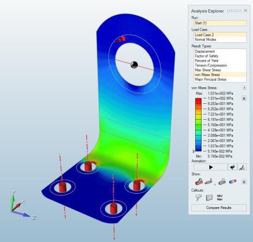

11 Analysis results Select Show Analysis Results Displacement Stress Normal Modes
12 Setting up Optimization


13 Design Space Creating Design Space: Right click the part Part 1 Slice 2 and click on Design Space Design Space


14 Shape Controls Creating Shape Controls: Select Add/Edit Shape Controls in Shape options in the Structure tab in the Ribbon Select the XZ plane and the YZ plane to disable it and to create a symmetry along X axis

15 Optimization Run Start Topography Optimization Run: Click on Run optimization Select Topography as a Run Type Leave the bead options as Default as shown in the figure Select Maximize frequencies and verify Load Case 2 is selected. Click on Run


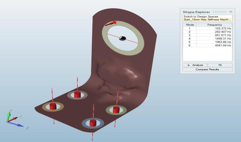
16 Load the Optimization Results Load the Optimization Results and click on Analyse Load the Optimization result Load the Analysis result of the optimized Shape

17 Analysis Results for Optimization-15mm The Displacement has reduced from The Frequency for first mode has to mm increased from to Hz

18 Start 2 nd Topography Optimization Run -10mm Change the name to Start_10mm Change the Minimum width to 10mm Leave all parameters same as for earlier optimization and click Run.
19 Load the 2 nd Optimization Results 10mm Load the Optimization Results The Displacement has The Frequency for first for 10mm and click on Analyze reduced further from mode has increased further to mm from to Hz

20 3 rd Optimization Results 5mm Similarly Run Optimization for Minimum width 5mm Load the Optimization Results The Displacement has The Frequency for first for 10mm and click on Analyze reduced further from mode has increased further to mm from to Hz Click on Compare Results


21 Comparison Use arrow at the top of Compare to adjust the available space Right click and enable Max von Mises stress
Step 1: Analyze a Baseline Model
 Step 1: Analyze a Baseline Model Let's start by opening the model and running a baseline analysis. Performing analysis on a model before setting up optimization helps ensure that any constraints and other
Finite Element Analysis with Inspire Finite Element Analysis By Rahul Ponginan Updated by Sanjay Nainani
 Finite Element Analysis with Inspire Finite Element Analysis By Rahul Ponginan Updated by Sanjay Nainani Finite Element Analysis was first developed over 60 years ago as a method to accurately predict
Step 1: Open the CAD model
 In this exercise you will learn how to: Ground a part Create rigid groups Add joints and an angle motor Add joints and an angle motor Run both transient and statics motion analyses Apply shape controls
CE Advanced Structural Analysis. Lab 4 SAP2000 Plane Elasticity
 Department of Civil & Geological Engineering COLLEGE OF ENGINEERING CE 463.3 Advanced Structural Analysis Lab 4 SAP2000 Plane Elasticity February 27 th, 2013 T.A: Ouafi Saha Professor: M. Boulfiza 1. Rectangular
Analysis Run Exercise
 Analysis Run Exercise In this exercise you will setup and run an analysis on the original design and the optimized design to compare the results. The exercise follows very closely the video in the See
3D Design with 123D Design
 3D Design with 123D Design Introduction: 3D Design involves thinking and creating in 3 dimensions. x, y and z axis Working with 123D Design 123D Design is a 3D design software package from Autodesk. A
RD-1070: Analysis of an Axi-symmetric Structure using RADIOSS
 RADIOSS, MotionSolve, and OptiStruct RD-1070: Analysis of an Axi-symmetric Structure using RADIOSS In this tutorial, you will learn the method of modeling an axi- symmetry problem in RADIOSS. The figure
TOPOLOGICAL, SIZE AND SHAPE OPTIMIZATION OF AN UNDERWING PYLON SPIGOT
 TOPOLOGICAL, SIZE AND SHAPE OPTIMIZATION OF AN UNDERWING PYLON SPIGOT Prepared by: M. Basaglia (Alenia Aermacchi), S. Boni Cerri (Alenia Aermacchi), G. Turinetti (Altair) Topological, Size and Shape Optimization
Spur Gears Static Stress Analysis with Linear Material Models
 Exercise A Spur Gears Static Stress Analysis with Linear Material Models Beam and Brick Elements Objective: Geometry: Determine the stress distribution in the spur gears when a moment of 93.75 in-lb is
Lesson 6: Assembly Structural Analysis
 Lesson 6: Assembly Structural Analysis In this lesson you will learn different approaches to analyze the assembly using assembly analysis connection properties between assembly components. In addition
Lesson: Lightweighting of Robot Gripper Arm
 Lesson: Lightweighting of Robot Gripper Arm This functionality is only available in Fusion 360 Ultimate. In this exercise we'll perform a Shape Optimization study to reduce the weight of a robot gripper
Finite Element Analysis Using Pro/Engineer
 Appendix A Finite Element Analysis Using Pro/Engineer A.1 INTRODUCTION Pro/ENGINEER is a three-dimensional product design tool that promotes practices in design while ensuring compliance with industry
ANSYS AIM Tutorial Structural Analysis of a Plate with Hole
 ANSYS AIM Tutorial Structural Analysis of a Plate with Hole Author(s): Sebastian Vecchi, ANSYS Created using ANSYS AIM 18.1 Problem Specification Pre-Analysis & Start Up Analytical vs. Numerical Approaches
Thermal Stress Analysis
 Thermal Stress Analysis Determine the temperature-induced stresses in a disk brake rotor. Lesson: Thermal Stress Analysis of a Disk Brake Rotor In this exercise we'll perform a Thermal Stress analysis
Types of Idealizations. Idealizations. Cylindrical Shaped Part. Cyclic Symmetry. 3D Shell Model. Axisymmetric
 Types of Idealizations Idealizations Selecting the model type 3D Solid Plane Stress Plane Strain 3D Shell Beam Cyclic Symmetry Cylindrical Shaped Part Interior Pressure Load 3D model can be used to model
DMU Engineering Analysis Review
 DMU Engineering Analysis Review Overview Conventions What's New? Getting Started Entering DMU Engineering Analysis Review Workbench Generating an Image Visualizing Extrema Generating a Basic Analysis Report
Similar Pulley Wheel Description J.E. Akin, Rice University
 Similar Pulley Wheel Description J.E. Akin, Rice University The SolidWorks simulation tutorial on the analysis of an assembly suggested noting another type of boundary condition that is not illustrated
Free-Shape Optimization of a 3-D Bracket using the Free-shape Method
 Free-Shape Optimization of a 3-D Bracket using the Free-shape Method In this exercise, shape optimization on a solid bracket model will be performed using the Free- Shape optimization method. The objective
3ds Max Cottage Step 1. Always start out by setting up units: We re going with this setup as we will round everything off to one inch.
 3ds Max Cottage Step 1 Always start out by setting up units: We re going with this setup as we will round everything off to one inch. File/Import the CAD drawing Be sure Files of Type is set to all formats
Exercise 1. 3-Point Bending Using the Static Structural Module of. Ansys Workbench 14.0
 Exercise 1 3-Point Bending Using the Static Structural Module of Contents Ansys Workbench 14.0 Learn how to...1 Given...2 Questions...2 Taking advantage of symmetries...2 A. Getting started...3 A.1 Choose
= 21
 CE 331, Spring 2011 Guide for Using RISA3D to Model a Balsa Structure 1 / 9 0. Example Bridge. An example structure is shown below. Typical results for the RISA model of this structure are shown throughout
Exercise 1. 3-Point Bending Using the GUI and the Bottom-up-Method
 Exercise 1 3-Point Bending Using the GUI and the Bottom-up-Method Contents Learn how to... 1 Given... 2 Questions... 2 Taking advantage of symmetries... 2 A. Preprocessor (Setting up the Model)... 3 A.1
ENGINEERING TRIPOS PART IIA FINITE ELEMENT METHOD
 ENGINEERING TRIPOS PART IIA LOCATION: DPO EXPERIMENT 3D7 FINITE ELEMENT METHOD Those who have performed the 3C7 experiment should bring the write-up along to this laboratory Objectives Show that the accuracy
Introduction to Nastran SOL 200 Design Sensitivity and Optimization
 Introduction to Nastran SOL 200 Design Sensitivity and Optimization PRESENTED BY: CHRISTIAN APARICIO The Nastran Engineering SOL 200 questions? Lab Email me: christian@ the-engineering-lab.com Motivation
Lesson: Static Stress Analysis of a Connecting Rod Assembly
 Lesson: Static Stress Analysis of a Connecting Rod Assembly In this tutorial we determine the effects of a 2,000 pound tensile load acting on a connecting rod assembly (consisting of the rod and two pins).
Lab#5 Combined analysis types in ANSYS By C. Daley
 Engineering 5003 - Ship Structures I Lab#5 Combined analysis types in ANSYS By C. Daley Overview In this lab we will model a simple pinned column using shell elements. Once again, we will use SpaceClaim
In-plane principal stress output in DIANA
 analys: linear static. class: large. constr: suppor. elemen: hx24l solid tp18l. load: edge elemen force node. materi: elasti isotro. option: direct. result: cauchy displa princi stress total. In-plane
Topology and Shape optimization within the ANSA-TOSCA Environment
 Topology and Shape optimization within the ANSA-TOSCA Environment Introduction Nowadays, manufacturers need to design and produce, reliable but still light weighting and elegant components, at minimum
2: Static analysis of a plate
 2: Static analysis of a plate Topics covered Project description Using SolidWorks Simulation interface Linear static analysis with solid elements Finding reaction forces Controlling discretization errors
Sliding Split Tube Telescope
 LESSON 15 Sliding Split Tube Telescope Objectives: Shell-to-shell contact -accounting for shell thickness. Creating boundary conditions and loads by way of rigid surfaces. Simulate large displacements,
Abaqus/CAE Axisymmetric Tutorial (Version 2016)
") Abaqus/CAE Axisymmetric Tutorial (Version 2016) Problem Description A round bar with tapered diameter has a total load of 1000 N applied to its top face. The bottom of the bar is completely fixed. Determine
Abaqus/CAE Axisymmetric Tutorial (Version 2016) Problem Description A round bar with tapered diameter has a total load of 1000 N applied to its top face. The bottom of the bar is completely fixed. Determine
A05 Steel Catenary Riser Systems
 A05 Steel Catenary Riser Systems Introduction This example contains three examples of steel catenary risers (SCRs). These are: Catenary with Spar Catenary with SemiSub Lazy Wave with FPSO The example also
Finite Element Analysis Using Creo Simulate 4.0
 Introduction to Finite Element Analysis Using Creo Simulate 4.0 Randy H. Shih SDC PUBLICATIONS Better Textbooks. Lower Prices. www.sdcpublications.com Powered by TCPDF (www.tcpdf.org) Visit the following
GTS NX INTERFACES AUTOCAD MIDAS GEN FOR TUNNEL SOIL PILE INTERACTION ANALYSIS
 INTERFACES AUTOCAD MIDAS GEN FOR TUNNEL SOIL PILE INTERACTION ANALYSIS Angel F. Martinez Civil Engineer MIDASOFT Integrated Solver Optimized for the next generation 64-bit platform Finite Element Solutions
ME Optimization of a Frame
 ME 475 - Optimization of a Frame Analysis Problem Statement: The following problem will be analyzed using Abaqus. 4 7 7 5,000 N 5,000 N 0,000 N 6 6 4 3 5 5 4 4 3 3 Figure. Full frame geometry and loading
CATIA V5 Parametric Surface Modeling
 CATIA V5 Parametric Surface Modeling Version 5 Release 16 A- 1 Toolbars in A B A. Wireframe: Create 3D curves / lines/ points/ plane B. Surfaces: Create surfaces C. Operations: Join surfaces, Split & Trim
Training Guide TopSolid Fea
 Training Guide i 2012, Missler Software. 7, Rue du Bois Sauvage F-91055 Evry, FRANCE Web: http://www.topsolid.com E-mail: info@topsolid.com All rights reserved. This information is subject to change without
Topology Optimization of an Engine Bracket Under Harmonic Loads
 Topology Optimization of an Engine Bracket Under Harmonic Loads R. Helfrich 1, A. Schünemann 1 1: INTES GmbH, Schulze-Delitzsch-Str. 16, 70565 Stuttgart, Germany, www.intes.de, info@intes.de Abstract:
Creating a T-Spline using a Reference Image
 1 / 17 Goals Learn how to create a T-Spline using a Reference Image. 1. Insert an image into the workspace using Attach Canvas. 2. Use Calibrate to set the proper scale for the reference image. 3. Invoke
New Capabilities in Project Hydra for Autodesk Simulation Mechanical
 New Capabilities in Project Hydra for Autodesk Simulation Mechanical Sualp Ozel, PE. Autodesk SM2447-L In this hands-on lab, we will go through several exercises and cover several new capabilities included
The Essence of Result Post- Processing
 APPENDIX E The Essence of Result Post- Processing Objectives: Manually create the geometry for the tension coupon using the given dimensions then apply finite elements. Manually define material and element
Workshop MSC Nastran Topology Optimization Manufacturing Constraints
 Workshop MSC Nastran Topology Optimization Manufacturing Constraints AN MSC NASTRAN SOL 200 TUTORIAL The Nastran Engineering SOL 200 questions? Lab Email me: christian@ the engineering lab.com Goal: Use
CE366/ME380 Finite Elements in Applied Mechanics I Fall 2007
 CE366/ME380 Finite Elements in Applied Mechanics I Fall 2007 FE Project 1: 2D Plane Stress Analysis of acantilever Beam (Due date =TBD) Figure 1 shows a cantilever beam that is subjected to a concentrated
Section 7.2 Volume: The Disk Method
 Section 7. Volume: The Disk Method White Board Challenge Find the volume of the following cylinder: No Calculator 6 ft 1 ft V 3 1 108 339.9 ft 3 White Board Challenge Calculate the volume V of the solid
300 N All lengths in meters. Step load applied at time 0.0.
 Problem description In this problem, we subject the beam structure of problem 1 to an impact load as shown. 300 N 0.02 0.02 1 All lengths in meters. Step load applied at time 0.0. E = 2.07 10 11 N/m 2
Learning Module 8 Shape Optimization
 Learning Module 8 Shape Optimization What is a Learning Module? Title Page Guide A Learning Module (LM) is a structured, concise, and self-sufficient learning resource. An LM provides the learner with
Rectangular Coordinates in Space
 Rectangular Coordinates in Space Philippe B. Laval KSU Today Philippe B. Laval (KSU) Rectangular Coordinates in Space Today 1 / 11 Introduction We quickly review one and two-dimensional spaces and then
SOEM 024: Computer Aided Design. E. Rozos
 SOEM 024: Computer Aided Design E. Rozos Lesson structure Construct 3D objects with revolving WCS UCS Master plotting Realism Geometrical analysis Stress analysis Kinematics dynamic simulation Revolve,
SDC. Engineering Analysis with COSMOSWorks. Paul M. Kurowski Ph.D., P.Eng. SolidWorks 2003 / COSMOSWorks 2003
 Engineering Analysis with COSMOSWorks SolidWorks 2003 / COSMOSWorks 2003 Paul M. Kurowski Ph.D., P.Eng. SDC PUBLICATIONS Design Generator, Inc. Schroff Development Corporation www.schroff.com www.schroff-europe.com
CATIA V5 FEA Tutorials Release 14
 CATIA V5 FEA Tutorials Release 14 Nader G. Zamani University of Windsor SDC PUBLICATIONS Schroff Development Corporation www.schroff.com www.schroff-europe.com CATIA V5 FEA Tutorials 2-1 Chapter 2 Analysis
Getting Started. These tasks should take about 20 minutes to complete. Getting Started
 Getting Started Getting Started This tutorial will guide you step-by-step through your first ELFINI and Generative Part Structural Analysis session, allowing you to get acquainted with the product. You
THREE-DIMENSIONAL PROBLEM OF THE THEORY OF ELASTICITY STRESS IN A THICK-WALLED PRESSURE VESSEL
 THREE-DIMENSIONAL PROBLEM OF THE THEORY OF ELASTICITY STRESS IN A THICK-WALLED PRESSURE VESSEL 1. INTRODUCTION Three-dimensional problem of the theory of elasticity includes an elastic body with defined
Embedded Reinforcements
 Embedded Reinforcements Gerd-Jan Schreppers, January 2015 Abstract: This paper explains the concept and application of embedded reinforcements in DIANA. Basic assumptions and definitions, the pre-processing
Post-Processing Static Results of a Space Satellite
 LESSON 7 Post-Processing Static Results of a Space Satellite 3.84+05 3.58+05 3.33+05 3.07+05 2.82+05 3.84+05 2.56+05 2.30+05 2.05+05 1.79+05 1.54+05 1.28+05 1.02+05 7.68+04 0. 5.12+04 Z Y X Objectives:
Introduction To Finite Element Analysis
 Creating a Part In this part of the tutorial we will introduce you to some basic modelling concepts. If you are already familiar with modelling in Pro Engineer you will find this section very easy. Before
Free-shape Optimization of a Bracket
 Free-shape Optimization of a Bracket In this exercise, shape optimization on a solid model will be performed using the free-shape optimization method along with manufacturing constraints, such as symmetry
Workshop 3.1 2D Gear and Rack Analysis
 Workshop 3.1 2D Gear and Rack Analysis 16.0 Release Introduction to ANSYS Mechanical 1 2015 ANSYS, Inc. February 27, 2015 Assumptions Workshop 3.1 consists of a 2 part assembly representing spur and rack
Deep Beam With Web Opening
 Deep Beam With Web Opening Name: Path: Keywords: DeepBeamWithWebOpening/deepbeam /Examples//DeepBeamWithWebOpening/deepbeam analys: linear static. constr: suppor. elemen: cq16m ct12m pstres. load: force
TRINITAS. a Finite Element stand-alone tool for Conceptual design, Optimization and General finite element analysis. Introductional Manual
 TRINITAS a Finite Element stand-alone tool for Conceptual design, Optimization and General finite element analysis Introductional Manual Bo Torstenfelt Contents 1 Introduction 1 2 Starting the Program
ABOUT OPTIMIZATION DESIGN STUDY ON SOLIDWORKS
 ABOUT OPTIMIZATION DESIGN STUDY ON SOLIDWORKS prof.phd.eng. Cătălin IANCU Engineering and Sustainable Development Faculty, C-tin Brâncuşi Univ. of Tg-Jiu, ciancu@utgjiu.ro Abstract: In this paper are presented
CHAPTER 8 FINITE ELEMENT ANALYSIS
 If you have any questions about this tutorial, feel free to contact Wenjin Tao (w.tao@mst.edu). CHAPTER 8 FINITE ELEMENT ANALYSIS Finite Element Analysis (FEA) is a practical application of the Finite
ME Week 12 Piston Mechanical Event Simulation
 Introduction to Mechanical Event Simulation The purpose of this introduction to Mechanical Event Simulation (MES) project is to explorer the dynamic simulation environment of Autodesk Simulation. This
Principal Roll Structure Design Using Non-Linear Implicit Optimisation in Radioss
 Principal Roll Structure Design Using Non-Linear Implicit Optimisation in Radioss David Mylett, Dr. Simon Gardner Force India Formula One Team Ltd. Dadford Road, Silverstone, Northamptonshire, NN12 8TJ,
Static Stress Analysis
 Static Stress Analysis Determine stresses and displacements in a connecting rod assembly. Lesson: Static Stress Analysis of a Connecting Rod Assembly In this tutorial we determine the effects of a 2,000-pound
Autodesk Fusion 360 Training: The Future of Making Things Attendee Guide
 Autodesk Fusion 360 Training: The Future of Making Things Attendee Guide Abstract After completing this workshop, you will have a basic understanding of editing 3D models using Autodesk Fusion 360 TM to
Exercise 1: Axle Structural Static Analysis
 Exercise 1: Axle Structural Static Analysis The purpose of this exercise is to cover the basic functionality of the Mechanical Toolbar (MTB) in the context of performing an actual analysis. Details of
Aufgabe 1: Dreipunktbiegung mit ANSYS Workbench
 Aufgabe 1: Dreipunktbiegung mit ANSYS Workbench Contents Beam under 3-Pt Bending [Balken unter 3-Pkt-Biegung]... 2 Taking advantage of symmetries... 3 Starting and Configuring ANSYS Workbench... 4 A. Pre-Processing:
= Set the units Click on the units icon, and change the default units to lbs and inches for:
 CE 331, Fall 2012 Guide for Using RISA3D to Model a Balsa Structure 1 / 9 Example Bridge. An example structure is shown below. Typical results for the RISA model of this structure are shown throughout
Chapter 2. Walkthrough example
 Figure 2.1. Working environment of the OmniView postprocessor for OmniTrak Chapter 2. Walkthrough example 2.1. Geometry and mesh definition This chapter reviews an application example to give a quick overview
Coustyx Tutorial Indirect Model
 Coustyx Tutorial Indirect Model 1 Introduction This tutorial is created to outline the steps required to compute radiated noise from a gearbox housing using Coustyx software. Detailed steps are given on
Optimizing the Utility Scale Solar Megahelion Drive End-Cap (Imperial Units)
") Autodesk Inventor Tutorial Exercise Optimizing the Utility Scale Solar Megahelion Drive End-Cap www.autodesk.com/sustainabilityworkshop Contents OPTIMIZING THE USS SOLAR TRACKING END CAP... 3 OBJECTIVE...
Autodesk Inventor Tutorial Exercise Optimizing the Utility Scale Solar Megahelion Drive End-Cap www.autodesk.com/sustainabilityworkshop Contents OPTIMIZING THE USS SOLAR TRACKING END CAP... 3 OBJECTIVE...
3DEXPERIENCE 2017x FINITE ELEMENT ESSENTIALS IN SDC USING SIMULIA/CATIA APPLICATIONS. Nader G. Zamani
 Nader G. Zamani FINITE ELEMENT ESSENTIALS IN 3DEXPERIENCE 2017x USING SIMULIA/CATIA APPLICATIONS SDC PUBLICATIONS Better Textbooks. Lower Prices. www.sdcpublications.com Powered by TCPDF (www.tcpdf.org)
Unit #13 : Integration to Find Areas and Volumes, Volumes of Revolution
 Unit #13 : Integration to Find Areas and Volumes, Volumes of Revolution Goals: Beabletoapplyaslicingapproachtoconstructintegralsforareasandvolumes. Be able to visualize surfaces generated by rotating functions
Leapfrog Geothermal 3.5
 Leapfrog Geothermal 3.5 Technical release notes This document outlines the major features and improvements in Leapfrog Geothermal 3.5. More information about Leapfrog Geo can be found online at www.leapfrog3d.com
Appendix B: Creating and Analyzing a Simple Model in Abaqus/CAE
 Getting Started with Abaqus: Interactive Edition Appendix B: Creating and Analyzing a Simple Model in Abaqus/CAE The following section is a basic tutorial for the experienced Abaqus user. It leads you
Structural re-design of engine components
 Structural re-design of engine components Product design cycle Design Development Testing Structural optimization Product knowledge Design freedom 2/18 Structural re-design of engine components Product
A pipe bend is subjected to a concentrated force as shown: y All dimensions in inches. Material is stainless steel.
 Problem description A pipe bend is subjected to a concentrated force as shown: y 15 12 P 9 Displacement gauge Cross-section: 0.432 18 x 6.625 All dimensions in inches. Material is stainless steel. E =
ANSYS Workbench Guide
 ANSYS Workbench Guide Introduction This document serves as a step-by-step guide for conducting a Finite Element Analysis (FEA) using ANSYS Workbench. It will cover the use of the simulation package through
Introduction: RS 3 Tutorial 1 Quick Start
 Introduction: RS 3 Tutorial 1 Quick Start Welcome to RS 3. This tutorial introduces some basic features of RS 3. The model analyzes the effect of tank loading on an existing sloped underground tunnel.
COPYRIGHT DASSAULT SYSTEMES Version 5 Release 19 January 2009 EDU-CAT-EN-ASL-FS-V5R19
 CATIA Training CATIA Aerospace Sheet Metal Design Detailed Steps COPYRIGHT DASSAULT SYSTEMES Version 5 Release 19 January 2009 EDU-CAT-EN-ASL-FS-V5R19 Table of Contents Additional Exercise: Aerostructure...3
Elastic Analysis of a Deep Beam with Web Opening
 Elastic Analysis of a Deep Beam with Web Opening Outline 1 Description 2 Finite Element Model 2.1 Units 2.2 Geometry definition 2.3 Properties 2.4 Boundary conditions 2.4.1 Constraints 2.4.2 Vertical load
Creating and Analyzing a Simple Model in Abaqus/CAE
 Appendix B: Creating and Analyzing a Simple Model in Abaqus/CAE The following section is a basic tutorial for the experienced Abaqus user. It leads you through the Abaqus/CAE modeling process by visiting
CATIA Electrical Space Reservation TABLE OF CONTENTS
 TABLE OF CONTENTS Introduction...1 Manual Format...2 Electrical Reservations...3 Equipment Reservations...5 Pathway Reservations...31 Advanced Reservations...49 Reservation Analysis...67 Clash...69 Sectioning...73
Example 24 Spring-back
 Example 24 Spring-back Summary The spring-back simulation of sheet metal bent into a hat-shape is studied. The problem is one of the famous tests from the Numisheet 93. As spring-back is generally a quasi-static
Standard Operating Procedure of Triboindenter (Hysitron TI 950)
") Standard Operating Procedure of Triboindenter (Hysitron TI 950) I Sample Loading and Preparation DO NOT TOUCH the bottom of transducer and optical microscope. Always place the tall samples on the most
Standard Operating Procedure of Triboindenter (Hysitron TI 950) I Sample Loading and Preparation DO NOT TOUCH the bottom of transducer and optical microscope. Always place the tall samples on the most
Workshop 15. Single Pass Rolling of a Thick Plate
 Introduction Workshop 15 Single Pass Rolling of a Thick Plate Rolling is a basic manufacturing technique used to transform preformed shapes into a form suitable for further processing. The rolling process
Slope Stability of Open Pit Mine in 2D & 3D
 Slope Stability of Open Pit Mine in D & D MIDASoft Inc. Angel Francisco Martinez Civil Engineer Email : a.martinez@midasit.com Integrated Solver Optimized for the next generation64-bit platform Finite
Exercise 1: 3-Pt Bending using ANSYS Workbench
 Exercise 1: 3-Pt Bending using ANSYS Workbench Contents Starting and Configuring ANSYS Workbench... 2 1. Starting Windows on the MAC... 2 2. Login into Windows... 2 3. Start ANSYS Workbench... 2 4. Configuring
Create Complex Surfaces
 Create Complex Surfaces In this lesson, you will be introduced to the functionalities available in the Generative Surface Design workbench. Lesson content: Case Study: Surface Design Design Intent Stages
Lesson 4: Surface Re-limitation and Connection
 Lesson 4: Surface Re-limitation and Connection In this lesson you will learn how to limit the surfaces and form connection between the surfaces. Lesson contents: Case Study: Surface Re-limitation and Connection
Stresses in an Elliptical Beam
 Problem: An offset tensile link is shaped to clear an obstruction with a geometry as shown in the figure. The cross section at the critical location is elliptical, with a major axis of 4 in and a minor
3 AXIS STANDARD CAD. BobCAD-CAM Version 28 Training Workbook 3 Axis Standard CAD
 3 AXIS STANDARD CAD This tutorial explains how to create the CAD model for the Mill 3 Axis Standard demonstration file. The design process includes using the Shape Library and other wireframe functions
16 SW Simulation design resources
 16 SW Simulation design resources 16.1 Introduction This is simply a restatement of the SW Simulation online design scenarios tutorial with a little more visual detail supplied on the various menu picks
TUTORIAL 7: Stress Concentrations and Elastic-Plastic (Yielding) Material Behavior Initial Project Space Setup Static Structural ANSYS ZX Plane
 Material Behavior Initial Project Space Setup Static Structural ANSYS ZX Plane") TUTORIAL 7: Stress Concentrations and Elastic-Plastic (Yielding) Material Behavior In this tutorial you will learn how to recognize and deal with a common modeling issues involving stress concentrations
TUTORIAL 7: Stress Concentrations and Elastic-Plastic (Yielding) Material Behavior In this tutorial you will learn how to recognize and deal with a common modeling issues involving stress concentrations
Solved with COMSOL Multiphysics 4.2
 Backstep Introduction This tutorial model solves the incompressible Navier-Stokes equations in a backstep geometry. A characteristic feature of fluid flow in geometries of this kind is the recirculation
QUIZ 4 (CHAPTER 17) SOLUTIONS MATH 252 FALL 2008 KUNIYUKI SCORED OUT OF 125 POINTS MULTIPLIED BY % POSSIBLE
 SOLUTIONS MATH 252 FALL 2008 KUNIYUKI SCORED OUT OF 125 POINTS MULTIPLIED BY % POSSIBLE") QUIZ 4 (CHAPTER 17) SOLUTIONS MATH 5 FALL 8 KUNIYUKI SCORED OUT OF 15 POINTS MULTIPLIED BY.84 15% POSSIBLE 1) Reverse the order of integration, and evaluate the resulting double integral: 16 y dx dy. Give
QUIZ 4 (CHAPTER 17) SOLUTIONS MATH 5 FALL 8 KUNIYUKI SCORED OUT OF 15 POINTS MULTIPLIED BY.84 15% POSSIBLE 1) Reverse the order of integration, and evaluate the resulting double integral: 16 y dx dy. Give
Stiffened Plate With Pressure Loading
 Supplementary Exercise - 3 Stiffened Plate With Pressure Loading Objective: geometry and 1/4 symmetry finite element model. beam elements using shell element edges. MSC.Patran 301 Exercise Workbook Supp3-1
Abaqus/CAE (ver. 6.11) Nonlinear Buckling Tutorial
 Nonlinear Buckling Tutorial") Abaqus/CAE (ver. 6.11) Nonlinear Buckling Tutorial Problem Description This is the NAFEMS 1 proposed benchmark (Lee s frame buckling) problem. The applied load is based on the normalized (EI/L 2 ) value
Abaqus/CAE (ver. 6.11) Nonlinear Buckling Tutorial Problem Description This is the NAFEMS 1 proposed benchmark (Lee s frame buckling) problem. The applied load is based on the normalized (EI/L 2 ) value
FreeStyle Shaper & Optimizer
 FreeStyle Shaper & Optimizer Preface What's New Getting Started Basic Tasks Advanced Tasks Workbench Description Customizing Glossary Index Dassault Systèmes 1994-99. All rights reserved. Preface CATIA
Inventor 201. Work Planes, Features & Constraints: Advanced part features and constraints
 Work Planes, Features & Constraints: 1. Select the Work Plane feature tool, move the cursor to the rim of the base so that inside and outside edges are highlighted and click once on the bottom rim of the