Training Guide TopSolid Fea
|
|
|
- Junior Glenn
- 6 years ago
- Views:
Transcription


1 Training Guide i
2 2012, Missler Software. 7, Rue du Bois Sauvage F Evry, FRANCE Web: All rights reserved. This information is subject to change without warning. No material may be reproduced or transmitted, regardless of the manner, electronic or mechanical means used or purpose, without formal written consent from Missler Software. TopSolid is a registered trademark of Missler Software. TopSolid is a product name of Missler Software. The information and the software contained within this document are subject to change without prior warning and should not be construed as a commitment by Missler Software. The software covered by this document is supplied under license, and may only be used and duplicated in compliance with the terms of this license. Version 7.6 Rev.01 ii Missler Software
3 Contents Quick Analysis... 1 Creating the Analysis Preparation Document... 1 Starting the Analysis Solving... 6 Displaying the Stresses... 6 Amplifying the Result... 7 Generating the Calculation Report... 8 Customizing the Support Adding a Logo Modifying the Font and the Text Changing the Font for the Whole Document Changing the Header Advanced Analysis Creating a Simplified Version Loads and Blockings Manual Mesh Simplifying the Model Local Meshes Modal Analysis Free Exercise: Modal Analysis Buckling Calculation Notes Individual Course Evaluation Form Missler Software iii
4

5 Quick Analysis This first exercise teaches you how to perform a static analysis using the wizard. Quick Analysis Import the package named TopSolid.Fea.Us.TopPkg. Open the 1 - Bracket - Express folder, and then the Bracket part document. Creating the Analysis Preparation Document This type of document allows you to define calculation assumptions and, if necessary, to modify the part needed for the calculation without modifying the model. Bring up the contextual menu on the Bracket part document s upper tab, select Analysis Preparation, and then choose Blank Template. Fill in the Include Part or Assembly dialog box as follows: - Source Document: Bracket. - Representation: select Detailed Representation from the drop-down list. In the New Analysis dialog box, fill in the following fields: - Analysis to Create: select Linear Static Analysis from the drop-down list. - Uncheck Fast Method. - Check Wizard. Notes: There are three types of analysis: - Linear static; - Modal; - Linear buckling. Only the static analysis is discussed in detail throughout this guide, because of the limits set by the Express module. For your information, the Express module is limited to nodes. The fast method can only be used together with the Fea Advanced and Fea Assembly modules. This method means using the mesher of the INRIA (French National Institute for Research in Computer Science and Control) which provides results more quickly. Missler Software 1
6 Quick Analysis The holders of the Fea Express unique module (included in TopSolid Pro for example) can only use the face by face mesher of the CETIM (technical center for mechanical engineers). The Fast Method option is then grayedout. In the Analysis tab, select the Wizard command. The following window opens automatically. The analysis validation wizard summarizes the state of the different stages of the analysis: - Material (the green flag indicates that the material is well-defined and that three steps still need to be validated) ; - Meshing; - Loads; - Limit conditions. In the Steps description column, click on Some geometries are still not meshed and, in the Possible actions column, double-click on Mesh study geometries. 2 Missler Software


7 Quick Analysis Choose the Face by face meshing method from the drop-down list. Keep the default values. Note: The default values are the best compromise between fast calculation time and more accurate results that we will obtain later when launching the solving process. The meshing progress bar appears. In the system bar at the very top of the screen, the meshing stage is then automatically activated. - Modeling Stage: This stage involves the operation to include the part or assembly document to analyze. - Simplification Stage: This stage includes the different operations for simplifying the geometry. - Definition Stage: This stage includes the compulsory analysis steps of a part. You should then end up with the following result: Note that a mesh is correct when triangles are equilateral. TopSolid automatically creates a Meshes folder in your document s Entities tree and also a Mesh operation in your document s Operations tree. There are three basic ways of editing this mesh: In the Meshes folder, bring up the contextual menu on Mesh, and then Edit. In the Operations tree, bring up the contextual menu on the meshing operation, and then Edit. In the graphical area, bring up the contextual menu on, and then Edit. In the Analysis tab, select the Wizard command again. Missler Software 3

8 Quick Analysis There is now a green flag in front of Geometries are all meshed. Click the No loads defined stage, and then double-click on Uniform surface load can be added. Select the upper face of the part on which to apply a surface force and set the value to 500N. Reverse the direction of the arrow, and then validate. A symbol for the surface load appears on the upper face. 4 Missler Software


9 The wizard window opens, indicating that the Load(s) defined stage is validated (green flag). Quick Analysis Select the last stage to be validated Insufficient boundary conditions, and then double-click on Clamp can be added. Select the end face, and then validate. A symbol for the clamp appears on the face. At this point, all the flags are green. Save your document. Missler Software 5
 in the Project tree.")

10 Quick Analysis Starting the Analysis Solving In the Analysis tab, select the Solver command. The solving progress bar appears. The solution of the analysis automatically creates a new analysis result document called Bracket (Linear Static Analysis 1) in the Project tree. The first result Norm of Displacements is shown in the graphical area. Displaying the Stresses In the Results tab, select Stresses Result, choose Von Mises from the drop-down list, and then validate. Repeat the operation by selecting this time the Tresca stresses. Each selected result is stored and will be used in the report. 6 Missler Software


11 Quick Analysis TopSolid automatically creates in the document s Entities tree a Results folder containing the following items: - Tresca Stresses; - Von Mises Stresses; - Norm of Displacements. You can switch between results by bringing up the contextual menu on the desired result and then selecting Set as Current. The bold title corresponds to the current result that is shown in the graphical area. Amplifying the Result In order to visually ascertain the result, the distortion can be exaggerated by modifying the scale factor. Set the Max Scale Factor to 2 and enter 0,5 in the Scale Factor field or use the cursor to reach this value. Using the Measure analysis tool, you can obtain all information from the selected node or item. Keep the Node default selection mode. Select a node (the junction point of the mesh for example). All the relevant information appears in the Result dialog section (displacements and stresses). Note that you can choose the Element selection mode if necessary. Missler Software 7

12 Quick Analysis Generating the Calculation Report In the Results tab, select Report Generation. Click the Browse button and select Report Static Analysis from the Standard Templates. Keep the Include in Project default option. This option allows you to save the report in the current project. Choose the Adobe Pdf export format from the drop-down list. Rename the report or keep the default name. The message Compiling report will appear very quickly on the screen, indicating us that the report is being generated. Click the project name and validate. 8 Missler Software
13 The report in PDF format is generated in the Project tree and shown on the screen. Quick Analysis Read the result, and then close the PDF document. Using the Alt + Tab key combination, bring the Report Preview document to front and close it. Missler Software 9


14 Customizing the Support Customizing the Support This exercise teaches you how to customize the logo and modify the text. Bring up the contextual menu on the project name and create a new document. In the Special tab, select Report Definition. Choose the Report Static Analysis template, and then validate. Rename the document to My Report. A window opens prompting you to choose the interface type. Select the interface you want. The report builder shows all the data of the standard report. Adding a Logo Double-click in the \LogoMissler.jpg field. Open the file corresponding to your logo. 10 Missler Software


15 In the Properties column, select Stretch and set the value to True. Customizing the Support The logo should fully appear in the box. Move the box to the center just by dragging it. Modifying the Font and the Text Modify the font of the text Static analysis report. To do this, click on the text, select the font Calibri and set the size to 20 points. Missler Software 11

16 Customizing the Support Changing the Font for the Whole Document Use the Ctrl + A key combination to select all your text. Choose the Calibri font. Press the Esc key to release the selection. Changing the Header Double-click the text to be modified. Enter your desired text, and then click OK. Close the document. Save the report. Drag the report template into the Defaults subfolder of the Templates folder in the Project tree. Generate a new calculation report using the template created before. 12 Missler Software

17 Advanced Analysis Advanced Analysis In the Project tree, open the 2 - Lever Simplification folder, and then the Lever part document. Creating a Simplified Version In the Operations tree, move the modeling cursor above the Trim by Profile 2 operation. Bring up the contextual menu on the part and select Others > Duplicate into Representation. In the current dialog box, check New, rename it to Calculation, and then validate. Note that TopSolid automatically creates the Calculation representation in the Representations folder. Move up the modeling cursor and save the document. Bring up the contextual menu on the Lever document s upper tab, select Analysis Preparation and choose Blank Template. - Source Document: Lever. - Representation: select Calculation from the drop-down list. Validate. In the New Analysis dialog box, fill in the following parameters: - Analysis to Create: choose Linear Static Analysis from the drop-down list. - Check Fast Method. - Uncheck Wizard. Missler Software 13
18 Advanced Analysis Loads and Blockings In the Analysis tab, select the Clamp command. Select the cylindrical face shown below, and then validate. Note: In the Advanced Options dialog section, you can impose a direction if necessary. Otherwise, the clamp is performed in all directions. In the Analysis tab, select the Surface Load command. Select the two cylindrical surfaces of the vertical axis. - Type: check Load. - Imposed: check the Z Direction and reverse the arrow direction. - Value: enter 2000N. Validate. Repeat the operation on the second vertical axis by checking the X direction. You should then end up with the following result. You can apply a transparency to the part to obtain the following rendering. Manual Mesh In the Mesh tab, select the Mesh Shape command. Select the Automatic meshing method and keep the default target size. 14 Missler Software

19 Advanced Analysis In the Analysis tab, select the Solver command. Simplifying the Model Keep in mind the previous calculation time. Now we will simplify the part by symmetry to accelerate the process. Close all documents except the Lever part document. Create a new analysis preparation document and rename it to Lever-Symmetry. In the Shape tab, select Make Locally Modifiable. Select the part and validate. This command allows you to perform operations on the part without modifying the original model. Create a trim by plane using the XZ plane. Block and add the loads using 1000N per face. Add an imposed displacement and fill in the fields as follows: - Geometries: select the symmetry face. - Direction: select the symmetry face. - Value: enter 0. Validate. A symbol for the imposed displacement is shown on the face. Missler Software 15


20 Advanced Analysis Mesh the shape in Automatic mode and keep the default target size value. In the Analysis tab, select the Solver command. The calculation time is twice faster than before. Save and close all documents. Local Meshes The mesh must be refined in the following cases: - near the holes; - near the cracks; 16 Missler Software


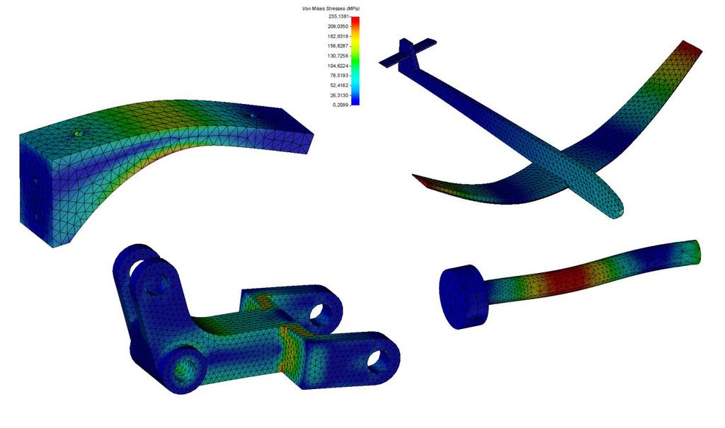
21 - in reentering corners; Advanced Analysis - where there is a sudden cross-section change; - in load transfer area: welding; - where there are concentrated loads. In short, you have to refine the mesh in areas with singularities or large amounts of stress. Open the 3 - Crank - Local Meshes folder, and then the Crank part document. Create a new analysis preparation document and select Blank Template. Validate the inclusion. Select Linear Static Analysis and check Wizard. Mesh the shape and keep the following default values: - Select the face by face meshing method from the drop-down list. - Set the target size to 5.1 mm. - Set the minimum size to 3.6 mm. - Set the size tolerance to 0.36 mm. Missler Software 17

22 Advanced Analysis In the Mesh tab, select Local Size. Select the hole edges and the crank pin edges as shown below, and enter 1 mm in the Size of Elements field. The mesh is then recalculated as shown below. Note: TopSolid automatically creates a Local Meshes folder in your document s Entities tree. If you want to modify the local meshes, you have to go through this folder. You can also turn off the meshing auto refresh in case the shape or the mesh settings are modified by right-clicking on a meshing in the Entities tree and then unchecking Auto Refresh. If auto refresh is off, the meshing is recalculated when a solving is launched. Add a surface load of 750N at the end of the crank pin, and then add a clamp into the hole. 18 Missler Software

23 Advanced Analysis In the Analysis tab, select the Solver command. Select the Stresses Result command and choose Von Mises from the drop-down list. Save and close the documents. Modal Analysis Note: Natural frequency is the frequency at which a system naturally vibrates once it has been set into motion. In other words, natural frequency is the number of times a system will oscillate (move back and forth) between its original position and its displaced position, if there is no outside interference. Open the 4 - Plane - Natural Frequencies folder, and then the Wing part document. Create a new analysis preparation document and select Blank Template. Validate the inclusion. Select Modal Analysis from the drop-down list and check Wizard. Mesh the shape and keep the following default values: - Select the Automatic meshing method from the drop-down list. - Set the target size to 2.3 mm. Add a clamp at the end of the shape. Missler Software 19


24 Advanced Analysis In the Analysis tab, select the Solver command. Open the Results folder in the Entities tree. The first natural frequency is calculated. Select the Scale Factor command to amplify the results. Use the Natural Frequencies command, and then select the first five natural frequencies. The Results folder now contains the five natural frequencies. The fifth natural frequency is the current one. To see the results of a frequency, bring up the contextual menu on a frequency and select Set as Current. Open the analysis preparation document and change the mesh to 1. Open the analysis solving document. As you can see, the calculation update is automatically restarted. The calculation is much longer but also more accurate. Free Exercise: Modal Analysis Open the Plane part document. Repeat the same steps as for the wing. Note that the clamp will be applied on the back face. 20 Missler Software


25 Buckling Calculation Advanced Analysis Buckling is an instability phenomenon that is characterized by the occurrence of transverse deformations in members under compression forces. Open the 5 - Cylinder Rod - Buckling folder, and then the Cylinder Rod part document. Create a new analysis preparation document and select Blank Template. Validate the inclusion. Select Linear Static Analysis and check Wizard. Mesh the shape and fill in the following values: - Select the face by face meshing method from the drop-down list. - Set the target size to 10mm. - Set the minimum size to 5mm. - Set the size tolerance to 1mm. In the Mesh tab, select Local Size. Refine the junction edge of the small cylinder with the large cylinder and enter 2.5mm in the Size of Elements field. Add a surface load of 5000N at the end of the rod, and then add a clamp on the back cylindrical face as shown below. Select New Analysis again. Choose Linear Buckling Analysis from the drop-down list and use the previous static analysis. Select the Solver command. Use the Scale Factor command to amplify the results. Choose the Load Factors command and select the first five factors. If necessary, increase the scale factor. The first factor is shown below with a scale of 1.5. It provides a critical value of Thus, this part will break at about twice the load, i.e N. Missler Software 21
26 Notes Notes 22 Missler Software
27 Notes Missler Software 23
28 Notes 24 Missler Software
29 ... Individual Course Evaluation Form (To be completed and returned to the training instructor at the end of the course) TopSolid FEA Name :... Company :... Date(s) from... to... By completing this individual evaluation form, you are helping to improve the quality and usefulness of the training provided in the future. Please complete it carefully. Number of people during the course: Onsite at your company? YES NO GENERAL ASSESSMENT Poor Average Good Excellent Overall, this course has been: What grade would you assign? LOGISTIC Poor Average Good Excellent Orientation (quality, organization, user-friendliness, etc.) Physical setup (room, materials, etc.) TRAINING Poor Average Good Excellent Instructor's teaching method Group relationship (participation, sharing of experiences) Quality and clarity of educational materials (documentation) Balance between Theory and Practice Consistent presentations with what has been announced Training Content DURATION No Somewhat no Somewhat yes Yes Does the overall duration of the course seem appropriate? If no, was it? Too short Too long PACE No Somewhat no Somewhat yes Yes Does the overall pace of the course seem appropriate? If no, was it? Too slow Too fast USE OF ACQUIRED KNOWLEDGE IN THIS TRAINING No Somewhat no Somewhat yes Yes Have you found this training to be useful in your work? Do you think you can put the acquired knowledge into use quickly? Do you believe that you have achieved your objectives upon completion of this course? Comments and suggestions:... Missler Software 25 Notes
Training Guide Advanced Components
 Training Guide Advanced Components i 2015, Missler Software. 7, Rue du Bois Sauvage F-91055 Evry, FRANCE Web: www.topsolid.com E-mail: info@topsolid.com All rights reserved. TopSolid'Design Advanced components
Training Guide Migration
 Training Guide Migration 2012, Missler Software. 7, Rue du Bois Sauvage F-91055 Evry, FRANCE Web: http://www.topsolid.com E-mail: info@topsolid.com All rights reserved. This information is subject to change
Training Guide Machines
 Training Guide Machines i 2013, Missler Software. 7, Rue du Bois Sauvage F-91055 Evry, FRANCE Web: www.topsolid.com E-mail: info@topsolid.com All rights reserved. TopSolid Cam Machines This information
DMU Engineering Analysis Review
 DMU Engineering Analysis Review Overview Conventions What's New? Getting Started Entering DMU Engineering Analysis Review Workbench Generating an Image Visualizing Extrema Generating a Basic Analysis Report
DMU Engineering Analysis Review
 Page 1 DMU Engineering Analysis Review Preface Using This Guide Where to Find More Information Conventions What's New? Getting Started Inserting a CATAnalysis Document Using DMU Space Analysis From CATAnalysis
Lesson: Static Stress Analysis of a Connecting Rod Assembly
 Lesson: Static Stress Analysis of a Connecting Rod Assembly In this tutorial we determine the effects of a 2,000 pound tensile load acting on a connecting rod assembly (consisting of the rod and two pins).
2: Static analysis of a plate
 2: Static analysis of a plate Topics covered Project description Using SolidWorks Simulation interface Linear static analysis with solid elements Finding reaction forces Controlling discretization errors
SDC. Engineering Analysis with COSMOSWorks. Paul M. Kurowski Ph.D., P.Eng. SolidWorks 2003 / COSMOSWorks 2003
 Engineering Analysis with COSMOSWorks SolidWorks 2003 / COSMOSWorks 2003 Paul M. Kurowski Ph.D., P.Eng. SDC PUBLICATIONS Design Generator, Inc. Schroff Development Corporation www.schroff.com www.schroff-europe.com
Static Stress Analysis
 Static Stress Analysis Determine stresses and displacements in a connecting rod assembly. Lesson: Static Stress Analysis of a Connecting Rod Assembly In this tutorial we determine the effects of a 2,000-pound
Lesson 6: Assembly Structural Analysis
 Lesson 6: Assembly Structural Analysis In this lesson you will learn different approaches to analyze the assembly using assembly analysis connection properties between assembly components. In addition
Getting Started. These tasks should take about 20 minutes to complete. Getting Started
 Getting Started Getting Started This tutorial will guide you step-by-step through your first ELFINI and Generative Part Structural Analysis session, allowing you to get acquainted with the product. You
Advanced Meshing Tools
 Page 1 Advanced Meshing Tools Preface Using This Guide More Information Conventions What's New? Getting Started Entering the Advanced Meshing Tools Workbench Defining the Surface Mesh Parameters Setting
Introduction to Engineering Analysis
 Chapter 1 Introduction to Engineering Analysis This chapter introduces you to the Stress Analysis and Dynamic Simulation environments. You learn how digital prototyping can be used to simulate your designs
CATIA V5 Analysis. CATIA V5 Training Foils. CATIA V5 Analysis. Copyright DASSAULT SYSTEMES 1. Student Notes:
 CATIA V5 Training Foils CATIA V5 Analysis Version 5 Release 19 January 2009 EDU_CAT_EN_V5A_FF_V5R19 1 Lesson 1: Introduction to Finite Element Analysis About this Course Introduction CATIA is a robust
Step 1: Open the CAD model
 In this exercise you will learn how to: Ground a part Create rigid groups Add joints and an angle motor Add joints and an angle motor Run both transient and statics motion analyses Apply shape controls
16 SW Simulation design resources
 16 SW Simulation design resources 16.1 Introduction This is simply a restatement of the SW Simulation online design scenarios tutorial with a little more visual detail supplied on the various menu picks
Finite Element Analysis with Inspire Finite Element Analysis By Rahul Ponginan Updated by Sanjay Nainani
 Finite Element Analysis with Inspire Finite Element Analysis By Rahul Ponginan Updated by Sanjay Nainani Finite Element Analysis was first developed over 60 years ago as a method to accurately predict
An Introduction to Motion Analysis Applications with SolidWorks Motion, Instructor Guide
 Engineering Design and Technology Series An Introduction to Motion Analysis Applications with SolidWorks Motion, Instructor Guide Dassault Systèmes SolidWorks Corporation 300 Baker Avenue Concord, Massachusetts
New Capabilities in Project Hydra for Autodesk Simulation Mechanical
 New Capabilities in Project Hydra for Autodesk Simulation Mechanical Sualp Ozel, PE. Autodesk SM2447-L In this hands-on lab, we will go through several exercises and cover several new capabilities included
General Information Project management Introduction... 4 Getting Started Input geometry... 7
 Tutorial Shell Tutorial Shell All information in this document is subject to modification without prior notice. No part or this manual may be reproduced, stored in a database or retrieval system or published,
Generative Part Structural Analysis Expert
 CATIA V5 Training Foils Generative Part Structural Analysis Expert Version 5 Release 19 September 2008 EDU_CAT_EN_GPE_FI_V5R19 About this course Objectives of the course Upon completion of this course
Getting Started with TopSolid WoodCam 2006
 Getting Started with CADNouveau 866.498-7498 www.cadnouveau.com Missler Software i 2006, Missler Software. 7, Rue du Bois Sauvage F-91055 Evry, FRANCE Web: http://topsolid.com E-mail: info@topsolid.com
ME Week 12 Piston Mechanical Event Simulation
 Introduction to Mechanical Event Simulation The purpose of this introduction to Mechanical Event Simulation (MES) project is to explorer the dynamic simulation environment of Autodesk Simulation. This
PTC Creo Simulate. Features and Specifications. Data Sheet
 PTC Creo Simulate PTC Creo Simulate gives designers and engineers the power to evaluate structural and thermal product performance on your digital model before resorting to costly, time-consuming physical
TABLE OF CONTENTS WHAT IS ADVANCE DESIGN? INSTALLING ADVANCE DESIGN... 8 System requirements... 8 Advance Design installation...
 Starting Guide 2019 TABLE OF CONTENTS INTRODUCTION... 5 Welcome to Advance Design... 5 About this guide... 6 Where to find information?... 6 Contacting technical support... 6 WHAT IS ADVANCE DESIGN?...
Generative Part Structural Analysis Fundamentals
 CATIA V5 Training Foils Generative Part Structural Analysis Fundamentals Version 5 Release 19 September 2008 EDU_CAT_EN_GPF_FI_V5R19 About this course Objectives of the course Upon completion of this course
Exercise 1: Axle Structural Static Analysis
 Exercise 1: Axle Structural Static Analysis The purpose of this exercise is to cover the basic functionality of the Mechanical Toolbar (MTB) in the context of performing an actual analysis. Details of
Engineering Analysis with
 Engineering Analysis with SolidWorks Simulation 2013 Paul M. Kurowski SDC PUBLICATIONS Schroff Development Corporation Better Textbooks. Lower Prices. www.sdcpublications.com Visit the following websites
Engineering Analysis with SolidWorks Simulation 2012
 Engineering Analysis with SolidWorks Simulation 2012 Paul M. Kurowski SDC PUBLICATIONS Schroff Development Corporation Better Textbooks. Lower Prices. www.sdcpublications.com Visit the following websites
FINITE ELEMENT ANALYSIS OF A PLANAR TRUSS
 Problem Description: FINITE ELEMENT ANALYSIS OF A PLANAR TRUSS Instructor: Professor James Sherwood Revised: Dimitri Soteropoulos Programs Utilized: Abaqus/CAE 6.11-2 This tutorial explains how to build
Analysis Steps 1. Start Abaqus and choose to create a new model database
 Source: Online tutorials for ABAQUS Problem Description The two dimensional bridge structure, which consists of steel T sections (b=0.25, h=0.25, I=0.125, t f =t w =0.05), is simply supported at its lower
TopSolid v6.18 What's New
 TopSolid v6.18 What's New TopSolid 2017 2017, Missler Software. 7, Rue du Bois Sauvage F-91055 Evry, FRANCE Web: www.topsolid.com E-mail: info@topsolid.com All rights reserved. This information is subject
Visit the following websites to learn more about this book:
 Visit the following websites to learn more about this book: 6 Introduction to Finite Element Simulation Historically, finite element modeling tools were only capable of solving the simplest engineering
CE Advanced Structural Analysis. Lab 4 SAP2000 Plane Elasticity
 Department of Civil & Geological Engineering COLLEGE OF ENGINEERING CE 463.3 Advanced Structural Analysis Lab 4 SAP2000 Plane Elasticity February 27 th, 2013 T.A: Ouafi Saha Professor: M. Boulfiza 1. Rectangular
Introduction To Finite Element Analysis
 Creating a Part In this part of the tutorial we will introduce you to some basic modelling concepts. If you are already familiar with modelling in Pro Engineer you will find this section very easy. Before
Exercise 2: Bike Frame Analysis
 Exercise 2: Bike Frame Analysis This exercise will analyze a new, innovative mountain bike frame design under structural loads. The objective is to determine the maximum stresses in the frame due to the
Exercise 2: Bike Frame Analysis
 Exercise 2: Bike Frame Analysis This exercise will analyze a new, innovative mountain bike frame design under structural loads. The objective is to determine the maximum stresses in the frame due to the
Engineering Analysis
 Engineering Analysis with SOLIDWORKS Simulation 2018 Paul M. Kurowski SDC PUBLICATIONS Better Textbooks. Lower Prices. www.sdcpublications.com Powered by TCPDF (www.tcpdf.org) Visit the following websites
[ Getting Started with Analyzer, Interactive Reports, and Dashboards ] ]
![[ Getting Started with Analyzer, Interactive Reports, and Dashboards ] ]](/thumbs/88/117545107.jpg "[ Getting Started with Analyzer, Interactive Reports, and Dashboards ] ]") Version 5.3 [ Getting Started with Analyzer, Interactive Reports, and Dashboards ] ] https://help.pentaho.com/draft_content/version_5.3 1/30 Copyright Page This document supports Pentaho Business Analytics
Version 5.3 [ Getting Started with Analyzer, Interactive Reports, and Dashboards ] ] https://help.pentaho.com/draft_content/version_5.3 1/30 Copyright Page This document supports Pentaho Business Analytics
Learning Module 8 Shape Optimization
 Learning Module 8 Shape Optimization What is a Learning Module? Title Page Guide A Learning Module (LM) is a structured, concise, and self-sufficient learning resource. An LM provides the learner with
Tolerance Analysis of Deformable Assembly
 Tolerance Analysis of Deformable Assembly Overview Conventions What's New? Getting Started Entering the Workbench Creating a New Analysis Importing the Assembly Definition Computing a Tolerance Analysis
PowerSchool Handbook Federal Survey Card Report
 Handbook Federal Survey Card Report Version 1.0 August 9, 2017 Copyright 2017, San Diego Unified School District. All rights reserved. This document may be reproduced internally by San Diego Unified School
Finite Element Course ANSYS Mechanical Tutorial Tutorial 3 Cantilever Beam
 Problem Specification Finite Element Course ANSYS Mechanical Tutorial Tutorial 3 Cantilever Beam Consider the beam in the figure below. It is clamped on the left side and has a point force of 8kN acting
Working with large assemblies
 SIEMENS Working with large assemblies spse01650 Proprietary and restricted rights notice This software and related documentation are proprietary to Siemens Product Lifecycle Management Software Inc. 2015
Exercise Guide. Published: August MecSoft Corpotation
 VisualCAD Exercise Guide Published: August 2018 MecSoft Corpotation Copyright 1998-2018 VisualCAD 2018 Exercise Guide by Mecsoft Corporation User Notes: Contents 2 Table of Contents About this Guide 4
Spur Gears Static Stress Analysis with Linear Material Models
 Exercise A Spur Gears Static Stress Analysis with Linear Material Models Beam and Brick Elements Objective: Geometry: Determine the stress distribution in the spur gears when a moment of 93.75 in-lb is
Creating Interactive PDF Forms
 Creating Interactive PDF Forms Using Adobe Acrobat X Pro for the Mac University Information Technology Services Training, Outreach, Learning Technologies and Video Production Copyright 2012 KSU Department
PowerSchool Handbook Federal Survey Form Report
 Handbook Federal Survey Form Report Version 2.1 August 22, 2018 Copyright 2018, San Diego Unified School District. All rights reserved. This document may be reproduced internally by San Diego Unified School
ANSYS AIM Tutorial Stepped Shaft in Axial Tension
 ANSYS AIM Tutorial Stepped Shaft in Axial Tension Author(s): Sebastian Vecchi, ANSYS Created using ANSYS AIM 18.1 Contents: Problem Specification 3 Learning Goals 4 Pre-Analysis & Start Up 5 Calculation
Using Adobe Contribute 4 A guide for new website authors
 Using Adobe Contribute 4 A guide for new website authors Adobe Contribute allows you to easily update websites without any knowledge of HTML. This handout will provide an introduction to Adobe Contribute
Project 3. Top Down Design In Context. Below are the desired outcomes and usage competencies based upon the completion of this Project.
 Assembly Modeling with SolidWorks Project 3 Below are the desired outcomes and usage competencies based upon the completion of this Project. Project Desired Outcomes: 2AXIS-TRANSFER Assembly. PLATE-B Part.
Advance Design. Tutorial
 TUTORIAL 2018 Advance Design Tutorial Table of Contents About this tutorial... 1 How to use this guide... 3 Lesson 1: Preparing and organizing your model... 4 Step 1: Start Advance Design... 5 Step 2:
Equipment Support Structures
 Page 1 Equipment Support Structures Preface Using This Guide Where to Find More Information Conventions What's New? Getting Started Setting Up Your Session Creating a Simple Structural Frame Creating Non-uniform
Microsoft Access II 1.) Opening a Saved Database Music Click the Options Enable this Content Click OK. *
 Opening a Saved Database Music Click the Options Enable this Content Click OK. *") Microsoft Access II 1.) Opening a Saved Database Open the Music database saved on your computer s hard drive. *I added more songs and records to the Songs and Artist tables. Click the Options button next
Microsoft Access II 1.) Opening a Saved Database Open the Music database saved on your computer s hard drive. *I added more songs and records to the Songs and Artist tables. Click the Options button next
Introduction to SolidWorks Basics Materials Tech. Wood
 Introduction to SolidWorks Basics Materials Tech. Wood Table of Contents Table of Contents... 1 Book End... 2 Introduction... 2 Learning Intentions... 2 Modelling the Base... 3 Modelling the Front... 10
Case Study 1: Piezoelectric Rectangular Plate
 Case Study 1: Piezoelectric Rectangular Plate PROBLEM - 3D Rectangular Plate, k31 Mode, PZT4, 40mm x 6mm x 1mm GOAL Evaluate the operation of a piezoelectric rectangular plate having electrodes in the
FEA of Composites Classical Lamination Theory Example 1
 FEA of Composites Classical Lamination Theory Example 1 22.514 Instructor: Professor James Sherwood Author: Dimitri Soteropoulos Revised by Jacob Wardell Problem Description: A four layer [0/90] s graphite-epoxy
Guide to User Interface 4.3
 Datatel Colleague Guide to User Interface 4.3 Release 18 June 24, 2011 For corrections and clarifications to this manual, see AnswerNet page 1926.37. Guide to User Interface 4.3 All Rights Reserved The
Thermal Stress Analysis
 Thermal Stress Analysis Determine the temperature-induced stresses in a disk brake rotor. Lesson: Thermal Stress Analysis of a Disk Brake Rotor In this exercise we'll perform a Thermal Stress analysis
Proprietary and restricted rights notice
 Proprietary and restricted rights notice This software and related documentation are proprietary to Siemens Product Lifecycle Management Software Inc. 2012 Siemens Product Lifecycle Management Software
This is the preferred method when combining documents that are finished and not expected to change.
 Combine Documents This quick reference addresses the need to combine several documents as one (i.e. CPPR). The following are ways to create a single document from several smaller Word or Excel documents.
FreeStyle Shaper & Optimizer
 FreeStyle Shaper & Optimizer Preface What's New Getting Started Basic Tasks Advanced Tasks Workbench Description Customizing Glossary Index Dassault Systèmes 1994-99. All rights reserved. Preface CATIA
Inspire : Topography Optimization. Updated by Sanjay Nainani
 Inspire 2017.3: Topography Optimization Updated by Sanjay Nainani Import model Steps to Import: Select File Import Select the file Start.stmod Review Thickness Steps to Review: Select the parts from the
Start Mail Merge Step by Step Mail Merge Wizard messages
 Mail Merge One of the most important pieces of a Mail Merge is your list of recipients along with their corresponding email addresses. When you are collecting email addresses, make sure that they are valid
PowerPoint 2016 Basics for Mac
 1 PowerPoint 2016 Basics for Mac PowerPoint 2016 Basics for Mac Training Objective To learn the tools and features to get started using PowerPoint more efficiently and effectively. What you can expect
Doc. Version 1.0 Updated:
 OneStop Reporting Report Composer 3.5 User Guide Doc. Version 1.0 Updated: 2012-01-02 Table of Contents Introduction... 2 Who should read this manual... 2 What s included in this manual... 2 Symbols and
Optimizing the Utility Scale Solar Megahelion Drive End-Cap (Imperial Units)
") Autodesk Inventor Tutorial Exercise Optimizing the Utility Scale Solar Megahelion Drive End-Cap www.autodesk.com/sustainabilityworkshop Contents OPTIMIZING THE USS SOLAR TRACKING END CAP... 3 OBJECTIVE...
Autodesk Inventor Tutorial Exercise Optimizing the Utility Scale Solar Megahelion Drive End-Cap www.autodesk.com/sustainabilityworkshop Contents OPTIMIZING THE USS SOLAR TRACKING END CAP... 3 OBJECTIVE...
FINITE ELEMENT ANALYSIS OF A PLANAR TRUSS
 FINITE ELEMENT ANALYSIS OF A PLANAR TRUSS Instructor: Professor James Sherwood Revised: Michael Schraiber, Dimitri Soteropoulos Programs Utilized: HyperMesh Desktop v12.0, OptiStruct, HyperView This tutorial
TheFinancialEdge. Crystal Reports Tutorial
 TheFinancialEdge Crystal Reports Tutorial 101911 2011 Blackbaud, Inc. This publication, or any part thereof, may not be reproduced or transmitted in any form or by any means, electronic, or mechanical,
CATIA V5 FEA Tutorials Release 14
 CATIA V5 FEA Tutorials Release 14 Nader G. Zamani University of Windsor SDC PUBLICATIONS Schroff Development Corporation www.schroff.com www.schroff-europe.com CATIA V5 FEA Tutorials 2-1 Chapter 2 Analysis
Abaqus/CAE (ver. 6.11) Nonlinear Buckling Tutorial
 Nonlinear Buckling Tutorial") Abaqus/CAE (ver. 6.11) Nonlinear Buckling Tutorial Problem Description This is the NAFEMS 1 proposed benchmark (Lee s frame buckling) problem. The applied load is based on the normalized (EI/L 2 ) value
Abaqus/CAE (ver. 6.11) Nonlinear Buckling Tutorial Problem Description This is the NAFEMS 1 proposed benchmark (Lee s frame buckling) problem. The applied load is based on the normalized (EI/L 2 ) value
Flow Sim. Chapter 16. Airplane. A. Enable Flow Simulation. Step 1. If necessary, open your ASSEMBLY file.
 Chapter 16 Airplane Flow Sim A. Enable Flow Simulation. Step 1. If necessary, open your ASSEMBLY file. Step 2. If necessary, turn on Flow Simulation, click the flyout of Options on the Standard toolbar
-Table of Contents- 1. Overview Installation and removal Operation Main menu Trend graph... 13
 Thank you for buying Data Analysis Software. In order to use this software correctly and safely and to prevent trouble, please read this manual carefully. Notice 1. No part of this manual can be reproduced
version 7.6 user manual
 version 7.6 user manual 2 Copyright JAVS 1981-2014 Table of Contents Introduction... 4 Getting Started... 5 Login... 5 JAVS Publisher 7 Overview... 6 Search Tool Overview... 7 Search Tool-Detailed Operation...
TUTORIAL 2. OBJECTIVE: Use SolidWorks/COSMOS to model and analyze a cattle gate bracket that is subjected to a force of 100,000 lbs.
 TUTORIAL 2 OBJECTIVE: Use SolidWorks/COSMOS to model and analyze a cattle gate bracket that is subjected to a force of 100,000 lbs. GETTING STARTED: 1. Open the SolidWorks program. 2. Open a new part file.
Equipment Support Structures
 Equipment Support Structures Overview Conventions What's New? Getting Started Setting Up Your Session Creating a Simple Structural Frame Creating Non-uniform Columns Creating Plates with Openings Bracing
IMAGE STUDIO LITE. Tutorial Guide Featuring Image Studio Analysis Software Version 3.1
 IMAGE STUDIO LITE Tutorial Guide Featuring Image Studio Analysis Software Version 3.1 Notice The information contained in this document is subject to change without notice. LI-COR MAKES NO WARRANTY OF
FINITE ELEMENT ANALYSIS OF A PLANAR TRUSS
 FINITE ELEMENT ANALYSIS OF A PLANAR TRUSS Instructor: Professor James Sherwood Revised: Michael Schraiber, Dimitri Soteropoulos, Sanjay Nainani Programs Utilized: HyperMesh Desktop v2017.2, OptiStruct,
I. Downloading Grades from the Grade Center
 I. Downloading Grades from the Grade Center If you use the Blackboard Grade Center for grading, it is recommended that you download the data from the Grade Center into Excel to keep a backup copy for yourself.
Karlen Communications Word 2007 Settings. Karen McCall, M.Ed.
 Karlen Communications Word 2007 Settings Karen McCall, M.Ed. Table of Contents Change the Application Colour Scheme... 4 Split Page Breaks from Paragraph Marks... 4 Turn off Click and Type... 5 Turning
Sheet Metal Overview. Chapter. Chapter Objectives
 Chapter 1 Sheet Metal Overview This chapter describes the terminology, design methods, and fundamental tools used in the design of sheet metal parts. Building upon these foundational elements of design,
Word Tips & Tricks. Status Bar. Add item to Status Bar To add an itme to the status bar, click on the item and a checkmark will display.
 Status Bar The status bar is located on the bottom of the Microsoft Word window. The status bar displays information about the document such as the current page number, the word count in the document,
Sliding Split Tube Telescope
 LESSON 15 Sliding Split Tube Telescope Objectives: Shell-to-shell contact -accounting for shell thickness. Creating boundary conditions and loads by way of rigid surfaces. Simulate large displacements,
Abaqus/CAE (ver. 6.12) Vibrations Tutorial
 Vibrations Tutorial") Abaqus/CAE (ver. 6.12) Vibrations Tutorial Problem Description The two dimensional bridge structure, which consists of steel T sections, is simply supported at its lower corners. Determine the first 10
Abaqus/CAE (ver. 6.12) Vibrations Tutorial Problem Description The two dimensional bridge structure, which consists of steel T sections, is simply supported at its lower corners. Determine the first 10
Lesson: Lightweighting of Robot Gripper Arm
 Lesson: Lightweighting of Robot Gripper Arm This functionality is only available in Fusion 360 Ultimate. In this exercise we'll perform a Shape Optimization study to reduce the weight of a robot gripper
Exercise 1: 3-Pt Bending using ANSYS Workbench
 Exercise 1: 3-Pt Bending using ANSYS Workbench Contents Starting and Configuring ANSYS Workbench... 2 1. Starting Windows on the MAC... 2 2. Login into Windows... 2 3. Start ANSYS Workbench... 2 4. Configuring
Questions? Page 1 of 22
 Learn the User Interface... 3 Start BluePrint-PCB... 4 Import CAD Design Data... 4 Create a Panel Drawing... 5 Add a Drill Panel... 5 Selecting Objects... 5 Format the Drill Panel... 5 Setting PCB Image
Roadway Alignments and Profiles
 NOTES Module 15 Roadway Alignments and Profiles In this module, you learn how to create horizontal alignments, surface profiles, layout (design) profiles, and profile views in AutoCAD Civil 3D. This module
Wimba Classroom Version 6.1 Room Administrator Guide
 Wimba Classroom Version 6.1 Room Administrator Guide Wimba Classroom 6.1 Room Administrator Guide 1 Administration Tools 2 Room Management 3 Creating a New Room (RoomCreators Only) 3 Setting up a Room
CHAPTER 8 FINITE ELEMENT ANALYSIS
 If you have any questions about this tutorial, feel free to contact Wenjin Tao (w.tao@mst.edu). CHAPTER 8 FINITE ELEMENT ANALYSIS Finite Element Analysis (FEA) is a practical application of the Finite
Adjust model for 3D Printing. Direct modeling tools 13,0600,1489,1616(SP6)
") Adjust model for 3D Printing Direct modeling tools 13,0600,1489,1616(SP6) Sometimes, the model needs to be prepared or adapted for printing. Adding material, change of a draft angles are an example. In
Adjust model for 3D Printing Direct modeling tools 13,0600,1489,1616(SP6) Sometimes, the model needs to be prepared or adapted for printing. Adding material, change of a draft angles are an example. In
Proprietary and restricted rights notice
 Proprietary and restricted rights notice This software and related documentation are proprietary to Siemens Product Lifecycle Management Software Inc. 2012 Siemens Product Lifecycle Management Software
Alternate assemblies
 Alternate assemblies Publication Number spse01685 Alternate assemblies Publication Number spse01685 Proprietary and restricted rights notice This software and related documentation are proprietary to
Adobe Premiere Elements Tutorial
 Adobe Premiere Elements Tutorial Starting a New Project To import movie clips from a digital video camera, click on the Capture Video button. You will be prompted to name your project and choose a location
Module 1.7W: Point Loading of a 3D Cantilever Beam
 Module 1.7W: Point Loading of a 3D Cantilever Beam Table of Contents Page Number Problem Description 2 Theory 2 Workbench Analysis System 4 Engineering Data 5 Geometry 6 Model 11 Setup 13 Solution 14 Results
Introduction. Paradigm Publishing. SNAP for Microsoft Office SNAP for Our Digital World. System Requirements
 Introduction Paradigm Publishing Paradigm understands the needs of today s educators and exceeds the demand by offering the latest technological advancements for coursework settings. With the success of
Login: Quick Guide for Qualtrics May 2018 Training:
 Qualtrics Basics Creating a New Qualtrics Account Note: Anyone with a Purdue career account can create a Qualtrics account. 1. In a Web browser, navigate to purdue.qualtrics.com. 2. Enter your Purdue Career
#SEU Welcome! Solid Edge University 2016
 #SEU 2016 Welcome! Solid Edge University 2016 Realize innovation. Fundamental Simulation Capabilities in Solid Edge Craig Ruchti, Solid Edge Global Technical Business Development Realize innovation. Fundamental
12 Duplicate Clips and Virtual Clips
 12 Duplicate Clips and Virtual Clips Duplicate clips and virtual clips are two powerful tools for assembling a video program in Premiere. Duplicate clips can be useful for splitting clips into a number
2D Tutorial. Project Description: Running VisualAnalysis: Setting Up the Project:
 2D Tutorial Project Description: This project has been set-up to demonstrate the basic features of VisualAnalysis. You will model and analyze the following two-dimensional frame with a curved glue-laminated