The use of an on-board MV imager for plan verification of intensity modulated radiation therapy and volumetrically modulated arc therapy
|
|
|
- Joy Stone
- 6 years ago
- Views:
Transcription
1 The University of Toledo The University of Toledo Digital Repository Theses and Dissertations 2013 The use of an on-board MV imager for plan verification of intensity modulated radiation therapy and volumetrically modulated arc therapy Justin A. Walker The University of Toledo Follow this and additional works at: Recommended Citation Walker, Justin A., "The use of an on-board MV imager for plan verification of intensity modulated radiation therapy and volumetrically modulated arc therapy" (2013). Theses and Dissertations This Thesis is brought to you for free and open access by The University of Toledo Digital Repository. It has been accepted for inclusion in Theses and Dissertations by an authorized administrator of The University of Toledo Digital Repository. For more information, please see the repository's About page.
2 A Thesis Entitled The Use of an On-Board MV Imager for Plan Verification of Intensity Modulated Radiation Therapy and Volumetrically Modulated Arc Therapy. By Justin A. Walker Submitted to the Graduate Faculty as partial fulfillment of the requirements for the Master of Science in Biomedical Science Degree in Medical Physics E. Ishmael Parsai Ph.D., Committee Chair David Pearson Ph.D., Committee Member Diana Shvydka Ph,D., Committee Member Patricia R. Komuniecki, Dean College of Graduate Studies The University of Toledo August 2013
3 Copyright 2013, Justin A Walker This document is copyrighted material. Under copyright law, no parts of this document may be reproduced without the expressed permission of the author.
4 An Abstract of The Use of an On-Board MV Imager for Plan Verification of Intensity Modulated Radiation Therapies and Volumetrically Modulated Arc Therapy. By Justin A. Walker Submitted to the Graduate Faculty as partial fulfillment of the requirements for the Master of Science in Biomedical Science Degree in Medical Physics The University of Toledo August 2013 The introduction of complex treatment modalities such as IMRT and VMAT has led to the development of many devices for plan verification. One such innovation in this field is the repurposing of the portal imager to not only be used for tumor localization but for recording dose distributions as well. Several advantages make portal imagers attractive options for this purpose. Very high spatial resolution allows for better verification of small field plans than may be possible with commercially available devices. Because the portal imager is attached to the gantry set up is simpler than any other method available, requiring no additional accessories, and often can be accomplished from outside the treatment room. Dose images capture by the portal imager are in digital format make permanent records that can be analyzed immediately. Portal imaging suffers from a few limitations iii
5 however that must be overcome. Images captured contain dose information and a calibration must be maintained for image to dose conversion. Dose images can only be taken perpendicular to the treatment beam allowing only for planar dose comparison. Planar dose files are themself difficult to obtain for VMAT treatments and an in-house script had to be developed to create such a file before analysis could be performed. Using the methods described in this study, excellent agreement between planar dose files generated and dose images taken were found. The average agreement for IMRT field analyzed being greater than 97% for non-normalized images at 3mm and 3%. Comparable agreement for VAMT plans was found as well with the average agreement being greater than 98%. iv
6 Dedication Page To Kara, the motive for my crimes. v
7 Acknowledgements I would like to thank all of the staff of the University of Toledo radiation oncology department. Each and every member of this team has made valuable contributions to my understanding of the field of medical physics, without them I would not be capable of such work. I would like to thank Dr. Ishmael Parsai for his support in completing this research. I would also like to thank Dr. David Pearson providing day to day suggestions and advice that I needed to move forward on many occasions. Each member of the clinical physics team and my fellow students has been of great help in allowing me the time to complete this research and in providing insight. I would like to thank each of them as well. Finally I would like to thank my wife Jamie and the rest of my family for their continued support throughout my education. Their support brought hope into days that I felt could not be overcome, and allowed me the strength to continue when I felt I could not. Thank you all. vi
8 Contents Abstract... iii Dedication Page... v Acknowledgements... vi List of Figures... ix List of Tables... x Introduction Motivation for Research Portal Imaging Reasons for the development of EPID imaging Portal Vision Intensity Modulated Radiation Therapy Multi-Leaf Collimators Volumetrically Modulated Arc Therapy Plan Optimization VMAT optimization Patient specific QA Dose Difference Distance to agreement Gamma Analysis Objectives of Research Materials and Methods Dose Image Calibration Calibration limitations Field Size Dependence Planar Dose File Creation Pinnacle³ Planar Dose Files vii
9 2.2.3 Build Up for Planar Dose File Computation Creation of Planar Dose Files Pinnacle³ Scripting Static Arc Creation IMRT and VMAT Plan Verification Registration Image analysis Results Portal Dose Image Calibration results Build Up results IMRT Results VMAT Results Data Summery Discussion Comparison to other research Limitation of patient specific QA using portal imaging Conclusions References Appendence Appendix A Appendix B Appendix C viii
10 List of Figures 1-1 EPID CONSTRUCTION MATERIALS BY LAYER ; TUMOR CONTROL PROBABILITY CURVE (CONNELL 2004) MLC FIELD SHAPING DOSE ADDITION (LOW ET AL 1998) VISUALIZATION OF GAMMA ANALYSIS AND ITS RELATION TO DISTANCE IN EUCLIDEAN SPACE DF, FF CORRECTION ACCEPTANCE PT A DF, FF CORRECTION ACCEPTANCE PT B DIAGONAL HALF BEAM PROFILE UPLOAD SCREENSHOT NELMS 2010, EPID RESPONSE AS A FUNCTION OF FIELD SIZE COMPARED TO IONIZATION CHAMBER MEASUREMENT DIAGRAM OF IMRT BEAM ANALOG TO ARC SCRIPT EXAMPLE REGISTRATION EXAMPLE IMAGE ANALYSIS PROFILE COMPARISON BETWEEN PORTAL IMAGER OBTAINED PROFILE AND WATER TANK PROFILE ix
11 List of Tables 3-1 DOSE IMAGE COMPARISON WITH WATER TANK DATA FOR SQUARE FIELDS AGREEMENT BETWEEN PORTAL IMAGING PLAN QA RESULTS COMPARED TO MAPCHECK PORTAL IMAGING PATIENT SPECIFIC QA RESULTS COMPARED TO MAPCHECK2 PATIENT SPECIFIC QA ABSOLUTE PLAN VERIFICATION RESULTS PANCREAS VMAT PLAN PANCREAS SINGLE ARC NORMALIZED TO MAX DOSE POINT ARBITRARY ARC NORMALIZED TO MAX DOSE POINT COMPARISON WITH OTHER IMRT PORTAL IMAGING QA RESULTS x
12 Chapter 1 Introduction 1.1 Motivation for Research The introduction of advanced radiation therapy techniques such as IMRT and VMAT has spawned the development of many new technologies to help facilitate the process of patient specific quality assurance (QA). Film was one of the first methods devised to meet this need. Film can offer great spatial resolution and is of relatively low initial cost but is difficult to process and prepare for analysis. Film must be developed, processed, and digitized before it can be analyzed. Each of these steps require effort from staff and specialized equipment and materials. All of the limitations of film contribute to it being a relatively inefficient method of plan verification. Much effort has been put into improving the efficiency and accuracy of plan verifications and has led to the development of many QA devices by several manufacturers. Some of these devices include MapCHECK2, ArcCHECK, Matrixx, and Delta4. Each of these devices have shown marked improvement in the efficiency of carrying out patient specific QA compared to film but come at high cost. Of the many options for plan verification, portal imagers have drawn a significant level of interest for several reasons. Portal imagers have a superior image resolution to all methods of plan specific QA with the 1
13 exception of film which is of higher spatial resolution, though the extra resolution of film does not contribute much to better verifying plans because the blurred edges of Compton interactions do not warrant this level of detail. Portal imaging also offers wide dynamic ranges, can be calibrated to offer fine dose resolution, and require nearly no treatment day set up to capture dose images for patient specific QA. The high cost of third party QA devices alone makes portal imagers an attractive choice as centers that will require plan verification already possess portal imagers for localization. All these reasons contribute to portal imaging presenting itself as a sound alternative to other methods of patient specific QA. The research presented here is intended to develop the process of using portal imaging for patient specific QA of IMRT and VMAT treatments and to describe some of the issues that must be addressed to effectively QA plans using portal imaging. 1.2 Portal Imaging Portal imagers often referred to as electronic portal imaging devices or EPIDs, take MV images using the treatment beam as the photon source and therefore these images are from the perspective of the gantry head. Originally designed to better localize and observe the treatment being delivered, these devices are built from solid state detectors arranged in a high resolution matrix. The resolution offered by the EPID is necessary to properly ensure the treatment beam is being delivered to the correct location and with the proper beam shape. Not only can the EPID be used to verify the 2
14 position of the target with respect to the beam, they can also be used to observe other organs that may shift into and out of the treatment field. Portal imagers are commonly used for two types of imaging, localization imaging and verification imaging. Localization imaging captures images using a small number of monitor units and is carried out with the patient in the field before treatment to localize the field to the target. Verification imaging is carried out using the planned number of monitor units and can be done before treatment, such as plan verification, or during treatment to provide a record of treatment delivery Reasons for the development of EPID imaging. Film has long been considered the gold standard in imaging, offering very high resolution. Film can be cut, shaped, and placed into basically any arrangement and can offer reasonable dose resolution over a broad range of doses. There are however, several limitations that have led to portal imagers largely replacing film in treatment imaging. Film must be continually purchased because it is only useful for a single exposure. Film must be prepared for use by cutting and positioning the film before exposure. Film may require development, though commonly today self-developing films are available. Typically film must be digitized after exposure before the image can be analyzed. Digitizing requires the use of scanners and image processing software which is an additional cost. During digitization film resolution is reduced as well. The effort spent in preparing film, set up and 3
15 exposure, and digitizing are but one aspect of cost. The time required to carry out these tasks is often more significant. Many occasions exist when the time required to prepare the film for examination is too long to be useful to clinical staff. Portal imagers offer high resolution as is useful when considering that imaging when using MV energy photons. MV imaging is largely driven by the Compton interaction and does not create particularly sharp images. Portal imagers offer as much resolution as to be useful considering the images are taken using MV photons. Portal imagers are easily placed for exposure from outside the treatment room, and dose images can be ready for view instantaneously. Being able to immediately view images allows for the treatment to be carried out more quickly, reducing the opportunity for patient movement. A final advantage of EPID over film for localization is the dynamic range and window leveling possible with digital imaging. Many images would be too difficult to analyze without the use of an adjustable window level. The few moderate advantages of film are outweighed by many disadvantages resulting in EPID imaging largely replacing film imaging Portal Vision The portal imaging device utilized in this study is Portal Vision by Varian. Portal Vision is built around the as1000 amorphous silicon detector set and positioned by the Exact-Arm support structure. The as1000 detector set is constructed from a 1mm copper metal plate attached to a high atomic number scintillation screen made up of 134 mg/cm2 gadolinium oxysulfide 4

16 phosphor. The 1mm copper sheet serves to attenuate photons creating high energy electrons. High energy electrons interact with the scintillation screen to produce visible wavelength photons which are observed on an array of photodiodes attached to a 1.1 mm thick substrate directly beneath the screen. Connected to the photodiode arrays are thin film transistors which pass on the measured data to connected electronics which read out the charge gathered for each pixel. The detection area of the portal vision detector set is 30cm x 40cm at 100ssd with a resolution of.392 mm/pxl producing a resolution of 1024x768 (Nicolini, 2008). A diagram of construction is shown in Figure 1-1. Figure 1-1. EPID Construction Materials By Layers 5
17 1.3 Intensity Modulated Radiation Therapy Intensity modulation, as it pertains to medical physics, is the use of nonuniform fields to produce a desired dose distribution. IMRT is often thought of as static beams with control points created to generate intensity modulated fields. It should be noted that other treatments such as volumetrically modulated arc therapies and TomoThearpy are also considered IMRT. The introduction of IMRT has been a powerful adaption of radiation therapy evolving from improvements being made to traditional radiation therapy. Traditional radiation therapy is delivered using a uniform field to evenly distribute dose over a volume of interest. This method of treatment has been used for many years to effectively treat most types of tumor lesions. Improvement to traditional therapy has come in a few forms but has largely revolved around improving dose conformality. Improving dose conformality is essential in limiting healthy tissue complications while maintaining cell kill of tumor cells. The relationship between dose delivered, probability of tumor cell kill, and probability of healthy tissue complications can be shown using the tumor control probability curve. 6
18 Figure 1-1; Tumor Control Probability Curve (Connell 2004) It may be helpful to examine conformality for a moment. Conformality, in terms of dose, is simply shaping the dose distribution to the target and can be accomplished in varying degrees. One of the simplest forms of conformality comes from the use of cerrobend blocks. Cerrobend is a highly attenuating low melting point compound which is used to shape the radiation field. The fields are custom molded in such a way as to limit the exposed field to the target outline plus a margin from the beam s eye view, sparing tissue that would be exposed when using a square field. This process can be improved by including more beams and limiting the intensity of the entrance and exit doses. Each extra beam further limits the dose to individual volumes of normal tissues but increases the aggregate dose to the body. The increased total dose is one cost of using more beams. Another cost of using more beams is increased work load in creating conformal blocks. Making many blocks can 7

19 require a great deal of time leaving a significant area for improvement in the efficiency of treatment Multi-Leaf Collimators The effort of creating custom blocks has been greatly reduced by the introduction of the multi leaf collimator or MLC. MLCs use many highly attenuating leaves to create custom shapes without having to pour individual blocks. The basic mechanics of a multi leaf collimator can be seen in Figure 1.3 below. Figure 1-2 MLC Field Shaping The use of MLCs greatly improves the efficiency of treatment and is able to improve individual treatments by creating fields inside fields. It is often desired to produce dose distributions that are not uniform, in that the bulk of the dose should be deposited on the tumor site while the surrounding tissue is left with only a low dose. Creating a highly conformal dose is often accomplished in concert with several beams and calls for many different doses being given to a specific field. It is possible to create this varying dose 8
20 distribution by the addition of dose through the use of subfields or control points. Figure 1-3 Dose Addition Producing fields with varying intensities of dose is all that is required to be considered intensity modulated and by this definition, treatments as simple as wedged fields are included along with many others. 1.4 Volumetrically Modulated Arc Therapy VMAT, or Volumetrically Modulated Arc therapy, is a form of Intensity Modulated Radiation Therapy where radiation is delivered in one or more arcs accomplished by rotating the gantry around the patient. Compared to traditional IMRT, VMAT offers plans of similar dosimetric quality, though require much less time to deliver. (Oliver, 2009) It is possible using an increasing number of arcs to produce plans that are even more conformal than traditional IMRT. Improving plan quality in this manner is not seriously considered because of the associated increase in treatment time that would come with it. The introduction of rotational therapies was largely 9
21 driven by the desire to increase dose conformity and to decrease treatment times. Rotational therapy has been a part of clinical treatment for the last decade with the use of TomoTherapy, but the practicality of rotational therapy has been most affected by the introduction of a dose optimization algorithm that simplified VMAT treatment planning in late (Otto, 2008) The VMAT algorithm has ushered in the wide spread use of modern VMAT treatment. 1.5 Plan Optimization IMRT therapies are inversely planed. Inverse planning calls for the desired result to be specified to the planning system and the treatment to be optimized by the computer to best achieve the described result. The clinician chooses the beam angles to be used and specifies a list of objectives. Typical objectives are uniform dose to the target, maximum/minimum dose to defined structures, and maximum/minimum dose volume histograms. Optimization begins with the algorithm dividing the clinician defined beams into many beamlets whose weight can be adjusted to achieve the desired dose distribution. The objectives set up an idealized dose distribution which is used to evaluate how effectively a particular adjustment of a beamlet weight meets the desired distribution. The evaluation is accomplished through the use of a cost function. (1) [ ] 10
22 Equation 1 (Khan 2010) is an example cost function where is the cost of making an adjustment n. The value is a weighting value of a given constraint given by the clinician and the term ( ) represents the difference between the dose objective and the dose achieved by the iteration adjustment VMAT optimization In VMAT, the optimization process is carried out in a similar manner, though there are a few differences. Preparing for dose optimization of arcs requires a bit more direction from the clinician. First, all constraints that would be entered for IMRT optimization are also entered for VMAT optimization. Arcs are created by the clinician instead of beams requiring additional information about rotation direction and start and stop angles. A number of arcs to be created are also chosen as well as final gantry calculation spacing. Final gantry calculation spacing is set to either 4 o, 3 o, or 2 o and is used by the treatment planning system in calculating dose delivered. Optimization begins by taking a coarse sampling of positions from the prescribed arc. Commonly the initial spacing is set at twice the final gantry calculation spacing. Each of the initial gantry positions is first optimized in a similar manner to IMRT fields with the exception of additional constraints being placed on the motion of MLCs between positions. This is to ensure MLC can arrive at the next control point when the arc is delivered. Additional control points are added between the initial control points and further optimized as 11
23 described before. The total number of control points is dependent on treatment planning system and user selected parameters. Pinnacle³, which is used at the University of Toledo Medical Center, calls on the clinician to define the final dose calculation degree spacing and the choice is between 4 o, 3 o, and 2 o producing 91, 121, or 181 control points for a full arc respectively. Because there are a limited number control points being calculated and an unlimited number of angles being passed through by the gantry, some approximation is made. The dose between control points is therefore interpolated and the leaves adjusted to pass through each point as optimized for the calculation angle. Beam weight for control points are optimized as they are in IMRT but are physically set through the combination of gantry rotation rate, MLC leaf speed, and dose rate adjustments. 1.6 Patient specific QA Because VMAT and IMRT treatments are planned inversely effort must be made to ensure that the dose being predicted by the treatment planning system is being delivered correctly. Patient specific QA is a requirement set by AAPM reports TG-119 and TG 120. The lack of patient specific QA was cited by the New York Times as a feature that could have prevented the misadministration that resulted in the death of two patients. (Bagdanich 2010) An improper dose being delivered can be the product of many things. Among them is beam model failure, dosimery error, plan file corruption, or machine malfunction. Any of these issues can cause serious complications in 12
24 a patient s treatment and the possibility of such a failure must be investigated before treatment begins. Verification of IMRT and VMAT plans is a requirement for payment from Medicare and many insurance companies, further cementing the necessity of such verifications. The increased complexity of IMRT plans has driven the introduction of several dose distribution analysis methods. Each of these methods is intended to verify the dose is delivered as it was calculated. Most methods are delivered to a plane that is used to verify the fluence being delivered during the treatment. There is a clear assumption made by this, in that the plane will have a different dose distribution than the patient. It is assumed that if the dose can be accurately calculated and delivered to the plane then it can also be accurately calculated and delivered to the patient as well. Most believe this assumption is reasonable as it safeguards against many different sources of error, such as machine malfunction or file corruption. Verification of IMRT plans requires that the dose distribution produced by the plan be evaluated against a calculated distribution. This verifies both that the treatment can be delivered by the treatment machine and also that the distribution being calculated is truly being delivered. Analysis must be accomplished using computers because of the many data points that are being evaluated. There are three common methods of evaluation, dose difference, distance to agreement, and gamma analysis. 13
25 1.6.1 Dose Difference Dose difference (DD) is an extrapolation of the simpler verification of a point dose measurement. Point doses are verified by merely comparing the point dose measured to that calculated and if the points are within reasonable agreement it is considered a pass. Here reasonable agreement is usually within a few percent of each other. Dose difference in dose distribution is the same except we verify many points by comparing each point measured to a point calculated. A passing point is still evaluated by it being within a few percent difference of the calculated dose for that point. We will of course find some points passing and some failing in a large enough distribution and we place a second threshold to define how many points must be passing to have an acceptable distribution. This threshold is usually given as more than 90% passing. The dose difference test measures from point to point the difference between the reference dose and the evaluated dose. In the event that a point does not have a measured or calculated value in the reference distribution, interpolation is used to establish the comparison value. This point by point method is particularly useful in low dose gradient areas. Typically low dose gradient areas are better for DD analysis because small spatial offsets do not cause large differences in dose measurement. In steep dose gradient regions the dose difference method falls short. In these regions small spatial offsets do lead to large dose gradient errors. 14
26 1.6.2 Distance to agreement Distance to agreement (DTA) is an extension of the dose difference test. Where the dose difference test only evaluates one point and compares that one point to another computed point, DTA analysis verifies how far away an acceptable measured point is from its respective calculated dose point. Several thresholds must be set to make this test valid. First we must have a dose difference that is considered acceptable, if the point passes the dose difference test it is understood that it passes the DTA test. If a point does not pass the DD test it may still pass the DTA tests by being near enough to a point that has an acceptable value. Here we have the second threshold in how far away a point can be from a passing point to be considered passing. A third threshold must be set for the percentage of points which must pass to be considered an acceptable dose distribution. This method works well in steep gradient regions as small set up errors will only cause a linear increase in the DTA measurement. However in shallow gradient areas the distance to agreement test can fail. Small differences in dose that could be considered acceptable produce failing results in the DTA test as the nearest point with the proper dose can be quite far away in low dose gradients Gamma Analysis Gamma analysis utilizes a permutation of both the dose difference test and the distance to agreement test and is essentially the total deviation recorded by the two. The gamma value (γ) is a representation of the minimum 15
27 distance in the renormalized multidimensional space between the evaluated distribution and the reference point. (Low et al 2003) The multidimensional space consists of two true spatial axes and a dose axis. Depending on the dose gradient the gamma value more closely matches the distance to agreement test or dose difference test. The figure below is a visual illustration of gamma analysis. Figure 1-4 (Low et al 1998) Visualization of Gamma Analysis and its Relation to Distance in Euclidean Space. Mathmatically gamma analysis is given by equation 2 below. (2) 16
28 (Ju et. al 2008) Where,, is the dose at the evaluation point dose at the reference point. Δd, ΔD are the distance to agreement and dose difference criteria. The magnitude of the gamma vector is in this way used to quantify the agreement between the reference and evaluated data distribution points. A passing result is most commonly taken to be a gamma value of less than 1 when using the threshold criteria 3mm and 3% (Nelm 2007). 1.7 Objectives of Research 1. Calibrate Portal Vision to take optimal dose images 2. Create a suitable analog for dose distribution VMAT Plans 3. Determine the effective buildup of portal vision imaging system 4. Evaluate the quality of portal imaging patient specific QA Calibration is required to use portal vision to accurately record dose images and is accomplished in a four step process. First, a dark field and flood field must be captured, for each energy to be used for dosimetry. The purpose of the flood field and dark field images are explained later in section 2.1. Second, the detector matrix must be calibrated to a flat field using a 40cm x 30cm field delivering enough monitor units to define the profile. Third, a set of diagonal dose profiles measured in water must be uploaded to the treatment console. Finally for each of the treatment energies, the dose response at central axis from a delivered 10cm x 10cm field of 100MU must 17
29 be recorded and used to define the calibrated unit, which is necessary to extract dose information from the grey scale image file. The second goal of creating a planar dose file using the Pinnacle³ treatment planning system presents several challenges. A primary challenge is that dose files cannot be created from arcs using Pinnacle³. Another challenge is that arcs cannot be copied or modified without the loss of the control points data created during optimization. Creating a planar dose file was accomplished using Pinnacle³ scripting. Essentially each control point from the treatment arc is written to a text file and inserted into an IMRT beam which remains at zero degree gantry angle for all control points. The created IMRT file serves as an analog to what is observed by the portal imager during the delivery of the treatment arc. Because the created beam is an IMRT beam, it is possible to simply create a planar dose file for dose distribution comparison using the tool built into Pinnacle³. The portal imagining device is not water equivalent and there exists some question as to the depth at which planar dose files should be created. Resources found online seem to vary and a definitive answer is required to properly verify IMRT and VMAT plans. Determining the best depth for producing a planar dose file similar to those measured by the portal imager can be accomplished empirically by examining the dose agreement between images taken using the portal imager to planar dose files using a variety of planar dose file build up thicknesses. 18
30 The clearest and most important goal of this research is to determine the effectiveness of using portal imaging device onboard the Varian True Beam Linac as a patient specific QA method. It is essential to show good dose agreement, selectivity of analysis similar to that found in commercial devices, and to show the limitation of such a QA system. It is helpful to compare directly the results of portal imaging plan QA to the results found from commercial QA devices in order to verify that portal imaging is an effective means verifying IMRT and VMAT plans. More detail may be obtained by portal imaging and it is hoped that this translates to QA of at least the same caliber as that provided by commercial equipment. 19
31 Chapter 2 Materials and Methods 2.1 Dose Image Calibration A dose calibration for the Varian TrueBeam is handled at the treatment console using a set of calibrations that must be performed periodically to maintain accurate image to dose conversion. There are four main steps to dose image calibration. The first step for calibration is accomplished by taking a dark field (DF) image. The dark field image is the same for all energies, as it is taken with the beam off, giving no exposure to the portal imager. This measurement sets a base line response for the imager and is used to subtract noise from the dose images taken. A flood field (FF) image was taken next. The field is specific to energy and must be taken for all treatment energies for which dose images are required. Flood field is delivered using a uniform field over the entire pixel area (30cm x 40cm). Flood field images define a flat profile and normalize each individual detector s response to read as a flat profile. After completion of the DF and 20

32 FF calibration the user is asked to accept an initial calibration. Figure 2-1 DF, FF correction acceptance Pt. A 21

33 Figure 2-2 DF, FF correction acceptance Pt. B The third step in dose image calibration requires measuring and uploading a diagonal half profile to the TrueBEAM treatment console. The half profile should be taken using a water phantom of a 40cm x 40cm field and must start at the center of the scan moving diagonally toward one of the field corners. Sample spacing of the half profile should be 2.5mm and the file must be saved in True W2CAD format. An example of this format is included in Appendix C. The depth at which the scan should be taken is a point of conversation. It is thought by some that the scan depth should be set to.8cm, the physical depth of the imagine plane. Others have found good agreement using minor calibrations with profiles set as deep as 5cm (Lee, 22

34 2008). The Varian Reference Guide Portal Imaging and Portal Dosimetry does not state the depth at which the scan should be performed. It is mentioned however that this data can be edited from the golden beam data and this is the data used for calibration in this study. Golden beam data is available only at dmax and using profiles taken at dmax has shown to produce no negative effects on dose calculation (Wienkav, 2013). Figure 2-3 Diagonal half beam profile upload screenshot. A separate profile must be uploaded for each of the energies to be used for IMRT or VMAT treatment. The final step in calibration is to apply a normalization exposure. This is carried out using a 10x10cm field delivering 23
35 a set 100MU. The calibrated unit (CU) is normalized using this dose image, calibrating the CU to the dose response at isocenter. 100MU 10x10cm field is a reference field at many institutions for output factors creating a link between the calibrated unit and Gray in water at dmax Calibration limitations A couple of limitations of this calibration should be noted. First flattening filter free doses cannot be accurately tallied at the high dose rates using the EPID. The very high dose rates possible with FFF operation push the imager into a saturation condition causing it to not record some of the charge collected. Dose rates between 100MU and 600MU produce a dose rate dependency that is virtually unity (Huang,2012), as the charge collected by the detector is readout to the electronics and cleared at a rate of about 10 frames per second. Some limitations of portal imagers for dosimetry have been noted for fields greater than 15cm x 15cm (Varian Medical Systems, 2012). This limitation steps from the increase in fields size generated error with larger fields. Field size dependency is not fully addressed by the calibration described in manufacturer s manuals and a separate correction is utilized by the Eclipse (Varian Medical Systems, Palo Alto, Califorinia) treatment planning system module Portal Dosimetry to correct the predicted dose to an expectation of the dose response of the detector. This correction was not available to be applied to Pinnacle RTP system used at UTMC. 24
36 2.1.2 Field Size Dependence A method to account for field size dependence was devised by Nicolini et al in 2006 and offers a way for approximating the dose response correction required to convert images to dose with good agreement. This method known as the General Linear Algorithm for amorphous Silicon detectors or GlaAs, involves using the equivalent squares function to choose a close matching dependence correction. This principle removes the need for having a near infinite set of calibration factors to accommodate the many different possible arrangements of the MLC head. The Equivalent window width Factor is calculated using the Sterling equation. The effective field size of a control point can be defined by Equation 3. ( 3) EwwF = 2*X*Y / (X+Y) Where X as the smallest distance between jaw settings and MLC coordinates and Y as defined by the jaw settings. Because IM fields vary at each segment(s) a EwwF must be defined at each segment and the factor EwwFs must be introduced. EwwFs is calculated similarly to EwwF but x is taken as the average opening defined by the leaves as positioned during the sth segment and Y is the width of the leaves times the number of non-closed leaves. All data used to calculate EwwFs can be obtained from the MLC log file. The calculation involved in the GlaAs algorithm correction factor can be at its simplest shown as Equation 4. (4) D(Gy) = m*rpv-as500 + q 25
37 Where RPV-aS500 is the average reading from the EPID over a 10x10 region of pixels and m and q are fit parameters. The 10x10 region is used because it is roughly equal to area covered by an ion chamber better relating response to ion chamber measured dose. Making use of Equation 2 requires determining proper values for the fit parameters m and q. Because the EPID response varies with field size and shape m and q must be made specific to EwwF values. The effect of field size as reported by Nelms et. al (Nelms 2010) can be seen in Figure 2-4. While the effects of field size dependence are significant at large field sizes, field sizes smaller than 15cm x 15cm leads to relative differences of less 2% between imager and ion chamber measurement at dmax. Varian makes corrections for this field size dependence by making a dose image prediction file in the treatment planning system Eclipse using the portal dosimetry module. The portal dose image file is used in place of a planar dose files for comparison against the measured distribution. These field size corrections likely improve the agreement between captured dose images and calculated dose distributions but considering that field sizes less than 15x15cm produce only small diffreences in dose response it is quiestioned here if these corrections may for small field sizes make little difference in dose distribution agreement. Eclipse is not utilized at Universisty of Toledo Medical Center and the field size correction offered by portal dosimtry s portal dose image predictions are not corrected for in this study. The dose images are compared directly to dose in water. 26
38 Figure 2-4 Nelms 2010, EPID response as a function of field size compared to ionization chamber measurement. 2.2 Planar Dose File Creation Pinnacle³ Pinnacle³ is a treatment planning system owned and distributed by Philips Healthcare that utilizes the Raysearch dose computation algorithm. The Raysearch dose computation algorithm utilizes collapsed cone convolution superposition (CCCS) for dose computation. CCCS is widely considered to be a significant improvement over pencil beam algorithm (Martens 2002) and is commonly used in radiation oncology planning. Pinnacle³ offers the best dose calculation available without the use of Monte Carlo simulation for IMRT fields. IMRT planning begins with defining a target and organs at risk using Pinnacle³s contouring tools. Isocenter must be chosen either using radio 27
39 opaque markers or by passing over an isocenter chosen by the physician during simulation. Varying from patient to patient the clinician must consider the anatomy to decide on a number of beams and beam angles to be used for treatment. Before dose can be calculated and optimization began a dose grid must be defined and a prescription entered Planar Dose Files Planar dose files, as discussed briefly earlier, are planning system calculated references which are intended for IMRT verification. Planar dose files are produced by a special tool in the Pinnacle³ treatment planning system and have several variables that must be defined by the user. The clinician creates a planar dose file per beam being treated and names each beam in a manner that allows that user to easily recognize to which beam the dose file belongs. There are several other variables that must be set based on the method of plan verification being used. The first is to choose a resolution that will produce enough calculated points with which to compare the measured dose distribution. When verifying plans using MapCHECK2 this is generally set to 2.5mm 2 and the same was chosen in most cases for portal imager in order to simplify comparison between MapCHECK and portal imager plan QA results. However, generally when using the EPID there are more data points collected than are necessary to analyze an IMRT or VMAT plan properly. The resolution chosen has more to do with the user s desired verification precision. Likely a dose point of 1mm 2 is more than enough to 28
40 verify dose distribution but in cases where small fields are being analyzed it may be helpful to use even finer resolution. A second set of variables that must be defined for dose file creation are source to surface distance (SSD) and source to plane distance (SPD). These two variables together define at what distance and at what build up the measurement will be compared against. A common SPD is 100cm because this is the location of isocenter and the area at which we treat disease. SPD is chosen based on what method of measurement is being made. Using MapCHECK2, a depth of 2 cm is desired so SSD of 98 is chosen. The difference between the SSD and SPD create an imaging plan depth of 2 cm. 2cm is equal to the effective depth in water for the detector, meaning that a dose calculated at this depth will best match the MapCHECK2 measured dose results. 1.5cm is the value adopted for imager build up in the study. The topic of buildup thickness bears a bit further discussion as there is no obvious value to choose considering the complicated backscatter of the portal imager. The value of 1.5cm was found empirically to offer the best agreement for a reference 10x10cm field and produces good agreement for all fields investigated in this research Build Up for Planar Dose File Computation Considering the physical parameters of the portal imager, having a physical depth of.8cm and a complicated effective depth the question of what build up in water best approximates the dose response is of some interest. Here it is noted that the calibration process uses diagonal profiles that are set at 1.5cm 29
41 for 6x and 2.4cm for 10x and that each energy has the calibrated unit normalized by the treatment machine to a 10cmx10cm 100MU exposure at the CAX. Because this is similar to the set up used for calibrating machine output, it is logical to choose a value near dmax for build-up when creating planar dose files. Verifying this was accomplished by analyzing a 10cm x 10cm field using a range of SSD and SPD values effectively setting different amounts of buildup. The range of build-up test spanned from 2cm to 1.4cm at 0.5mm increments and the resulting agreement of the analysis tabulated. An ideal way of evaluating the agreement between a particular build up depth and the measured dose distribution is to examine the mean dose difference. Dose difference values nearest to 0 are considered to be in the greatest agreement. Build up was further investigated by carrying out a similar set of measurements using different sized square fields to investigate the effect of field size on mean dose difference between imager dose distribution and TPS dose distribution Creation of Planar Dose Files Creating planar dose files for IMRT fields using Pinnacle³ is a relatively simple task though this process is significantly more difficult for VMAT treatments. Pinnacle³ does not allow the creation of planar dose files of arcs, likely because there is not a single plane that could be used to make a planar dose file. Overcoming this can be accomplished using the control points employed by pinnacle to calculate dose. Essentially we desire the arc to 30
42 remain at the 0 degree gantry angle and to deliver these control points as if it were in motion around the patient. This method was used to produce a computed fluence that was analogous to that incident upon the onboard imager during the delivery of the arc therapy. There are many control points in a standard arc and the process of creating an IMRT beam that contains each control point from the arc but set to a zero degree gantry angle would be labor intensive. This problem is made more complicated by the fact the TPS invalidates the beam if there is any manipulation to the arc and does not allow arcs to be copied. These difficulties were overcome through the use of Pinnacle³ scripting Pinnacle³ Scripting Pinnacle³ scripting is a utility allowed by the Pinnacle³ treatment planning system intended to be used to make the treatment planning process more stream lined. Scripting allows the user to define a set of commands that Pinnacle³ will carry out and is written in a language specific to the Pinnacle³ treatment system. Scripts can be used to reach nearly all levels of the treatment planning process. Some basic uses are to set the color of regions of interest or create beams. However, much more involved procedures can be accomplished utilizing scripting. Pinnacle³ scripting support is not offered by Philips Healthcare but many resources can be found online to gain a working knowledge of the syntax of scripting. A particularly good resource is Scripting on the Pinnacle3 treatment planning system. This manual was 31
43 written in 2007 by Sean George and serves as a guide to the use of Pinnacle³ scripting and most details of the use of scripting are addressed there Static Arc Creation Use of the resource s basic information concerning syntax and beam structure had to be learned. This was accomplished by writing the arc to a.txt file. The resulting file is of considerable length. Around 600 pages for one arc, and could not be included in the appendix. Though it can be recreated for examination by using the command TrialListCurrent.BeamList.Current.Save= ArcData.txt ;. The organization of brackets in the beam file shows the dependences of different aspects of the beam. A section of particular interest in the arc file is the CPManager. The CPManager is a dependent of BeamList which is itself a dependent of TrialList. All of the control point data for the entire arc is included in the CPManager grouping. This section alone can be written to a text file by the command TrialListCurrent.BeamList.Current.CPManager.Save = CPData.txt ;. Using the file CPData.txt created from the write initiated by the command above, it is possible to add a header and footer to create a beam creation script. If we choose a header and footer to create a static IMRT beam using the CPManager data from the arc to define control points it is possible to make a static IMRT beam that contains all control points of the original arc. 32
44 This static IMRT field can be used for planar dose file creation. It was necessary to develop an in house script to complete this task. Some specific features of this script, which are listed in Appendix A, deserve some explanation. A general flow diagram of the process of the script can be seen in the following figure. 33
45 Figure 2-5 Diagram of IMRT Beam Analog to Arc Script 34
46 2.3 IMRT and VMAT Plan Verification Before plans can be verified they must be made ready for treatment. Using the local record and verify system a verification plan had to be created and prepared for export to the treatment console. Parameters for imager distance and couch position were set as well as setting the tolerance table to machine QA. Preparing the plan file in this way made delivery of the treatment a much simpler process. Plans were brought to planning approved and scheduled with integrated images. Immediately after scheduling the verification treatment the plans were exported to a local drive accessible to the treatment machine and removed from the record an verify system. The process of going through the record and verify system is necessary to convert the plan file to a format acceptable for treatment delivery. Additionally, this process generates the required checksum designating the treatment as valid to the treatment machine. Having the plan in this format allows for the treatment to be delivered from file mode so as not to record dose to patient and allows the user to set the SSD, greatly reducing the number of complications in delivering the verification plan to the imager. All plans verified were delivered at planned gantry positions offering the possibility of detecting portal imager sag or any gantry dependence of treatment machine. Images taken during treatment are automatically saved to a folder named with the date inside the folder that contained the plan being verified. These 35
47 images were named sensibly to reflect the treatment and field they should be associated with and were saved for later analysis Registration Dose distributions are often made up of thousands of data points that must each be evaluated. Computer evaluation is necessary to effectively accomplish this task quantitatively. Preparing to compare the dose distribution requires the registration of each image. Registration is the process by which each measured point dose is mapped to a corresponding calculated point dose. Though it is possible, using devices such as MapCHECK2, to take the dose measurement in such a way as to have a common isocenter, scaling, and rotation as the calculated dose map, it was accomplished in this study using a registration tool in the Radiological Imaging Technology (RIT, Colorado Springs, Colorado) RIT113 software. An example of a registration between a measured arc and a calculated planar dose file can be seen in the figure below. 36

48 Figure 2-6 Example Registration Registration using this tool requires defining the position of point sets. Point sets are used to set the scaling rotation and orientation of the images being compared. It is necessary to choose the point sets so that this information can be obtained by the software. It is possible to manually choose corresponding points on both images and register them individually, choosing a point in the dose map that can also be clearly identified in the measured result. Some effort must be made to spread out the points chosen as well; doing so allows the software to better map corresponding points. There exists an auto-registration tool in RIT as well that automatically chooses points that are common based on the location and dose distributions being compared. Auto-registration is quite effective but should be inspected to insure points are chosen sensibly. Other methods of defining the registration 37
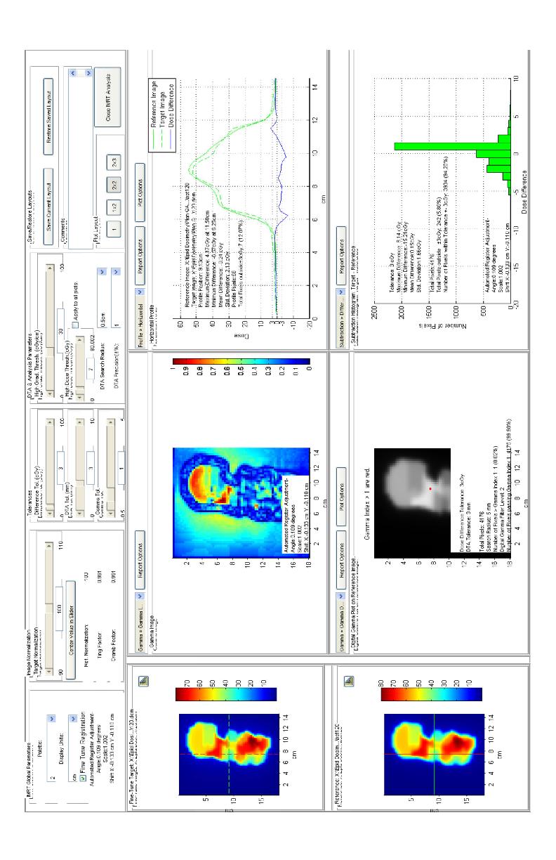
49 points such as template registration or common isocenter registration are built into RIT113. Template registration, as may be inferred, uses a template to apply to points in both the measured and calculated dose images. Isocenter registration works by assuming that the images have the same isocenter and scaling and the software then chooses points a set distance off center for both dose maps Image analysis All analysis of IMRT and VMAT dose distributions were carried out using gamma analysis in RIT. Tolerances of 3mm and 3% were chosen for gamma calculation with a gamma threshold of 1. Only points registering more than 7% of the dose delivered were analyzed in order to more accurately represent dose agreement. Detailed reports were generated for each image analyzed and an example of one of these reports is given in Figure

50 Figure 2-7 Example Image Analysis 39
51 Chapter 3 Results 3.1 Portal Dose Image Calibration results Results of the portal dose image calibration show good agreement of the predicted portal dose images and water tank profiles. Normalization to a central axis point was required in most instances to achieve the best agreement between profiles. It is considered that normalization is required to correct for the depth and effective depth of the scans being different. The water scan being taken at 1.5cm and the imager plane at a shallower physical depth (.8cm) but a deeper effective depth (1.8cm). The image below shows a non-normalized result for the 10x10 scan. There is significant disagreement between the profiles on the field edge. This can be explained by the dose averaging effects of the chamber traversing the step gradient regions of the field edge. Dose averaging is due to the ion chamber having a finite volume resulting in the charge collected at given point being representative to the average charge liberated in the entire volume. This effect is most noticeable in areas of steep gradients such as field edges where the charge liberated on leading side of the chamber is much larger that the trailing side. The effect as seen here is broadened profile, an effect largely absent from the portal imager profile because of the very small size of the 40

52 individual detectors. Below is an example comparison of a beam profile taken using the calibrated image from the TrueBEAM treatment console using RIT compared against a corresponding golden beam data water tank profile. Figure 3-1 Profile Comparison between Portal Imager Obtained Profile and Water Tank Profile. The top of the three profiles is a direct comparison of the measured beam and the water tank profile for the same field size. The second profile shown is a 41
53 subtraction of the measured profile from the water tank profile and the third profile is an off axis ratio profile. The off axis profile offers a summary of the flatness and symmetry of the beam normalized to the central axis. This profile is only analyzed over the central 80% of the profile avoiding the large values present at the field s edge. A summary of the profile agreements for each field size is included in table 3-1. A clear trend is evident for nonnormalized data, showing an under response for values less than 10cmx10cm. 3-1 Dose Image Comparison with Water Tank Data for Square Fields Dose Image Comparison with Water Tank Data for Square Fields Normalized to Central Axis Point No Normalization Mean Difference Mean Difference (%) SD field size (%) SD 3x x x x x x Average Standard Dev Average Standard Deviation for each field size is large but reasonable when considering the difference between the field edges leading to short sections of the profile with large disagreement. These large disagreements are not seriously noticeable in the average dose difference because volume averaging effects are small for a greatest portion of the field. 42
54 Precent Dose Difference 3.2 Build Up results It was expected that the best agreement would occur nearest dmax, but the findings show a slightly greater value of 1.75cm for a 6 MV producing the best agreement between TPS calculated dose and portal imager captured result when examining a square 10cm x 10cm field. 6.5% 6.0% 5.5% 5.0% 4.5% 4.0% 3.5% 3.0% 2.5% 2.0% 1.5% 1.0% 0.5% 0.0% Build Up Depth in cm Figure 3-2 Absolute Dose difference between TPS calculated Square Field and Portal Imager Measured Field as a Function of Build up for 10cm x 10cm field. The location of the minimum dose difference seen in figure 3-2 above varied with field size from as low as 1.55cm for 3cm x 3cm square fields to as great as 1.8cm for 15cm x 15cm fields. 43
55 Build Up in cm x3 5x5 10x10 15x15 Field Size Figure 3-3 Build Up Depth of Absolute Dose Difference Minimum as a function of Field Size. It was observed here that a variety of factors contributed to what effective depth a planar dose file should be created at ranging from cm. Taking into account that fields sizes vary by control point and averaging less than a 10cm x 10cm field in most cases, it was found here that a buildup of 1.5cm provided excellent agreement between the calculated and measured dose distributions. 44
56 3.3 IMRT Results IMRT comparison results are tabulated in Table 3-2 below. Included are 5 separate plans designed to be delivered to varying anatomic sites. Plans were created for treatment and therefore are using proper prescriptions for the site being treated and are of high modulation. A resolution of.25cm 2 was used in most comparisons to match the criteria used for MapCHECK2 analysis. Excepting the set of beams under IMRT prostate which showed significant deviation from MapCHECK2 results and the fields were remeasured in IMRT prostate 2 nd attempt using finer resolution.1cm 2. The results of this measurement are in much better agreement with the MapCHECK2 results and these values were used in calculating the deviation mentioned above. 45
57 Table 3-2 Agreement Between Portal Imaging Plan QA Results Compared to MapCHECK2 Imager Results IMRT Prostate MapCHECK2 Results Field No. No. Passing Passing % No. Passing Passing % Points Points Points Points IMRT Prostate 2 nd Attempt Field No. No. Passing Passing % No. Passing Passing % Points Points Points Points
58 3-3 Portal Imaging Patient specific QA Results Compared to MapCHECK2 Patient specific QA Portal Imager Results MapCHECK2 Results IMRT Anus Field No. No. Passing Passing % No. Passing Passing % Points Points Points Points IMRT Stomach Field No. No. Passing Passing % No. Passing Passing % Points Points Points Points IMRT Prostate Field No. No. Passing Passing % No. Passing Passing % Points Points Points Points
59 Portal Imager Results MapCHECK2 Results IMRT Esophagus Field No. No. Passing Passing % No. Passing Passing % Points Points Points Points IMRT Lung Field No. No. Passing Passing % No. Passing Passing % Points Points Points Points fields total Avg. Passing % MapCHECK2 Avg. Passing % VMAT Results VMAT results agreed with TPS profiles less than IMRT findings. Dose normalization proved to be necessary in most cases. The contrast between no normalization results can be seen between tables 3.4 and 3.5 and amount to about a 10, 5, and 3% improvement depending on if 3mm x 3%, 4mm x 4%, or 5mm x 5% thresholds were being used respectively. 48
60 3-4 Absolute Plan Verification Results Pancreas VMAT Plan Pancreas Single Arc CCW No Normalization. No. of No. of pixels passing analyzed pixels DTA,DD Tolerance for gamma calculation; gamma index = 1 % Passing Rate 3mm, 3% mm, 4% mm, 5% Average Passing Rate Table 3-5 Pancreas Single Arc Normalized to Max Dose Point Pancreas Single Arc CCW Normalized to Max Dose Point of profile. DTA,DD Tolerance for gamma calculation; gamma index = 1 No. of pixels analyzed No. of passing pixels % Passing Rate 3mm, 3% mm, 4% mm, 5% Average Passing Rate Stomach, Single Arc Normalized to Max Dose Point Stomach Single Arc CCW Normalized to center point of profile. DTA,DD Tolerance for gamma calculation; gamma index = 1 No. of pixels analyzed No. of passing pixels % Passing Rate 2mm, 2% mm, 3% mm, 4% mm, 5%
61 3-7 Arbitrary Arc Normalized to Max Dose Point Arbitrary Single Arc CCW Normalized to center point of profile. DTA,DD Tolerance for gamma calculation; gamma index = 1 No. of pixels analyzed No. of passing pixels % Passing Rate 2mm, 2% mm, 3% mm,4% mm, 5% Data Summery Initial calibration of the EPID was successful showing in many cases good agreement with calculated distribution. Comparison water tank data shows good agreement in beam shape but normalization is required outside of 10x10 fields. Choosing an optimal buildup depth would require averaging with weighting the field area of the beam being examined but generally any value 1.5 and 1.8 show to offer good agreement when verifying plans. Average difference in percentage of passing points between the EPID verified results and MapCHECK2 verified results over all fields analyzed was.013% ± 2.58%. VMAT total results showed a total passing rate of 98.6% ± 1.33% for the 3 arcs tested. A commercial VMAT QA phantom was not available and a comparison against a known good verification system could not be performed. 50
62 Chapter 4 Discussion 4.1 Comparison to other research Results from this study find an average agreement for IMRT fields to be 97.8% for all fields examined using the portal imager. The findings here are in good agreement with the findings of other studies such as Bailey et al., who s results showed an agreement of 98.1% (Bailey et al 2012) and are shown in Table 4-1. In all IMRT measurements a comparison measurement was taken to MapCHECK2 results for the same plan under very similar conditions. While agreement with MapCHECK2 results does help build confidence in the method devised here it is only intended to prove the concept is comparable to a commonly used QA method. Comparing this to MapCHECK2 results it is necessary to consider the possibility that in some cases EPID QA as described here can be a better method of plan verification. A particular example may be in the cases of small fields. Small fields offer very few points for analysis using MapCHECK2 and the extra resolution of the imager can offer much more detail and possible a better evaluation of the field performance. 51
63 4-1 Comparison with Other IMRT Portal Imaging QA Results Agreement with Statistics Agreement with TPS TPS ( Bailey et al. 2012) Prostate Mean Std Dev Min Max Head and Neck Mean Std Dev Min Max VMAT results using the 3mm and 3% criteria produce and average agreement with the TPS calculation of Comparing this to similar data found by Baily et al. showing an agreement of 96.75% the results here seem slightly better. It must be noted that VMAT verification in this study required normalization to achieve such agreement and a separate evaluation of the results as compared to a known good VMAT QA method was not possible because such a device was not available for use in this study. 4.2 Limitation of patient specific QA using portal imaging Several limitations must be acknowledged when considering plan verification using the methods in this study. First, portal dosimetry for fields greater 15cm is a known limitation with Varian portal dosimetry, as stated in the customer release note Portal Dosimetry Pre-Configuration package (Varian 52
64 Medical Systems). Second, portal imagers show no dose rate dependency until saturation is approached which occurs shortly after 600mu/min meaning that EPID dosimetry cannot be used for flattening filter free treatments as it fails to correctly tally charge collected at very high dose rate. Third, the geometry between the portal imager and the treatment beam is fixed orthogonally. There is no opportunity to examine the beam on an inline direction and no simple way to verify the gantry position or speed. Overcoming the difficulty in determining gantry rotation rate is a difficult task and is accomplished in some third party device by using a gantry mounted gyroscope to log gantry position as a function of time. Some methods do not consider gantry rate modulation an do so on the idea that gantry rotation rate is verified in monthly test and not explicitly required for plan verification. 53
65 Chapter 5 Conclusions EPIDs have been shown previously to meet the requirements of 2d dosimeter panels for patient specific QA. The qualities of asi detectors, having high spatial resolution, large area, stability, large dynamic range, and real time dose acquisition capabilities certainly make it an attractive option for patient specific QA. The finding in this study suggests the same. The average agreement with planar dose files was greater than 97% for all IMRT fields analyzed and it is the findings of this study that EPIDs are capable for implementation in IMRT plan verification. Cases exist where MV imaging may offer better plan verification than commonly used methods such as MapCHECK2 (Sun Nuclear TM, or devices alike). Taking small fields as an example, the extra resolution offered by the portal imager produced much more complete verification due to the increased statistics and allows for a better view of the distribution as a whole. The buildup that produced the best agreement between the measured profile and a computed planar dose file was found to have some field size dependence. Due to this dependence it is questionable if any single build up thickness can best be used on all IMRT fields. It may be possible to take a weighted average of the open field size for each control point of a IMRT beam 54
66 to select a proper build up on a beam to beam basis. However it was found empirically that a value of 1.5cm produced excellent agreement with the IMRT fields analyzed in this study. Good agreement was found between the planar composite dose files created using the in-house script developed here and the EPID dose measurements taken during the delivery of arc treatments. This verification of dose distribution offers a good verification of many of the elements that define VMAT plans and the findings of this study show that VMAT can be verified using the methods described here but must be accompanied with an absolute measurement. Some limitations exist for the methods employed here to verify plans. Fields greater that 15cm x15cm produces significantly degraded dose resolution due to filed size dependence and these fields should be avoided. Though dose resolution is considered good for most IMRT and VMAT plans it is recommended that dose distribution analyzed as described here be accompanied with an absolute dose measurement. The lack of gantry rotation rate verification during the delivery of VMAT fields is an area that may require additional QA as well and should be considered when using the portal imager for plan verification of VMAT plans. 55
67 References 1. Bailey, Daniel W., et al. "EPID dosimetry for pretreatment quality assurance with two commercial systems." Journal of Applied Clinical Medical Physics13.4 (2012). 2. Bogdanich, Walt. "THE RADIATION BOOM Radiation Offers New Cures, and Ways to Do Harm." New York Times , New York Edition 3. Chen, Josephine, et al. "Calibration of an amorphous-silicon flat panel portal imager for exit-beam dosimetry." Medical physics 33 (2006): Connell, Philip P., Stephen J. Kron, and Ralph R. Weichselbaum. "Relevance and irrelevance of DNA damage response to radiotherapy." DNA repair 3.8 (2004): Ezzell, Gary A., et al. "IMRT commissioning: multiple institution planning and dosimetry comparisons, a report from AAPM Task Group 119." Medical physics36 (2009): Geoghegan, S. (2007). Scripting on the Pinnacle³3 treatment planning system. 7. Huang, Yen-Cho, et al. "Clinical practice and evaluation of electronic portal imaging device for VMAT quality assurance." Medical Dosimetry (2012). 8. Ju, Tao, et al. "Geometric interpretation of the γ dose distribution comparison technique: Interpolation-free calculation." Medical physics 35 (2008): Lee, Christopher, et al. "A simple approach to using an amorphous silicon EPID to verify IMRT planar dose maps." Medical physics 36 (2009): Low, Daniel A., and James F. Dempsey. "Evaluation of the gamma dose distribution comparison method." Medical Physics 30 (2003):
68 11. Low, Daniel A., et al. "A technique for the quantitative evaluation of dose distributions." Medical physics 25 (1998): Low, Daniel A., et al. "Dosimetry tools and techniques for IMRT." Med Phys38.3 (2011): Luchka, K., and S. Pistorius. "Dosimetric investigation and portal dose image prediction using an amorphous silicon electronic portal imaging device." Medical physics 28 (2001): Martens, Chantal, et al. "Underdosage of the upper-airway mucosa for small fields as used in intensity-modulated radiation therapy: A comparison between radiochromic film measurements, Monte Carlo simulations, and collapsed cone convolution calculations." Medical physics 29 (2002): Nelms, Benjamin E., Karl H. Rasmussen, and Wolfgang A. Tome. "Evaluation of a fast method of EPID-based dosimetry for intensity modulated radiation therapy." Journal of applied clinical medical physics/american College of Medical Physics 11.2 (2010): Nelms, Benjamin Edward, and Jeff A. Simon. "A survey on IMRT QA analysis." Journal of applied clinical medical physics 8.3 (2007). 17. Oliver, Michael, Will Ansbacher, and Wayne A. Beckham. "Comparing planning time, delivery time and plan quality for IMRT, RapidArc and TomoTherapy." Journal of Applied Clinical Medical Physics 10.4 (2009). 18. Otto, Karl. "Volumetric modulated arc therapy: IMRT in a single gantry arc." Medical physics 35 (2008): Rowbottom, C. G., et al. "Investigation into the Pinnacle³ SmartArc Module for VMAT Planning." World Congress on Medical Physics and Biomedical Engineering, September 7-12, 2009, Munich, Germany. Springer Berlin Heidelberg, Van Esch, Ann, Tom Depuydt, and Dominique Pierre Huyskens. "The use of an asi-based EPID for routine absolute dosimetric pretreatment verification of dynamic IMRT fields." Radiotherapy and oncology 71.2 (2004): Varian Medical Systems,. Varian Medical Systems. Portal Dosimetry Pre-Configuration Package Customer Release Note. Palo Alto Ca:, Print. 57
69 22. Wienkav,. "Dose Calibration of as500.". N.p.. Web. 28 May < m>. 58
70 Appendence Appendix A Example W2CAD file format $NUMS 005 $STOM # # Comment: # Detector: CC 13 Field # Operator: # %VERSION 02 %DATE %DETY CHA %BMTY PHO %FLSZ 400*400 %TYPE DPR %AXIS D 59
71 %PNTS 993 %STEP 007 %SSD 1000 %DPTH 015 < > < > < > < > < > < > < >\ < > < > < > < > < > 60
72 < > < > < > < > $ENOM $STOM 61
73 Appendix B Analog Arc IMRT beam creation script //Save Name of Arc Store.StringAt.ArcBeingComplied = TrialList.Current.BeamList.Current.Name; //Begin wait Message "WaitMessage = ""Computing Composite Beam..."";" "//Rename arc ""working"" while script is ran" "TrialList.Current.BeamList.Current.Name = ""Working"";" "//Create PlanarComp beam by calling on second script ""BeamTemplate.Script.p3rtp""" "ExecuteNow = ""/home/p3rtp/justinw/beamtemplate.script.p3rtp"";" //Name PlannarComp beam "TrialList.Current.BeamList.Current.Name = ""PlanarComp"";" "//Write out Arc Controlpoint list to file ""CP.dat"";" "TrialList.Current.BeamList.Working.CPManager.CPManagerObject.Save = ""/home/p3rtp/justinw/cp.dat"";" "//Concatenate ""Copy2PlanarHeader"",""CP.dat"" and ""Copy2PlanarFooter"" in to file ""CPData.Script.p3rtp"" This new file is a 62
74 script that modifies beam PlanarComp to insert the control points from the arc." "SpawnCommand = ""cat /home/p3rtp/justinw/copy2planarheader /home/p3rtp/justinw/cp.dat /home/p3rtp/justinw/copy2planarfooter > /home/p3rtp/justinw/cpdata.script.p3rtp"";" //Execute CPData Script to modifiy Planar Comp beam. "ExecuteNow = ""/home/p3rtp/justinw/cpdata.script.p3rtp"";" "//Set Gantry posistion of all control points added to planar comp to 0 degrees by calling on script ""SetGantryto0.dat""" "TrialList.Current.BeamList.PlanarComp.CPManager.CPManagerObject.Co ntrolpointlist.childreneachcurrent.#""@"".script.executenow = ""/home/p3rtp/justinw/setgantryto0.dat"";" "//Copy parameters of Arc to Planar Beam such as energy, associated prescription etc.." TrialList.Current.BeamList.PlanarComp.IsocenterName = TrialList.Current.BeamList.Working.IsocenterName; TrialList.Current.BeamList.PlanarComp.PrescriptionName = TrialList.Current.BeamList.Working.PrescriptionName ; 63
75 TrialList.Current.BeamList.PlanarComp.UsePoiForPrescriptionPoint = TrialList.Current.BeamList.Working.UsePoiForPrescriptionPoint; //TrialList.Current.BeamList.PlanarComp.PrescriptionPointName = TrialList.Current.BeamList.Working.PrescriptionPointName; TrialList.Current.BeamList.PlanarComp.SpecifyDosePerMuAtPrescriptionPo int = TrialList.Current.BeamList.Working.SpecifyDosePerMuAtPrescriptionPoint; TrialList.Current.BeamList.PlanarComp.DosePerMuAtPrescriptionPoint = TrialList.Current.BeamList.Working.DosePerMuAtPrescriptionPoint; TrialList.Current.BeamList.PlanarComp.Modality = TrialList.Current.BeamList.Working.Modality; TrialList.Current.BeamList.PlanarComp.MachineEnergyName = TrialList.Current.BeamList.Working.MachineEnergyName; TrialList.Current.BeamList.PlanarComp.Machine.PhotonEnergyList.Curren t = TrialList.Current.BeamList.Working.Machine.PhotonEnergyList.Current; //Return Arc Name to intial setting TrialList.Current.BeamList.Working.Name = Store.At.ArcBeingComplied.String; //Clean up uneeded files 64
76 SpawnCommandNoWait = "rm /home/p3rtp/justinw/cp.dat*"; SpawnCommand = "y"; //Turn wait message off WaitMessageOff = ; Beam Creation Script Header TrialList.Current.BeamList.PlanarComp = { Name = "PlanarComp"; IsocenterName = "POI_1"; PrescriptionName = "Prescription_1"; UsePoiForPrescriptionPoint = 1; PrescriptionPointName = "POI_1"; PrescriptionPointDepth = 5; PrescriptionPointXOffset = 0; PrescriptionPointYOffset = 0; SpecifyDosePerMuAtPrescriptionPoint = 0; DosePerMuAtPrescriptionPoint = 1; MachineNameAndVersion = "TrueBeamSN1372E: :25:13"; Modality = "Photons"; MachineEnergyName = "6 MV"; DesiredLocalizerName = "Laser"; ActualLocalizerName = "Laser"; DisplayLaserMotion = "Table"; 65
77 SetBeamType = "Step & Shoot MLC"; PrevBeamType = "Step & Shoot MLC"; ComputationVersion = "Unknown"; CPManager ={ CPManagerObject ={ Set the Gantry for all children to 0 script TrialList.Current.BeamList.PlanarComp.CPManager.CPManagerObject. ControlPointList.Current.Gantry = 0; 66
78 Appendix C Example RIT Results 67
79 68

80 69
81 70
IMRT and VMAT Patient Specific QA Using 2D and 3D Detector Arrays
 IMRT and VMAT Patient Specific QA Using 2D and 3D Detector Arrays Sotiri Stathakis Outline Why IMRT/VMAT QA AAPM TG218 UPDATE Tolerance Limits and Methodologies for IMRT Verification QA Common sources
A comparative analysis for verification of IMRT and VMAT treatment plans using a 2-D and 3-D diode array
 The University of Toledo The University of Toledo Digital Repository Theses and Dissertations 2014 A comparative analysis for verification of IMRT and VMAT treatment plans using a 2-D and 3-D diode array
Volumetric Modulated Arc Therapy - Clinical Implementation. Outline. Acknowledgement. History of VMAT. IMAT Basics of IMAT
 Volumetric Modulated Arc Therapy - Clinical Implementation Daliang Cao, PhD, DABR Swedish Cancer Institute, Seattle, WA Acknowledgement David M. Shepard, Ph.D. Muhammad K. N. Afghan, Ph.D. Fan Chen, Ph.D.
THE WIRELESS PHANTOM PERFORM ACCURATE PATIENT QA IN LESS TIME THAN EVER!
 THE WIRELESS PHANTOM PERFORM ACCURATE PATIENT QA IN LESS TIME THAN EVER! Confidence in complex treatments Modern radiation therapy uses complex plans with techniques such as IMRT, VMAT and Tomotherapy.
Basic Radiation Oncology Physics
 Basic Radiation Oncology Physics T. Ganesh, Ph.D., DABR Chief Medical Physicist Fortis Memorial Research Institute Gurgaon Acknowledgment: I gratefully acknowledge the IAEA resources of teaching slides
4 Measurement. and Analysis. 4.1 Overview and Underlying Principles 4-1
 Measurement and Analysis.1 Overview and Underlying Principles.1.1 Introductory Remarks The physics and setup for film dosimetry have been described in the previous chapters. The measurement setup for IMRT
Investigation of tilted dose kernels for portal dose prediction in a-si electronic portal imagers
 Investigation of tilted dose kernels for portal dose prediction in a-si electronic portal imagers Krista Chytyk MSc student Supervisor: Dr. Boyd McCurdy Introduction The objective of cancer radiotherapy
Raising the Bar in IMRT QA
 MapCHECK 2TM Raising the Bar in IMRT QA The leader in quick and precise measurement of modulated radiotherapy beams Benefits Proven solution for film-less rotational delivery and IMRT QA - More than 1500
MapCHECK 2 & 3DVH The Gold Standard for 2D Arrays
 MapCHECK 2 & 3DVH The Gold Standard for 2D Arrays Your Most Valuable QA and Dosimetry Tools THE GOLD STANDARD FOR 2D ARRAYS The MapCHECK 2 is the world s most selected independent 2D measurement array.
MapCHECK 2 & 3DVH. The Gold Standard for 2D Arrays
 MapCHECK 2 & 3DVH The Gold Standard for 2D Arrays Your Most Valuable QA and Dosimetry Tools THE GOLD STANDARD FOR 2D ARRAYS The MapCHECK 2 is the world s most selected independent 2D measurement array.
ADVANCING CANCER TREATMENT
 The RayPlan treatment planning system makes proven, innovative RayStation technology accessible to clinics that need a cost-effective and streamlined solution. Fast, efficient and straightforward to use,
IMSURE QA SOFTWARE FAST, PRECISE QA SOFTWARE
 QA SOFTWARE FAST, PRECISE Software for accurate and independent verification of monitor units, dose, and overall validity of standard, IMRT, VMAT, SRS and brachytherapy plans no film, no phantoms, no linac
Tomotherapy Physics. Machine Twinning and Quality Assurance. Emilie Soisson, MS
 Tomotherapy Physics Machine Twinning and Quality Assurance Emilie Soisson, MS Tomotherapy at UW- Madison Treating for nearly 5 years Up to ~45 patients a day on 2 tomo units Units twinned to facilitate
Machine and Physics Data Guide
 WWW..COM Machine and Physics Data Guide STANDARD IMAGING, INC. 3120 Deming Way Middleton, WI 53562-1461 May / 2008 2008 Standard Imaging, Inc. TEL 800.261.4446 TEL 608.831.0025 FAX 608.831.2202 www.standardimaging.com
ADVANCING CANCER TREATMENT
 3 ADVANCING CANCER TREATMENT SUPPORTING CLINICS WORLDWIDE RaySearch is advancing cancer treatment through pioneering software. We believe software has un limited potential, and that it is now the driving
A DOSIMETRIC MODEL FOR SMALL-FIELD ELECTRON RADIATION THERAPY A CREATIVE PROJECT (3 SEMESTER HOURS) SUBMITTED TO THE GRADUATE SCHOOL
 SUBMITTED TO THE GRADUATE SCHOOL") A DOSIMETRIC MODEL FOR SMALL-FIELD ELECTRON RADIATION THERAPY A CREATIVE PROJECT (3 SEMESTER HOURS) SUBMITTED TO THE GRADUATE SCHOOL IN PARTIAL FULFILLMENT OF THE REQUIREMENTS FOR THE DEGREE MASTER OF
A DOSIMETRIC MODEL FOR SMALL-FIELD ELECTRON RADIATION THERAPY A CREATIVE PROJECT (3 SEMESTER HOURS) SUBMITTED TO THE GRADUATE SCHOOL IN PARTIAL FULFILLMENT OF THE REQUIREMENTS FOR THE DEGREE MASTER OF
FAST, precise. qa software
 qa software FAST, precise Software for accurate and independent verification of monitor units, dose, and overall validity of standard, IMRT, rotational or brachytherapy plans no film, no phantoms, no linac
Photon beam dose distributions in 2D
 Photon beam dose distributions in 2D Sastry Vedam PhD DABR Introduction to Medical Physics III: Therapy Spring 2014 Acknowledgments! Narayan Sahoo PhD! Richard G Lane (Late) PhD 1 Overview! Evaluation
Transitioning from pencil beam to Monte Carlo for electron dose calculations
 Transitioning from pencil beam to Monte Carlo for electron dose calculations Jessie Huang-Vredevoogd (jyhuang4@wisc.edu) University of Wisconsin NCC AAPM October 12, 2019 1 Topics to cover Background RayStation
Dynalog data tool for IMRT plan verification
 Dynalog data tool for IMRT plan verification Poster No.: R-0051 Congress: 2014 CSM Type: Scientific Exhibit Authors: V. Sashin; FOOTSCRAY/AU Keywords: Computer applications, Radiation physics, Experimental,
Acknowledgments. Ping Xia, Ph.D., UCSF. Pam Akazawa, CMD, UCSF. Cynthia Chuang, Ph.D., UCSF
 Page 1 Quality Assurance of IMRT Delivery Systems - Siemens Lynn J. Verhey, Ph.D. Professor and Vice-Chair UCSF Dept. of Radiation Oncology AAPM 22 Annual Meeting, Montreal Acknowledgments Ping Xia, Ph.D.,
A secondary monitor unit calculation algorithm using superposition of symmetric, open fields for IMRT plans
 Louisiana State University LSU Digital Commons LSU Master's Theses Graduate School 2013 A secondary monitor unit calculation algorithm using superposition of symmetric, open fields for IMRT plans Adam
An Automated Image-based Method for Multi-Leaf Collimator Positioning Verification in Intensity Modulated Radiation Therapy
 An Automated Image-based Method for Multi-Leaf Collimator Positioning Verification in Intensity Modulated Radiation Therapy Chenyang Xu 1, Siemens Corporate Research, Inc., Princeton, NJ, USA Xiaolei Huang,
Follow this and additional works at:
 The University of Toledo The University of Toledo Digital Repository Theses and Dissertations 2010 Implementation of the Dosimetry Check software package in computing 3D patient exit dose through generation
2D DOSE MEASUREMENT USING A FLAT PANEL EPID
 2D DOSE MEASUREMENT USING A FLAT PANEL EPID by Seng Boh Lim B.A.Sc. (Hons.), University of British Columbia, 1994 M.A.Sc., University of British Colombia, 1996 M.Eng, University of British Columbia, 2002
Disclosure. Outline. Acknowledgments. Ping Xia, Ph.D., Page 1. LINAC and MLC QA for IMRT. Received research support from Siemens Medical Solutions
 LINAC and MLC QA for IMRT Ping Xia, Ph.D., Department of Radiation Oncology Disclosure Received research support from Siemens Medical Solutions University of California San Francisco Therapy Series (SAM)
Integrated proton-photon treatment planning
 Pinnacle 3 Proton Planning Integrated proton-photon treatment planning Philips Pinnacle 3 Proton Planning specifications Pinnacle 3 Proton Planning is designed to simplify treatment planning for proton
3DVH : SUN NUCLEAR On The Accuracy Of The corporation Planned Dose Perturbation Algorithm Your Most Valuable QA and Dosimetry Tools *Patent Pending
 3DVH : On The Accuracy Of The Planned Dose Perturbation Algorithm SUN NUCLEAR corporation Your Most Valuable QA and Dosimetry Tools *Patent Pending introduction State-of-the-art IMRT QA of static gantry
TEPZZ Z754_7A_T EP A1 (19) (11) EP A1 (12) EUROPEAN PATENT APPLICATION. (51) Int Cl.: A61N 5/10 ( )
 (11) EP A1 (12) EUROPEAN PATENT APPLICATION. (51) Int Cl.: A61N 5/10 ( )") (19) TEPZZ Z74_7A_T (11) EP 3 07 417 A1 (12) EUROPEAN PATENT APPLICATION (43) Date of publication: 0..16 Bulletin 16/ (1) Int Cl.: A61N / (06.01) (21) Application number: 16163147.8 (22) Date of filing:
(19) TEPZZ Z74_7A_T (11) EP 3 07 417 A1 (12) EUROPEAN PATENT APPLICATION (43) Date of publication: 0..16 Bulletin 16/ (1) Int Cl.: A61N / (06.01) (21) Application number: 16163147.8 (22) Date of filing:
NEW METHOD OF COLLECTING OUTPUT FACTORS FOR COMMISSIONING LINEAR ACCELERATORS WITH SPECIAL EMPHASIS
 NEW METHOD OF COLLECTING OUTPUT FACTORS FOR COMMISSIONING LINEAR ACCELERATORS WITH SPECIAL EMPHASIS ON SMALL FIELDS AND INTENSITY MODULATED RADIATION THERAPY by Cindy D. Smith A Thesis Submitted to the
Facility Questionnaire PART I (General Information for 3DCRT and IMRT)
") Facility Questionnaire PART I (General Information for 3DCRT and IMRT) The following items are required before you can enter cases on any RTOG protocol that requires data submission to the Image-Guided
Facility Questionnaire PART I (General Information for 3DCRT and IMRT) The following items are required before you can enter cases on any RTOG protocol that requires data submission to the Image-Guided
Delta 4 PT. True Volumetric Pre-treatment Verification. The difference is clear
 Delta 4 PT True Volumetric Pre-treatment Verification The difference is clear ScandiDos innovators in advanced volumetric dosimetry solutions ScandiDos ScandiDos is the innovative company that introduced
ICARO Vienna April Implementing 3D conformal radiotherapy and IMRT in clinical practice: Recommendations of IAEA- TECDOC-1588
 ICARO Vienna April 27-29 2009 Implementing 3D conformal radiotherapy and IMRT in clinical practice: Recommendations of IAEA- TECDOC-1588 M. Saiful Huq, Ph.D., Professor and Director, Dept. of Radiation
New Technology in Radiation Oncology. James E. Gaiser, Ph.D. DABR Physics and Computer Planning Charlotte, NC
 New Technology in Radiation Oncology James E. Gaiser, Ph.D. DABR Physics and Computer Planning Charlotte, NC Technology s s everywhere From the imaging chain To the planning system To the linac To QA..it..it
Assesing multileaf collimator effect on the build-up region using Monte Carlo method
 Pol J Med Phys Eng. 2008;14(3):163-182. PL ISSN 1425-4689 doi: 10.2478/v10013-008-0014-0 website: http://www.pjmpe.waw.pl M. Zarza Moreno 1, 2, N. Teixeira 3, 4, A. P. Jesus 1, 2, G. Mora 1 Assesing multileaf
Hugues Mailleux Medical Physics Department Institut Paoli-Calmettes Marseille France. Sunday 17 July 2016
 Hugues Mailleux Medical Physics Department Institut Paoli-Calmettes Marseille France Sunday 17 July 2016 AGENDA 1. Introduction 2. Material 3. Optimization process 4. Results 5. Comments 6. Conclusion
Evaluation of 3D Gamma index calculation implemented in two commercial dosimetry systems
 University of Wollongong Research Online Faculty of Engineering and Information Sciences - Papers: Part A Faculty of Engineering and Information Sciences 2015 Evaluation of 3D Gamma index calculation implemented
Quick Reference Datasheet For All RIT113 Packages
 Quick Reference Datasheet For All RIT113 Packages For Rotational Therapies, IMRT & TG142 Highlights and selected product information only. A complete TG142 brochure is available. For more information on
Use of a commercial ion chamber detector array for the measurement of high spatial resolution photon beam profiles
 Received: 17 January 2018 Revised: 27 August 2018 Accepted: 31 August 2018 DOI: 10.1002/acm2.12466 TECHNICAL NOTE Use of a commercial ion chamber detector array for the measurement of high spatial resolution
Preface. Med. Phys. 35(9), , Mechanical QA. Radiation Survey Mechanical tests Light radiation Table, Collimator, Gantry Jaws.
, , Mechanical QA. Radiation Survey Mechanical tests Light radiation Table, Collimator, Gantry Jaws.") AAPM-SAM-2012-Das (1) Beam Data Collection and Commissioning for Linear Accelerators: Technical Considerations and Recommendations Preface Indra J. Das, PhD, FAAPM, FACR, FASTRO Department of Radiation
AAPM-SAM-2012-Das (1) Beam Data Collection and Commissioning for Linear Accelerators: Technical Considerations and Recommendations Preface Indra J. Das, PhD, FAAPM, FACR, FASTRO Department of Radiation
DAILY LINAC QA BEAM QA
 BEAM QA DAILY LINAC QA The QA BeamChecker Plus allows for fast, reliable, and uncomplicated daily QA of Varian, Elekta, Siemens, and Accuray Treatment Machines. The QA BeamChecker Plus is specifically
Dose Calculation and Optimization Algorithms: A Clinical Perspective
 Dose Calculation and Optimization Algorithms: A Clinical Perspective Daryl P. Nazareth, PhD Roswell Park Cancer Institute, Buffalo, NY T. Rock Mackie, PhD University of Wisconsin-Madison David Shepard,
8/4/2016. Emerging Linac based SRS/SBRT Technologies with Modulated Arc Delivery. Disclosure. Introduction: Treatment delivery techniques
 Emerging Linac based SRS/SBRT Technologies with Modulated Arc Delivery Lei Ren, Ph.D. Duke University Medical Center 2016 AAPM 58 th annual meeting, Educational Course, Therapy Track Disclosure I have
Basics of treatment planning II
 Basics of treatment planning II Sastry Vedam PhD DABR Introduction to Medical Physics III: Therapy Spring 2015 Dose calculation algorithms! Correction based! Model based 1 Dose calculation algorithms!
3DVH FAQs. What is PDP questions
 3DVH FAQs What is PDP questions 1. Explain the PDP in layman terms. How does PDP work? a. Very simply, PDP uses measured diode data, and compares it to the expected treatment plan data. The differences
Real-time monitoring of linac performance using RT plans and logfiles
 Real-time monitoring of linac performance using RT plans and logfiles NCCAAPM Wisconsin Dells 7 April 2017 Mark Wiesmeyer, PhD, DABR Technical Product Manager Technical talk with insights and results based
Advanced Radiotherapy
 Advanced Radiotherapy IBA Concept for IMRT Verification Dr. Lutz Müller 1 IMRT Verification BIS BIS ADAS Fluence Model Delivered fluence Target Volume Constraints Inverse Backprojection Fluence Map Leaf
Dose Distributions. Purpose. Isodose distributions. To familiarize the resident with dose distributions and the factors that affect them
 Dose Distributions George Starkschall, Ph.D. Department of Radiation Physics U.T. M.D. Anderson Cancer Center Purpose To familiarize the resident with dose distributions and the factors that affect them
UNIVERSITY OF SOUTHAMPTON
 UNIVERSITY OF SOUTHAMPTON PHYS2007W1 SEMESTER 2 EXAMINATION 2014-2015 MEDICAL PHYSICS Duration: 120 MINS (2 hours) This paper contains 10 questions. Answer all questions in Section A and only two questions
Code of practice: Create a verification plan for OCTAVIUS Detector 729 in Philips Pinnacle³
 Technical Note D655.208.03/00 Code of practice: Create a verification plan for OCTAVIUS Detector 729 in There are basically three ways to carry out verification of IMRT fluences. For all options, it is
Monaco VMAT. The Next Generation in IMRT/VMAT Planning. Paulo Mathias Customer Support TPS Application
 Monaco VMAT The Next Generation in IMRT/VMAT Planning Paulo Mathias Customer Support TPS Application 11.05.2011 Background What is Monaco? Advanced IMRT/VMAT treatment planning system from Elekta Software
Qalitätssicherung an Multileafkollimatoren. Dr. Lutz Müller Würzburg jan 2004
 Qalitätssicherung an Multileafkollimatoren Dr. Lutz Müller Würzburg jan 2004 IMRT Verification - present Target Volume Constraints Inverse Planning Algorithm Fluence Map Leaf Sequencer Leaf & Gantry sequence
A SYSTEM OF DOSIMETRIC CALCULATIONS
 A SYSTEM OF DOSIMETRIC CALCULATIONS INTRODUCTION Dose calculation based on PDD and TAR have Limitations The dependence of PDD on SSD Not suitable for isocentric techniques TAR and SAR does not depend on
TPS COMMISSIONING. Laurence Court University of Texas MD Anderson Cancer Center 4/3/2017 1
 TPS COMMISSIONING Laurence Court University of Texas MD Anderson Cancer Center 4/3/2017 1 Conflicts of interest Court receives funding from NIH, CPIRT, Varian and Elekta 4/3/2017 2 Resources your first
Analysis of Radiation Transport through Multileaf Collimators Using BEAMnrc Code
 American Journal of Biomedical Engineering 216, 6(4): 124-131 DOI: 1.5923/j.ajbe.21664.3 Analysis of Radiation Transport through Multileaf Collimators Using BEAMnrc Code Ankit Kajaria 1,*, Neeraj Sharma
Proton dose calculation algorithms and configuration data
 Proton dose calculation algorithms and configuration data Barbara Schaffner PTCOG 46 Educational workshop in Wanjie, 20. May 2007 VARIAN Medical Systems Agenda Broad beam algorithms Concept of pencil beam
IAEA-TECDOC-1583 Commissioning of Radiotherapy Treatment Planning Systems: Testing for Typical External Beam Treatment Techniques
 IAEA-TECDOC-1583 Commissioning of Radiotherapy Treatment Planning Systems: Testing for Typical External Beam Treatment Techniques Report of the Coordinated Research Project (CRP) on Development of Procedures
7/31/2011. Learning Objective. Video Positioning. 3D Surface Imaging by VisionRT
 CLINICAL COMMISSIONING AND ACCEPTANCE TESTING OF A 3D SURFACE MATCHING SYSTEM Hania Al-Hallaq, Ph.D. Assistant Professor Radiation Oncology The University of Chicago Learning Objective Describe acceptance
Megan A. Wood, M.S. Under the direction of Larry DeWerd, Ph.D. University of Wisconsin Medical Radiation Research Center (UWMRRC)
") Megan A. Wood, M.S. Under the direction of Larry DeWerd, Ph.D. University of Wisconsin Medical Radiation Research Center (UWMRRC) NCCAAPM Spring Meeting May 3, 2013 Introduction FFF background Project
Megan A. Wood, M.S. Under the direction of Larry DeWerd, Ph.D. University of Wisconsin Medical Radiation Research Center (UWMRRC) NCCAAPM Spring Meeting May 3, 2013 Introduction FFF background Project
Helical Tomotherapy Qualitative dose Delivery Verification
 University of Tennessee, Knoxville Trace: Tennessee Research and Creative Exchange University of Tennessee Honors Thesis Projects University of Tennessee Honors Program 5-2003 Helical Tomotherapy Qualitative
M.Sc. Thesis - E. Nichita; McMaster University Medical Physics and Applied Radiation Sciences IMRT DOSE VERIFICATION WITH ELECTRONIC PORTAL IMAGERS
 IMRT DOSE VERIFICATION WITH ELECTRONIC PORTAL IMAGERS A STUDY OF IMRT PRE-TREATMENT DOSE VERIFICATION USING A-SI ELECTRONIC PORTAL IMAGING DEVICES By ELEODOR NICHITA, B.SC., M.SC., PH.D. A Thesis Submitted
Initial Clinical Experience with 3D Surface Image Guidance
 Initial Clinical Experience with 3D Surface Image Guidance Amanda Havnen-Smith, Ph.D. Minneapolis Radiation Oncology Ridges Radiation Therapy Center Burnsville, MN April 20 th, 2012 Non-funded research
Medical Dosimetry 37 (2012) Medical Dosimetry. journal homepage:
 Medical Dosimetry. journal homepage:") Medical Dosimetry 37 (2012) 53-60 Medical Dosimetry journal homepage: www.meddos.org Characterization of responses of 2d array seven29 detector and its combined use with octavius phantom for the patient-specific
Medical Dosimetry 37 (2012) 53-60 Medical Dosimetry journal homepage: www.meddos.org Characterization of responses of 2d array seven29 detector and its combined use with octavius phantom for the patient-specific
Monte Carlo Simulation for Neptun 10 PC Medical Linear Accelerator and Calculations of Electron Beam Parameters
 Monte Carlo Simulation for Neptun 1 PC Medical Linear Accelerator and Calculations of Electron Beam Parameters M.T. Bahreyni Toossi a, M. Momen Nezhad b, S.M. Hashemi a a Medical Physics Research Center,
Use of Monte Carlo modelling in radiotherapy linac design. David Roberts, PhD Senior Physicist Elekta
 Use of Monte Carlo modelling in radiotherapy linac design David Roberts, PhD Senior Physicist Elekta Contents Overview of Elekta What we do Where we use Monte Carlo Codes and resources Example : Agility
7/29/2017. Making Better IMRT Plans Using a New Direct Aperture Optimization Approach. Aim of Radiotherapy Research. Aim of Radiotherapy Research
 Making Better IMRT Plans Using a New Direct Aperture Optimization Approach Dan Nguyen, Ph.D. Division of Medical Physics and Engineering Department of Radiation Oncology UT Southwestern AAPM Annual Meeting
Iterative regularization in intensity-modulated radiation therapy optimization. Carlsson, F. and Forsgren, A. Med. Phys. 33 (1), January 2006.
, January 2006.") Iterative regularization in intensity-modulated radiation therapy optimization Carlsson, F. and Forsgren, A. Med. Phys. 33 (1), January 2006. 2 / 15 Plan 1 2 3 4 3 / 15 to paper The purpose of the paper
Iterative regularization in intensity-modulated radiation therapy optimization Carlsson, F. and Forsgren, A. Med. Phys. 33 (1), January 2006. 2 / 15 Plan 1 2 3 4 3 / 15 to paper The purpose of the paper
8/2/2017. PerFRACTION from Sun Nuclear Automated Transit Dosimetry for In-Vivo QA
 PerFRACTION from Sun Nuclear Automated Transit Dosimetry for In-Vivo QA Jennifer R. Clark, M.S., DABR Conflict of Interest Statement: I am an employee of Sun Nuclear Corporation Outline: Platform overview
Data. ModuLeaf Mini Multileaf Collimator Precision Beam Shaping for Advanced Radiotherapy
 Data ModuLeaf Mini Multileaf Collimator Precision Beam Shaping for Advanced Radiotherapy ModuLeaf Mini Multileaf Collimator Precision Beam Shaping for Advanced Radiotherapy The ModuLeaf Mini Multileaf
UNCOMPROMISING QUALITY
 ION CHAMBERS UNCOMPROMISING QUALITY Designed with over 30 years of scientific integrity for a broad range of dosimetry measurements in diverse radiation beams Farmer-type Chambers For absolute dosimetry
An Investigation of a Model of Percentage Depth Dose for Irregularly Shaped Fields
 Int. J. Cancer (Radiat. Oncol. Invest): 96, 140 145 (2001) 2001 Wiley-Liss, Inc. Publication of the International Union Against Cancer An Investigation of a Model of Percentage Depth Dose for Irregularly
The team. Disclosures. Ultrasound Guidance During Radiation Delivery: Confronting the Treatment Interference Challenge.
 Ultrasound Guidance During Radiation Delivery: Confronting the Treatment Interference Challenge Dimitre Hristov Radiation Oncology Stanford University The team Renhui Gong 1 Magdalena Bazalova-Carter 1
Modulation factors calculated with an EPID-derived MLC fluence model to streamline IMRT/VMAT second checks
 JOURNAL OF APPLIED CLINICAL MEDICAL PHYSICS, VOLUME 14, NUMBER 6, 2013 Modulation factors calculated with an EPID-derived MLC fluence model to streamline IMRT/VMAT second checks Stephen Steciw, 1,2a Satyapal
Version 3.7. User Manual
 WWW..COM Version 3.7 User Manual STANDARD IMAGING, INC. 3120 Deming Way Middleton, WI 53562-1461 May / 2016 2016 Standard Imaging, Inc. TEL 800.261.4446 TEL 608.831.0025 FAX 608.831.2202 www.standardimaging.com
Anthropomorphic Verification of the Eclipse AAA Algorithm for Spine SBRT Treatments Involving Titanium Implants
 Anthropomorphic Verification of the Eclipse AAA Algorithm for Spine SBRT Treatments Involving Titanium Implants Mike Grams Clinical Medical Physicist Mayo Clinic, Rochester, MN NCCAAPM Meeting, April 17,
How would, or how does, the patient position (chin extended) affect your beam arrangement?
 affect your beam arrangement?") 1 Megan Sullivan Clinical Practicum II Parotid Lab July 29, 2016 PLAN 1: IPSILATERAL WEDGE PAIR TECHNIQUE The ipsilateral wedge pair technique consisted of an anterior oblique field at 45 degrees and a
1 Megan Sullivan Clinical Practicum II Parotid Lab July 29, 2016 PLAN 1: IPSILATERAL WEDGE PAIR TECHNIQUE The ipsilateral wedge pair technique consisted of an anterior oblique field at 45 degrees and a
Interactive Treatment Planning in Cancer Radiotherapy
 Interactive Treatment Planning in Cancer Radiotherapy Mohammad Shakourifar Giulio Trigila Pooyan Shirvani Ghomi Abraham Abebe Sarah Couzens Laura Noreña Wenling Shang June 29, 212 1 Introduction Intensity
Goals. Scope/exclusions. Outline: follow outline of MPPG (plus rationale & some implementation experiences)
") AAPM MEDICAL PHYSICS PRACTICE GUIDELINE # : Commissioning and QA of Treatment Planning Dose Calculations: Megavoltage Photon and Electron Beams Jennifer Smilowitz (Chair), University of Wisconsin-Madison
AAPM MEDICAL PHYSICS PRACTICE GUIDELINE # : Commissioning and QA of Treatment Planning Dose Calculations: Megavoltage Photon and Electron Beams Jennifer Smilowitz (Chair), University of Wisconsin-Madison
Chapter 9 Field Shaping: Scanning Beam
 Chapter 9 Field Shaping: Scanning Beam X. Ronald Zhu, Ph.D. Department of Radiation Physics M. D. Anderson Cancer Center Houston, TX June 14-18, 2015 AAPM - Summer School 2015, Colorado Spring Acknowledgement
The MSKCC Approach to IMRT. Outline
 The MSKCC Approach to IMRT Spiridon V. Spirou, PhD Department of Medical Physics Memorial Sloan-Kettering Cancer Center New York, NY Outline Optimization Field splitting Delivery Independent verification
Dose Calculations: Where and How to Calculate Dose. Allen Holder Trinity University.
 Dose Calculations: Where and How to Calculate Dose Trinity University www.trinity.edu/aholder R. Acosta, W. Brick, A. Hanna, D. Lara, G. McQuilen, D. Nevin, P. Uhlig and B. Slater Dose Calculations - Why
Table of Contents. About AQUA
 User Manual About AQUA Table of Contents 1 About AQUA... 6 1.1 Radiation Therapy... 6 1.1.1 Workflow manager... 6 1.1.2 Reports... 7 1.1.3 Tests... 7 1.1.4 Many Ways to Work... 7 1.2 Technology... 7 1.3
8/3/2016. Outline. The EPID Strikes Back: Future EPID Technology and Applications. Active Matrix Flat-Panel Imagers (AMFPIs)
") 8//6 The EPID Strikes Back: Future EPID Technology and Applications Larry E. Antonuk Department of Radiation Oncology University of Michigan, Ann Arbor Acknowledgements: Youcef El-Mohri, Qihua Zhao (U.
8//6 The EPID Strikes Back: Future EPID Technology and Applications Larry E. Antonuk Department of Radiation Oncology University of Michigan, Ann Arbor Acknowledgements: Youcef El-Mohri, Qihua Zhao (U.
Radiation therapy treatment plan optimization
 H. Department of Industrial and Operations Engineering The University of Michigan, Ann Arbor, Michigan MOPTA Lehigh University August 18 20, 2010 Outline 1 Introduction Radiation therapy delivery 2 Treatment
Computational modelling and analysis: IOP Medical Physics Group
 Computational modelling and analysis: IOP Medical Physics Group Using Bespoke Matlab Software for the Collection and Processing of Dynalog Files from the Varian Millennium 120 MLC system following delivery
IMRT site-specific procedure: Prostate (CHHiP)
") IMRT site-specific procedure: Prostate (CHHiP) Scope: To provide site specific instructions for the planning of CHHIP IMRT patients Responsibilities: Radiotherapy Physicists, HPC Registered Therapy Radiographers
IMRT site-specific procedure: Prostate (CHHiP) Scope: To provide site specific instructions for the planning of CHHIP IMRT patients Responsibilities: Radiotherapy Physicists, HPC Registered Therapy Radiographers
C a t p h a n / T h e P h a n t o m L a b o r a t o r y
 C a t p h a n 5 0 0 / 6 0 0 T h e P h a n t o m L a b o r a t o r y C a t p h a n 5 0 0 / 6 0 0 Internationally recognized for measuring the maximum obtainable performance of axial, spiral and multi-slice
Clinical implementation of photon beam flatness measurements to verify beam quality
 JOURNAL OF APPLIED CLINICAL MEDICAL PHYSICS, VOLUME 16, NUMBER 6, 2015 Clinical implementation of photon beam flatness measurements to verify beam quality Simon Goodall, a Nicholas Harding, Jake Simpson,
CLASS HOURS: 4 CREDIT HOURS: 4 LABORATORY HOURS: 0
 Revised 10/10 COURSE SYLLABUS TM 220 COMPUTED TOMOGRAPHY PHYSICS CLASS HOURS: 4 CREDIT HOURS: 4 LABORATORY HOURS: 0 CATALOG COURSE DESCRIPTION: This course is one of a three course set in whole body Computed
Implementation of the EGSnrc / BEAMnrc Monte Carlo code - Application to medical accelerator SATURNE43
 International Journal of Innovation and Applied Studies ISSN 2028-9324 Vol. 6 No. 3 July 2014, pp. 635-641 2014 Innovative Space of Scientific Research Journals http://www.ijias.issr-journals.org/ Implementation
Acceptance Testing and Commissioning of Monte Carlo Dose Calculation Systems. Bruce Curran University of Michigan Medical Center Ann Arbor, MI
 Acceptance Testing and Commissioning of Monte Carlo Dose Calculation Systems Bruce Curran University of Michigan Medical Center Ann Arbor, MI Disclosure Some of the work discussed in this talk was supported
Position accuracy analysis of the stereotactic reference defined by the CBCT on Leksell Gamma Knife Icon
 Position accuracy analysis of the stereotactic reference defined by the CBCT on Leksell Gamma Knife Icon WHITE PAPER Introduction An image guidance system based on Cone Beam CT (CBCT) is included in Leksell
Three-dimensional IMRT verification with a flat-panel EPID
 Three-dimensional IMRT verification with a flat-panel EPID S. Steciw Department of Medical Physics, Cross Cancer Institute, 11560 University Avenue, Edmonton, Alberta T6G IZ2, Canada B. Warkentin Department
GafChromic Protocol Multi-Channel Film Dosimetry + Gamma Map Analysis
 GafChromic Protocol Multi-Channel Film Dosimetry + Gamma Map Analysis Micke A. Ashland Inc. Advanced Materials Ashland proprietary patented technology GafChromic Film for Dose Measurement Radiotherapy
ELECTRON DOSE KERNELS TO ACCOUNT FOR SECONDARY PARTICLE TRANSPORT IN DETERMINISTIC SIMULATIONS
 Computational Medical Physics Working Group Workshop II, Sep 30 Oct 3, 2007 University of Florida (UF), Gainesville, Florida USA on CD-ROM, American Nuclear Society, LaGrange Park, IL (2007) ELECTRON DOSE
3D SCANNER. 3D Scanning Comes Full Circle. Your Most Valuable QA and Dosimetry Tools
 3D SCANNER 3D Scanning Comes Full Circle Your Most Valuable QA and Dosimetry Tools BETTER OUTCOMES THROUGH TECHNOLOGY The 3D SCANNER is different by design. 3D SCANNER has been developed from the ground
ph fax Deming Way Middleton WI USA
 www.standardimaging.com 800-261-4446. ph 608-831-0025. fax 608-831-2202 3120 Deming Way Middleton WI 53562-1461 USA 2007 Standard Imaging, Inc. 1239-21 (03.07) beam qa LINAC AND TOMOTHERAPY QA The NEW
PyCMSXiO: an external interface to script treatment plans for the Elekta CMS XiO treatment planning system
 Journal of Physics: Conference Series OPEN ACCESS PyCMSXiO: an external interface to script treatment plans for the Elekta CMS XiO treatment planning system To cite this article: Aitang Xing et al 2014
The IORT Treatment Planning System. radiance. GMV, 2012 Property of GMV All rights reserved
 The IORT Treatment Planning System radiance Property of GMV All rights reserved WHY RADIANCE? JUSTIFICATION Property of GMV All rights reserved ADVANTAGES OF IORT PRECISION: RT guided by direct vision.
Evaluation of fluence-based dose delivery incorporating the spatial variation of dosimetric leaf gap (DLG)
") JOURNAL OF APPLIED CLINICAL MEDICAL PHYSICS, VOLUME 17, NUMBER 1, 2016 Evaluation of fluence-based dose delivery incorporating the spatial variation of dosimetric leaf gap (DLG) Lalith K. Kumaraswamy,
JOURNAL OF APPLIED CLINICAL MEDICAL PHYSICS, VOLUME 17, NUMBER 1, 2016 Evaluation of fluence-based dose delivery incorporating the spatial variation of dosimetric leaf gap (DLG) Lalith K. Kumaraswamy,