CT Basics Principles of Spiral CT Dose. Always Thinking Ahead.
|
|
|
- Richard Alexander Armstrong
- 6 years ago
- Views:
Transcription

1 1 CT Basics Principles of Spiral CT Dose

2 2 Who invented CT? Alan Cormack developed a mathematical method of reconstructing images from x-ray projections Sir Godfrey Hounsfield worked for the Central Research Labs. of EMI, Ltd in England f Invented 1st clinically CT scanner in 1971 Nobel Prize Winner 1979 Sir Godfrey Hounsfield Nobel Prize - Medicine ( )
 Cannot differentiate")
3 3 Before the Era of CT... What is wrong with this image? Structures are superimposed 2D image ( 2 planes ) Cannot differentiate subtle tissue densities

4 4 How is a CT scan made? Cross-sectional imaging technique Uses x-rays from x-ray tube Detector Converts x-rays to light Light converted to electronic signal Electronic signal constructed to make image in a computer Density differentiation grayscale / colour images

5 5 Inside a CT - Sensation 64 Tube Collimator Generator Detector


6 6 CT : From x-ray to detailed image Image Recon. Computer Diagnostic images
 Scan time 7 minutes, Image")

7 7 The FIRST Siemens CT Scanner SIRETOM (1974) Scan time 7 minutes, Image Matrix 80x80 Pixel, Scan field 25 cm, spatial resolution 1.3 mm (4lp/cm) Head scanner
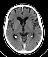
8 8 Image acquisition the slice X-ray beam is narrowed by an collimator Only one thin part of the body will be radiated

9 9 Image acquisition: the Voxel The slice will be partitioned mathematically into small Volume elements - voxel. The attenuation wiil be measured in the voxels as a constant value The image element in a plane is a Pixel
10 10 Concept of X-ray Attenuation SCATTERED X-RAYSX Incident X-ray BODY TISSUE Transmitted ray X-ray The degree beam passing of attenuation through is the measurable body is attenuated with CT and (loses is expressed its energy) in by: HU Absorption (Hounsfield) unit HU Scattering gives an indication of tissue density (CT Density)
11 11 Hounsfield Unit Scale Spleen Kidneys Blood Heart Liver Tumor 40 Bone Pancreas Adrenal Gland Intestine Bladder 0 Water Mamma Air Fat Lung Rule Rule of of thumb: The The CT CT value of of water is is 0 and and air air The The relative values of of the the other tissues are are calculated relative to to that that of of water This is the CT number or Hounsfield unit (HU)

12 12 Headline


13 13 CT then CT now.. SIRETOM 1974 Spirit 2004
14 14 CT Basics: Sequential scanning In 1970 s, CT worked only using a sequential scan One Scan - First rotation ( 2 seconds per rotation!! ) Rotation of tube and detector around Radiation exposure After each scan a table movement was performed The tube and detector system moved back to the initial position Because of cables! Table moves Second rotation ( 2 seconds per rotation!! ) Table moves etc etc Problem: Long examination time The lung could not be scanned in one breath hold
15 15 Conventional sequential CT... Sequence-Scan: - long cycle time I.S.D* I.S.D* Inter scan delay - time between 1st slice to 2nd slice -Gantry rotation, gantry stop, -patient moves, -gantry rotates, gantry stop etc. Please note that conventional sequential CT still used today for some head scans ( however, gantry does not require to return anticlockwise to start position due to slip rings )

16 16 CT Basics Lungs like a sponge! deep Inspiration shallow Inspiration Mis-registration due to different levels of respiration between slices
17 : The Spiral CT Era.

18 18 Conventional CT versus Spiral-CT... 2D-Slice 3D-Volume with I.S.D.* no I.S.D
 Continuous radiation Continuous volume acquisition Table")
19 19 Principles of Spiral CT Continuous gantry rotation Continuous table feed ( head or foot direction ) Continuous radiation Continuous volume acquisition Table movement
20 20 Principles of Spiral CT 30s - 40s Volume scanning in a single breath hold Raw data ( CT computer data) is created, then image (picture) data is processed using CT computer
21 21 Principles of Spiral CT Continuous Slices Concurrent Image Reconstruction during the spiral acquisition or Retrospective Image Reconstruction
22 22 Principles of Spiral CT Image Reconstruction at arbitrary slice position over a limited volume
23 23 Principles of Spiral CT Image Reconstruction with gaps larger distance (increment) between the slices than the slice thickness
24 24 Principles of Spiral CT Image Reconstruction with overlap smaller distance (increment) between the slices than the slice thickness
25 25 Principles of Spiral CT Problem: Partial Volume Artifact Partial Volume Artifact: Suspicious lesion is covered partially in one slice Overlapping axial slices Reduces Partial Volume Artifacts by centering the lesion within the slice No additional radiation dose
26 26 Spiral CT benefits Complete Volume coverage Faster data acquisition More patient comfort Data acquisition in one breath hold Less movement artifacts Less contrast media Less patient dose Higher patient throughput
27 27 New Concept with Single Slice Spiral Spiral Scanning can be done at variable speed relative to the collimation Pitch = Table Feed per Rotation Collimation Examples for Collimation = 5.0 mm Table feed per rotation = 5.0 mm Pitch 1.0 Table feed per rotation = 7.5 mm Pitch 1.5 Table feed per rotation = 10.0mm Pitch 2.0 Freely selectable from 1.0 to 2.0 [Emotion (single slice )]
28 28 Clinical Benefits of Increased Pitch More coverage in the same time 30s Pitch 1 30s Pitch 2
29 29 Pitch & Image Quality Pitch 1 Scan direction Pitch 2 Image plane Scan direction Data points are stretched with increasing Pitch causing slice profile broadening
30 30 Slice Profile (SP) Effective slice thickness of an image Slice Profile Resolution Factors influencing Slice Profile Collimation Pitch Interpolation algorithm (360 or 180 )
31 31 In the worst case scenario. Example 5 mm collimation, Pitch mm Slice Profile 5 mm collimation, Pitch mm Slice Profile Scanning at Pitch 2 leads to decrease in image quality on single slice CT & other vendors MSCT

32 32 Clinical Benefits of Increased Pitch Reduced scan time & dose for the same coverage assuming same slice size 30s 15s Pitch mm/rot Pitch mm/rot


33 33 Clinical Benefits of Subsecond Spiral 8mm 28s 22s with 0.8s rotation 10mm 30s 7mm 32s 0.75s SPIRAL 1s SPIRAL 30s with 1.0s rotation Reduced scan time & dose Improved resolution More coverage Improved Temporal Resolution Less motion artifacts New applications Cardiac CT 40cm 30cm 0.8s Spiral 1.0s Spiral
34 34 Chest Imaging Protocols Comparison Sequential CT Slice Imaging ~ 2s per slice ml contrast 8-10 mm collimation Single Spiral CT Volume Imaging 25s - 40s per volume ml contrast 3-5 mm collimation Eliminates respiratory mis-registration Faster with improved spatial resolution Reduced contrast dosage
35 Conventional vs. Single-Slice Spiral vs. Multi-Slice Spiral 35 Single Slice Single Volume Multi-slice Volume I.S.D* no I.S.D * Inter Scan Delay
36 36 Multi-Slice CT Scanning Multi-Slice CT Multiple slices are acquired for each rotation. With the currently available multi-slice scanners, either 2, 4*, 6, 10, 16, 24**, 40 or 64 slices can be acquired per rotation. Refurbished Volume Zoom / Sensation 4 ** Sensation Open


37 37 Multi-slice Detector Designs Single slice CT s have one detector row,while multi-slice CT s have multiple detector rows. Sensation 64 Emotion 6
38 38 Multi-Detector Adaptive Array Design Scan-FOV z-axis 3 2 2x1 8x.5 2x1 2 3 Emotion 6 adaptive array detector
39 39 Adaptive Array Design S16 Scan-FOV 4 x x.75 4 x 1.5 z-axis
40 40 Detector Configuration Sensation 16 4x1.5mm 16x0.75mm 4x1.5mm 16x0.75mm Detail Mode 16x1.5mm Routine Mode
41 41 Detector Configuration Sensation 64 4x1.2mm 32x0.6mm 4x1.2mm 64 x 0.6mm Routine Mode 24 x 1.2mm Volume Mode 28.8mm z-coverage
42 42 Slice Collimation & Width... For all Siemens MSCT s a combination of Collimated slice and reconstructed slice thickness have to be selected The slice width is the true width of a Siemens CT reconstructed slice ( unlike other vendor s MSCT systems who have slice broadening ) Slice width can only be thicker than slice collimation cannot be thinner The slice thickness can be changed retrospectively
43 43 Slice collimation... Single Slice CT. Slice collimation is the slice thickness collimated by the tube collimator determining the Z coverage per rotation. Multi Slice CT Slice collimation is the total slice thickness collimated by the tube collimator and then divided by the number of active detector channels.
44 44 Two different definitions for Pitch Pitch Factor : table movement per rotation divided by the total slice collimation Volume Pitch : table movement per rotation divided by the slice collimation e.g. Sensation 16 Abdomen scan Pitch Factor: 18mm per rotation 16 rows x 0.75 mm = Pitch 1,5 Volume Pitch Factor: 18mm per rotation 0.75 mm = Pitch 24

45 Pitch... In multi-slice spiral with the Emotion Duo / 6 and the Sensation, you select the slice collimation together with the slice width, and the slice width is not affected by the pitch or the algorithm. No slice Broadening What you ask for is what you get! 45
46 46 Clinical Applications of Spiral CT Routine Volume Acquisition (in a breath hold) Routine Neuro Spiral Imaging Multiphasic Spiral Contrast Studies CT Angiography's Musculoskeletal 3D Imaging
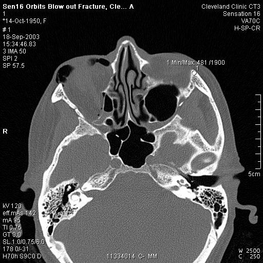
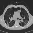
47 47 Routine Applications Bone and lungs Soft tissue

48 48 Bone & Lungs Black & White - High Contrast


49 Bone and lungs 49 Big differences in the tissue densities High contrast resolution is needed High images noise less dose is needed No differentiation of small tissue density differences Inner ear Lung

50 50 MTF: Catphan HC-insert with kernels H30s, U95u H30s, FOV = 200 mm, 7lp /cm U95u,FOV = 100 mm, 20lp /cm


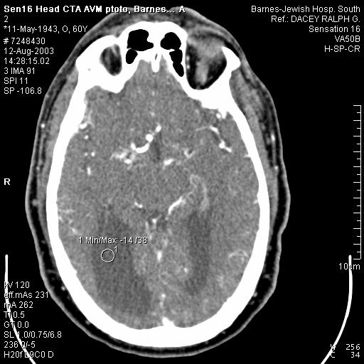
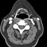
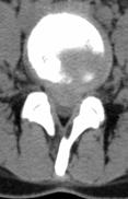
51 Soft Tissue - Low Contrast Resolution 51 Possibility to visualize different tissue densities, which are close together No image noise you need a higher dose Head Abdomen/Liver
52 52 Low Contrast Resolution To visualize small density differences, a good Low Contrast resolution is needed Specification of Low Contrast Resolution Phantom: CATPHAN (16mm) Object size: 3mm contrast diff.: 3HU Dose at the surface: 19.7 mgy at 100/104 mas Technic: 1.0 sec; 10mm, 120kv
 73 mas 225 mas 20 cm Catphan FOV = 250")
53 53 Low-contrast: Emotion (B30s,130 kv, 10 mm) 73 mas 225 mas 20 cm Catphan FOV = 250 mm


54 54 Routine Mix of CT Examination Only 10% are High Contrast Studies HC LC
55 55 3D Imaging - Abbreviations MPR Multi Planar Reconstructions Transaxial images are combined to volume. The volume can be reformatted to secondary images in selected planes ( sagittal, coronal or oblique) SSD Shaded Surface Display Surface images of tissue structure are created out of the volume dataset. A three dimensional object is calculated from voxels, whose threshold values are within a specific density range VRT Volume Rendering Technique Possibility to render different tissues, which have a different densities, as a 3D object in different colors and with different brightness and opacity MIP Maximum Intensity Projection Possibility to render different tissues, which have high density and show them as a 3D object in different grey scales
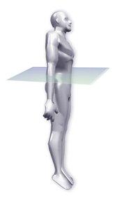
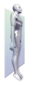
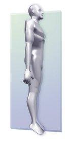
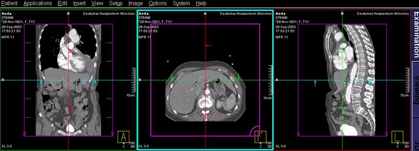
56 56 Reconstructions Orientations coronal axial sagittal


57 High-Resolution Ankle Study 57 Axial Imaging with Multiplanar Results Coronal Reformat Axial Image 1 mm, Pitch 2, Emotion Sagittal Reformat


58 3D Trauma Imaging Fractures 58 Spine (SSD) Spine (VRT) Spine (MPR)

59 Musculo-Skeletal 3D Imaging (VRT) 59 Osteosacroma Left Pelvis 2 mm, Pitch 1.5, Emotion

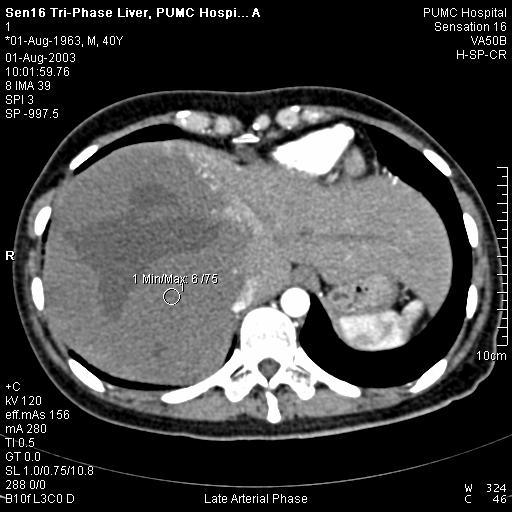
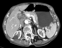
60 Why use an injector with contrast media for an examination? 60 Images with contrast media injection helps by the diagnosis and by the differential diagnosis No injection With injection Multiphase Liver examination
61 61 Liver Study with Contrast Medium ArterialPhase VenousPhase Arterial Venous
 62 1 2 1")

62 4-phase Liver Hemangioma (Emotion) Pre-contrast 2 Arterial 3 Portal-venous 4 Delayed phase 3 4
 CT")

63 Contrast media injection for CT Angio s 63 Angio study of Kidney (MIP) CT Angiography Visualization of vessels without catheter Leg femoral runoff (MIP)
64 64 Advanced Contrast Studies VRT ( InSpace )


65 Neuro CTA Carotid Arteries 65 2 mm, Pitch 2, Emotion MIP 2 x 1mm, Emotion Duo VRT

66 Abdominal CT Angiography Aortic Stent 66 2 x 1mm, Emotion Duo VRT

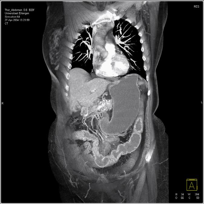
67 67 Headline SOMATOM Sensation 64 VRT( InSpace) 6 sec for 350 mm 64 x 0.6mm (2x32) Resolution 0.4 mm Rotation 0.37 sec 120 kv / 150 mas Courtesy of University of Erlangen, Department of Radiology and Institute of Medical Physics

68 68 Headline SOMATOM Sensation 64 MIP 6 sec for 350 mm 64 x 0.6mm (2x32) Resolution 0.4 mm Rotation 0.37 sec 120 kv / 150 mas Courtesy of University of Erlangen, Department of Radiology and Institute of Medical Physics


69 69 Headline Heart Specimen Study SOMATOM Sensation 64 3mm VRT Stent 3 mm Slice thick. 0.6 mm Resolution 0.4 mm 3mm Excellent visualization of 3 mm stent Significant reduction of stent struts blooming artifacts
 33 sec for 1570 mm")


70 70 Headline SOMATOM Sensation 64 VRT(InSpace) 33 sec for 1570 mm 64 x 0.6mm (2x32) Resolution 0.4 mm Rotation 0.5sec 120 kv / 148mAs Courtesy of University of Erlangen and University of Tübingen

71 71 Headline SOMATOM Sensation 64 VRT 33 sec for 1570 mm 64 x 0.6mm (2x32) Resolution 0.4 mm Rotation 0.5sec 120 kv / 148mAs Courtesy of University of Erlangen and University of Tübingen
72 72 Real-time Color VRT with InSpace 4D Emotion 6 Blocked Venous Stent Courtesy Klinikum Nord,Nürnberg,Germany

73 Real-time Color VRT with InSpace 4D 73
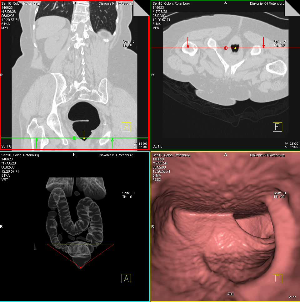
74 74 Syngo Colonography
Computer-Tomography II: Image reconstruction and applications
 Computer-Tomography II: Image reconstruction and applications Prof. Dr. U. Oelfke DKFZ Heidelberg Department of Medical Physics (E040) Im Neuenheimer Feld 280 69120 Heidelberg, Germany u.oelfke@dkfz.de
Corso di laurea in Fisica A.A Fisica Medica 4 TC
 Corso di laurea in Fisica A.A. 2007-2008 Fisica Medica 4 TC Computed Tomography Principles 1. Projection measurement 2. Scanner systems 3. Scanning modes Basic Tomographic Principle The internal structure
Shadow casting. What is the problem? Cone Beam Computed Tomography THE OBJECTIVES OF DIAGNOSTIC IMAGING IDEAL DIAGNOSTIC IMAGING STUDY LIMITATIONS
 Cone Beam Computed Tomography THE OBJECTIVES OF DIAGNOSTIC IMAGING Reveal pathology Reveal the anatomic truth Steven R. Singer, DDS srs2@columbia.edu IDEAL DIAGNOSTIC IMAGING STUDY Provides desired diagnostic
Spiral CT. Protocol Optimization & Quality Assurance. Ge Wang, Ph.D. Department of Radiology University of Iowa Iowa City, Iowa 52242, USA
 Spiral CT Protocol Optimization & Quality Assurance Ge Wang, Ph.D. Department of Radiology University of Iowa Iowa City, Iowa 52242, USA Spiral CT Protocol Optimization & Quality Assurance Protocol optimization
Ch. 4 Physical Principles of CT
 Ch. 4 Physical Principles of CT CLRS 408: Intro to CT Department of Radiation Sciences Review: Why CT? Solution for radiography/tomography limitations Superimposition of structures Distinguishing between
Computer-Tomography I: Principles, History, Technology
 Computer-Tomography I: Principles, History, Technology Prof. Dr. U. Oelfke DKFZ Heidelberg Department of Medical Physics (E040) Im Neuenheimer Feld 280 69120 Heidelberg, Germany u.oelfke@dkfz.de History
Medical Image Processing: Image Reconstruction and 3D Renderings
 Medical Image Processing: Image Reconstruction and 3D Renderings 김보형 서울대학교컴퓨터공학부 Computer Graphics and Image Processing Lab. 2011. 3. 23 1 Computer Graphics & Image Processing Computer Graphics : Create,
Image Acquisition Systems
 Image Acquisition Systems Goals and Terminology Conventional Radiography Axial Tomography Computer Axial Tomography (CAT) Magnetic Resonance Imaging (MRI) PET, SPECT Ultrasound Microscopy Imaging ITCS
Radiology. Marta Anguiano Millán. Departamento de Física Atómica, Molecular y Nuclear Facultad de Ciencias. Universidad de Granada
 Departamento de Física Atómica, Molecular y Nuclear Facultad de Ciencias. Universidad de Granada Overview Introduction Overview Introduction Tecniques of imaging in Overview Introduction Tecniques of imaging
A closer look at CT scanning
 Vet Times The website for the veterinary profession https://www.vettimes.co.uk A closer look at CT scanning Author : Charissa Lee, Natalie Webster Categories : General, Vets Date : April 3, 2017 A basic
Fundamentals of CT imaging
 SECTION 1 Fundamentals of CT imaging I History In the early 1970s Sir Godfrey Hounsfield s research produced the first clinically useful CT scans. Original scanners took approximately 6 minutes to perform
BME I5000: Biomedical Imaging
 1 Lucas Parra, CCNY BME I5000: Biomedical Imaging Lecture 4 Computed Tomography Lucas C. Parra, parra@ccny.cuny.edu some slides inspired by lecture notes of Andreas H. Hilscher at Columbia University.
Digital Image Processing
 Digital Image Processing SPECIAL TOPICS CT IMAGES Hamid R. Rabiee Fall 2015 What is an image? 2 Are images only about visual concepts? We ve already seen that there are other kinds of image. In this lecture
3/27/2012 WHY SPECT / CT? SPECT / CT Basic Principles. Advantages of SPECT. Advantages of CT. Dr John C. Dickson, Principal Physicist UCLH
 3/27/212 Advantages of SPECT SPECT / CT Basic Principles Dr John C. Dickson, Principal Physicist UCLH Institute of Nuclear Medicine, University College London Hospitals and University College London john.dickson@uclh.nhs.uk
RADIOLOGY AND DIAGNOSTIC IMAGING
 Day 2 part 2 RADIOLOGY AND DIAGNOSTIC IMAGING Dr hab. Zbigniew Serafin, MD, PhD serafin@cm.umk.pl 2 3 4 5 CT technique CT technique 6 CT system Kanal K: RSNA/AAPM web module: CT Systems & CT Image Quality
Computed tomography - outline
 Computed tomography - outline Computed Tomography Systems Jørgen Arendt Jensen and Mikael Jensen (DTU Nutech) October 6, 216 Center for Fast Ultrasound Imaging, Build 349 Department of Electrical Engineering
MEDICAL IMAGING 2nd Part Computed Tomography
 MEDICAL IMAGING 2nd Part Computed Tomography Introduction 2 In the last 30 years X-ray Computed Tomography development produced a great change in the role of diagnostic imaging in medicine. In convetional
Tomographic Reconstruction
 Tomographic Reconstruction 3D Image Processing Torsten Möller Reading Gonzales + Woods, Chapter 5.11 2 Overview Physics History Reconstruction basic idea Radon transform Fourier-Slice theorem (Parallel-beam)
Optimisation of Toshiba Aquilion ONE Volume Imaging
 Optimisation of Toshiba Aquilion ONE Volume Imaging Jane Edwards, RPRSG Royal Free London NHS Foundation Trust Dr Mufudzi Maviki, Plymouth Hospitals NHS Trust Background In 2011/12 Radiology at RFH was
The Near Future in Cardiac CT Image Reconstruction
 SCCT 2010 The Near Future in Cardiac CT Image Reconstruction Marc Kachelrieß Institute of Medical Physics (IMP) Friedrich-Alexander Alexander-University Erlangen-Nürnberg rnberg www.imp.uni-erlangen.de
MEDICAL EQUIPMENT: COMPUTED TOMOGRAPHY. Prof. Yasser Mostafa Kadah
 MEDICAL EQUIPMENT: COMPUTED TOMOGRAPHY Prof. Yasser Mostafa Kadah www.k-space.org Recommended Textbook X-Ray Computed Tomography in Biomedical Engineering, by Robert Cierniak, Springer, 211 Computed Tomography
Some reference material
 Some reference material Physics reference book on medical imaging: A good one is The Essential Physics of Medical Imaging, 3 rd Ed. by Bushberg et al. ($170! new). However, there are several similar books
Multi-slice CT Image Reconstruction Jiang Hsieh, Ph.D.
 Multi-slice CT Image Reconstruction Jiang Hsieh, Ph.D. Applied Science Laboratory, GE Healthcare Technologies 1 Image Generation Reconstruction of images from projections. textbook reconstruction advanced
Cardiac Dual Energy CT: Technique
 RSNA 2013, VSCA51-01, Chicago, Dec. 5, 2013 Cardiac Radiology Series Cardiac Dual Energy CT: Technique Willi A. Kalender, Ph.D. Institute of Medical Physics University of Erlangen www.imp.uni-erlangen.de
CT NOISE POWER SPECTRUM FOR FILTERED BACKPROJECTION AND ITERATIVE RECONSTRUCTION
 CT NOISE POWER SPECTRUM FOR FILTERED BACKPROJECTION AND ITERATIVE RECONSTRUCTION Frank Dong, PhD, DABR Diagnostic Physicist, Imaging Institute Cleveland Clinic Foundation and Associate Professor of Radiology
FINDING THE TRUE EDGE IN CTA
 FINDING THE TRUE EDGE IN CTA by: John A. Rumberger, PhD, MD, FACC Your patient has chest pain. The Cardiac CT Angiography shows plaque in the LAD. You adjust the viewing window trying to evaluate the stenosis
Computed Tomography. Principles, Design, Artifacts, and Recent Advances. Jiang Hsieh THIRD EDITION. SPIE PRESS Bellingham, Washington USA
 Computed Tomography Principles, Design, Artifacts, and Recent Advances THIRD EDITION Jiang Hsieh SPIE PRESS Bellingham, Washington USA Table of Contents Preface Nomenclature and Abbreviations xi xv 1 Introduction
CT: Physics Principles & Equipment Design
 CT: Physics Principles & Equipment Design James Kofler, Ph.D Radiology Mayo Clinic Rochester, MN June 27, 2012 Disclosures Nothing to disclose Learning Objectives Understand fundamental concepts of - CT
Enhancement Image Quality of CT Using Single Slice Spiral Technique
 Enhancement Image Quality of CT Using Single Slice Spiral Technique Doaa. N. Al Sheack 1 and Dr.Mohammed H. Ali Al Hayani 2 1 2 Electronic and Communications Engineering Department College of Engineering,
MEDICAL IMAGING 2nd Part Computed Tomography
 MEDICAL IMAGING 2nd Part Computed Tomography Introduction 2 In the last 30 years X-ray Computed Tomography development produced a great change in the role of diagnostic imaging in medicine. In convetional
CLASS HOURS: 4 CREDIT HOURS: 4 LABORATORY HOURS: 0
 Revised 10/10 COURSE SYLLABUS TM 220 COMPUTED TOMOGRAPHY PHYSICS CLASS HOURS: 4 CREDIT HOURS: 4 LABORATORY HOURS: 0 CATALOG COURSE DESCRIPTION: This course is one of a three course set in whole body Computed
Computed Tomography. Principles of Medical Imaging. Contents. Prof. Dr. Philippe Cattin. MIAC, University of Basel. Sep 26th/Oct 3rd, 2016
 Computed Tomography Principles of Medical Imaging Prof. Dr. Philippe Cattin MIAC, University of Basel Contents Abstract 1 Computed Tomography Basics Introduction Computed Tomography Hounsfield's CT Prototype
Philips SPECT/CT Systems
 Philips SPECT/CT Systems Ling Shao, PhD Director, Imaging Physics & System Analysis Nuclear Medicine, Philips Healthcare June 14, 2008 *Presented SNM08 Categorical Seminar - Quantitative SPECT and PET
Optimization of CT Simulation Imaging. Ingrid Reiser Dept. of Radiology The University of Chicago
 Optimization of CT Simulation Imaging Ingrid Reiser Dept. of Radiology The University of Chicago Optimization of CT imaging Goal: Achieve image quality that allows to perform the task at hand (diagnostic
Introduction to Biomedical Imaging
 Alejandro Frangi, PhD Computational Imaging Lab Department of Information & Communication Technology Pompeu Fabra University www.cilab.upf.edu X-ray Projection Imaging Computed Tomography Digital X-ray
PURE. ViSION Edition PET/CT. Patient Comfort Put First.
 PURE ViSION Edition PET/CT Patient Comfort Put First. 2 System features that put patient comfort and safety first. Oncology patients deserve the highest levels of safety and comfort during scans. Our Celesteion
Equipment Specification
 MULTISLICE CT SCANNER ( 16 Slices ) Merk : Hitachi Japan Model : SUPRIA 5 MHU Price : Rp 6.512.360.215,27 No Equipment Specification 1 2 3 Scanner Gantry Object for scanning : Whole body including head
CT Basics: Image Processing and Reconstruction Module 4
 Module 4 For educational and institutional use. This transcript is licensed for noncommercial, educational inhouse or online educational course use only in educational and corporate institutions. Any broadcast,
The protocols used to scan the musculoskeletal system are tailored to each patient and
 Chapter 22. Musculoskeletal Protocols The protocols used to scan the musculoskeletal system are tailored to each patient and region being examined. The clinical indication for the examination will also
CT vs. VolumeScope: image quality and dose comparison
 CT vs. VolumeScope: image quality and dose comparison V.N. Vasiliev *a, A.F. Gamaliy **b, M.Yu. Zaytsev b, K.V. Zaytseva ***b a Russian Sci. Center of Roentgenology & Radiology, 86, Profsoyuznaya, Moscow,
First CT Scanner. How it Works. Contemporary CT. Before and After CT. Computer Tomography: How It Works. Medical Imaging and Pattern Recognition
 Computer Tomography: How t Works Medical maging and Pattern Recognition Lecture 7 Computed Tomography Oleh Tretiak Only one plane is illuminated. Source-subject motion provides added information. 2 How
Whole Body Submillimeter Scan
 128 Whole Body Submillimeter Scan The real value of 64ch/128slice CT systems does not come from the ability to perfom cardiac scans but the capability to scan all parts of the body in high definition submillimeter
Diagnostic imaging techniques. Krasznai Zoltán. University of Debrecen Medical and Health Science Centre Department of Biophysics and Cell Biology
 Diagnostic imaging techniques Krasznai Zoltán University of Debrecen Medical and Health Science Centre Department of Biophysics and Cell Biology 1. Computer tomography (CT) 2. Gamma camera 3. Single Photon
Hitachi Medical Systems America, Inc. Hitachi Medical Corporation
 Advanced 128 Advanced 128 128 Slice Capability Enlarged 75cm Aperture Thin Gantry Profile 88cm Intelli IP Advanced, Iterative Reconstruction IntelliCenter Auto-Lateral Shifting Table, up to 16cm Range
Computational Medical Imaging Analysis Chapter 4: Image Visualization
 Computational Medical Imaging Analysis Chapter 4: Image Visualization Jun Zhang Laboratory for Computational Medical Imaging & Data Analysis Department of Computer Science University of Kentucky Lexington,
Image Quality Assessment and Quality Assurance of Advanced Imaging Systems for IGRT. AAPM Penn-Ohio Chapter Sep 25, 2015 Soyoung Lee, PhD
 Image Quality Assessment and Quality Assurance of Advanced Imaging Systems for IGRT AAPM Penn-Ohio Chapter Sep 25, 2015 Soyoung Lee, PhD 1 Outline q Introduction q Imaging performances in 4D-CBCT Image
AAPM Standard of Practice: CT Protocol Review Physicist
 AAPM Standard of Practice: CT Protocol Review Physicist Dianna Cody, Ph.D., DABR, FAAPM U.T.M.D. Anderson Cancer Center September 11, 2014 2014 Texas Radiation Regulatory Conference Goals Understand purpose
ImPACT. Information Leaflet No. 1: CT Scanner Acceptance Testing
 ImPACT Information Leaflet No. 1: CT Scanner Acceptance Testing Version 1.02, 18/05/01 CONTENTS: 1. SCOPE OF LEAFLET 2. GENERAL PRINCIPLES OF ACCEPTANCE AND COMMISSIONING 2.1 PHANTOMS 2.2 EXPOSURE AND
Annexure XII SPECIFICATIONS FOR A NEW STATE OF ART 16 SLICE ALL PURPOSE C. T. SCANNER
 Annexure XII SPECIFICATIONS FOR A NEW STATE OF ART 16 SLICE ALL PURPOSE C. T. SCANNER A) Scanner Design X-Ray generator and tube: 1. Scanner: Whole body spiral CT scanner (16 slices) of latest technology.
Lower Dose with Confidence
 Lower Dose with Confidence The Next Generation SCENARIA CT is Here. 64 or 128 Slice Capability The SCENARIA SE delivers lower dose technologies*, enhanced patient access, fast workflow speed and added
Clinical Importance. Aortic Stenosis. Aortic Regurgitation. Ultrasound vs. MRI. Carotid Artery Stenosis
 Clinical Importance Rapid cardiovascular flow quantitation using sliceselective Fourier velocity encoding with spiral readouts Valve disease affects 10% of patients with heart disease in the U.S. Most
Technical aspects of SPECT and SPECT-CT. John Buscombe
 Technical aspects of SPECT and SPECT-CT John Buscombe What does the clinician need to know? For SPECT What factors affect SPECT How those factors should be sought Looking for artefacts For SPECT-CT Issues
Medical Imaging Projects
 NSF REU MedIX Summer 2006 Medical Imaging Projects Daniela Stan Raicu, PhD http://facweb.cs.depaul.edu/research draicu@cs.depaul.edu Outline Medical Informatics Imaging Modalities Computed Tomography Medical
Fits you like no other
 Fits you like no other BrightView X and XCT specifications The new BrightView X system is a fully featured variableangle camera that is field-upgradeable to BrightView XCT without any increase in room
Motion Compensation from Short-Scan Data in Cardiac CT
 Motion Compensation from Short-Scan Data in Cardiac CT Juliane Hahn 1,2, Thomas Allmendinger 1, Herbert Bruder 1, and Marc Kachelrieß 2 1 Siemens Healthcare GmbH, Forchheim, Germany 2 German Cancer Research
Brilliance CT Big Bore.
 1 2 2 There are two methods of RCCT acquisition in widespread clinical use: cine axial and helical. In RCCT with cine axial acquisition, repeat CT images are taken each couch position while recording respiration.
8/2/2016. Measures the degradation/distortion of the acquired image (relative to an ideal image) using a quantitative figure-of-merit
 using a quantitative figure-of-merit") Ke Li Assistant Professor Department of Medical Physics and Department of Radiology School of Medicine and Public Health, University of Wisconsin-Madison This work is partially supported by an NIH Grant
Ke Li Assistant Professor Department of Medical Physics and Department of Radiology School of Medicine and Public Health, University of Wisconsin-Madison This work is partially supported by an NIH Grant
Diagnostic quality of time-averaged ECG-gated CT data
 Diagnostic quality of time-averaged ECG-gated CT data Almar Klein a, Luuk J. Oostveen b, Marcel J.W. Greuter c, Yvonne Hoogeveen b, Leo J. Schultze Kool b, Cornelis H. Slump a and W. Klaas Jan Renema b
Solid Capabilities Are Built Into the Supria Plus. Putting You On The Path of High Quality, Cost-Effective CT Scanning
 Specification Data Putting You On The Path of High Quality, Cost-Effective CT Scanning Solid Capabilities Are Built Into the Supria Plus Addressing the challenges of controlling healthcare organization
Chapter 4. Image Reconstruction and Review. Image Reconstruction
 Chapter 4 Image Reconstruction and Review Data acquisition with MDCT scanners is relatively straightforward. Scanners offer a fixed number of slice thickness options, and other variables are controlled
ML reconstruction for CT
 ML reconstruction for CT derivation of MLTR rigid motion correction resolution modeling polychromatic ML model dual energy ML model Bruno De Man, Katrien Van Slambrouck, Maarten Depypere, Frederik Maes,
INTRODUCTION TO MEDICAL IMAGING- 3D LOCALIZATION LAB MANUAL 1. Modifications for P551 Fall 2013 Medical Physics Laboratory
 INTRODUCTION TO MEDICAL IMAGING- 3D LOCALIZATION LAB MANUAL 1 Modifications for P551 Fall 2013 Medical Physics Laboratory Introduction Following the introductory lab 0, this lab exercise the student through
Computational Medical Imaging Analysis
 Computational Medical Imaging Analysis Chapter 2: Image Acquisition Systems Jun Zhang Laboratory for Computational Medical Imaging & Data Analysis Department of Computer Science University of Kentucky
DUE to beam polychromacity in CT and the energy dependence
 1 Empirical Water Precorrection for Cone-Beam Computed Tomography Katia Sourbelle, Marc Kachelrieß, Member, IEEE, and Willi A. Kalender Abstract We propose an algorithm to correct for the cupping artifact
Experience Boundless Performance
 Experience Boundless Performance About Samsung Samsung Electronics Co., Ltd. inspires the world and shapes the future with transformative ideas and technologies, redefining the worlds of TVs, smartphones,
8/7/2017. Disclosures. MECT Systems Overview and Quantitative Opportunities. Overview. Computed Tomography (CT) CT Numbers. Polyenergetic Acquisition
 CT Numbers. Polyenergetic Acquisition") Quantitative Multi-Energy Computed Tomography: Imaging and Therapy Advancements Disclosures MECT Systems Overview and Quantitative Opportunities The speaker receives research funding from GE Healthcare
Quantitative Multi-Energy Computed Tomography: Imaging and Therapy Advancements Disclosures MECT Systems Overview and Quantitative Opportunities The speaker receives research funding from GE Healthcare
Micro-CT Methodology Hasan Alsaid, PhD
 Micro-CT Methodology Hasan Alsaid, PhD Preclinical & Translational Imaging LAS, PTS, GlaxoSmithKline 20 April 2015 Provide basic understanding of technical aspects of the micro-ct Statement: All procedures
Fits you like no other
 Fits you like no other Philips BrightView X and XCT specifications The new BrightView X system is a fully featured variableangle camera that is field-upgradeable to BrightView XCT without any increase
QIBA PET Amyloid BC March 11, Agenda
 QIBA PET Amyloid BC March 11, 2016 - Agenda 1. QIBA Round 6 Funding a. Deadlines b. What projects can be funded, what cannot c. Discussion of projects Mechanical phantom and DRO Paul & John? Any Profile
Physical bases of X-ray diagnostics
 Physical bases of X-ray diagnostics Dr. István Voszka Possibilities of X-ray production (X-ray is produced, when charged particles of high velocity are stopped) X-ray tube: Relatively low accelerating
Deviceless respiratory motion correction in PET imaging exploring the potential of novel data driven strategies
 g Deviceless respiratory motion correction in PET imaging exploring the potential of novel data driven strategies Presented by Adam Kesner, Ph.D., DABR Assistant Professor, Division of Radiological Sciences,
As fl exible as your care requires
 As fl exible as your care requires Philips Ingenuity Flex 32 CT Built on Ingenuity The Philips Ingenuity Flex 32 helps you provide excellent care with outstanding flexibility, now and in the future. Built
Symbia T Series System Specifications Answers for life.
 www.siemens.com/mi System Specifications Answers for life. 2 Diagnostic Excellence Today s healthcare institutions have increasingly diverse patient needs, greater budget limitations and the need for higher
MDCT and 3D Workstations
 MDCT and 3D Workstations Scott A. Lipson, MD Associate Director of Imaging, Long Beach Memorial Medical Center, Long Beach, California MDCT and 3D Workstations A Practical How-To Guide and Teaching File
LAB DEMONSTRATION COMPUTED TOMOGRAPHY USING DESKCAT Lab Manual: 0
 LAB DEMONSTRATION COMPUTED TOMOGRAPHY USING DESKCAT Lab Manual: 0 Introduction This lab demonstration explores the physics and technology of Computed Tomography (CT) and guides the student and instructor
Biomedical Imaging. Computed Tomography. Patrícia Figueiredo IST
 Biomedical Imaging Computed Tomography Patrícia Figueiredo IST 2013-2014 Overview Basic principles X ray attenuation projection Slice selection and line projections Projection reconstruction Instrumentation
CT Protocol Review: Practical Tips for the Imaging Physicist Physicist
 CT Protocol Review: Practical Tips for the Imaging Physicist Physicist Dianna Cody, Ph.D., DABR, FAAPM U.T.M.D. Anderson Cancer Center August 8, 2013 AAPM Annual Meeting Goals Understand purpose and importance
MR Advance Techniques. Vascular Imaging. Class III
 MR Advance Techniques Vascular Imaging Class III 1 Vascular Imaging There are several methods that can be used to evaluate the cardiovascular systems with the use of MRI. MRI will aloud to evaluate morphology
Introduction to Medical Imaging. Lecture 6: X-Ray Computed Tomography. CT number (in HU) = Overview. Klaus Mueller
 = Overview. Klaus Mueller") Overview Introduction to Medical Imaging Lecture 6: X-Ray Computed Tomography Scanning: rotate source-detector pair around the patient Klaus Mueller data Computer Science Department Stony Brook University
Overview Introduction to Medical Imaging Lecture 6: X-Ray Computed Tomography Scanning: rotate source-detector pair around the patient Klaus Mueller data Computer Science Department Stony Brook University
Computational Medical Imaging Analysis
 Computational Medical Imaging Analysis Chapter 1: Introduction to Imaging Science Jun Zhang Laboratory for Computational Medical Imaging & Data Analysis Department of Computer Science University of Kentucky
Modifications for P551 Fall 2014
 LAB DEMONSTRATION COMPUTED TOMOGRAPHY USING DESKCAT 1 Modifications for P551 Fall 2014 Introduction This lab demonstration explores the physics and technology of Computed Tomography (CT) and guides the
Image Post-Processing, Workflow, & Interpretation
 Image Post-Processing, Workflow, & Interpretation Richard L. Hallett, MD Chief, Cardiovascular Imaging Northwest Radiology Network Indianapolis, IN Adjunct Assistant Professor Stanford University Stanford,
Effect of Scattering on the Image. Reducing Compton Scatter with a Grid
 Effect of Scattering on the Image Increasing Compton scattering degrades image. Webb 21 Reducing Compton Scatter with a Grid Grids Parallel (focused at infinity) Linear Focused (see figure) Moving grids
CTA HEAD Perfusion AqONE without and with IV Contrast
 CTA HEAD Perfusion AqONE without and with IV Contrast Patient Position Adult Contrast Adult Injection Rate Supine IOML perpendicular to table top. IV: 100 ml with helical head CTA 50 ml without helical
SCENARIA 64-Slice CT Putting Advanced CT Within Reach.
 SCENARIA 64-Slice CT Putting Advanced CT Within Reach. Advancing the technology of Computed Tomography for over 30 years, Hitachi is a recognized innovator of lower dose*, high diagnostic value CT solutions.
US 1.
 US 1 Sample image: Normal pancreas seen on sonogram. Looking up from abdomen toward the head of the patient. The liver is in front of the pancreas. A vein draining the spleen is behind the pancreas http://www.radiologyinfo.org/photocat/photos.cfm?image=abdo-us-pancr.jpg&&subcategory=abdomen&&stop=9
Carotid Lumen Segmentation and Stenosis Grading Challenge
 Carotid Lumen Segmentation and Stenosis Grading Challenge Reinhard Hameeteman Maria Zuluaga Leo Joskowicz Moti Freiman Theo van Walsum version 1.00 may 07, 2009 This document contains a description of
Motion artifact detection in four-dimensional computed tomography images
 Motion artifact detection in four-dimensional computed tomography images G Bouilhol 1,, M Ayadi, R Pinho, S Rit 1, and D Sarrut 1, 1 University of Lyon, CREATIS; CNRS UMR 5; Inserm U144; INSA-Lyon; University
Agenda : Lung Density Breakout Session
 Agenda : Lung Density Breakout Session 1. : Mathew Fuld and Bernice Hoppel 2. Automatic Exposure Control (AEC) Evaluation : Sean Fain Round 4 Project 3. Dose reduction effects on emphysema metrics : Philip
Design and performance characteristics of a Cone Beam CT system for Leksell Gamma Knife Icon
 Design and performance characteristics of a Cone Beam CT system for Leksell Gamma Knife Icon WHITE PAPER Introduction Introducing an image guidance system based on Cone Beam CT (CBCT) and a mask immobilization
PRODUCT DATA. Advanced 128
 PRODUCT DATA Advanced 128 Supria 16 Slice CT Puts You On The Path of High Quality, Cost-Effective CT Scanning Solid Capabilities Are Built Into the Supria Addressing the challenges of controlling healthcare
Medical Imaging and Beyond
 Medical Imaging and Beyond Jesus J. Caban Schedule! Today:! Lecture: Medical Imaging and Beyond! Wednesday:! No Class (Thanksgiving Eve)! Final presentations:! Nov 29 th : W. Griffin, F. Zafar! Dec 1 st
Superior Imaging on the Go
 Superior Imaging on the Go About Samsung Samsung Electronics Co., Ltd. is a global leader in technology, opening new possibilities for people everywhere. Through relentless innovation and discovery, we
X-ray Computed Tomography: Principle and Recent Advancements
 X-ray Computed Tomography: Principle and Recent Advancements Jiang Hsieh, Ph.D. GE Medical Systems, Milwaukee, WI Jiang Hsieh SPIE MI 2003 Course Note 1 Principle and Recent Advancements in X-ray Computed
VieW 3D. 3D Post-Processing WorKstation THE THIRD DIMENSION. Version 3.1
 VieW 3D 3D Post-Processing WorKstation THE THIRD DIMENSION Version 3.1 iq-view 3D THE FULLY-FEATURED 3D MEDICAL IMAGING SOLUTION FOR RADIOLOGISTS iq-view 3D contains all components of iq-view with the
Patient Set-ups and Tumor Localizations
 Patient Set-ups and Tumor Localizations Amy S. Harrison Patient Positioning Prior to starting any localization or simulation procedure patients need to be positioned and immobilized Patients disease location
Automated Image Analysis Software for Quality Assurance of a Radiotherapy CT Simulator
 Automated Image Analysis Software for Quality Assurance of a Radiotherapy CT Simulator Andrew J Reilly Imaging Physicist Oncology Physics Edinburgh Cancer Centre Western General Hospital EDINBURGH EH4
AIDR 3D Iterative Reconstruction:
 Iterative Reconstruction: Integrated, Automated and Adaptive Dose Reduction Erin Angel, PhD Manager, Clinical Sciences, CT Canon Medical Systems USA Iterative Reconstruction 1 Since the introduction of
Medical Image Analysis, Assignment 3
 Centre for Mathematical Sciences, Mathematics, LTH, December 2014 Medical Image Analysis, Assignment 3 1 Introduction The purpose of this assignment is to give hands-on experience with handling DICOM images
Respiratory Motion Estimation using a 3D Diaphragm Model
 Respiratory Motion Estimation using a 3D Diaphragm Model Marco Bögel 1,2, Christian Riess 1,2, Andreas Maier 1, Joachim Hornegger 1, Rebecca Fahrig 2 1 Pattern Recognition Lab, FAU Erlangen-Nürnberg 2