Mounting and Operating Instructions EB EN ( ) Series 3730 Type Electropneumatic Positioner. Translation of original instructions
|
|
|
- Lisa Freeman
- 6 years ago
- Views:
Transcription

 Firmware version 2.")
1 Series 3730 Type Electropneumatic Positioner Old design Translation of original instructions New design Mounting and Operating Instructions EB EN ( ) Firmware version 2.22 Edition February 2018

2 Note on these mounting and operating instructions These mounting and operating instructions assist you in mounting and operating the device safely. The instructions are binding for handling SAMSON devices. ÎÎ For the safe and proper use of these instructions, read them carefully and keep them for later reference. ÎÎ If you have any questions about these instructions, contact SAMSON s After-sales Service Department (aftersalesservice@samson.de). The mounting and operating instructions for the devices are included in the scope of delivery. The latest documentation is available on our website at > Service & Support > Downloads > Documentation. Definition of signal words! DANGER Hazardous situations which, if not avoided, will result in death or serious injury! WARNING Hazardous situations which, if not avoided, could result in death or serious injury! NOTICE Property damage message or malfunction Note Additional information Tip Recommended action 2 EB EN
3 Contents 1 Important safety instructions Article code Design and principle of operation Technical data Attachment to the control valve Mounting parts and accessories Direct attachment Type Actuator Type 3277 Actuator Attachment according to IEC Attachment according to VDI/VDE Attachment to Type 3510 Micro-flow Valve Attachment to rotary actuators Heavy-duty version Reversing amplifier for double-acting actuators Reversing amplifier ( or ) Attaching positioners with stainless steel housings Air purging function for single-acting actuators Required mounting parts and accessories Connections Pneumatic connections Signal pressure gauges Supply pressure Signal pressure (output) Electrical connections Switching amplifier Operation Operating controls Volume restriction Q Start-up Adjusting the volume restriction Q Adapting the display direction Entering fail-safe action...48 EB EN 3
4 Contents 7.4 Setting other parameters Initialization Faults Zero calibration Reset Manual mode Code list Maintenance Servicing explosion-protected devices Dimensions in mm Fixing levels according to VDI/VDE 3845 (September 2010)...63 Test certificates EB EN
5 Firmware revisions 2.02 (old) 2.10 (new) New Reset function in Code P0, refer to section 7.8 New Manual mode function in Code P14, refer to section (old) 2.11 (new) Internal revisions 2.11 (old) 2.12 (new) Internal revisions 2.12 (old) 2.20 (new) Parameter change: Nominal range (P4) New assignment of parameter codes: Manual mode (P17) and Reset (P18) New parameter codes: Firmware version (P20) and Control mode (to include integral-action component, P21). See code list on page 54 onwards. New assignment of error codes E8 to E15. See error codes on page 57 onwards (old) 2.21 (new) 2.21 (old) 2.22 (new) Optimized detection of zero and initialization routine Limit value A1 (P12) and Limit value A2 (P13): extended setting range to 0 to 100 % (same behavior as for firmware 2.20). See code list on page 54. Nominal range (P4): extended setting ranges. See code list on page 55. EB EN 5
6 Important safety instructions 1 Important safety instructions For your own safety, follow these instructions concerning the mounting, start up and operation of the positioner: The device is to be mounted, started up or operated only by trained and experienced personnel familiar with the product. According to these mounting and operating instructions, trained personnel is referred to as individuals who are able to judge the work they are assigned to and recognize possible dangers due to their specialized training, their knowledge and experience as well as their knowledge of the applicable standards. Explosion-protected versions of this device are to be operated only by personnel who has undergone special training or instructions or who is authorized to work on explosion-protected devices in hazardous areas. Refer to section 10. Any hazards that could be caused in the valve by the process medium, the signal pressure or by moving parts are to be prevented by taking appropriate precautions. If inadmissible motions or forces are produced in the pneumatic actuator as a result of the supply pressure level, it must be restricted using a suitable supply pressure reducing station. To avoid damage to any equipment, the following also applies: Do not operate the positioner with the back of the positioner/vent opening facing upwards. The vent opening must not be sealed or restricted when the positioner is installed on site. Vent opening Proper shipping and storage are assumed. Do not ground electric welding equipment near to the positioner. Note Devices with a CE marking fulfill the requirements of the Directives 2014/30/EU and 2011/65/EU and, depending on the version, 2014/34/EU as well. The declarations of conformity are included at the end of these instructions. 6 EB EN
7 Article code 2 Article code Positioner Type x x x 0 0 x With LCD and autotune, set point 4 to 20 ma, two software limit contacts Explosion protection Without 0 ATEX: II 2G Ex ia IIC T6..T4 Gb; II 2D Ex ia IIIC T80 C Db 1 FM/CSA: 3 Class I, Zone 0 AEx ia IIC; Class I, II, III, Div.1, Groups A G; Class I, Div.2, Groups A D; Class II, Div.2, Groups F, G/ Ex ia IIC T6; Class I, Zone 0; Class II, Groups E G; Ex na II T6; Class I, Zone 2; Class I, Div.2, Groups A D; Class II, Div.2, Groups E G ATEX: II 2D Ex tb IIIC T80 C Db 5 ATEX: II 3G Ex na II T6 Gc; II 3D Ex tc IIIC T80 Dc 8 Option: Inductive limit contact Without 0 With SJ2-SN proximity switch (NC contact) 1 Housing material Aluminum (standard) 0 Stainless steel Special application Without 0 Device compatible with paint 1 Exhaust air port with ¼ NPT thread, back of positioner sealed 2 Special version Without EB EN 7
8 Design and principle of operation 3 Design and principle of operation The electropneumatic positioner is mounted on pneumatic control valves and is used to assign the valve position (controlled variable x) to the control signal (set point w). The positioner compares the electric control signal of a control system to the travel or opening angle of the control valve and issues a signal pressure (output variable y) for the pneumatic actuator. The positioner is designed depending on which accessories are selected either for direct attachment to SAMSON Type 3277 Actuators or for attachment to actuators according to NAMUR (IEC ). Additionally, a coupling wheel included in the accessories is required to transfer the rotary motion for rotary actuators according to VDI/VDE Springless rotary actuators require a reversing amplifier included in the accessories to permit the powered operation in either direction. The positioner consists of a travel sensor system proportional to resistance, an analog i/p converter with a downstream air capacity booster and the electronics with microcontroller. The positioner is fitted with two adjustable software limit contacts as standard to indicate the valve's end positions. The position of the valve stem is transmitted as a either an angle of rotation or travel over the pick-up lever to the travel sensor (2) and supplied to an analog PD controller (3). An A/D converter (4) transmits the position of the valve to the microcontroller (5). The PD controller (3) compares this actual position to the 4 to 20 ma DC control signal (reference variable) after it has been converted by the A/D converter (4). In case of a system deviation, the activation of the i/p module (6) is changed so that the actuator of the control valve (1) is pressurized or vented accordingly over the downstream booster (7). This causes the valve plug to move to the position determined by the set point. The supply air is supplied to the booster and the pressure regulator (8). An intermediate flow regulator (9) with fixed settings is used to purge the positioner and, at the same time, guarantees trouble-free operation of the booster. The output signal pressure supplied by the booster can be limited to 2.4 bar by activating the P9 parameter. The volume restriction (10) is used to optimize the positioner by adapting it to the actuator size. Tight-closing function: The pneumatic actuator is completely filled with air or vented as soon as the set point falls below 1 % or exceeds 99 % (see end position function in P10 and P11 parameters). 8 EB EN
9 Design and principle of operation S 12 % mm mm % w 11 A1 A2 4 5 w x PD Q 10 y 1 x 1 Control valve 2 Travel sensor 3 PD controller 4 A/D converter 5 Microcontroller 6 i/p converter 7 Air capacity booster 8 Pressure regulator 9 Flow regulator 10 Volume restriction 11 Limit contacts 12 Display Fig. 1: Functional diagram EB EN 9
10 Design and principle of operation 3.1 Technical data Type Positioner The technical data for the explosion-protected devices may be restricted by the limits specified in the test certificates. Direct attachment to Type 3277: 3.6 to 30 mm Rated travel Adjustable Attachment according to IEC : 3.6 to 200 mm Attachment to rotary actuators: 24 to 100 opening angle Travel range Set point w Minimum current Load impedance Supply air Air quality acc. to ISO Signal pressure (output) Adjustable within the initialized travel/angle of rotation Travel can be restricted to 1/5 at the maximum Signal range 4 to 20 ma Two-wire device with reverse polarity protection Split-range operation 4 to 11.9 ma and 12.1 to 20 ma, static destruction limit 100 ma 3.7 ma 6 V (corresponding to 300 Ω at 20 ma) Supply air: 1.4 to 7 bar (20 to 105 psi) Max. particle size and density: Class 4 Oil content: Class 3 Pressure dew point: Class 3 or at least 10 K below the lowest ambient temperature to be expected 0 bar up to the supply pressure Can be limited to approx. 2.4 bar by software Characteristic Adjustable Linear/equal percentage/reverse equal percentage Butterfly valve, rotary plug valve and segmented ball valve: Linear/equal percentage Hysteresis 1 % Sensitivity 0.1 % Direction of action w/x reversible Air consumption, steady state Independent from supply pressure approx. 110 l n /h Air output capacity To fill actuator with air At Δp = 6 bar: 8.5 m n ³/h At Δp = 1.4 bar: 3.0 m n ³/h K Vmax (20 C) = 0.09 To vent actuator At Δp = 6 bar: 14.0 m n ³/h At Δp = 1.4 bar: 4.5 m n ³/h K Vmax (20 C) = 0.15 Permissible ambient temperature Influences 20 to +80 C for all versions 45 to +80 C with metal cable gland The temperature limits for the explosion-protected devices may be restricted by the limits specified in the test certificates. Temperature: 0.15 %/10 K Supply air: None Effect of vibration: 0.25 % of 15 to 1500 Hz and 4 g according to IEC 770 Electromagnetic compatibility Complying with EN , EN , EN and NAMUR Recommendation NE EB EN
11 Design and principle of operation Type Positioner The technical data for the explosion-protected devices may be restricted by the limits specified in the test certificates. Electrical connections Explosion protection Degree of protection Use in safety-instrumented systems (SIL) Weight Compliance Materials Housing External parts Cable gland Binary contacts One M20x1.5 cable gland for 6 to 12 mm clamping range Second M20x1.5 threaded connection additionally available Screw terminals for 0.2 to 2.5 mm² wire cross-section See table Explosion protection certificates on page 12 onwards IP 66/NEMA 4X Observing the requirements of IEC 61508, the systematic capability of the pilot valve for emergency venting as a component in safety-instrumented systems is given. Use is possible on observing the requirements of IEC and the required hardware fault tolerance in safety-instrumented systems up to SIL 2 (single device/ HFT = 0) and SIL 3 (redundant configuration/hft = 1). Approx. 1 kg Special version in stainless steel: 2.2 kg Die-cast aluminum EN AC-AlSi12(Fe) (EN AC-44300) acc. to DIN EN 1706 Chromated and powder paint coated Special version: stainless steel Stainless steel /316L M20x1.5, black polyamide Two software limit contacts with configurable limits (0.5 % steps), reverse polarity protection, floating Signal state Without explosion protection Ex No response Conducting (R = 348 Ω) 2.2 ma Response Non-conducting 1.0 ma Operating voltage Option: inductive limit contact by Pepperl+Fuchs Proximity switch SJ2-SN For connection to the binary input of the PLC acc. to IEC , P max = 400 mw or for connection to NAMUR switching amplifier acc. to EN For connection to switching amplifier according to EN Can be used in combination with a software limit contact For connection to NAMUR switching amplifier acc. to EN Measuring plate not detected: 3 ma Measuring plate detected: 1 ma EB EN 11
12 Design and principle of operation Explosion protection certificates Type 3730 Certification Type of protection/comments -1 STCC On request EC type examination certificate Number PTB 04 ATEX 2033 II 2G Ex ia IIC T6-T4 Gb; Date II 2D Ex ia IIIC T80 C Db -11 CCoE A/P/HQ/ Number MH/144/1164 Date Valid until Number RU C-DE08.B Date Valid until Ex ia IIC T6 1Ex ia IIC Gb; 1Ex tb IIIC T80 C Db IP66 IECEx NEPSI Number IECEx PTB X Ex ia IIC T6-T4 Gb; Date Ex ia IIIC T80 C Db Number GYJ Date Valid until Ex ia IIC T4~T6 Gb CSA Number Date Ex ia IIC T6; Class I, Zone 0; Class II, Groups E, F, G; Ex na II T6; Class I, Zone 2 Class I, Div.2, Groups A, B, C, D Class II, Div.2, Groups E, F, G Class III: Type 4 Enclosure -13 FM No Date Class I, Zone 0 AEx ia IIC Class I, II, III, Div.1, Groups A, B, C, D, E, F, G Class I, Div.2, Groups A, B, C, D Class II, Div.2, Groups F, G NEMA Type 4X -15 EC type examination certificate Number PTB 04 ATEX 2033 Date II 2D Ex TB IIIC T80 C Db 12 EB EN
13 Design and principle of operation Type 3730 Certification Type of protection/comments -15 IECEx Number IECEx PTB X Date Ex ia IIIC T80 C Db Certificate of conformity Number PTB 04 ATEX 2114 X Date II 3G Ex na II T6 Gc, II 3G Ex ic IIC T6 Gc; II 3D Ex tc IIIC IP66 Dc T80 C -18 Number RU C DE.08.B Date Valid until Ex na IIC T6/T5/T4 Gc X; 2 Ex ic IIC T6/T5/T4 Gc X; Ex tc IIIC T80 C Dc X IECEx NEPSI Number IECEx PTB X Ex na IIC T6-T4 Gc; Date Ex tc IIIC T80 C Dc No. GYJ X Date Valid until Ex ic IIC T4~T6 Gc; Ex na IIC T4~T6 Gc EB EN 13
14 Attachment to the control valve Mounting parts and accessories 4 Attachment to the control valve Mounting parts and accessories! NOTICE Risk of malfunction due to incorrect sequence of mounting, installation, and start-up. Keep the following sequence. 1. Remove the protective film from the pneumatic connections. 2. Mount the positioner on the control valve. 3. Connect the supply air. 4. Connect the electrical power. 5. Perform the start-up settings. The positioner is suitable for the following types of attachment: Direct attachment to SAMSON Type 3277 Actuator Attachment to actuators according to IEC (NAMUR) Attachment according to VDI/VDE 3847 Attachment to Type 3510 Micro-flow Valve Attachment to rotary actuators! NOTICE Risk of malfunction due to incorrect mounting parts/accessories or incorrect assignment of lever and pin position. Attach the positioner to the control valve only using the mounting parts and accessories as specified in Table 1 to Table 6. Observe the type of attachment. Observe the assignment between lever and pin position (see travel tables on page 15). Fig. 2: M lever with pin position 35 Lever and pin position The positioner is adapted to the actuator and to the rated travel by the lever on the back of the positioner and the pin inserted into the lever. The travel tables on page 15 show the maximum adjustment range at the positioner. The travel that can be implemented at the valve is additionally restricted by the selected fail-safe position and the required compression of the actuator springs. The positioner is equipped with the M lever (pin position 35) as standard.! NOTICE Risk of malfunction because the newly mounted lever has not been adapted to the internal measuring lever. Move the newly mounted lever (1) once all the way as far as it will go in both directions. 14 EB EN
15 Attachment to the control valve Mounting parts and accessories Travel tables Note The M lever is included in the scope of delivery. S, L, XL levers for attachment according to IEC (NAMUR) are available as accessories (see Table 3 on page 39). The XXL lever is available on request. Direct attachment to Type and Type 3277 Actuators Actuator area Rated travel Adjustment range at positioner [cm²] [mm] Travel [mm] Required lever Assigned pin position to 16.0 M /175/240/ to 22.0 M /700/ to 32.0 M 50 Attachment according to IEC (NAMUR) SAMSON valves with Type 3271 Actuator Other valves/actuators Actuator area Rated travel Min. travel Max. travel [cm²] [mm] [mm] [mm] Required lever Assigned pin position 60 and 120 with Type 3510 Valve S M /175/240/ /700/ M /700/ and M /1400/ L L / XL 200 See manufacturer's specifications 200 See manufacturer's specifications 300 Rotary actuators Opening angle Required lever Assigned pin position 20 to 100 M 90 EB EN 15
16 Attachment to the control valve Mounting parts and accessories 4.1 Direct attachment Type Actuator Required mounting parts and accessories: Table 1 Observe the travel table on page 15. Actuator with 120 cm² (see Fig. 3) Depending on the type of positioner attachment, the signal pressure is routed either left or right of the yoke through a hole to the actuator diaphragm. Depending on the failsafe action of the actuator "actuator stem extends" or "actuator stem retracts" (valve closes or opens upon supply air failure), the switchover plate (9) must first be attached to the actuator yoke. Align the switchover plate with the corresponding symbol for left or right attachment according to the marking (view looking onto the switchover plate). 1. Mount connecting plate (6) or pressure gauge bracket (7) with pressure gauges on the positioner, making sure the two seals (6.1) are seated properly. 2. Remove screw plug (4) on the back of the positioner and seal the signal pressure output (38) on the connecting plate (6) or on the pressure gauge bracket (7) with the stopper (5) included in the accessories. 3. Place follower clamp (3) on the actuator stem, align it and screw tight so that the mounting screw is located in the groove of the actuator stem. 4. Mount cover plate (10) with narrow side of the cut-out (Fig. 3, on the left) pointing towards the signal pressure connection. Make sure that the gasket (14) points to- 16 wards the actuator yoke mm travel: Keep the follower pin (2) on the M lever (1) on the back of the positioner in the pin position 35 (delivered state). 7.5 mm travel: Remove the follower pin (2) from the pin position 35, reposition it in the hole for pin position 25 and screw tight. 6. Insert formed seal (15) into the groove of the positioner housing and insert the seal (10.1) on the back of the housing. 7. Place positioner on the cover plate (10) in such a manner that the follower pin (2) rests on the top of the follower clamp (3). Adjust the lever (1) correspondingly and open the positioner cover to hold the positioner shaft in position at the cap or switch (Fig. 16). The lever (1) must rest on the follower clamp with spring force. Mount the positioner on the cover plate (10) using the two fixing screws. Note The following applies to all types of attachment except for direct attachment to Type : The signal pressure output at the back must be sealed by the screw plug (4, order no ) and the associated O-ring (order no ). 8. Mount cover (11) on the other side. Make sure that the vent plug is located at the bottom when the control valve is installed to allow any condensed water that collects to drain off. EB EN
17 Attachment to the control valve Mounting parts and accessories Left attachment Symbols Actuator stem extends Actuator stem retracts Right attachment M lever Signal pressure input for left attachment Marking 15 1 Switchover plate (9) Signal pressure input for right attachment 14 1 Lever 1.1 Nut 1.2 Disk spring 2 Follower pin 3 Follower clamp 4 Screw plug 5 Stopper 6 Connecting plate 6.1 Seals 7 Pressure gauge bracket 8 Pressure gauge mounting kit 9 Switchover plate (actuator) 10 Cover plate 10.1 Seal 11 Cover 14 Gasket 15 Formed seal Cut-out of cover plate 4 Supply 9 Output ! NOTICE Only use the connecting plate (6) included in the accessories to connect supply and output! Never screw threaded parts directly into housing! Fig. 3: Direct attachment Signal pressure connection for Type Actuator with 120 cm² EB EN 17
18 Attachment to the control valve Mounting parts and accessories Type 3277 Actuator Required mounting parts and accessories: Table 2 Observe the travel table on page 15. Actuators with 175 to 750 cm² effective areas (see Fig. 4) Mount the positioner on the yoke. The signal pressure is routed to the actuator over the connection block (12), for actuators with failsafe action "actuator stem extends" internally through a hole in the valve yoke and for "actuator stem retracts" through an external pipe. 1. Place follower clamp (3) on the actuator stem, align it and screw tight so that the mounting screw is located in the groove of the actuator stem. 2. Mount cover plate (10) with narrow side of the cut-out (Fig. 4, on the left) pointing towards the signal pressure connection. Make sure that the gasket (14) points towards the actuator yoke. 3. For actuators with 355, 700 or 750 cm², remove the follower pin (2) on the M lever (1) on the back of the positioner from pin position 35, reposition it in the hole for pin position 50 and screw tight. For actuators 175, 240 and 350 cm² with 15 mm travel, keep the follower pin (2) in pin position Insert formed seal (15) into the groove of the positioner housing. 5. Place positioner on the cover plate in such a manner that the follower pin (2) rests on the top of the follower clamp (3). Adjust the lever (1) correspondingly and open the positioner cover to hold the positioner shaft in position at the cap or switch (Fig. 16). The lever (1) must rest on the follower clamp with spring force. Mount the positioner on the cover plate (10) using the two fixing screws. 6. Make sure that the tip of the gasket (16) projecting from the side of the connection block is positioned to match the actuator symbol for the actuator's fail-safe action "actuator stem extends" or "actuator stem retracts". If this is not the case, unscrew the three fastening screws and lift off the cover. Turn the gasket (16) by 180 and re-insert it. The old connection block version (Fig. 4, bottom) requires the switch plate (13) to be turned to align the actuator symbol with the arrow marking. 7. Place the connection block (12) with the associated seals against the positioner and the actuator yoke and fasten using the screw (12.1). For actuators with failsafe action "actuator stem retracts", additionally remove the stopper (12.2) and mount the external signal pressure pipe. 8. Mount cover (11) on the other side. Make sure that the vent plug is located at the bottom when the control valve is installed to allow any condensed water that collects to drain off. 18 EB EN
19 Attachment to the control valve Mounting parts and accessories 1 Lever 1.1 Nut 1.2 Disk spring 2 Follower pin 3 Follower clamp 10 Cover plate 11 Cover 11.1 Vent plug 12 Connection block 12.1 Screw 12.2 Stopper or connection for external piping 13 Switch plate 14 Gasket 15 Formed seal 16 Gasket M lever Cut-out of cover plate (10) View C View A 16 G C SUPPLY G 3/8 Actuator stem retracts extends 16 SUPPLY A View B SUPPLY Actuator stem retracts Connection block (old) with switch plate (13) B Actuator stem extends Marking Fig. 4: Direct attachment Signal pressure connection for Type 3277 Actuator with 175 to 750 cm² EB EN 19
20 Attachment to the control valve Mounting parts and accessories Attachment according to IEC Required mounting parts and accessories: Table 3 Observe the travel table on page 15. The positioner is attached to the control valve using a NAMUR bracket (10). 1. Screw the two bolts (14) to the bracket (9.1) of the stem connector (9), place the follower plate (3) on top and use the screws (14.1) for fastening and 1400 cm² with 120 mm travel: For a travel of 60 mm or smaller, screw the longer follower plate (3.1) directly to the stem connector (9). For a travel exceeding 60 mm, mount the bracket (16) first and then the follower plate (3) to the bracket together with the bolts (14) and screws (14.1). 2. Mount NAMUR bracket (10) to the control valve as follows: For attachment to the NAMUR rib, use an M8 screw (11) and toothed lock washer directly in the yoke hole. For attachment to valves with rodtype yokes, use two U-bolts (15) around the yoke. Align the NAMUR bracket (10) according to the embossed scale so that the follower plate (3) is shifted by half the angle range to the NAMUR bracket (the slot of the follower plate is centrally aligned with the NAMUR bracket at mid valve travel). 3. Mount connecting plate (6) or pressure gauge bracket (7) with pressure gauges on the positioner, making sure the two seals (6.1) are seated properly. 4. Select required lever size (1) M, L or XL and pin position according to the actuator size and valve travel listed in the travel table on page 15. Should a pin position other than position 35 with the standard M lever be required, or an L or XL lever size be required, proceed as follows: 5. Screw the follower pin (2) in the assigned lever hole (pin position as specified in the travel table). Only use the longer follower pin (2) included in the mounting kit. 6. Place the lever (1) on the shaft of the positioner and fasten it tight using the disk spring (1.2) and nut (1.1). Move lever once all the way as far as it will go in both directions. 7. Place positioner on the NAMUR bracket in such a manner that the follower pin (2) rests in the slot of the follower plate (3, 3.1). Adjust the lever (1) correspondingly. Screw the positioner to the NAMUR bracket using both its mounting screws. 20 EB EN
21 Attachment to the control valve Mounting parts and accessories Attachment to rod-type yoke Rods with 20 to 35 mm diameter Attachment to NAMUR rib 1 Lever 1.1 Nut 1.2 Disk spring 2 Follower pin 3 Follower plate 3.1 Follower plate 6 Connecting plate 6.1 Seals 7 Pressure gauge bracket 8 Pressure gauge mounting kit 9 Stem connector 9.1 Bracket 10 NAMUR bracket 11 Screw 14 Bolt 14.1 Screws 15 U-bolt 16 Bracket XL and L lever! Additional bracket for 16 actuators with 2800 cm² and travel 60 mm NOTICE Fig. 5: Attachment according to IEC (NAMUR) Only use the connecting plate (6) included in the accessories to connect supply and output! Never screw threaded parts directly into housing! EB EN 21
22 Attachment to the control valve Mounting parts and accessories 4.2 Attachment according to VDI/VDE 3847 The following positioners with air purging of the actuator's spring chamber can be attached according to VDI/VDE 3847: Type xx x Type xx x Type xx x Positioner without air purging of the actuator's spring chamber can be attached according to VDI/ VDE This type of attachment allows the positioner to be replaced quickly while the process is running by blocking the air in the actuator. The signal pressure can be blocked in the actuator by unscrewing the red retaining screw (20) and turning the air blocker (19) on the bottom of the adapter block. Attachment to Type 3277 Actuator (see Fig. 6) Required mounting parts and accessories: Table 4 on page 39 Mount the positioner on the yoke as shown in Fig. 6. The signal pressure is routed to the actuator over the connecting plate (12), for actuators with fail-safe action "actuator stem extends" internally through a bore in the valve yoke and for "actuator stem retracts" through external piping. Only the Y1 port is required for positioner attachment. The Y2 port can be used for air purging of the spring chamber. 1. Place follower clamp (3) on the actuator stem, align it and screw tight so that the mounting screw is located in the groove of the actuator stem. 2. Place the adapter bracket (6) on the positioner and mount using the screws (6.1). Make sure that the seals are correctly seated. For positioners with air purging, remove the stopper (5) before mounting the positioner. For positioners without air purging, replace the screw plug (4) with a vent plug. 3. For actuators with 355, 700 or 750 cm², remove the follower pin (2) on the M lever (1) on the back of the positioner from pin position 35, reposition it in the hole for pin position 50 and screw tight. For actuators 175, 240 and 350 cm² with 15 mm travel, keep the follower pin (2) in pin position Insert the formed seal (6.2) in the groove of the adapter bracket (6). 5. Insert the formed seal (17.1) into the turnboard (17) and mount the turnboard to the adapter block (13) using the screws (17.2). 6. Mount the blank plate (18) to the turnboard (17) using the screws (18.1). Make sure that the seals are correctly seated. Note A solenoid valve can also be mounted in place of the blank plate (18). The orientation of the turnboard (17) determines the mounting position of the solenoid valve. Alternatively, a restrictor plate can be mounted (u AB 11). 22 EB EN
23 Attachment to the control valve Mounting parts and accessories Exh. 1 Lever 1.1 Nut 1.2 Disk spring 2 Follower pin 3 Follower clamp 4 Screw plug 5 Stopper 6 Adapter bracket 6.1 Screws 6.2 Formed seal 6.3 Screws 11 Cover 11.1 Vent plug 12 Connecting plate 12.1 Seal Adapter block 13.1 Screws 17 Turnboard 17.1 Formed seal 17.2 Screws 18 Blank plate 18.1 Screws 19 Air blocker 20 Retaining screw Fig. 6: Attachment according to VDI/VDE 3847 onto Type 3277 Actuator EB EN 23
24 Attachment to the control valve Mounting parts and accessories 7. Insert the screws (13.1) through the middle holes of the adapter block (13). 8. Place the connecting plate (12) together with the seal (12.1) onto the screws (13.1) corresponding to the fail-safe action "actuator stem extends" or "actuator stem retracts". The fail-safe action that applies is determined by aligning the groove of the adapter block (13) with the groove of the connecting plate (12) (Fig. 7). 9. Mount the adapter block (13) together with the connecting plate (12) to the actuator using the screws (13.1). 10. Insert the vent plug (11.1) into the Exh. connection. 11. For fail-safe action "actuator stem extends", seal the Y1 port with a blanking plug. For fail-safe action "actuator stem retracts", connect the Y1 port to the signal pressure connection of the actuator. Place positioner on the adapter block (13) in such a manner that the follower pin (2) rests on the top of the follower clamp (3). Adjust the lever (1) correspondingly and open the positioner cover to hold the positioner shaft in position at the cap or rotary pushbutton. The lever (1) must rest on the follower clamp with spring force. Fasten the positioner to the adapter block (13) using the two fastening screws (6.3). Make sure the formed seal (6.2) is properly seated. 12. Mount cover (11) on the other side to the yoke. Make sure that the vent plug is located at the bottom when the control valve is installed to allow any condensed water that collects to drain off. extends Actuator stem retracts 12 Connecting plate 13 Adapter block Z Z Fig. 7: Fail-safe action 24 EB EN
25 Attachment to the control valve Mounting parts and accessories Attachment to NAMUR rib (see Fig. 8) Required mounting parts and accessories: Table 4 on page 39 Observe the travel table on page Series 240 Valves, actuator size up to cm²: Screw the two bolts (14) to the bracket of the stem connector or directly to the stem connector (depending on the version), place the follower plate (3) on top and use the screws (14.1) to fasten it. Type 3251 Valve, 350 to 2800 cm²: Screw the longer follower plate (3.1) to the bracket of the stem connector or directly to the stem connector (depending on the version). Type 3254 Valve, to 2800 cm²: Screw the two bolts (14) to the bracket (16). Fasten the bracket (16) onto the stem connector, place the follower plate (3) on top and use the screws (14.1) to fasten it. Mount the positioner on the NAMUR rib as shown in Fig For attachment to the NAMUR rib, fasten the NAMUR connection block (10) directly into the existing yoke bore using the screw and toothed lock washer (11). Align the marking on the NAMUR valve connection (on the side marked '1') to 50 % travel. For attachment to valves with rod-type yokes using the formed plate (15), which is placed around the yoke: screw the four studs into the NAMUR connection block (10). Place the NAMUR connection block on the rod and position the formed plate (15) on the opposite side. Use the nuts and toothed lock washers to fasten the formed plate onto the studs. Align the marking on the NAMUR valve connection (on the side marked '1') to 50 % travel. 3. Place the adapter bracket (6) on the positioner and mount using the screws (6.1). Make sure that the seals are correctly seated. For positioners with air purging, remove the stopper (5) before mounting the positioner. For positioners without air purging, replace the screw plug (4) with a vent plug. 4. Select required lever size (1) M, L or XL and pin position according to the actuator size and valve travel listed in the travel table on page 15. Should a pin position other than position 35 with the standard M lever be required, or an L or XL lever size be required, proceed as follows: Screw the follower pin (2) in the assigned lever hole (pin position as specified in the travel table). Only use the longer follower pin (2) included in the mounting kit. Place the lever (1) on the shaft of the positioner and fasten it tight using the disk spring (1.2) and nut (1.1). Move lever once all the way as far as it will go in both directions. EB EN 25
26 Attachment to the control valve Mounting parts and accessories 5. Insert the formed seal (6.2) in the groove of the adapter bracket. 6. Insert the formed seal (17.1) into the turnboard (17) and mount the turnboard to the adapter block (13) using the screws (17.2). 7. Mount the blank plate (18) to the turnboard using the screws (18.1). Make sure that the seals are correctly seated. nection of the actuator. Seal the Y2 port with a blanking plug. For double-acting actuators and actuators with air purging, connect the Y2 port of the adapter block to the signal pressure connection of the second actuator chamber or spring chamber of the actuator. Note A solenoid valve can also be mounted in place of the blank plate (18). The orientation of the turnboard (17) determines the mounting position of the solenoid valve. Alternatively, a restrictor plate can be mounted (u AB 11). 8. Fasten the adapter block (13) to the NAMUR connection block using the screws (13.1). 9. Insert the vent plug into the Exh. connection. 10. Place the positioner on the adapter block (13) in such a manner that the follower pin (2) rests on the top of the follower plate (3, 3.1). Adjust the lever (1) correspondingly. Fasten the positioner to the adapter block (13) using the two fastening screws (6.3). Make sure the formed seal (6.2) is properly seated. 11. For single-acting actuators without air purging, connect the Y1 port of the adapter block to the signal pressure con- 26 EB EN
27 Attachment to the control valve Mounting parts and accessories Exh. 1 Lever 1.1 Nut 1.2 Disk spring 2 Follower pin 3 Follower plate 3.1 Follower plate 4 Screw plug 5 Stopper 6 Adapter bracket 6.1 Screws 6.2 Formed seal 6.3 Screws 10 NAMUR connection block 11 Screw with toothed lock washer 13 Adapter block Screws 14 Bolt 14.1 Screws 15 Formed plate 16 Bracket 17 Turnboard 17.1 Formed seal 17.2 Screws 18 Blank plate 18.1 Screws 19 Air blocker 20 Retaining screw Fig. 8: Attachment according to VDI/VDE 3847 to a NAMUR rib EB EN 27
28 Attachment to the control valve Mounting parts and accessories 4.3 Attachment to Type 3510 Micro-flow Valve Fig. 9 Required mounting parts and accessories: Table 3 Observe the travel table on page 15. The positioner is attached to the valve yoke using a bracket. 1. Fasten the bracket (9.1) to the stem connector. 2. Screw the two pins (9.2) to the bracket (9.1) of the stem connector (9), place the follower plate (3) on top and use the screws (9.3) for fastening. 3. Mount the travel indication scale (accessories) to the outer side of the yoke using the hex screws (12.1), ensuring that the scale is aligned with the stem connector. 4. Fasten the hex bar (11) onto the outer side of yoke by screwing the M8 screws (11.1) directly into the holes on the yoke. 5. Fasten the bracket (10) to the hex bar (11) using the hex screw (10.1), washer and tooth lock washer. 6. Mount connecting plate (6) or pressure gauge bracket (7) with pressure gauges on the positioner, making sure the two seals are seated properly. 7. Unscrew the standard M lever (1) including follower pin (2) from the positioner shaft. 8. Take the S lever (1) and screw the follower pin (2) in the hole for pin position Place the S lever on the positioner shaft and screw tight using the disk spring (1.2) and nut (1.1). Move lever once all the way as far as it will go in both directions. 10. Place positioner on the bracket (10) in such a manner that the follower pin slides into the groove of the follower pin (3). Adjust the lever (1) correspondingly. Screw the positioner to the bracket (10) using both its screws. 28 EB EN
29 Attachment to the control valve Mounting parts and accessories NOTICE Only use the connecting plate (6) included in the accessories to connect SUPPLY and OUTPUT. Never screw threaded parts directly into housing! S lever 1 Lever 1.1 Nut 1.2 Disk spring 2 Follower pin 3 Follower plate 6 Connecting plate 6.1 Seals 7 Pr. gauge bracket 8 Pressure gauge mounting kit 9 Stem connector 9.1 Bracket Fig. 9: Attachment to Type 3510 Micro-flow Valve 9.2 Pin 9.3 Screws 10 Bracket 10.1 Screw 11 Hexagon bar 11.1 Screws 12.1 Screws EB EN 29
30 Attachment to the control valve Mounting parts and accessories 4.4 Attachment to rotary actuators Required mounting parts and accessories: Table 5 Observe the travel table on page 15. The positioner is mounted to the rotary actuator using two pairs of brackets. Prior to attaching the positioner to the SAMSON Type 3278 Rotary Actuator, mount the associated adapter (5) to the free end of the rotary actuator shaft. Note On attaching the positioner as described below, it is imperative that the actuator's direction of rotation is observed. 1. Place follower clamp (3) on the slotted actuator shaft or adapter (5). 2. Place coupling wheel (4) with flat side facing the actuator on the follower clamp (3). Refer to Fig. 11 to align slot so that it matches the direction of rotation when the valve is in its closed position. 3. Fasten the coupling wheel (4) and follower clamp (3) tightly onto the actuator shaft using screw (4.1) and disk spring (4.2). 4. Fasten the bottom pair of brackets (10.1) with the bends pointing either facing to the inside or to the outside (depending on the actuator size) onto the actuator housing. Position the top pair of brackets (10) and fasten. 5. Mount connecting plate (6) or pressure gauge bracket (7) with pressure gauges on the positioner, making sure the two seals are seated properly. Double-acting springless rotary actuators require the use of a reversing amplifier on the connection side of the positioner housing (see section 4.5). 6. Unscrew the standard follower pin (2) from the positioner's M lever (1). Use the metal follower pin (Ø 5 mm) included in the mounting kit and screw tight into the hole for pin position Place positioner on the top bracket (10) and fasten tight. Taking the actuator's direction of rotation into account, adjust lever (1) so that it engages in the slot of the coupling wheel (4) with its follower pin (Fig. 11). It must be guaranteed that the lever (1) is parallel to the long side of the positioner when the actuator is at half its angle of rotation. 8. Stick the scale plate (4.3) on the coupling wheel so that the arrow tip indicates the closed position and it can be easily read when the valve is installed Fig. 10: Mounting the coupling wheel on Type EB EN
31 Attachment to the control valve Mounting parts and accessories NOTICE Only use the connecting plate (6) included in the accessories to connect supply and output! Never screw threaded parts directly into housing! Slot 80 mm 130 mm (7, 8) Legend for Fig. 10 and Fig Lever 1.1 Nut 1.2 Disk spring 2 Follower pin 3 Follower clamp (Fig. 10) 4 Coupling wheel 4.1 Screw 4.2 Disk spring 4.3 Scale plate 5 Actuator shaft Adapter for Type Connecting plate 6.1 Seals 7 Pressure gauge bracket 8 Pressure gauge mounting kit 10 Top pair of brackets 10.1 Bottom pair of brackets Control valve opens counterclockwise Slot Control valve opens clockwise Fig. 11: Attachment to rotary actuators EB EN 31
32 Attachment to the control valve Mounting parts and accessories Heavy-duty version Required mounting parts and accessories: Table 5 Both mounting kits contain all the necessary mounting parts. The parts for the actuator size used must be selected from the mounting kit. Prepare actuator and mount possibly required adapter supplied by the actuator manufacturer. 1. Mount the housing (10) onto the rotary actuator. In case of VDI/VDE attachment, place spacers (11) underneath, if necessary. 2. For SAMSON Type 3278 and VETEC S160 Rotary Actuators, screw the adapter (5) onto the free end of the shaft or place adapter (5.1) onto the shaft of the VETEC R Actuator. Place adapter (3) onto Type 3278, VETEC S160 and VETEC R Actuators. For VDI/VDE version, this step depends on the actuator size. 3. Stick adhesive label (4.3) onto the coupling in such a manner that the yellow part of the sticker is visible in the window of the housing when the valve is OPEN. Adhesive labels with explanatory symbols are enclosed and can be stuck on the enclosure, if required. 4. Fasten coupling wheel (4) on the slotted actuator shaft or adapter (3) using screw (4.1) and disk spring (4.2). 5. Unscrew the standard follower pin (2) from the positioner's M lever (1). Attach the follower pin (Ø5 mm) included in the mounting kit to pin position Mount connecting plate (6) for required G ¼ connecting thread or pressure gauge bracket (7) with pressure gauges on the positioner, making sure the two seals (6.1) are seated properly. Doubleacting springless rotary actuators require the use of a reversing amplifier on the connection side of the positioner housing (refer to section 4.5). 7. For actuators with a volume of less than 300 cm³, fit the restriction (order no ) into the signal pressure output of the positioner (or the output of the pressure gauge bracket or connecting plate). 8. Place positioner on housing (10) and screw it tight. Taking the actuator's direction of rotation into account, adjust lever (1) so that it engages in the correct slot with its follower pin (Fig. 12). Actuator turning counterclockwise Actuator turning clockwise Fig. 12: Direction of rotation EB EN
33 Attachment to the control valve Mounting parts and accessories 1 Lever 1.1 Nut 1.2 Disk spring 2 Follower pin 3 Adapter 4 Coupling wheel 4.1 Screw 4.2 Disk spring 4.3 Adhesive label 5 Actuator shaft or adapter 5.1 Adapter 6 Connecting plate (only for G ¼) 6.1 Seals 7 Pressure gauge bracket 8 Pressure gauge mounting kit 10 Adapter housing 10.1 Screws 11 Spacer Fit restriction into signal pressure output for actuators with <300 cm³ volume SAMSON Type 3278 VETEC S160, VETEC R Attachment according to VDI/VDE 3845 (Sept. 2010) Fixing level 1, AA1 to AA4 size. See section Fig. 13: Attachment to rotary actuators (heavy-duty version) EB EN 33
34 Attachment to the control valve Mounting parts and accessories 4.5 Reversing amplifier for double-acting actuators For the use with double-acting actuators, the positioner must be fitted with a reversing amplifier, e.g. the SAMSON Type 3710 Reversing Amplifier (see Mounting and Operating Instructions u EB 8392). If a different reversing amplifier (item no or ) is used, follow the mounting instructions described in section The following applies to all reversing amplifiers: The signal pressure of the positioner is supplied at the output A 1 of the reversing amplifier. An opposing pressure, which equals the required supply pressure when added to the pressure at A 1, is applied at output A2. The rule A 1 + A 2 = Z applies. A 1 : Connect output A 1 to the signal pressure connection on the actuator that causes the valve to open when the pressure rises. A2: Connect output A 2 to the signal pressure connection on the actuator that causes the valve to close when the pressure rises Reversing amplifier ( or ) Mounting 1. Mount the connecting plate (6) from the accessories in Table 5 to the positioner. Make sure that both O-rings (6.1) are seated correctly. 2. Thread the special nuts (1.3) from the accessories of the reversing amplifier into the boreholes of the connecting plate. 3. Insert the gasket (1.2) into the recess of the reversing amplifier and slide both the hollowed special screws (1.1) into the connecting boreholes A 1 and Z. 4. Place the reversing amplifier onto the connecting plate (6) and screw tight using both the special screws (1.1). 5. Use a screwdriver (8 mm wide) to screw the enclosed filters (1.6) into the connection boreholes A 1 and Z.! NOTICE Air can escape uncontrolled from the signal pressure connection. Do not unscrew the sealing plug (1.5) out of the reversing amplifier. Note The rubber seal (1.4) is not required and can be removed when the sealing plug is used. Pressure gauge attachment The mounting sequence shown in Fig. 14 remains unchanged. Screw a pressure gauge bracket onto the connections A 1 and Z. Pressure gauge bracket G ¼ ¼ NPT Pressure gauges for supply air Z and output A 1 as listed in Table 1 to Table EB EN
35 Attachment to the control valve Mounting parts and accessories From the positioner Output 38 Supply 9 A 1 Z A 2 Control signals to the actuator A 1 A Reversing amplifier 1.1 Special screws 1.2 Gasket 1.3 Special nuts 1.4 Rubber seal 1.5 Sealing plug 1.6 Filter 6 Connecting plate 6.1 O-rings 6.2 Screws Output 38 Supply 9 Z A Fig. 14: Mounting a reversing amplifier ( or ) EB EN 35
36 Attachment to the control valve Mounting parts and accessories 4.6 Attaching positioners with stainless steel housings Positioners with stainless steel housings require mounting parts that are completely made of stainless steel or free of aluminum. Note The pneumatic connecting plate and pressure gauge bracket are available in stainless steel (order numbers listed below). The Type 3710 Pneumatic Reversing Amplifier is also available in stainless steel. Connecting plate (stainless steel) Pressure gauge bracket (stainless steel) G ¼ ¼ NPT G ¼ ¼ NPT Table 1 to Table 6 apply for attaching positioners with stainless steel housings with the following restrictions: Direct attachment All mounting kits from Table 1 and Table 2 can be used. The connection block is not required. The stainless steel version of the pneumatic connecting plate routes the air internally to the actuator. Attachment according to IEC (NAMUR rib or attachment to rod-type yokes) All mounting kits from Table 3 can be used. Connecting plate in stainless steel. Attachment to rotary actuators All mounting kits from Table 5 can be used except for the heavy-duty version. Connecting plate in stainless steel. 4.7 Air purging function for single-acting actuators The instrument air leaving from the positioner is diverted to the actuator spring chamber to provide corrosion protection inside the actuator. The following must be observed: Direct attachment to Type (stem extends FA/stem retracts FE) The air purging function is automatically provided. Direct attachment to Type 3277, 175 to 750 cm² FA: Remove the stopper (12.2, Fig. 4 on page 19) at the connection block and make a pneumatic connection to the spring chamber on the vented side.! NOTICE Mounting possibly incorrect when old powder-paint-coated aluminum connection blocks are used. Mount old powder-paint-coated aluminum connection blocks as described in sections on Attachment according to IEC (NAMUR rib or attachment to rod-type yokes) and Attachment to rotary actuators. 36 EB EN
37 Attachment to the control valve Mounting parts and accessories FE: The air purging function is automatically provided. Attachment according to IEC (NAMUR rib or attachment to rod-type yokes) and to rotary actuators The positioner requires an additional port for the exhaust air that can be connected over piping. An adapter available as an accessory is used for this purpose: Threaded bushing (M20x1.5) G ¼ ¼ NPT Note The adapter uses one of the M20x1.5 connections in the housing which means only one cable gland can be installed. Should other valve accessories be used which vent the actuator (e.g. solenoid valve, volume booster, quick exhaust valve), this exhaust air must also be included in the purging function. The connection over the adapter at the positioner must be protected with a check valve (e.g. check valve G ¼, order no ) mounted in the piping. Otherwise the pressure in the positioner housing would rise above the ambient pressure and damage the positioner when the exhausting components respond suddenly. 4.8 Required mounting parts and accessories Table 1: Direct attachment to Type Actuator (Fig. 3) Order no. Standard version for actuators 120 cm² or smaller Mounting parts Version compatible with paint for actuators 120 cm² or smaller Old switchover plate for Type xxxxxx.00 Actuator (old) New switchover plate for Type xxxxxx.01 Actuator (new) 1) Accessories for actuator Accessories for positioner New connecting plate for Type xxxxxx.01 Actuator (new) 1), G 1 /8 and 1/8 NPT Old connecting plate for Type xxxxxx.00 Actuator (old): G 1 / Old connecting plate for Type xxxxxx.00 (old): 1 /8 NPT Connecting plate (6) G ¼ ¼ NPT Pressure gauge bracket (7) G ¼ ¼ NPT Pressure gauge mounting kit (8) up to max. 6 bar (output/supply) Stainless steel/ brass Stainless steel/ stainless steel ) Only new switchover and connecting plates can be used with new actuators (Index 01). Old and new plates are not interchangeable. EB EN 37
38 Attachment to the control valve Mounting parts and accessories Table 2: Direct attachment to Type 3277 Actuator (Fig. 5) Order no. Mounting Standard version for actuators 175, 240, 350, 355, 700, 750 cm² parts Version compatible with paint for actuators 175, 240, 350, 355, 700, 750 cm² G ¼/ G 3 / Piping with screw fittings Steel ¼ NPT/ 3 /8 NPT Accessories for fail-safe action "actuator stem retracts" 175 cm² with air purging of the top diaphragm chamber St. G ¼/ G 3 / steel ¼ NPT/ 3 /8 NPT G ¼/ G 3 / Steel ¼ NPT/ 3 /8 NPT cm² St. G ¼/ G 3 / steel ¼ NPT/ 3 /8 NPT G ¼/ G 3 / Steel ¼ NPT/ 3 /8 NPT cm² St. G ¼/ G 3 / steel ¼ NPT/ 3 /8 NPT G ¼/ G 3 / Piping with screw fittings Steel ¼ NPT/ 3 /8 NPT for fail-safe action "actuator stem retracts" 355 cm² with air purging of the top diaphragm chamber St. G ¼/ G 3 / steel ¼ NPT/ 3 /8 NPT Accessories G ¼/ G 3 / Steel ¼ NPT/ 3 /8 NPT cm² St. G ¼/ G 3 / steel ¼ NPT/ 3 /8 NPT G ¼/ G 3 / Steel ¼ NPT/ 3 /8 NPT cm² St. G ¼/ G 3 / steel ¼ NPT/ 3 /8 NPT Connection block with seals and screw G ¼ ¼ NPT Stainless steel/brass Pressure gauge mounting kit up to max. 6 bar (OUTPUT/ SUPPLY) Stainless steel/stainless steel 38 EB EN
39 Attachment to the control valve Mounting parts and accessories Table 3: Attachment to NAMUR ribs or control valves with rod-type yokes (20 to 35 mm rod diameter) according to IEC (Fig. 5 and Fig. 9) Travel in mm Lever For actuator Order no. 3.5 to 17.7 S Type with 60/120 cm² on Type 3510 Micro-flow Valve (Fig. 9) to 50 M 1) Actuators from other manufacturers and Type 3271 with 120 to 750 cm² effective areas to 100 L Actuators from other manufacturers and Type 3271 with 1000 and cm² to 200 XL Actuators from other manufacturers and Type 3271 with and 2800 cm² and with 120 mm travel Type 3271 with and 2800 cm² with 30/60 mm travel 2) or 60 L Mounting brackets for Emerson and Masoneilan linear actuators (in addition, a mounting kit according to IEC is required depending on the travel) See rows above. Valtek Type 25/ Connecting plate (6) G ¼ ¼ NPT G ¼ Pressure gauge bracket (7) Accessories ¼ NPT Stainless steel/brass Pressure gauge mounting kit up to max. 6 bar (output/supply) Stainless steel/ stainless steel ) M lever is mounted on basic device (included in the scope of delivery) 2) In conjunction with Type 3273 Side-mounted Handwheel with 120 mm rated travel, additionally one bracket ( ) and two countersunk screws ( ) are required. Table 4: Attachment according to VDI/VDE 3847 (Fig. 6 and Fig. 8) Electropneumatic positioners with VDI/VDE 3847 interface (Type xx x007000) Order no. Interface adapter Mounting kit for attachment to SAMSON Type 3277 Actuator with 175 to 750 cm² Mounting kit for attachment to SAMSON Type 3271 Actuator or non-samson actuators Mounting ISO 228/1-G¼ Aluminum parts Connecting plate, including connection for air ¼-18 NPT purging of actuator spring chamber Stainless ISO 228/1-G¼ steel ¼-18 NPT Travel pick-off for valve travel up to 100 mm Travel pick-off for 100 to 200 mm valve travel (SAMSON Type 3271 Actuator only) EB EN 39
40 Attachment to the control valve Mounting parts and accessories Table 5: Attachment to rotary actuators (Fig. 10 and Fig. 11) Order no. Attachment acc. to VDI/VDE 3845 (September 2010), see section 11.1 for details Actuator surface corresponds to fixing level 1 Size AA1 to AA4, version with CrNiMo steel bracket Size AA1 to AA4, heavy-duty version Size AA5, heavy-duty version (e.g. Air Torque ) Bracket surface corresponds to fixing level 2, heavy-duty version Mounting parts Attachment for rotary actuators with max. 180 opening angle, fixing level 2 and Attachment to SAMSON Type 3278 with 160/320 cm², CrNiMo steel bracket Attachment to SAMSON Type 3278 with 160 cm² and to VETEC Type S160, Type R and Type M, heavy-duty version Attachment to SAMSON Type 3278 with 320 cm² and to VETEC Type S320, heavyduty version and Attachment to Camflex II Connecting plate (6) G ¼ ¼ NPT G ¼ Pressure gauge bracket (7) Accessories ¼ NPT Pressure gauge mounting kit up to max. 6 bar (output/supply) Stainless steel/ brass Stainless steel/ stainless steel Table 6: General accessories Order no. Reversing amplifier for double-acting actuators Type 3710 Black plastic (6 to 12 mm clamping range) Blue plastic (6 to 12 mm clamping range) Cable gland M20x1.5 Nickel-plated brass (6 to 12 mm clamping range) Nickel-plated brass (10 to 14 mm clamping range) Stainless steel (8 to 14.5 mm clamping range) Adapter M20x1.5 to ½ NPT Powder-coated aluminum Stainless steel Retrofit kit for inductive limit contact 1 x SJ2-SN (NAMUR NC) DE/EN (delivered state) Cover plate with list of parameters and operating instructions EN/ES EN/FR EB EN
41 Connections 5 Connections! Risk of injury due to the actuator stem extending or retracting. Do not touch or block the actuator stem.! WARNING NOTICE Risk of malfunction due to incorrect sequence of mounting, installation, and start-up. Keep the following sequence. 1. Remove the protective film from the pneumatic connections. 2. Mount the positioner on the control valve. 3. Connect the supply air. 4. Connect the electrical power. 5. Perform the start-up settings. 5.1 Pneumatic connections! NOTICE Malfunction due to incorrect connection of the supply air. Do not connect the compressed air directly to the threaded connections in the positioner housing. Screw the screw fittings into the connecting plate, pressure gauge mounting block or connection block from the accessories. The pneumatic connections in the connecting plate, pressure gauge mounting block, and connection block are optionally designed as a bore with ¼ NPT or G ¼ thread. Customary fittings for metal or copper tubing or plastic hoses can be used.! NOTICE Risk of malfunction due to failure to comply with required air quality. Only use supply air that is dry and free of oil and dust. Read the maintenance instructions for upstream pressure reducing stations. Blow through all air pipes and hoses thoroughly before connecting them. If the positioner is attached directly to the Type 3277 Actuator, the connection of the positioner's output pressure to the actuator is fixed. For attachment according to IEC (NAMUR), the signal pressure can be routed to either the top or bottom diaphragm chamber of the actuator, depending on the actuator's fail-safe action "actuator stem extends" or "actuator stem retracts". For rotary actuators, the manufacturer's specifications for connection apply Signal pressure gauges To monitor the supply air (supply) and signal pressure (output), we recommend mounting pressure gauges (see accessories in Table 1 to Table 6) Supply pressure The required supply air pressure depends on the bench range and the actuator's direction of action (fail-safe action). The bench range is written on the nameplate either as the spring range or signal pressure range depending on the actuator. The direc- EB EN 41
42 Connections tion of action is marked FA or FE, or by a symbol. Actuator stem extends FA (AIR TO OPEN) Fail-close (for globe and angle valves): Required supply pressure = Upper bench range value bar, at least 1.4 bar. Actuator stem retracts FE (AIR TO CLOSE) Fail-open (for globe and angle valves): For tight-closing valves, the maximum signal pressure pst max is roughly estimated as follows: pst max = F + d² π p [bar] 4 A d = Seat diameter [cm] p = Differential pressure across the valve [bar] A = Actuator diaphragm area [cm²] F = Upper bench range value of the actuator [bar] If there are no specifications, calculate as follows: Required supply pressure = Upper bench range value + 1 bar Signal pressure (output) The signal pressure at the output (38) of the positioner can be restricted to approx. 2.4 bar by setting P9 parameter code to ON. 5.2 Electrical connections! DANGER Risk of fatal injury through the formation of an explosive atmosphere. The following regulations apply to installation in hazardous areas: EN : 2008 (VDE 0165, Part 1) Explosive Atmospheres Electrical Installations Design, Selection and Erection.! WARNING Incorrect electrical connection will render the explosion protection unsafe. Adhere to the terminal assignment. Do not undo the enameled screws in or on the housing. Do not exceed the maximum permissible values specified in the EC type examination certificates when interconnecting intrinsically safe electrical equipment (U i or U 0, l i or I 0, P i or P 0, C i or C 0 and L i or L 0 ). Selecting cables and wires Observe clause 12 of EN : 2008 (VDE 0165, Part 1) for installation of the intrinsically safe circuits. Clause applies when running multicore cables and wires with more than one intrinsically safe circuit. The radial thickness of the insulation of a conductor for common insulating materials (e.g. polyethylene) must not be smaller than 0.2 mm. The diameter of an individual wire 42 EB EN
43 Connections in a fine-stranded conductor must not be smaller than 0.1 mm. Protect the conductor ends against splicing, e.g. by using wire-end ferrules. When two separate cables or wires are used for connection, an additional cable gland can be installed. Seal cable entries left unused with plugs. Fit equipment used in ambient temperatures below 20 C with metal cable entries. Equipment for use in zone 2/zone 22 In equipment operated according to type of protection Ex na II (non-sparking equipment) according to EN : 2003, circuits may be connected, interrupted, or switched while energized only during installation, maintenance, or repair. Equipment connected to energy-limited circuits with type of protection Ex nl (energylimited equipment) according to EN : 2003 may be switched under normal operating conditions. The maximum permissible values specified in the statement of conformity and its addenda apply when interconnecting the equipment with energy-limited circuits in type of protection Ex nl IIC. Cable entry Cable entry with M20x1.5 cable gland, 6 to 12 mm clamping range. There is a second M20x1.5 threaded hole in the housing that can be used for additional connection, when required. The screw terminals are designed for wire cross-sections of 0.2 to 2.5 mm². Tighten the screws by 0.5 to 0.6 Nm. The wires for the set point must be connected to the terminals 11 and 12 located in the housing. Only use a current source!! NOTICE An incorrect electric signal will damage the positioner. Do not connect the positioner to a voltage source. The incorrect connection of a voltage source of just around 7 V (or around 2 V when connected to the wrong pole) by mistake can damage the positioner. Do not interrupt the minimum current 3.7 ma for longer than two minutes! In general, it is not necessary to connect the positioner to a bonding conductor. Should this be required, however, this conductor can be connected inside the device. For operation of the limit contacts in Type /-13/-18 Positioners, switching amplifiers which comply with EN must be connected to terminals 41/42 and 51/52 in the output circuit. Observe the relevant regulations for installation in hazardous areas. Refer to Fig. 15 for the terminal assignment. EB EN 43
44 Connections! NOTICE Malfunctioning of the positioner! The set point must not fall below 3.7 ma while the positioner is running. Adapter M20x1.5 to ½ NPT Powder-coated aluminum Stainless steel Accessories Cable glands M20x1.5 Order no. Black plastic (6 to 12 mm clamping range) Blue plastic (6 to 12 mm clamping range) Nickel-plated brass (6 to 12 mm clamping range) Nickel-plated brass (10 to 14 mm clamping range) Stainless steel (8 to 14.5 mm clamping range) Options (A2) (A1) ma control signal Explosion-protected version Connection for switching amplifiers acc. to EN Version without explosion protection Connection to PLC Binary input acc. to IEC Limit contacts Connection for switching amplifier acc. to EN Inductive limit contact Fig. 15: Electrical connections 44 EB EN
45 Operation Switching amplifier For operation of the limit contacts, switching amplifiers must be connected in the output circuit. To ensure the operating reliability of the positioner, the amplifiers should comply with the limit values of the output circuits conforming to EN Observe the relevant regulations for installation in hazardous areas. For applications in safe areas (non-hazardous areas), limit contacts can be directly interconnected to the binary input of the PLC in accordance with IEC This applies to the standard operating range for digital inputs according to Clause of IEC with the rated voltage of 24 V DC. 6 Operation The rotary pushbutton is mainly used to operate the positioner. To adapt the air capacity, the volume restriction must be adjusted. 6.1 Operating controls Rotary pushbutton Turn to select a parameter code (P0 to P21) and then press it to confirm the parameter code selected. If you want to change a parameter value, turn to select the required value. Then press to confirm the value. Parameter values that have been changed are first saved in the EEPROM (protected against power failure) when the display returns to the status indication mode. Turn to Code P0 or wait three minutes until the display returns automatically. The parameter code is not saved permanently as long as the icon appears at the top of the display. Note After changing settings in P2, P3, P4 and P8 parameter codes, the positioner must be reinitialized. 6.2 Volume restriction Q The volume restriction serves to adapt the air output capacity to the size of the actuator. Depending on the air passage at the actuator, two fixed settings are available (see section 7.1). EB EN 45

46 Operation Reading Icons assigned to certain codes and functions are indicated on the display. The bar elements indicate the system deviation that depends on the sign (+/ ) and the value. One bar element appears per 1 % system deviation. If the positioner has not yet been initialized, the lever position in degrees in relation to the mid-axis is indicated instead of the system deviation. One bar element corresponds to approximately a 5 angle of rotation. If the fault indication icon is displayed, turn until ERR is displayed to view the E0 to E15 error code(s) (see section 7.6). Limit contact Fail-safe position Settings not yet saved in a non-volatile memory Actuator icon Volume restriction Parameter/ error code Closed-loop control Fault Cap of positioner shaft Rotary pushbutton Fig. 16: Operating controls and display 46 EB EN
47 Start-up 7 Start-up! NOTICE Risk of malfunction due to incorrect sequence of mounting, installation, and start-up. Keep the following sequence. 1. Remove the protective film from the pneumatic connections. 2. Mount the positioner on the control valve. 3. Connect the supply air. 4. Connect the electrical power. 5. Perform the start-up settings. The positioner is ready for operation with its default settings for most applications, provided it has been mounted properly. The positioner just needs to be initialized after the volume restriction has been set and the fail-safe position has been determined.! WARNING Risk of injury due to the actuator stem extending or retracting. Do not touch or block the actuator stem. Note The positioner has a function to monitor the working range. If the lever moves too close to the mechanical stops (risk of mechanical damage), the positioner vents the actuator and the valve moves to its fail-safe position (S displayed together with E8 error code). In this case, check the positioner attachment. Reset the displayed error code by selecting RST (see section 7.6). 7.1 Adjusting the volume restriction Q MAX BACK MIN SIDE MIN BACK MAX SIDE Q Fig. 17: Volume restriction Q MAX BACK/MIN SIDE setting The volume restriction Q serves to adapt the air output capacity to the size of the actuator: Actuators with a transit time < 1 s, e.g. linear actuators with an effective area smaller than 240 cm², require a restricted air flow rate (MIN). Actuators with a transit time 1 s do not require the air flow rate to be restricted (MAX). The position of volume restriction Q also depends on how the signal pressure is routed at the actuator in SAMSON actuators: The SIDE position applies for actuators with a signal pressure connection at the side, e.g. Type The BACK position applies for actuators with a signal pressure connection at the back, e.g. Type The SIDE restriction position always applies for actuators from other manufacturers. EB EN 47
48 Start-up Overview Position of the volume restriction Q* Signal pressure Transit time <1 s 1 s Connection at the side MIN SIDE MAX SIDE Connection at the back MIN BACK MAX BACK * Intermediate settings are not permitted.! NOTICE Malfunction due to changed start-up settings. Initialize an initialized positioner again after the position of the volume restriction has been changed. 7.2 Adapting the display direction To adapt the reading on the display to the mounting situation of the actuator, the display contents can be turned by 180. Turn Code P1 Press, Code P1 blinks. Reading direction for right attachment of pneumatic connections Turn until the display is set in the desired direction. Press to confirm selected reading direction. 7.3 Entering fail-safe action AIR TO OPEN (ATO) applies to a valve opening as the signal pressure increases. AIR TO CLOSE (ATC) applies to a valve closing as the signal pressure increases. The signal pressure is the pneumatic pressure at the output of the positioner applied to the actuator. AIR TO OPEN (ATO) always applies to positioners with a mounted reversing amplifier for double-acting rotary actuators (connections according to section 4.5). Default ATO Turn Code P2 Press, P2 blinks. Turn Required valve closed position (ATO or ATC) Press to confirm the setting. 7.4 Setting other parameters The following table lists all the parameter codes and their default settings. If you want to change the default setting of a parameter, proceed as described previously. More details concerning the parameter codes can be found in the code list in section EB EN
49 Start-up Parameter codes Codes marked by an asterisk (*) indicate that the positioner needs to be re-initialized afterwards [...] Default settings P0 Status indication P11 End position w > [OFF] P1 Limit value A1 switching threshold Reading direction P12 [2 %] P2* Fail-safe position [ATO]/ATO P13 Limit value A2 switching threshold [98 %] P3* Pin position [35] P14 Reading of set point w P4* Nominal range [MAX] P15 Start initialization P5 Characteristic [0] P16 Start zero calibration P6 Set point [4 to 20 ma] P17 Start manual mode P7 w/x direction of action [>>] P18 Load default settings P8* Gain K P [50] P19 Unassigned P9 Pressure limit 2.4 bar [OFF] P20 Firmware version P10 End position w < [ON] P21 Control mode [PD]/PID EB EN 49
50 Start-up 7.5 Initialization! NOTICE The process is disturbed by the movement of the actuator stem. Do not initialize the positioner while the process is running; only perform an initialization during start-up with the shut-off valves closed. A signal pressure above the maximum permissible limit will damage the valve. Check the maximum permissible signal pressure of the control valve before starting initialization. If necessary, limit the signal pressure by connecting an upstream pressure reducing valve. Malfunction due to changed mounting or installation circumstances. Reset the positioner to its default settings and re-initialize it after the positioner has been mounted on to another actuator or its mounting location has been changed. During initialization the positioner adapts itself optimally to the friction conditions and the signal pressure required by the control valve. The type and extent of self-adaptation depends on the preset parameters. MAX is the default setting for the nominal range (Code P4). During the initialization process, the positioner determines the travel/ rotational angle of the closing element from the CLOSED position as far as it will go in the other direction. Tip For normal operation, simply start initialization over Code P15 after mounting the positioner on the valve, checking the fail-safe position (P2) and setting the volume restriction. The positioner only needs to work with its default settings. Start initialization by activating Code P15 as follows: Turn Code P15 Press and hold for six seconds is counted down on the display. Initialization starts. The display blinks. Note The time required for the initialization procedure depends on the actuator transit time and can take a few minutes. % Initialization successfully completed, positioner runs in closed-loop operation After a successful initialization, the positioner runs in closed-loop operation indicated by the closed-loop operation icon and control position in % predetermined by the set point on the display. 50 EB EN
51 Start-up A malfunction leads to the process being interrupted. The fault indication icon is displayed. See section 7.6. Canceling initialization The initialization can be canceled by pressing. Press, blinking display: ESC Press to confirm cancellation. Example 1: A positioner that has not yet been initialized goes to the fail-safe position after the initialization process has been canceled. Example 2: The initialized positioner goes to AUTO mode after the re-initialization process has been canceled. The settings of the previous initialization are used. 7.6 Faults In case of a fault, the fault indication icon appears at the bottom of the display. Turn past Code P0 or P21. The respective error code E0 to E15 together with ERR appear on the display. Refer to the code list (section 8) for the cause of the errors and the recommended action. Example: If, for instance, a travel has been entered in Code P4 (nominal range) which is larger than the maximum valve travel possible, the initialization process would be interrupted (E2 error code) because the rated travel would not have been reached (E6 error code). The valve moves to the fail-safe position (S indicated on the display). S S Display of the fault indication The nominal range (Code P4) must be changed and the positioner re-initialized to remedy this problem. Reset error codes The E0 and E8 error codes can be reset as follows: Turn g Error code Press, display: ESC Turn g RST Press to reset the error. The reset procedure can be canceled by pressing when ESC appears. S EB EN 51
52 Start-up 7.7 Zero calibration In case of inconsistencies in the fail-safe position of the valve, e.g. with soft-seated plugs, it might be necessary to recalibrate zero. Start the zero calibration by activating Code P16 as follows: 7.8 Reset The positioner is in closed-loop operation after the initialization has been successfully completed. A reset causes an initialization to be undone and all parameters settings are reset to the default settings (see code list in section 8). In Code P18 Press and hold for six seconds is counted down on the display. Turn Code P16 Press and hold for six seconds is counted down on the display. Zero calibration starts, the display blinks. The positioner moves the control valve to the CLOSED position and recalibrates the internal electric zero point. When the zero calibration has been successfully completed, the positioner returns to closed-loop operation (display with status indication). Canceling zero calibration The zero calibration can be canceled by pressing. The positioner returns the AUTO mode. ESC blinks on the display and must be confirmed. A new zero calibration can be started directly afterwards. 52 EB EN
53 Start-up 7.9 Manual mode The valve position can be moved as follows using the Manual mode function: Turn Code P17 Press and hold for six seconds is counted down on the display. The manual set point (w man) is indicated on the display of an initialized positioner. The lever position in degrees in relation to the longitudinal axis is indicated on the display of a positioner that has not been initialized. Turn. Initialized positioner: The manual set point is adjusted in steps of 0.1 %. You can move the valve controlled within its range. Positioner that has not been initialized: The valve is only moved in one direction uncontrolled by adjusting the manual set point. to deactivate the manual mode Press function. Note The Manual mode function can only be exited as described. The positioner does not automatically exit this function after three minutes and return to the display showing the status indication. EB EN 53
54 Code list 8 Code list Code Display, values [default setting] Description Codes marked by an asterisk (*) indicate that the positioner needs to be re-initialized afterwards P0 Status reading with basic information The reading indicates the valve position or angle of rotation in % when the positioner is initialized. Press to show the position of the lever in relation to the midaxis. P1 Reading direction The reading direction of the display is turned by 180. P2* ATO/ATC [ATO] P3* Pin position 17/25/[35]/50/ 70/100/200/90 P4* Nominal range [MAX] Parameter to adapt the positioner to how the control valve functions: ATO Air to open (valve CLOSED in fail-safe position) ATC Air to close (valve OPEN in fail-safe position) The follower pin must be inserted in the proper position depending on the valve travel/opening angle (see page 15). The possible adjustment range can be selected in steps of 0.5 mm depending on the selected pin position: 17 From3. 5 to 17.5 mm, alternatively MAX 25 From5.0 to 25.0 mm, alternatively MAX 35 From7.0 to 35.0 mm, alternatively MAX 50 From10.0 to 50.0 mm, alternatively MAX 70 From14.0 to 70.0 mm, alternatively MAX 100 From20.0 to mm, alternatively MAX 200 From40.0 to mm, alternatively MAX For 90 Maximum range only, if P3 = 90 (MAX = Maximum possible travel) P5 Characteristic 0 to 8 [0] Characteristic selection: 0, 1, 2 for globe valves, 0 to 8 with rotary actuators (P3 = 90 ) 0 Linear 1 Equal percentage 2 Reverse equal percentage 3 SAMSON butterfly valve, linear 4 SAMSON butterfly valve, equal percentage 5 VETEC rotary plug valve, linear 6 VETEC rotary plug valve, equal percentage 7 Segmented ball valve, linear 8 Segmented ball valve, equal percentage 54 EB EN
55 Code list Code Display, values [default setting] Description Codes marked by an asterisk (*) indicate that the positioner needs to be re-initialized afterwards P6 P7 Set point [4 to 20 ma] SRLO/SRHI w/x [>>]/<> P8* Gain K P 30/[50] For split-range operation: SRLO: low range 4 to 11.9 ma SRHI: high range 12.1 to 20 ma Direction of action of the set point w to the valve position x (increasing/increasing or increasing/decreasing) On initializing the positioner, the gain is set to the selected value. If the positioner hunts, the K p value can be reduced. P9 Pressure limitation ON/[OFF] P10 End position w < [ON]/OFF P11 End position w > ON/[OFF] P12 P13 Limit A1 0 to 100 % [2 %] Limit A2 0 to 100 % [98 %] The signal pressure can take on the same pressure as the supply air at the maximum [OFF] or, in the case that the maximum actuator force can damage the valve, the pressure is limited to approx. 2.4 bar. Lower tight-closing function: If w reaches up to 1 % towards the final value that causes the valve to close, the actuator is immediately completely vented (with ATO - air to open) or filled with air (with ATC - air to close). Upper tight-closing function: If w reaches up to 99 % towards the final value that causes the valve to open, the actuator is immediately completely filled with air (with ATO - air to open) or vented (with ATC - air to close). Software limit value A1 is displayed or can be changed in relation to the operating range (steps of 0.5 %). Software limit value A2 is displayed or can be changed in relation to the operating range (steps of 0.5 %). P14 Info w Initialized Indicates the internally adjusted set point in the positioner (adjusted set point in 0 to 100 % according to the settings in P6 and P7). Press to display external set point (applied set point in 0 to 100 % according to the 4-20 ma signal). P15 Not initialized Start initialization Displays external set point in 0 to 100 % according to the 4-20 ma signal. Press to cancel the initialization process. As a result, the valve moves to the fail-safe position. After a power supply failure during initialization, the positioner starts with the values of the last initialization (if available). EB EN 55
56 Code list Code Display, values [default setting] Description Codes marked by an asterisk (*) indicate that the positioner needs to be re-initialized afterwards P16 Start zero calibration The zero calibration process can be interrupted by pressing. The control valve returns to closed-loop operation. Note A zero calibration cannot be started when E1 error code exists. After a power supply failure during zero calibration, the positioner starts with the settings from the last zero calibration. P17 Manual mode Turn to enter the set point. P18 Reset Parameters are reset to their default setting. The positioner can only return to closed-loop operation after it has been re-initialized. P19 Unassigned P20 Firmware version Installed firmware version is displayed. Press to display the last four digits of the serial number. P21 Control mode [PD]/PID Allows an integral-action component to be included in the control parameters 56 EB EN
57 Code list Error codes E0 Zero error Only with tight-closing function P10 (end position w < set to ON). The zero point has shifted by more than 5 % compared to initialization. Error can occur when the positioner's attachment position is shifted or when the valve trim is worn, particularly with soft-sealed plugs. E1 Recommended action Check valve and attachment of the positioner. If OK, perform a zero calibration over Code P16 (see section 7.7) or select error code and reset (RST). Displayed and INIT values are not identical Parameter code settings were changed after the initialization. E2 Recommended action Select error code and reset (RST). Positioner not initialized Recommended action Set parameters and initialize the positioner over Code P15. E3 K P setting Positioner hunts. Volume restriction set incorrectly, too much gain. Recommended action Check the volume restriction setting as described in section 7.1. Limit gain K P in Code P8. Re-initialize the positioner. E4 Transit time too fast The transit times of the actuator determined during initialization are so short (below 0.5 second) that optimal positioner tuning is not possible. E5 E6 Recommended action Check the volume restriction setting as described in section 7.1. Re-initialize the positioner. Standstill detection is not possible Supply pressure is too low or varies. Mounting incorrect. Recommended action Check supply air and positioner mounting. Re-initialize the positioner. Travel is not achieved during initialization Supply pressure is too low, actuator leaks, incorrect travel adjusted or pressure limit function activated. Recommended action Check supply air, positioner mounting and setting. Re-initialize the positioner. EB EN 57
58 Code list Error codes E7 Actuator does not move No supply air, mounting blocked. No input signal or input signal below 3.7 ma E8 Recommended action Check supply air, positioner mounting and ma input signal. Re-initialize the positioner. Travel signal at lower/ upper limit Wrong pin position, wrong lever, wrong attachment direction when NAMUR attachment is used. Recommended action Check positioner mounting and re-initialize the positioner. E9 Internal error Switch off positioner and wait ten seconds before switching it on again. If the error reappears, return positioner to SAMSON AG for repair. E10 to E13 Device error (internal) Return positioner to SAMSON AG for repair. E14 Data error Reset positioner (P18). Reconfigure and re-initialize the positioner. If the error reappears, return positioner to SAMSON AG for repair. E15 Device error (internal) Return positioner to SAMSON AG for repair. 58 EB EN
59 Maintenance 9 Maintenance The positioner does not require any maintenance. Housing cover It may occasionally be necessary to clean the window in the cover.! NOTICE Incorrect cleaning will damage the window. The window is made of Makrolon (new design) and will be damaged when cleaned with abrasive cleaning agents or agents containing solvents. Do not rub the window dry. Do not use any cleaning agents containing chlorine or alcohol or abrasive cleaning agents. Use a non-abrasive, soft cloth for cleaning. Filters There are filters with a 100 µm mesh size in the pneumatic connections for supply and output which can be removed and cleaned, if required. 10 Servicing explosion-protected devices If a part of the device on which the explosion protection is based needs to be serviced, the device must not be put back into operation until a qualified inspector has assessed it according to explosion protection requirements, has issued an inspection certificate or given the device a mark of conformity. Inspection by a qualified inspector is not required if the manufacturer performs a routine test on the device before putting it back into operation. Document the passing of the routine test by attaching a mark of conformity to the device. Replace explosion-protected components only with original, routine-tested components by the manufacturer. Devices that have already been operated outside hazardous areas and are intended for future use inside hazardous areas must comply with the safety requirements placed on serviced devices. Before being operated inside hazardous areas, test the devices according to the specifications for servicing explosion-protected devices. Supply air pressure reducing stations The maintenance instructions of any upstream supply air pressure reducing stations must be observed. EB EN 59
60 Dimensions in mm 11 Dimensions in mm Pressure gauge bracket or connecting plate Attachment according to IEC Lever mm S = 17 M = 50 L = 100 XL = Direct attachment 210 M20x Output (38) Supply (9) 86 Fig. 18: NAMUR and direct attachment 60 EB EN
61 Dimensions in mm Attachment according to VDI/VDE 3847 to Type 3277 Attachment according to VDI/VDE 3847 to a NAMUR rib Lever (see Fig. 21) Fig. 19: Attachment according to VDI/VDE 3847 EB EN 61
62 Dimensions in mm Heavy-duty version 52 Output Y 1 Output Y 1 Supply (9) Ø Output Y 2 Reversing amplifier (optional)* Output Y 2 Light version 50 Output A1 Supply (9) A1 Z 76 A Connecting plate 150 G ¼ or ¼ NPT 58 Reversing amplifier (optional)* Output A2 * Reversing amplifier Type 3710 (see drawing of heavy-duty version for dimensions) / , no longer available (see drawing of light version for dimensions) Fig. 20: Attachment to rotary actuators according to VDI/VDE 3845 (Sept. 2010), fixing level 1, AA1 to AA4 size 62 EB EN
63 Dimensions in mm z y x Lever x y z S 17 mm 25 mm 33 mm M 25 mm 50 mm 66 mm L 70 mm 100 mm 116 mm XL 100 mm 200 mm 216 mm Fig. 21: Lever 11.1 Fixing levels according to VDI/VDE 3845 (September 2010) M min M6 25 Fixing level 2 (bracket surface) C Fixing level 1 (actuator surface) Actuator Ød ØD A B Dimensions in mm Size A B C Ød M min ØD* AA for M AA for M AA for M AA for M AA for M AA for M * Flange type F05 according to DIN EN ISO 5211 EB EN 63
64 EU Konformitätserklärung / EU Declaration of Conformity/ Déclaration UE de conformité Die alleinige Verantwortung für die Ausstellung dieser Konformitätserklärung trägt der Hersteller/ This declaration of conformity is issued under the sole responsibility of the manufacturer/ La présente déclaration de conformité est établie sous la seule responsabilité du fabricant. Für das folgende Produkt / For the following product / Nous certifions que le produit Elektropneumatischer Stellungsregler / Electropneumatic Positioner / Positionneur électropneumatique Typ/Type/Type wird die Konformität mit den einschlägigen Harmonisierungsrechtsvorschriften der Union bestätigt / the conformity with the relevant Union harmonisation legislation is declared with/ est conforme à la législation d'harmonisation de l'union applicable selon les normes: EMC 2014/30/EU EN :2005, EN :2007 +A1:2011, EN :2013 RoHS 2011/65/EU EN 50581:2012 Hersteller/Manufacturer / Fabricant: SAMSON AKTIENGESELLSCHAFT Weismüllerstraße 3 D Frankfurt am Main Deutschland/Germany/Allemagne Frankfurt / Francfort, Im Namen des Herstellers/ On behalf of the Manufacturer/ Au nom du fabricant. Hanno Zager Dirk Hoffmann Leiter Qualitätssicherung/Head of Quality Managment/ Zentralabteilungsleiter/Head of Department/Chef du département Responsable de l'assurance de la qualité Entwicklungsorganisation/Development Organization SAMSON AKTIENGESELLSCHAFT Telefon: Telefax: Revison 07 Weismüllerstraße Frankfurt am Main samson@samson.de EU Konformitätserklärung / EU Declaration of Conformity/ Déclaration UE de conformité Die alleinige Verantwortung für die Ausstellung dieser Konformitätserklärung trägt der Hersteller/ This declaration of conformity is issued under the sole responsibility of the manufacturer/ La présente déclaration de conformité est établie sous la seule responsabilité du fabricant. Für das folgende Produkt / For the following product / Nous certifions que le produit Elektropneumatischer Stellungsregler / Electropneumatic Positioner / Positionneur électropneumatique Typ/Type/Type entsprechend der EU-Baumusterprüfbescheingung PTB 04 ATEX 2033 ausgestellt von der/ according to the EU Type Examination PTB 04 ATEX 2033 issued by/ établi selon le certificat CE d essais sur échantillons PTB 04 ATEX 2033 émis par: Physikalisch Technische Bundesanstalt Bundesallee 100 D Braunschweig Benannte Stelle/Notified Body/Organisme notifié 0102 wird die Konformität mit den einschlägigen Harmonisierungsrechtsvorschriften der Union bestätigt / the conformity with the relevant Union harmonisation legislation is declared with/ est conforme à la législation d'harmonisation de l'union applicable selon les normes: EMC 2014/30/EU Explosion Protection 94/9/EC (bis/to ) Explosion Protection 2014/34/EU (ab/from ) EN :2005, EN :2007 +A1:2011, EN :2013 EN :2012/A11:2013, EN :2012, EN :2014 RoHS 2011/65/EU EN 50581:2012 Hersteller/Manufacturer / Fabricant: SAMSON AKTIENGESELLSCHAFT Weismüllerstraße 3 D Frankfurt am Main Deutschland/Germany/Allemagne Frankfurt / Francfort, Im Namen des Herstellers/ On behalf of the Manufacturer/ Au nom du fabricant. Hanno Zager Dirk Hoffmann Leiter Qualitätssicherung/Head of Quality Managment/ Zentralabteilungsleiter/Head of Department/Chef du département Responsable de l'assurance de la qualité Entwicklungsorganisation/Development Organization SAMSON AKTIENGESELLSCHAFT Telefon: Telefax: Revison 07 Weismüllerstraße Frankfurt am Main samson@samson.de ce_3730-1_de_en_fra_rev07.pdf ce_ _de_en_fra_rev07.pdf 64 EB EN
65 EU Konformitätserklärung / EU Declaration of Conformity/ Déclaration UE de conformité Die alleinige Verantwortung für die Ausstellung dieser Konformitätserklärung trägt der Hersteller/ This declaration of conformity is issued under the sole responsibility of the manufacturer/ La présente déclaration de conformité est établie sous la seule responsabilité du fabricant. Für das folgende Produkt / For the following product / Nous certifions que le produit Elektropneumatischer Stellungsregler / Electropneumatic Positioner / Positionneur électropneumatique Typ/Type/Type entsprechend der EU-Baumusterprüfbescheingung PTB 04 ATEX 2033 ausgestellt von der/ according to the EU Type Examination PTB 04 ATEX 2033 issued by/ établi selon le certificat CE d essais sur échantillons PTB 04 ATEX 2033 émis par: Physikalisch Technische Bundesanstalt Bundesallee 100 D Braunschweig Benannte Stelle/Notified Body/Organisme notifié 0102 wird die Konformität mit den einschlägigen Harmonisierungsrechtsvorschriften der Union bestätigt / the conformity with the relevant Union harmonisation legislation is declared with/ est conforme à la législation d'harmonisation de l'union applicable selon les normes: EMC 2014/30/EU Explosion Protection 94/9/EC (bis/to ) Explosion Protection 2014/34/EU (ab/from ) EN :2005, EN :2007 +A1:2011, EN :2013 EN :2012/A11:2013, EN :2012, EN :2014 RoHS 2011/65/EU EN 50581:2012 Hersteller/Manufacturer / Fabricant: SAMSON AKTIENGESELLSCHAFT Weismüllerstraße 3 D Frankfurt am Main Deutschland/Germany/Allemagne Frankfurt / Francfort, Im Namen des Herstellers/ On behalf of the Manufacturer/ Au nom du fabricant. Hanno Zager Dirk Hoffmann Leiter Qualitätssicherung/Head of Quality Managment/ Zentralabteilungsleiter/Head of Department/Chef du département Responsable de l'assurance de la qualité Entwicklungsorganisation/Development Organization SAMSON AKTIENGESELLSCHAFT Telefon: Telefax: Revison 07 Weismüllerstraße Frankfurt am Main samson@samson.de EU Konformitätserklärung / EU Declaration of Conformity/ Déclaration UE de conformité Die alleinige Verantwortung für die Ausstellung dieser Konformitätserklärung trägt der Hersteller/ This declaration of conformity is issued under the sole responsibility of the manufacturer/ La présente déclaration de conformité est établie sous la seule responsabilité du fabricant. Für das folgende Produkt / For the following product / Nous certifions que le produit Elektropneumatischer Stellungsregler / Electropneumatic Positioner / Positionneur électropneumatique Typ/Type/Type entsprechend der EU-Baumusterprüfbescheingung PTB 04 ATEX 2114 X ausgestellt von der/ according to the EU Type Examination PTB 04 ATEX 2114 X issued by/ établi selon le certificat CE d essais sur échantillons PTB 04 ATEX 2114 X émis par: Physikalisch Technische Bundesanstalt Bundesallee 100 D Braunschweig Benannte Stelle/Notified Body/Organisme notifié 0102 wird die Konformität mit den einschlägigen Harmonisierungsrechtsvorschriften der Union bestätigt / the conformity with the relevant Union harmonisation legislation is declared with/ est conforme à la législation d'harmonisation de l'union applicable selon les normes: EMC 2014/30/EU Explosion Protection 94/9/EC (bis/to ) Explosion Protection 2014/34/EU (ab/from ) EN :2005, EN :2007 +A1:2011, EN :2013 EN :2012/A11:2013, EN :2012, EN :2014 RoHS 2011/65/EU EN 50581:2012 Hersteller/Manufacturer / Fabricant: SAMSON AKTIENGESELLSCHAFT Weismüllerstraße 3 D Frankfurt am Main Deutschland/Germany/Allemagne Frankfurt / Francfort, Im Namen des Herstellers/ On behalf of the Manufacturer/ Au nom du fabricant. Hanno Zager Dirk Hoffmann Leiter Qualitätssicherung/Head of Quality Managment/ Zentralabteilungsleiter/Head of Department/Chef du département Responsable de l'assurance de la qualité Entwicklungsorganisation/Development Organization SAMSON AKTIENGESELLSCHAFT Telefon: Telefax: Revison 07 Weismüllerstraße Frankfurt am Main samson@samson.de ce_ _de_en_fra_rev07.pdf ce_ _de_en_fra_rev07.pdf EB EN 65
66 66 EB EN
67 EB EN 67

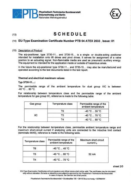
68 68 EB EN
Series 3730 Type Electropneumatic Positioner
 Series 3730 Type 3730-0 Electropneumatic Positioner Application Single-acting or double-acting positioner for attachment to pneumatic control valves Set point Travel 4 to 20 ma 5.3 to 200 mm The positioner
Series 3730 Type Electropneumatic Positioner
 Series 3730 Type 3730- Electropneumatic Positioner Application Single-acting or double-acting positioner for attachment to pneumatic control valves. Self-calibrating, automatic adaptation to valve and
T EN TROVIS Electropneumatic Positioner
 T 8484-1 EN TROVIS 3730-1 Electropneumatic Positioner Application Single-acting positioner for attachment to pneumatic globe and rotary valves. Self-calibrating, automatic adaptation to valve and actuator.
Series 3730 Electropneumatic Positioner Type
 Series 3730 Electropneumatic Positioner Type 3730-0 Application Single-acting or double-acting positioner for attachment to pneumatic control valves Reference variable Travels 4 to 20 ma 5.3 to 200 mm
Mounting and Operating Instructions EB EN ( ) Series 3730 Type Electropneumatic Positioner. with HART communication
 Series 3730 Type Electropneumatic Positioner. with HART communication") Series 3730 Type 3730-3 Electropneumatic Positioner with HART communication Old design Translation of original instructions New design Mounting and Operating Instructions EB 8384-3 EN (1300-1612) Firmware
Series 3730 Type 3730-3 Electropneumatic Positioner with HART communication Old design Translation of original instructions New design Mounting and Operating Instructions EB 8384-3 EN (1300-1612) Firmware
Series 3731 Type Electropneumatic Ex d Positioner with HART communication
 Series 3731 Type 3731-3 Electropneumatic Ex d Positioner with HART communication Application Single-acting or double-acting Ex d positioner for attachment to pneumatic control valves. Self-calibrating,
Series 3731 Type Electropneumatic Ex d Positioner with FOUNDATION TM fieldbus communication
 Series 3731 Type 3731-5 Electropneumatic Ex d Positioner with FOUNDATION TM fieldbus communication Application Positioners for attachment to pneumatic control valves Rated travels from 3.6 to 200 mm Opening
Mounting and Operating Instructions EB EN ( ) Series 3730 Type Electropneumatic Positioner
 Series 3730 Type Electropneumatic Positioner") Series 3730 Type 3730-6 Electropneumatic Positioner with HART communication and pressure sensors Old design New design Mounting and Operating Instructions EB 8384-6 EN (1300-1623) Firmware version 1.11
Series 3730 Type 3730-6 Electropneumatic Positioner with HART communication and pressure sensors Old design New design Mounting and Operating Instructions EB 8384-6 EN (1300-1623) Firmware version 1.11
Series 3730 Type Electropneumatic Positioner
 Series 3730 Type 3730-2 Electropneumatic Positioner Application Single-acting or double-acting positioner for attachment to pneumatic control valves. Self-calibrating, automatic adaptation to valve and
Data Sheet T EN
 Data Sheet T 8384-4 EN Series 3730 Type 3730-4 Electropneumatic Positioner with PROFIBUS-PA communication Application Positioners for attachment to pneumatic control valves Valve travel from 3.6 to 300
Series 3731 TROVIS SAFE Electropneumatic Ex d Positioner
 Series 3731 TROVIS SAFE 3731-3 Electropneumatic Ex d Positioner with HART communication Application Single-acting or double-acting Ex d positioner for attachment to pneumatic on/off valves in safety-instrumented
Series 3730 Type Electropneumatic Positioner with PROFIBUS-PA communication
 Series 3730 Type 3730-4 Electropneumatic Positioner with PROFIBUS-PA communication Application Positioners for attachment to pneumatic control valves Valve travel from 3.6 to 300 mm Opening angle 24 to
Series 3730 Electropneumatic Positioner Type with PROFIBUS-PA communication
 Series 3730 Electropneumatic Positioner Type 3730-4 with PROFIBUS-PA communication Application Positioner for attachment to pneumatic control valves Travels 3.6 to 200 mm Opening angle 24 to 100 Smart,
Data Sheet T EN
 Data Sheet T 8384-3 EN Series 3730 Type 3730-3 Electropneumatic Positioner with HART communication Application Single-acting or double-acting positioner for attachment to pneumatic control valves. Self-calibrating,
Data Sheet T 8493 EN. Series 3793 TROVIS 3793 Electropneumatic Positioner with HART communication
 Data Sheet T 8493 EN Series 3793 TROVIS 3793 Electropneumatic Positioner with HART communication Application Single-acting or double-acting positioner for attachment to pneumatic control valves. Self-calibrating,
Series 3730 Type Electropneumatic Positioner with PROFIBUS-PA communication
 Series 3730 Type 3730-4 Electropneumatic Positioner with PROFIBUS-PA communication Application Positioners for attachment to pneumatic control valves Rated travels from 3.6 to 200 mm Opening angle 24 to
Series 3793 TROVIS SAFE 3793 Electropneumatic Positioner with HART communication
 Series 3793 TROVIS SAFE 3793 Electropneumatic Positioner with HART communication Application Single-acting or double-acting positioner for attachment to pneumatic on/off valves in safety-instrumented systems.
Data Sheet T 8394 EN. Series 3725 Type 3725 Electropneumatic Positioner
 Data Sheet T 8394 EN Series 3725 Type 3725 Electropneumatic Positioner Application Single-acting positioner for attachment to pneumatic globe and rotary valves. Self-calibrating, automatic adaptation to
Series 3731 Electropneumatic Ex d Positioner Type with FOUNDATION TM Fieldbus communication
 Series 3731 Electropneumatic Ex d Positioner Type 3731-5 with FOUNDATION TM Fieldbus communication Application Positioner for attachment to pneumatic control valves Travel: 3.6 to 200 mm Opening angle:
Series 3730 Type Electropneumatic Positioner with HART communication and pressure sensors
 Series 3730 Type 3730-6 Electropneumatic Positioner with HART communication and pressure sensors Application Single-acting or double-acting positioner for attachment to pneumatic control valves. Self-calibrating,
Mounting and Operating Instructions EB EN ( ) Series 3730 Type Electropneumatic Positioner. with PROFIBUS-PA communication
 Series 3730 Type Electropneumatic Positioner. with PROFIBUS-PA communication") Series 3730 Type 3730-4 Electropneumatic Positioner with PROFIBUS-PA communication Old design New design Fig. 1 Type 3730-4 Mounting and Operating Instructions EB 8384-4 EN (1300-1613) Firmware version
Series 3730 Type 3730-4 Electropneumatic Positioner with PROFIBUS-PA communication Old design New design Fig. 1 Type 3730-4 Mounting and Operating Instructions EB 8384-4 EN (1300-1613) Firmware version
Electropneumatic Positioner Type and Type with HART communication
 Electropneumatic Positioner Type 3730-2 and Type 3730-3 with HART communication Application Single-acting or double-acting positioner for attachment to pneumatic control valves. Self-adjusting, automatic
Series 3730 Electropneumatic Positioner Type with HART communication and pressure sensors
 Series 3730 Electropneumatic Positioner Type 3730-6 with HART communication and pressure sensors Application Single-acting or double-acting positioner for attachment to pneumatic control valves. Self-calibrating,
Mounting and Operating Instructions EB EN. Series 3731 Type Electropneumatic Ex d Positioner. with HART communication
 Series 3731 Type 3731-3 Electropneumatic Ex d Positioner with HART communication Translation of original instructions Mounting and Operating Instructions Firmware version 1.61 Edition May 2017 EB + CD
Series 3730 Electropneumatic Positioner Type and Type with HART communication
 Series 3730 Electropneumatic Positioner Type 3730-2 and Type 3730-3 with HART communication Application Single-acting or double-acting positioner for attachment to pneumatic control valves. Self-calibrating,
Series 3730 Type Electropneumatic Positioner with HART communication
 Series 3730 Type 3730-3 Electropneumatic Positioner with HART communication Application Single-acting or double-acting positioner for attachment to pneumatic control valves. Self-calibrating, automatic
Series 3730 Electropneumatic Positioner Type and Type with HART communication
 Series 3730 Electropneumatic Positioner Type 3730-2 and Type 3730-3 with HART communication Application Single-acting or double-acting positioner for attachment to pneumatic control valves. Self-calibrating,
Mounting and Operating Instructions
 Mounting and Operating Instructions EB 8394 EN Translation of original instructions Series 3725 Type 3725 Electropneumatic Positioner Firmware version 1.12 Edition June 2014 Note on these mounting and
Series Electropneumatic Positioner Type and Type with HART communication
 Series 3730 Electropneumatic Positioner Type 3730-2 and Type 3730-3 with HART communication Application Single-acting or double-acting positioner for attachment to pneumatic control valves. Self-calibrating,
PROFIBUS-PA Positioner Type 3785
 PROFIBUS-PA Positioner Type 3785 Application Single-acting or double-acting PROFIBUS-PA positioner for attachment to pneumatic control valves. Rated travel from 7.5 to 120 mm Opening angle up to 120 Smart,
PROFIBUS Positioner Type PA Device Profile Version 3.0. Fig. 1 Type Mounting and Operating Instructions EB EN
 PROFIBUS Positioner Type 3785 PA Device Profile Version 3.0 Fig. 1 Type 3785 Mounting and Operating Instructions EB 8382-2 EN Firmware version R 1.42/K 2.12 Edition May 2007 Contents Contents Page 1 Design
97100 NAMUR series, 3/2 & 5/2 Indirect solenoid actuated spool valve
 9700 NAMUR series, / & / > > Port size: /4 (ISO G or NPT), NAMUR Interface > > Crossover-free switching > > Main application: Single and double acting actuators > > / way valve usable as / way valve >
FOUNDATION TM FIELDBUS Positioner Type Fig. 1 Type Mounting and Operating Instructions EB EN
 FOUNDATION TM FIELDBU Positioner Type 3730-5 Fig. 1 Type 3730-5 Mounting and Operating Instructions EB 8384-5 EN Firmware version K 1.1x/ R 1.4x Edition August 2005 Contents Contents Page 1 Design and
Pneumatic Control/Feedback
 897 /Feedback Type 897 can be combined with... Compact design Integrated pilot valve with manual override Internal control air routing Bright LED position indicator Automatic end position adjustment Type
Inductive sensor For rotary actuators NI4-DSU35TC-2Y1X2/S933
 ATEX category II 2 G, Ex zone 1 ATEX category II 1 D, Ex zone 20 SIL2 (Low Demand Mode) acc. to IEC 61508, PL c acc. to ISO 13849-1 at HFT0 SIL3 (All Demand Mode) acc. to IEC 61508, PL e acc. to ISO 13849-1
Pneumatic Control/Feedback
 897 /Feedback Type 897 can be combined with... Compact design Integrated pilot valve with manual override Internal control air routing Automatic end position adjustment With ATEX II cat. G/D and cat. D/G
Inductive dual sensor For rotary actuators NI4-DSU35TC-2Y1X2/S933
 ATEX category II 2 G, Ex zone 1 ATEX category II 1 D, Ex zone 20 SIL2 as per IEC 61508 Rectangular, housing DSU35 Plastic, PP-GF30-VO Two outputs for monitoring the position of rotary actuators Mounting
Inductive sensor For rotary actuators NI4-DSU35TC-2Y1X2
 ATEX category II 2 G, Ex zone 1 ATEX category II 1 D, Ex zone 20 SIL2 (Low Demand Mode) acc. to IEC 61508, PL c acc. to ISO 13849-1 at HFT0 SIL3 (All Demand Mode) acc. to IEC 61508, PL e acc. to ISO 13849-1
Material pressure (bar) (Cv (US) kv x 1,2 Seat
 (Cv (US) kv x 1,2 Seat") 00 / poppet valves electromagnetic actuated, directly controlled G /, / NPT or flanged with NAMUR Interface TÜV-approval based on IEC 6 08, DIN V Valves for safety systems up to SIL Solenoid valve also
00 / poppet valves electromagnetic actuated, directly controlled G /, / NPT or flanged with NAMUR Interface TÜV-approval based on IEC 6 08, DIN V Valves for safety systems up to SIL Solenoid valve also
Inductive sensor Dual sensors with extended temperature range NI4-DSU35TC-2Y1X2/S97
 ATEX category II 2 G, Ex zone 1 ATEX category II 1 D, Ex-zone 20 for temperatures up to -25 C SIL2 acc. to IEC 61508 Rectangular, housing DSU35 Plastic, PP-GF30-VO Two outputs for monitoring the position
Mounting and Operating Instructions EB EN. Electric Actuators Type 5824 without fail-safe action Type 5825 with fail-safe action
 Electric Actuators Type 5824 without fail-safe action Type 5825 with fail-safe action Three-step version Translation of original instructions Mounting and Operating Instructions EB 5824-1 EN Edition January
Sensor boxes SRBC. Festo core product range Covers 80% of your automation tasks
 Sensor boxes SRBC q/w Worldwide: Superb: Easy: Festo core product range Covers 80% of your automation tasks Always in stock Festo quality at an attractive price Reduces procurement and storing complexity
Pneumatic Control/Feedback
 897 /Feedback Type 897 can be combined with... Compact design Integrated pilot valve with manual override Internal control air routing Bright LED position indicator Automatic end position adjustment Type
97105 Inline 3/2, 5/2 & 5/3 way spool valves electromagnetic actuated, indirectly controlled G1/4, 1/4 NPT, G1/2, 1/2 NPT
 70 Inline 3/, / & /3 way spool valves electromagnetic actuated, indirectly controlled G/, / NPT, G/, / NPT Main application: single and double operated actuators TÜV-approval based on type examination
Operating pressure. N/en/en
 660, 8007 NAMUR /, / & / spool valves electromagnetic actuated, indirectly controlled G / and NAMUR interface For single and double operated actuators Manual override with and without detent Simple design
Technical Data. General specifications. Rated operating distance s n 3 mm
 0102 Model Number Features Direct mounting on standard actuators Compact and stable housing with terminal compartment connection ATEX & IECEX certifications Usable up to SIL 2 acc. to IEC 61508 Weatherproof
97105 Inline 3/2, 5/2 & 5/3 spool valves electromagnetic actuated, indirectly controlled G 1/4, 1/4 NPT, G 1/2, 1/2 NPT
 705 Inline 3/, 5/ & 5/3 spool valves electromagnetic actuated, indirectly controlled G /, / NPT, G /, / NPT For single and double operated actuators Valves for safety systems up to SIL (IEC 6508) Crossover-free
Digital electropneumatic positioner
 Digital electropneumatic positioner Type 879 can be combined with Compact metal housing Graphic display with backlight Easy start-up Comprehensive range of additional software functions Profibus DPV1 (optional)
Digital Positioner 8049
 Compact digital positioner for pneumatic control valves. Positioner can be integrated into valve actuator (no external moving parts for stroke feedback) Wide range of strokes - 8 mm No steady-state air
Type 6150 AS-Interface Module. Type 3372 Electropneumatic Actuator with AS-interface module. Mounting and Operating Instructions EB 6150 EN
 Type 6150 AS-Interface Module Type 3372 Electropneumatic Actuator with AS-interface module Mounting and Operating Instructions EB 6150 EN Edition July 2013 Definition of the signal words used in these
Operating pressure (bar)
") / poppet valves electromagnetic actuated, directly controlled G /4, /4 NPT, G /, / NPT or flanged with NAMUR Interface Main application: single operated actuators for plants Valves for safety systems up
/ poppet valves electromagnetic actuated, directly controlled G /4, /4 NPT, G /, / NPT or flanged with NAMUR Interface Main application: single operated actuators for plants Valves for safety systems up
Sensor boxes SRBE Key features and product range overview
 Sensor boxes SRBE Sensor boxes SRBE Key features and product range overview Function Sensor boxes SRBE are used for electrical feedback and control of the position of process valves actuated using pneumatic
3/2 Directional control valves Direct solenoid operated poppet valves Internal thread G 1/2, 1/2 NPT or flanged with NAMUR interface
 9805 / Directional control valves Direct solenoid operated poppet valves Internal thread G /, / NPT or flanged with NAMUR interface Main application: single operated actuators for plants TÜV-approval based
Positioner with HART Communication Type Fig. 1 Type Mounting and Operating Instructions EB EN
 Positioner with HART Communication Type 3780 Fig. 1 Type 3780 Mounting and Operating Instructions EB 8380-1 EN Firmware R 2.22/K 2.23 Edition June 2004 Contents Contents Page 1. Design and principle of
97105 NAMUR. Technical data. Ordering information and accessories See page 6 and 7
 90 NAMUR /, / and / directional valves Actuation: electromagnetic Indirectly controlled soft seal spool valves Port size: G /, / NPT, G /, / NPT NAMUR-interface For single and double operated actuators
26360, NAMUR. Technical data
 66, 87 NAMUR /-, /- and / directional control valves Operation: elektromagnetic Indirectly controlled soft seal spool valves Port size: G/ NAMUR-Interface For single and double operated actuators Manual
Inductive sensor For rotary actuators NI4-DSU35-2Y1X2-H1140
 ATEX category II 2 G, Ex zone 1 ATEX category II 1 D, Ex zone 20 SIL2 (Low Demand Mode) acc. to IEC 61508, PL c acc. to ISO 13849-1 at HFT0 SIL3 (All Demand Mode) acc. to IEC 61508, PL e acc. to ISO 13849-1
SRD991 Intelligent Positioner with HART, FoxCom, PROFIBUS-PA, FOUNDATION Fieldbus H1 or Without Communication
 R V Data Sheet 12.07 DS EVE0105 -(en) SRD991 Intelligent Positioner with HART, FoxCom, PROFIBUS-PA, FOUNDATION Fieldbus H1 or Without Communication The intelligent positioner SRD991 is designed to operate
HERION SERIES Indirect solenoid actuated spool valves
 HERION SERIES Indirect solenoid actuated spool valves for single and double acting actuators with NAMUR interface /2, /2, /, NC/APB, G/, G/2 Valves for safety systems up to SIL (IEC 08) Crossover-free
Digital electropneumatic positioner
 Digital electropneumatic positioner Type 879 can be combined with Compact metal housing Graphic display with backlight Easy start-up Comprehensive range of additional software functions Profibus DPV1 (optional)
Indicating Digital Transmitter for Differential Pressure and Flow. Media 6 with LCD Media 6 with LED
 Indicating Digital Transmitter for Differential Pressure and Flow Media 6 with LCD Media 6 with LED Application Microprocessor-controlled transmitter for measuring and indicating the differential pressure
Material Seat seal. N/en
 0 / poppet valves electromagnetic actuated, directly controlled G /, / NPT or flanged with NAMUR interface TÜV-approval based on IEC 6 8 Valves for safety systems up to SIL Standard NAMUR type - redundancy:
TZID-C. Intelligent Positioner. Operating Instructions 42/18-64 EN Rev. 4.0 TZID-C
 TZID-C Intelligent Positioner Operating Instructions 42/18-64 EN Rev. 4.0 % TZID-C Mounting to linear actuators 1. 2. 3. 4. Mounting to rotary actuators 1. 2. M6 screws 3. 4 M5 screws Brief operating instructions
Operating pressure. N/en/en
 660, 8007 NAMUR /, / & / way spool valves electromagnetic actuated, indirectly controlled G / and NAMUR interface For single and double operated actuators Manual override with and without detent Simple
SideControl Positioner
 SideControl Positioner Electropneumatic positioner for pneumatically actuated process valves II (1) 2 G EEx ia IIC T6 approval can be combined with... Type 2712 Globe valve Globe valve acc. to NAMUR/IEC
21023, 21025, 2/2 Direct solenoid actuated poppet valves
 03, 05, / > > Port size: G/4, G/ > > Working from 0 bar up > > Suitable for mediumhigh vacuum down to.33 0 - mbar l/s > > Compact design > > Valves and solenoids are ATEX approved. Additional international
24011 series, 3/2 Direct solenoid actuated poppet valve
 0 series, / > Port size: / (ISO G or NPT), NAMUR Interface > Add-on manual override or inductive limit switches on request > Main application: Single and double acting actuators > TÜV-approval based on
Inductive angle sensor with analog output Ri360P1-DSU35TC-ELi-Exi
 ATEX category II 2 G, Ex Zone 1 ATEX category II 2 D, Ex Zone 21 Rectangular, housing DSU35 Plastic, PP-GF30-VO Detection of angular range 0 to 360 P1-Ri-QR14 positioning element included in delivery Measuring
Digital electropneumatic Positioner SideControl
 Digital electropneumatic Positioner SideControl Type 8791 BASIC can be combined with Compact and robust design Easy to start using tune function Dynamic positioning system with no air consumption in controlled
YT-870 / 875 Series. Rotork YTC Limited VERSION 1.06
 PRODUCT MANUAL Rotork YTC Limited VERSION 1.06 Contents 1 Introduction... 3 1.1 General Information for the users... 3 1.2 Manufacturer Warranty... 3 1.3 Explosion Proof Warning... 4 2 Product Description...
Digital electropneumatic positioner SideControl
 Digital electropneumatic positioner Type 879 can be combined with Compact and robust design Easy to start using tune function Integrated diagnostic functions for valve monitoring (optional) Dynamic positioning
Technical features. N/en
 /, 5/ & 5/ spool valves electromagnetic actuated, indirectly controlled G /, / NPT, G /, / NPT or flanged with NAMUR interface For single and double operated actuators Exhaust air recirculation at way
VALVES Inline 3/2-, 5/2- & 5/3 Spool valves electromagnetic actuated, indirectly controlled G 1/4, 1/4 NPT, G 1/2, 1/2 NPT
 975 Inline 3/-, 5/- & 5/3 Spool valves electromagnetic actuated, indirectly controlled G /, / NPT, G /, / NPT For single and double operated actuators Closed crossover design Add-on manual override Rectified
Digital electropneumatic Positioner for the integrated mounting on process control valves
 Digital electropneumatic Positioner for the integrated mounting on process s Type 8694 can be combined with Automatic teach function Contact-free position sensor Compact stainless steel design AS-Interface
Technical features. 12/ f. N/en
 /, / & / way spool valves electromagnetic actuated, indirectly controlled G /, / NPT, G /, / NPT or flanged with NAMUR interface Main application: single and double operated actuators TÜV-approval based
Technical Information Promonitor NRF560
 TI00462G/08/EN/03.14 71264171 Products Solutions Services Technical Information For tank side monitor and control of Proservo NMS5 intelligent tank gauge Application is a monitoring unit for use with Proservo
Pneumatic Control Unit for the integrated mounting on process valves
 Pneumatic Control Unit for the integrated mounting on process valves Type 890 can be combined with Compact design Pilot valve with high air flow rate Internal control air channel Optical position indicator
97105 NAMUR, 3/2, 5/2 & 5/3 Indirect electromagnetic actuated spool valves
 970 NAMUR, /, / & / > > Port size: / or / ISO G/NPT > > Main application: single and double operated actuators > > TÜV-approval based on type examination DIN EN, DIN 9 and IEC 08 > > Valves for safety
Sensor boxes SRBG Key features
 Key features Function SRBG sensor boxes are the compact solution when it comes to electrical feedback signals and monitoring the position of process valves which are actuated with pneumatic quarter turn
95100, 2/2 (stainless steel) Direct solenoid actuated poppet valves
 Direct solenoid actuated poppet valves") 9500, / (stainless steel) > > Port size: G/8, G/4, /4 NPT > > Working from 0 bar up > > Assembled free of oil and grease > > Suited for fine vacuum down to,33 0 - mbar > > For a.c. solenoid systems with
9500, / (stainless steel) > > Port size: G/8, G/4, /4 NPT > > Working from 0 bar up > > Assembled free of oil and grease > > Suited for fine vacuum down to,33 0 - mbar > > For a.c. solenoid systems with
Operating pressure (bar) kv factor (m 3 /h) *3)
 kv factor (m 3 /h) *3)") / way poppet valves (stainless steel) electromagnetic actuated, directly controlled G /8, G /4 or /4 NPT Working from 0 bar up Assembled free of oil and grease Suited for fine vacuum down to,33 0 - mbar
/ way poppet valves (stainless steel) electromagnetic actuated, directly controlled G /8, G /4 or /4 NPT Working from 0 bar up Assembled free of oil and grease Suited for fine vacuum down to,33 0 - mbar
Assembly. Front view. LED yellow: Relay output. LED red: LB/SC Power Rail
 Switch Amplifier Features Assembly -channel isolated barrier 4 V DC supply (Power Rail) Dry contact or NAMUR inputs Relay contact output Line fault detection (LFD) Reversible mode of operation Up to SIL
Mounting and Operating Instructions EB EN. Electric Actuators with LON Interface. Type 5824 without Type 5825 with fail-safe action
 Electric Actuators with LON Interface Type 5824 without Type 5825 with fail-safe action Fig. 1 Type 5824 Actuator Mounting and Operating Instructions EB 5824-9 EN Edition June 2003 Contents Contents Page
26360, Inline. Technical data. Ordering information See page 2. For connector plugs see page 2 and data sheets N/en /2 5/2.
 66, 87 Inline / and 5/ directional control valves NG 6 and Operation: elektromagnetic Indirectly controlled soft seal spool valves Port size: G /4 and G / For single and double operated actuators Manual
Universal Tristop Cylinder for Cam Brakes
 Tristop for Cam Brakes 3rd Edition This publication is not subject to any update service. New versions are available in INFORM at www.wabco-auto.com Copyright WABCO 2006 Vehicle Control Systems An American
Inductive sensor BI1.5-EG08-Y1-H1341
 ATEX category II 1 G, Ex zone 0 ATEX category II 1 D, Ex zone 20 SIL2 (Low Demand Mode) acc. to IEC 61508, PL c acc. to ISO 13849-1 at HFT0 SIL3 (All Demand Mode) acc. to IEC 61508, PL e acc. to ISO 13849-1
Series 95000, 2/2 Direct solenoid actuated poppet valve
 > Port size: /4 (ISO G or NPT), G/ > Working from 0 bar up > Short switching times > Suited for fine vacuum down to,33 x 0 - mbar > For a.c. solenoid systems with integrated rectifier (40... 60 Hz) > Variable
Do not open when energized or when an explosive atmosphere is present. Electrostatic hazard, clean only with damp cloth.
 D460/D470 Series - ATEX certified position transmitter nnnn II 2 GD ITS 11 ATEX 17431X Ex d IIC T* Gb Tamb -*ºC to +*ºC Ex tb IIIC T* Db Tamb -*ºC to +*ºC IP6X Ambient variation -60 C to +110 C (T4/T130
Inductive Angle Sensor With Analog Output RI360P1-DSU35TC-ELI-EXI
 ATEX category II 2 G, Ex Zone 1 ATEX category II 2 D, Ex Zone 21 Rectangular, housing DSU35 Plastic, PP-GF30-VO Detecting angular positions of 0 to 360 P1-Ri-DSU35 positioning element included in delivery
Digital electropneumatic positioner
 Digital electropneumatic positioner Type 879 can be combined with Compact and robust design Easy to start using tune function Dynamic positioning system with no air consumption in controlled state Profibus
T 9510 EN Media 7 Differential Pressure Meter with remote data transmission
 T 9510 EN Media 7 Differential Pressure Meter with remote data transmission Application Microprocessor-controlled transmitter with dp cell for measuring and indicating the differential pressure, pressure,
Emergency Luminaire for Fluorescent Lamps Series EXLUX 6009
 > As wall, ceiling and pendant light fitting or pole mounted light fitting > Version with 2 lamps: 18 W and 36 W > Central locking > All-pole disconnection via N/C switch when opening light fitting or
BVS 17 ATEX E 117 X / IECEx BVS X Types 3320, 3321, 3323, 3360, 3361, 3363 AE3320, AE3321, AE3323, AE3360, AE3361, AE3363
 BVS 17 ATEX E 117 X / IECEx BVS 17.0100X Types 3320, 3321, 3323, 3360, 3361, 3363 AE3320, AE3321, AE3323, AE3360, AE3361, AE3363 Electromotive control valve with ATEX approval and IECEx approval Elektromotorisches
Inductive sensor BI1.5-EG08-Y1-H1341
 ATEX category II 1 G, Ex zone 0 ATEX category II 1 D, Ex zone 20 SIL2 (Low Demand Mode) acc. to IEC 61508, PL c acc. to ISO 13849-1 at HFT0 SIL3 (All Demand Mode) acc. to IEC 61508, PL e acc. to ISO 13849-1
SIWAREX JB Aluminum Housing. Instruction Manual Edition 03/2006
 s SIWAREX JB Aluminum Housing Instruction Manual Edition 03/2006 Table of Contents Table of Contents... 2 Warning and Safety Terms... 3 General... 4 1 Technical Description... 5 1.1 Area of Application...
ERNG-X. Description. Applications. ERNG-X Specifications DERNG2108X012
 ERNG-X DERNG2108X012 Description The ERNG-X is a steady state no bleed engineered system for accurate and reliable control of Natural Gas. The ERNG-X includes a pressure regulator, preconditioning filters,
LMP 308. Separable Stainless Steel Probe. Stainless Steel Sensor. accuracy according to IEC 60770: standard: 0.35 % FSO option: 0.25 % FSO / 0.
 LMP 08 Separable Stainless Steel Sensor accuracy according to IEC 60770: standard: 0.5 % FSO option: 0.25 % FSO / 0. % FSO Nominal pressure from 0... mh 2 O up to 0... 250 mh 2 O Output signals 2-wire:
Operating Instruction
 Level and Pressure Operating Instruction VEGASWING 71 A Contents Contents Safety information... 2 1 Product description 1.1 Function and configuration... 3 1.2 Functional principle... 3 1.3 Technical data...
Positioner CMSX-...-C-U-F1-...
 Positioner CMSX-...-C-U-F-.... CMSX-SE-... (linear) 5 Festo AG & Co. KG Postfach Esslingen Germany +9-0 www.festo.com (en) Operating instructions 80595 0a [80595] aj 9 8 Housing cover Inspection window
4 Remote I/O. Digital Output Module 8-Channel Version Type 9475/ from Rev. F
 4 Remote I/O Digital Output Module 8-Channel Version 8 channels for Ex i solenoid valves, piezo and booster-valves Intrinsically safe Ex ia IIC outputs Additional input for Plant-STOP available (acc. to