G3 Series DeviceNet TM Technical Manual
|
|
|
- Scot Jennings
- 5 years ago
- Views:
Transcription


1 G3 Series DeviceNet TM Technical Manual
2 Table of Contents G3 Series DeviceNet Technical Manual PAGE About DeviceNet... 3 Overview... 3 G3 DeviceNet Features... 3 Cabling and Drop Line Lengths (as defined by DeviceNet specification)... 3 G3 Introduction... 4 G3 Electronics Modularity... 5 Discrete I/O... 5 Pneumatic Valve Manifold... 6 Manifold Connectors... 7 Solenoid Coil Connections using Z-Board TM Technology for 2005/2012/2035 valve series... 7 Z-Board Connectors... 8 Z-Board and Ribbon Cable Example... 9 Z-Board with Valve Side Sub-D Example Communication Module (Node) DeviceNet Communication Module Communication Module Description Connector Pin-Outs Electrical Connections Standard Power Connector Wiring Diagram Examples Ground Wiring Power Consumption External Fuse Sizing Chart Diagnostics Communication Module LED Functions Output / Protection Diagnostic Bits G3 Node Graphic Display Network Address Sub-Menu Baud Rate Sub-Menu I/O Size - Coils Sub-Menu I/O Size - Allocation Menu I/O Size - Allocation Sub-Menu Cont DeviceNet with Quick Connect Sub-Menu Advanced Settings - I/O Diag. Menu Advanced Settings Node Diagnostics (Diagnostic Word) Advanced Settings - Fault Action Advanced Settings - Idle Action Advanced Settings - Brightness Advanced Settings Parameters Factory Defaults Diagnostics - Self Test Mode Diagnostics Cont Error Messages MCM Manual Configuration Module DIP Switch Settings ARM Auto Recovery Module Distribution Sub-Bus Distribution Modules Sub-Bus OUT Module Sub-Bus IN Modules Terminator Module Sub-Bus Valve Module Digital I/O Modules Digital I/O Module Rules Page 1
3 I/O Module Descriptions & Menus I/O Module Technical Data Digital Input Modules One Digital Input per Connector - M12 Female Modules Two Digital Inputs per Connector - M12 Female Modules Sixteen Digital Inputs Terminal Strip Modules Digital Output Modules One Digital Output per Connector - M12 Female Modules Two Digital Outputs per Connector - M12 Female Modules Two Digital High Current Outputs per Connector - M12 Female Modules Sub-Bus Valve Module Digital Input/Output Modules Two Digital I/O per Connector - M12 Female Modules Valve Side Digital Output Modules Sixteen Outputs per Connector - Sub-D 25 Pin Female Module I/O Modules I/O Module Rules Channel I/O - M12 Female Modules One Input per Connector - M12 Female Modules One I/O per Connector - M12 Female Modules G3 Graphic Display Module / I/O Mapping Module / Module Number Module / Alarm Settings Module / Description Module / Part number Module / Firmware Module / Brightness Module / Self Test Mode Module / Factory Defaults DeviceNet Configuration and Mapping EDS File I/O Message Types User Configurable Device Parameters Explicit Messaging Communication Fault/Idle Mode Parameter Communication Fault/Idle Mode Sequence DeviceNet Mapping I/O Sizes - Rx/Tx Manifold and I/O Data Sizing Worksheet Valve Side Discrete I/O Side Example No Example No Example No Example No Example No Appendix System Specifications Factory Default Settings Troubleshooting Glossary of Terms Technical Support Page 2
4 About DeviceNet Overview G3 Series DeviceNet Technical Manual DeviceNet is a serial communication protocol used to network industrial devices to eliminate labor intensive and expensive point to point wiring schemes. It is based on the CAN (Controller Area Network) protocol. Allen Bradley originally developed DeviceNet, but it is now supported by a multitude of manufacturers. The ODVA (Open DeviceNet Vendor Association) is an independent organization that governs the DeviceNet specification and oversees conformance testing for products, which will be used in a DeviceNet system. DeviceNet uses a powered 4-wire (plus shield) network and can have up to 64 nodes. The protocol can transfer a maximum of 8 bytes of data per node cycle with three selectable communication (baud) rates of 125 Kbps, 250 Kbps, or 500 Kbps. Maximum distance is dependent upon baud rate and cable media type. Refer to the section below for details. More information about DeviceNet and ODVA can be obtained from the ODVA web site G3 DeviceNet Features Features Description DeviceNet Spec. Supported Designed to DeviceNet Specification Revision 2.0 Bus Topology Straight with restricted drops; trunkline-dropline configuration Baud Rates Supported 125 Kbps, 250 Kbps and 500 Kbps and Autobaud Duplicate address detection If duplicate address detected on power up, duplicates will not progress to run mode Error Correction Yes, if error detected, sender is requested to repeat the message Address Setting Via graphic display, software, or optional Manual Configuration Module (MCM) Termination Resistor (external) A 121 ohms, 1%, ¼ Watt resistor is required at each end of the trunk line ADR support Auto-Device Replacement is supported when the MCM is not present Connection Types Supported Polled, Cyclic, Change of State (COS) or Combinations Conformance Tested Tested by ODVA for conformance Cabling and Drop Line Lengths (as defined by DeviceNet specification) Maximum Main Trunk Cable Length Baud Rate Thick Trunk Cable Thin Trunk Cable Flat Trunk Cable 125 Kbps 1640 ft (500 m) 328 ft (100 m) 1246 ft (380 m) 250 Kbps 820 ft (250 m) 328 ft (100 m) 656 ft (200 m) 500 Kbps 328 ft (100 m) 328 ft (100 m) 246 ft (75 m) Maximum Drop Line Cable Length Baud Rate Maximum Drop Length Cumulative Drop Length 125 Kbps 20 ft (6 m) 512 ft (156 m) 250 Kbps 20 ft (6 m) 256 ft (78 m) 500 Kbps 20 ft (6 m) 128 ft (39 m) Page 3

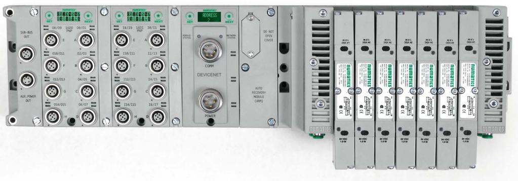
5 G3 Introduction G3 Series DeviceNet Technical Manual The G3 Series is an electronic platform that features an integrated graphic display for simple commissioning and displaying of diagnostic information. In addition it has an innovative distribution capability which allows the same I/O components that make up a centralized manifold configuration to be used as the distribution components as well, decreasing the need for duplicate components on centralized and distributed applications. The G3 platform interfaces to a variety of valve series and fieldbus interface protocols and is capable of addressing a total of 1200 I/O points (150 bytes). With proper assembly and termination the G3 modules will have an IP65 / IP67 rating. The manifold can be viewed as having two sections to it, the Valve Side and the Discrete I/O Side. The Valve Side supports a maximum of 32 solenoid coils and the Discrete I/O Side supports a maximum of 16 modules capable of addressing up to 1200 outputs, 1200 inputs or various combinations (current physical I/O combinations allows 1200 I / 544 O). Various discrete modules with integrated graphic display are available. They include digital I/O, analog I/O, and specialty modules which cover various application needs. Pin-outs for all connectors are labeled on the side of the respective modules and are also detailed in the module section of this document. This manual details specific information for configuring and commissioning the Numatics G3 Series product line. For more information relating to pneumatic valving and valve manifold assemblies, please refer to the Numatics In Control Catalog at Clips Allows easy field changes of electronic modules. Graphic Display Allows Easy Configuration & Diagnostic reporting ARM (Auto Recovery Module) Automatically stores & reprograms configuration information Sub-Bus OUT Used to distribute additional I/O and manifolds Discrete I/O Side Accepts up to 16 modules in centralized or distributed configuration Communication Module (Node) Available with various Industrial protocols Valve Side Drives up to 32 coils Page 4

6 G3 Electronics Modularity Discrete I/O The G3 Series product line is a completely modular and scalable system. As shown below, all of the G3 electronic modules plug together, via mechanical clips, allowing for easy assembly and field changes. Page 5
7 Pneumatic Valve Manifold G3 Series DeviceNet Technical Manual The pneumatic valve manifold with internal circuit board technology is also modular. The valve solenoid coil connections are automatically made using Z-Board technology (plug together PC boards), which allow internal connection from solenoid coils to output drivers without the use of wires). This allows easy assembly and field changes. Page 6

8 Manifold Connectors Solenoid Coil Connections using Z-Board TM Technology for 2005/2012/2035 valve series Z-Board plug together technology connects all valve solenoids to the valve coil output driver board, located in the valve adapter. The 32 available coil outputs are divided into 2 separate connector groups. Output group No. 1 is comprised of the first output word, bits 0-15, and output group No. 2 is comprised of the second output word, bits Output group No. 1 connects directly to the Z-Boards. Output group No. 2 is connected to the Z-Boards via an internal ribbon cable or valve side Sub-D module. The first output (bit 0) connects to the 14 (A) solenoid on the valve closest to the communication node. The 17 th 32 nd solenoids interconnect via the Z-Boards to output group No. 2. For the maximum capability of 32 solenoids on the same manifold, the 16 th and 17 th solenoid coils must NOT be on the same sub-base. Output Group No. 1 Output Group No. 2 Plug-in Manifold with Intergral "Z-Board" Eliminates Wiring Earth Ground Pin No. 3 14(A) Solenoid Pin No. 1 SINGLE "Z-BOARD" DOUBLE "Z-BOARD" SINGLE "Z-BOARD" DOUBLE "Z-BOARD" Common Pin No. 4 12(B) Solenoid Pin No. 2 NOTE! A single solenoid valve s coil is always on the 14 end. Page 7
9 Z-Board Connectors The 2005/2012/2035 valve series utilize 2 different Z-Board designs to achieve the single and double solenoid output functions. This yields the possible 32 single, 16 double, or various combinations of valve coil output capabilities. Single Z-Board Double Z-Board Ribbon Connection Single Z-Board Ribbon Connection Double Z-Board single double NOTE! The 17 th solenoid (output group No. 2 s first bit) must be accessed via either the valve side Sub-D output module or a ribbon connector type Z-board. Page 8
10 Z-Board and Ribbon Cable Example G3 Series DeviceNet Technical Manual If fourteen (14) single solenoid and one (1) double solenoid valves are connected directly to the communication node via their Z-Boards, and one (1) single solenoid and four (4) double solenoid valves are connected to the communication node via the ribbon cable, the following would be the valve side bit map: Output Group No. 1 2 Output Word 0 1 Output Byte Output Bit No Solenoid Coil n/a Output No. NOTE! In the above example, Output Bits No. 25 thru No. 31 are allocated but not used. Allocation may be changed by configuration changes in the communication module (node). Refer to page 24 in this manual. Page 9
11 Z-Board with Valve Side Sub-D Example G3 Series DeviceNet Technical Manual If sixteen (16) single solenoid valves are connected directly to the communication node via their Z-Boards, and a valve side Sub-D connector is connected to the communication node via the output Group No. 2 connector then the following would be the valve side bit map: Output Group No. 1 2 Output Word 0 1 Output Byte Output Bit No Solenoid Coil Output No. Page 10
12 Communication Module (Node) DeviceNet Communication Module This module is the communication interface to the manifold. It contains communication electronics and internal short circuit protection for power. It can be configured via software, via the graphic display or manually via DIP switches through the optional Manual Configuration Module (MCM). The Numatics G3 DeviceNet node is tested by the ODVA to ensure DeviceNet compatibility and interoperability. The G3 DeviceNet node supports Polled, Change of State (COS), Cyclic and Combination (i.e. Outputs can be set for Polled while Inputs can be set for COS for greater system response time) I/O Message types. DeviceNet Quick Connect functionality is also user selectable in this unit. Communication Module Part Number DeviceNet Communication module Page 11
13 Communication Module Description G3 Series DeviceNet Technical Manual Detail No. Description 1 Set Button used to navigate through user menus and to set parameters 2 Module LED 3 5 Pin MINI Male Communication Connector per ODVA specification 4 Mounting Hole 5 Next Button used to navigate through user menus and to set parameters 6 Graphic Display used to display parameter information 7 Network LED 8 Slot for text ID tags 9 Keying for preventing I/O module insertion 10 4 Pin MINI Male Power Connector Page 12


14 Connector Pin-Outs Industry standard 7/8 MINI connectors are used for communication and power. The DeviceNet communication connector is a single keyway 5 pin male connector. The Power connector is a single keyway 4 pin male connector. DeviceNet Communication Connector Pin-Out Pin No. Function Description 1 Shield Cable shield 2 V+ Bus Power 11-25VDC 3 V- Bus Power Common (0 VDC) 4 CAN_H Controller Area Network High Communication Line 5 CAN_L Controller Area Network Low Communication Line Power Connector with CENELEC Style Pin-Out CENELEC Pin No Function Description +24 VDC Voltage used to power outputs (Valves and Outputs) (valve coils and discrete outputs) SW +24 VDC Voltage used to power discrete inputs and (Node and Inputs) node electronics UNSW 0 VDC Common 0 VDC (-V) Voltage used to power discrete inputs and (Node and Inputs) node electronics UNSW 0 VDC Common 0 VDC Voltage used to power outputs (Valves and Outputs) (valve coils and discrete outputs) SW! Power common (0 VDC) pins 3 and 4 are isolated from each other to allow separate (isolated) power supply connection if required. However, they can be tied together if a single common, non-isolated, application is preferred. The draw of the +24VDC Valves and Outputs and +24VDC Node and Inputs pins cannot exceed 8 Amps, at any given moment in time. The Node and Inputs pins supplies power to the node electronics. These pins must be powered at all times for communication node to be functional. Page 13

 Male")
15 Electrical Connections Standard Power Connector Wiring Diagram Examples Single Power Supply Example (Non-isolated commons) Male connector view Separate Power Supply Example (Non-isolated commons) Male connector view Page 14
16 Separate Power Supply Example (Isolated commons) Male connector view! Please see page 18 for external fuse sizing guide. When using molded connector power cables, Do Not rely on wire colors for Pin-Out. Always use pin number references. Page 15

17 Ground Wiring All Numatics Inc. communication nodes should be grounded during the installation process. These grounding guidelines can be found in National Electrical code IEC or EN CHASSIS GROUND CONNECTION POINTS! Proper grounding will alleviate and prevent many intermittent problems with network communication. When grounding to a machine frame, please ensure that the machine frame itself is already properly grounded. Better grounding can be achieved when larger diameter (lower gauge) wire is used. Page 16
18 Power Consumption Power Connection CENELEC Pin No Function Description +24 VDC Voltage used to power outputs (Valves and Outputs) (valve coils and discrete outputs) SW +24 VDC Voltage used to power discrete inputs and (Node and Inputs) node electronics UNSW 0 VDC Common 0 VDC (-V) Voltage used to power discrete inputs and (Node and Inputs) node electronics UNSW 0 VDC Common 0 VDC (-V) Voltage used to power outputs (Valves and Outputs) (valve coils and discrete outputs) SW Power Rating The maximum system current capability is 8 Amps. Care should be taken not to exceed 8 Amp draw through the Aux. power connector pins. Discrete I/O current draw is dependent on the device(s) connected. It is critical to know what these values are in order to remain safely within the 8 Amp limitations (4 Amps if using distribution). Loads should not draw more than 0.5 Amps of current from any one individual discrete output point (Contact factory for higher current capability requirements). +24VDC +24VDC Component Voltage Tolerance (Valves and Outputs) (Node and Inputs) Pins 1 & 4 Pins 2 & 3 Current Power Current Power Solenoid 2002 (Each) 24 VDC +10%/-15% A 0.5 W 0 A 0 W Solenoid 2005 (Each) 24 VDC +10%/-15% A 1.35 W 0 A 0 W Solenoid 2012 (Each) 24 VDC +10%/-15% A 2.5 W 0 A 0 W Solenoid 2035 (Each) 24 VDC +10%/-15% A 2.5 W 0 A 0 W Solenoid ISO - SPA 24 VDC +10%/-15% A 4.0 W 0 A 0 W Valve Adapter (Driver) 24 VDC +/- 10%.068 A 1.63 W 0 A 0 W Discrete Digital Input Module 24 VDC +/- 10%.012 A.29 W.085 A* 2.04 W* Discrete Digital Output Module 24 VDC +/- 10%.051 A 1.2 W.060 A* 1.44 W* Discrete Digital I/O Module 24 VDC +/- 10%.035 A 0.84 W.076 A* 1.82 W* Discrete Module (V & C) 24 VDC +/- 10%.020 A W.070 A* 1.85 W* Communication Module (Node) DeviceNet Network Current = 24 VDC +/- 10%.006 A W.070 A* 1.7 W* Sub-Bus Valve Module 24 VDC +/- 10% 0 A 0 W.032 A* 0.77 W* Auto Recovery Module (ARM) 24 VDC +/- 10% 0 A 0 W.022 A.53 W Manual Configuration Module (MCM) 24 VDC +/- 10% 0 A 0 W.022 A.53 W * Current depends on graphic display brightness setting. Max. value shown with high brightness. Values decrease by approx. 12% for Medium and 25% for Low brightness settings. NOTE! Total power consumption for each Discrete I/O point is dependent on the specific current draw of input sensor devices and output loads. Recommended External Fuses Page 17
19 External fuses should be chosen based upon the physical manifold configuration. Please refer to table below for the fuse sizing chart. External Fuse Sizing Chart Power Consumption - Power Connector Pin for Valves and Outputs Description Current Number of Solenoid s Energized Simultaneously X A (ISO SPA Series) = Amps X A (2012, 2035 and ISO mm Series) = Amps X A (2005 and ISO mm series) = Amps X A (2002 Series) = Amps Total load current drawn by simultaneously energized Discrete Outputs = Number of I/O modules installed X A = + Amps + Amps + Valve Adapter =.068 Amps + Communication Node Power Consumption =.008 Amps + Total: Amps Surge Compensation: X 1.25 Suggested External +24 VDC (Valves and Outputs) Fuse Value: Amps Power Consumption Power Connector Pin for Node and Inputs Description Current Communication Node Power Consumption =.068 Amps + Total load current drawn by Sensor Devices from s source = Amps + Number of I/O modules installed X A = Amps Total: Amps Surge Compensation: X 1.25 Suggested External Pin +24 VDC (Node and Inputs) Fuse Value: Amps + NOTE! The Node and Inputs Aux Power pins supply power to the node electronics. These pins must be powered at all times for communication node and Inputs to be functional. The internal electronic fuses exist to protect against damage due to catastrophic failure of internal components. External fuses are always recommended for protection against power supply failure, over-current conditions, etc Page 18
20 Diagnostics Communication Module LED Functions Upon power up, the Module and Network LEDs indicate the state of the unit. There are two LEDs on the G3 DeviceNet node. The LEDs functions are described in the table below. LED Name Color Description Off OFF Device is not on-line; Bus power not applied if Module also flashing green; Physical problem with network; Improper baud rate. Normal operation. ON Green Device is on-line and has established a connection. NETWORK FLASHING Device is on-line but has no established connections. STATUS The device has detected a bus error that has rendered it incapable ON of communicating on the network; Duplicate MAC ID; Bus Off Red condition; Physical problem with network. FLASHING Communication failure one or more I/O connections have timed out. MODULE STATUS Off OFF Critical hardware fault. Microprocessor is not running. ON Normal operation. The device is operating properly. Green FLASHING Network power is absent. Green Red FLASHING Module is in self-test mode. Cycle power to end self-test mode. Page 19
21 Output / Protection Diagnostic Bits Diagnostic Bit Action during Fault Condition Output Type Valve Solenoid Coil Driver Valve Solenoid Coil Driver Discrete Outputs Output State ON OFF ON Fault Condition Bit No Fault 0 Fault -, Over Temp/Over Current 1 No Fault 0 Fault - Open Load 1 No Fault 0 Fault -, Over Temp/Over Current 1 Page 20
.")
22 G3 Node Graphic Display G3 Series DeviceNet Technical Manual The G3 Communication and I/O modules have an integrated graphic display that may be used to configure the parameters of the modules as well as showing diagnostic information. The following graphic displays represent the main menu selections of the DeviceNet communication module (node). Use the NEXT button to scroll through the Main menu headings shown below. At this level pressing the SET button allows access to the Sub-Menus. Please see the appropriate pages referenced below for further details and descriptions of the Sub-Menus. Note that many of these settings can also be adjusted via software with EDS file parameters. NOTE: WHEN A NETWORK I/O CONNECTION IS ESTABLISHED MANUAL CHANGES TO NODE PARAMETERS ARE NOT ALLOWED! Home Screen ADDRESS 45 BAUD RATE 125K I/O SIZE RX=12 TX=4 DEVICENET ADVANCED SETTINGS FACTORY DEFAULTS DIAGNOSTICS See page 22 for Sub Menu See page 23 for Sub Menu See page 24 for Sub Menu See page 27 for Sub Menu See page 28 for Sub Menu See page 33 for Sub Menu See page 35 for Sub Menu Page 21
23 Network Address Sub-Menu G3 Series DeviceNet Technical Manual ADDRESS 45 Steps to Set Address 1. Press the SET button to enter the ADDRESS sub-menu. SET ADDRESS 45 SET ADDRESS Press the NEXT button to scroll through the choices for the tens digit of the node address. Press the SET button to select the tens digit and move into the ones digit selection. 3. Press the NEXT button to scroll through the choices for the ones digit of the node address. Press the SET button to select the ones digit. ACCEPT 45 Y N ACCEPT 45 Y N 4. Press the NEXT button to select Yes or No to accept the address shown on the display, a. Selecting No will bring you back to the main Address menu. b. Selecting Yes will take you to the following SAVE SETTINGS menu. Press the SET button to confirm your choice. SAVE SETTINGS NOW LATER 5. Press the NEXT button to select either NOW or LATER. a. Selecting NOW will cause the node to reset and apply the new setting. b. Selecting LATER will cause the new Address to be saved in temporary memory, and allow you to make additional parameter changes before the node is reset. However, you must ACCEPT the saved changes before your next power cycle otherwise they will be lost. Press the SET button to confirm your choice. NOTE! Only addresses 0-63 are valid. Address 0 is typically reserved for the master (i.e. PLC, IPC, etc ) Address 62 is typically reserved for network programming devices (i.e. Rockwell 1770-KFD, 1784-U2DN). Address 63 is reserved for new replacement devices. Address 63 is the Factory Default node address. Page 22
24 Baud Rate Sub-Menu Steps to Set Baud Rate BAUD RATE 125K 1. Press the SET button to enter the BAUD RATE sub-menu. SET BAUD RATE 125K SET BAUD RATE 250K 2. Press the NEXT button to scroll through the choices for the baud rate of the node: a. 125K b. 250K c. 500K d. AUTOBAUD (Factory Default) e. RETURN (this will return you to the top of BAUD RATE menu) Press the SET button to confirm your choice. SET BAUD RATE 500K SET BAUD RATE AUTOBAUD SET BAUD RATE RETURN ACCEPT 125K Y N ACCEPT 125K Y N SAVE SETTINGS NOW LATER 3. Press the NEXT button to select Yes or No to accept the baud rate shown on the display.. a. Selecting No will bring you back to the main Baud Rate menu. b. Selecting Yes will take you to the following SAVE SETTINGS menu. Press the SET button to confirm your choice Saved Setting Steps 4. Press the NEXT button to select either NOW or LATER. a. Selecting NOW will cause the node to reset and apply the new setting. b. Selecting LATER will cause the new Baud Rate to be saved in temporary memory,and allow you to make additional parameter changes before the node is reset. However, you must ACCEPT the saved changes before your next power cycle otherwise they will be lost. Press the SET button to confirm your choice. NOTE! Node must be set to the same baud rate as the network master (i.e. PLC scanner, controller s communication module, etc ) More than one device (slave) on the network is required for AUTOBAUD to function. Page 23
25 I/O Size - Coils Sub-Menu G3 Series DeviceNet Technical Manual I/O SIZE RX= 12 TX= 4 I/O Size Steps 1. Press the SET button to enter the I/O SIZE sub-menu. SET IO ALLOC COILS Press the SET button to enter the I/O ALLOC COILS menu. COILS 0 COILS COILS 8 COILS 3. Press the NEXT button to scroll through the choices for the number of allocated valve coils: a. 0 COILS b. 8 COILS c. 16 COILS d. 24 COILS e. 32 COILS (Factory Default) f. RETURN (this will return you to the I/O ALLOC menu) Press the SET button to confirm your choice. COILS 16 COILS COILS 24 COILS COILS 32 COILS COILS RETURN ACCEPT COILS 8 Y N ACCEPT COILS 8 Y N 4. Press the NEXT button to select Yes or No to accept the number of allocated coils shown. a. Selecting No will bring you back to the main I/O ALLOC menu. b. Selecting Yes will take you to the following saved settings menu. Press the SET button to confirm your choice. Save Setting Steps SAVE SETTINGS NOW LATER 5. Press the NEXT button to select either NOW or LATER. a. Selecting NOW will cause the node to reset and apply the new setting. b. Selecting LATER will cause the new Coil Allocation to be saved in memory, you must Accept the saved changes before your next power cycle otherwise they will be lost. Press the SET button to confirm your choice. NOTE! Choose the appropriate number of valve coils to optimize the number of I/O bytes allocated for the manifold. Optimizing number of coils may cause extra coil output not to be allocated for future expansion. Thus, adding valves in the future would require this parameter to be adjusted. Page 24
26 I/O Size - Allocation Menu G3 Series DeviceNet Technical Manual I/O Allocation Steps I/O SIZE RX= 12 TX= 4 1. Press the SET button to enter the I/O SIZE sub-menu. SET IO ALLOC COILS 32 SET IO ALLOC TOTAL OUT 4 2. Press the NEXT button to scroll to the I/O ALLOC TOTAL OUT menu. 3. Press the SET button to enter the I/O ALLOC TOTAL OUT menu. TOTAL OUT BYTES Press the NEXT button to scroll through the choices for the tens digit of the total output size. Press the SET button to confirm the tens digit and move into the ones digit selection. TOTAL OUT BYTES Press the NEXT button to scroll through the choices for the ones digit of the total output size. Press the SET button to confirm the ones digit. ACCEPT 04 BYTES Y N SAVE SETTINGS NOW LATER 6. Press the NEXT button to select Yes or No to accept the number of outputs shown. a. Selecting No will bring you back to the main I/O ALLOC menu. b. Selecting Yes will take you to the following saved settings menu. Press the SET button to confirm your choice. Save Setting Steps 7. Press the NEXT button to select either NOW or LATER. a. Selecting NOW will cause the node to reset and apply the new setting. b. Selecting LATER will cause the new Total Output size to be saved in memory, you must Accept the saved changes before your next power cycle otherwise they will be lost. Press the SET button to confirm your choice NOTE! Setting this value will turn off the default condition in the manifold of Auto Configuring its total I/O size based on installed modules. This value will allow you to set a preset I/O size for the manifold configuration regardless of modules installed as long the value is greater than the actual physical configuration. Page 25
27 I/O Size - Allocation Sub-Menu Cont. G3 Series DeviceNet Technical Manual I/O SIZE RX= 12 TX= 4 I/O Allocation Steps 1. Press the SET button to enter the I/O SIZE sub-menu. SET IO ALLOC COILS 32 SET IO ALLOC TOTAL IN 4 2. Press the NEXT button to scroll to the I/O ALLOC TOTAL IN menu. 3. Press the SET button to enter the I/O ALLOC TOTAL IN menu. TOTAL IN BYTES 0 4 TOTAL IN BYTES Press the NEXT button to scroll through the choices for the tens digit of the total input size. Press the SET button to confirm the tens digit and move into the ones digit selection. 5. Press the NEXT button to scroll through the choices for the ones digit of the total input size. Press the SET button to confirm the ones digit. ACCEPT 04 BYTES Y N 6. Press the NEXT button to select Yes or No to accept the number of input bytes shown. a. Selecting No will bring you back to the main I/O ALLOC menu. b. Selecting Yes will take you to the following saved settings menu. SAVE SETTINGS NOW LATER Press the SET button to confirm your choice. Save Setting Steps 7. Press the NEXT button to select either NOW or LATER. a. Selecting NOW will cause the node to reset and apply the new setting. b. Selecting LATER will cause the new Total Input size to be saved in memory, you must accept the saved changes before your next power cycle otherwise they will be lost. Press the SET button to confirm your choice. Page 26
28 DeviceNet with Quick Connect Sub-Menu G3 Series DeviceNet Technical Manual DeviceNet / Quick Connect Steps DEVICENET 1. Press the SET button to enter the DEVICENET Quick Connect feature sub-menu. QUICK CONNECT DISABLED QUICK CONNECT RETURN 2. Press the NEXT button to scroll through to choose standard DeviceNet or DeviceNet with Quick Connect feature. a. ENABLED b. DISABLED (Factory Default) c. RETURN (this will return you to the DEVICENET menu) Press the SET button to confirm your choice. QUICK CONNECT ENABLED ACCEPT ENABLED Y N ACCEPT ENABLED Y N SAVE SETTINGS NOW LATER 3. Press the NEXT button to select Yes or No to accept the selection. a. Selecting No will bring you back to the main DEVICENET protocol menu. b. Selecting Yes will take you to the following saved settings menu. Press the SET button to confirm your choice. Save Setting Steps 4. Press the NEXT button to select either NOW or LATER. a. Selecting NOW will cause the node to reset and apply the new setting. b. Selecting LATER will cause the new Total Input size to be saved in memory, you must accept the saved changes before your next power cycle otherwise they will be lost. Press the SET button to confirm your choice. NOTE! This setting allows the DeviceNet with QUICK CONNECT feature to be enabled or disabled. The QUICK CONNECT feature allows a node to quickly go into operation by shortening the time required to make the logical connection between the node and the DeviceNet scanner. This feature has benefits in many applications including those needing to make on the fly tool changes. The DeviceNet scanner must also support this feature. Page 27
29 Advanced Settings - I/O Diag. Menu G3 Series DeviceNet Technical Manual This menu allows the enabling / disabling of all the I/O status bits. The I/O status bits include valve coil, discrete outputs, input short circuit, and alarm status bits. The default condition is Enabled I/O Steps ADVANCED SETTINGS 1. Press the SET button to enter the ADVANCED SETTINGS sub-menu. ADVANCED MENU DIAG. STATUS 2. Press the SET button to enter the CONFIG MENU / DIAG. STATUS. DIAG STATUS I/O DIAG. 3. Press the SET button to enter the DIAG. STATUS I/O DIAG. I/O DIAG. ENABLED I/O DIAG. DISABLED 4. Press the NEXT button to scroll through the choices to enable/disable the Diagnostic status for I/O. a. ENABLED (Factory Default) b. DISABLED c. RETURN (this will return you to the DIAG. STATUS menu) Press the SET button to confirm your choice. I/O DIAG. RETURN 5. Press NEXT to confirm the warning message. INPUT MAPPING WILL SHIFT ACCEPT DISABLED Y N 6. Press the NEXT button to select Yes or No to accept the selection a. Selecting No will bring you back to the main SET STATUS menu. b. Selecting Yes will take you to the following saved settings menu. Press the SET button to confirm your choice. SAVE SETTINGS NOW LATER Save Settings Steps 7. Press the NEXT button to select either NOW or LATER. a. Selecting NOW will cause the node to reset and apply the new setting. b. Selecting LATER will cause the new I/O STATUS selection to be saved in memory, you must Accept the saved changes before your next power cycle otherwise they will be lost. Press the SET button to confirm your choice. NOTE! I/O Bits are diagnostic bits. They include the valve coil status bits, AUX Power status bits, and & Alarm status bits of various I/O modules. Page 28
30 Advanced Settings Node Diagnostics (Diagnostic Word) This menu allows the enabling / disabling of the diagnostic word status bits. The Diagnostic word bits include power status and sub-bus related status bits. Detail information regarding these bits can found on page. The diagnostic word comes enabled from the factory. Diag. Word Settings ADVANCED SETTINGS 1. Press the SET button to enter the ADVANCED SETTINGS menu. ADVANCED MENU DIAG. STATUS 2. Press the SET button to enter the ADVANCED MENU / DIAG. STATUS. DIAG. STATUS I/O DIAG. DIAG. STATUS NODE DIAG. 3. Press the NEXT button to scroll to the DIAG. STATUS / NODE DIAG. menu. Press the SET button to enter the DIAG. STATUS / NODE DIAG. menu. NODE DIAG. ENABLED NODE DIAG. DISABLED 4. Press the NEXT button to scroll the choices to enable/disable the I/O status. a. ENABLED (Factory Default) b. DISABLED c. RETURN (this will return you to the DIAG. STATUS menu) Press the SET button to confirm your choice. NODE DIAG. RETURN 5. Press Next to confirm the warning message. INPUT MAPPING WILL SHIFT! ACCEPT DISABLED Y N SAVE SETTINGS NOW LATER 6. Press the NEXT button to select Yes or No to accept the selection a. Selecting No will bring you back to the main SET STATUS menu. b. Selecting Yes will take you to the following saved settings menu. Press the SET button to confirm your choice. Save Settings Steps 7. Press the NEXT button to select either NOW or LATER. a. Selecting NOW will cause the node to reset and apply the new setting. b. Selecting LATER will cause the new NODE DIAG selection to be saved in memory, you must Accept the saved changes before your next power cycle otherwise they will be lost. Press the SET button to confirm your choice. Page 29
31 Advanced Settings - Fault Action G3 Series DeviceNet Technical Manual This menu allows the enabling / disabling of the fault action parameter. The fault action parameter determines the behavior of the outputs during a communication fault. Please see page 72 for more details. ADVANCED SETTINGS Fault Action Settings 1. Press the SET button to enter the ADVANCED SETTINGS menu. ADVANCED MENU DIAG. STATUS ADAVNCED MENU SET FAULT IDLE 2. Press the NEXT button to scroll to the ADVANCED MENU / SET FAULT IDLE. 3. Press the SET button to enter the ADVANCED MENU / SET FAULT IDLE. SET FAULT/IDLE FAULT ACTION 4. Press the SET button to enter the SET FAULT IDLE / FAULT ACTION menu. FAULT ACTION ALL OFF FAULT ACTION HOLD LAST STATE 5. Press the NEXT button to scroll the choices for the desired output action during a fault state. a. ALL OFF (Factory Default) b. HOLD LAST STATE c. RETURN (this will return you to the SET FAULT/IDLE menu) Press the SET button to confirm your choice. FAULT ACTION RETURN ACCEPT OFF H.L.S. Y N SAVE SETTINGS NOW LATER 6. Press the NEXT button to select Yes or No to accept the selection Press the SET button to confirm your choice a. Selecting No will bring you back to the main SET FAULT/IDLE menu. b. Selecting Yes will take you to the following saved settings menu. Save Settings Steps 7. Press the NEXT button to select either NOW or LATER. Press the SET button to confirm your choice. a. Selecting NOW will cause the node to reset and apply the new setting b. Selecting LATER will cause the new FAULT ACTION selection to be saved in memory, you must Accept the saved changes before your next power cycle otherwise they will be lost. Press the SET button to confirm your choice. NOTE! See page 63 for more details. Factory Default is ALL OFF Page 30
32 Advanced Settings - Idle Action G3 Series DeviceNet Technical Manual This menu allows the enabling / disabling of the fault action parameter. The fault action parameter determines the behavior of the outputs during a communication fault. Please see page 72 for more details. Idle Action Settings ADVANCED SETTINGS 1. Press the SET button to enter the ADVANCED SETTINGS sub-menu. ADVANCED MENU DIAG. STATUS ADAVNCED MENU SET FAULT IDLE 2. Press the NEXT button to scroll to the ADVANCED MENU / SET FAULT IDLE. Press the SET button to enter the ADVANCED MENU / SET FAULT IDLE. SET FAULT/IDLE FAULT ACTION SET FAULT/IDLE IDLE ACTION IDLE ACTION ALL OFF IDLE ACTION HOLD LAST STATE 3. Press the NEXT button to scroll to the SET FAULT IDLE / IDLE ACTION. Press the SET button to enter the SET FAULT IDLE / IDLE ACTION menu. 4. Press the NEXT button to scroll the choices for the desired output action during an idle state. a. ALL OFF (Factory Default) b. HOLD LAST STATE c. RETURN (this will return you to the SET FAULT/IDLE menu) Press the SET button to confirm your choice. IDLE ACTION RETURN ACCEPT OFF H.L.S. Y N SAVE SETTINGS NOW LATER 5. Press the NEXT button to select Yes or No to accept the selection. a. Selecting No will bring you back to the main SET FAULT/IDLE menu. b. Selecting Yes will take you to the following saved settings menu. Press the SET button to confirm your choice. Save Settings Steps 6. Press the NEXT button to select either NOW or LATER. a. Selecting NOW will cause the node to reset and apply the new setting. b. Selecting LATER will cause the new IDLE ACTION selection to be saved in memory, you must Accept the saved changes before your next power cycle otherwise they will be lost. Press the SET button to confirm your choice. NOTE! Factory Default is ALL OFF Page 31
33 Advanced Settings - Brightness G3 Series DeviceNet Technical Manual Brightness Settings ADVANCED SETTINGS 1. Press the SET button to enter the ADVANCED SETTINGS menu. CONFIG MENU SET STATUS CONFIG MENU SET BRIGHTNESS 2. Press the NEXT button to scroll to the CONFIG MENU / SET BRIGHTNESS. Press the SET button to enter the CONFIG MENU / SET BRIGHTNESS. SET BRIGHTNESS LOW SET BRIGHTNESS MEDIUM 3. Press the NEXT button to scroll the choices for the desired brightness of the LCD display for all modules on the G3 system. a. LOW b. MEDIUM (Factory Default) c. HIGH d. RETURN (this will return you to the SET FAULT/IDLE menu) Press the SET button to confirm your choice. The changes will take effect immediately. SET BRIGHTNESS HIGH SET BRIGHTNESS RETURN NOTE! This a global setting that affects all modules Each module, however, has its own setting if different settings are required. Page 32
34 Advanced Settings Parameters G3 Series DeviceNet Technical Manual This menu allows the enabling / disabling of the Parameters setting. By setting the PARAMETERS LOCKED function all user settable parameters on the node will be locked out via the graphic display. Parameters Settings ADVANCED SETTINGS 4. Press the SET button to enter the ADVANCED SETTINGS menu. ADVANCED MENU DIAG. STATUS ADVANCED MENU PARAMTERS 5. Press the NEXT button to scroll to the ADVANCED MENU / PARAMETERS. Press the SET button to enter the PARAMETERS menu. PARAMETERS UNLOCKED PARAMETERS LOCKED 6. Press the NEXT button to scroll the choices for the desired choice. e. UNLOCKED (Factory Default) f. LOCKED g. RETURN (this will return you to the ADVANCED SETTINGS menu) Press the SET button to confirm your choice. The changes will take effect immediately. PARAMETERS RETURN Page 33
35 Factory Defaults Factory Default Settings FACTORY DEFAULTS 1. Press the SET button to enter the FACTORY DEFAULTS sub-menu. SET DEFAULTS YES NO 2. Press the NEXT button to select Yes or No. a. Selecting No will bring you back to the main FACTORY DEFAULTS menu. b. Selecting Yes will cause the node to reset and return all parameters to the factory default conditions. Press the SET button to confirm your choice. FACTORY DEFAULT SETTINGS Description Default Node Address 63 Baud Rate Auto-Baud enabled Valve Side Output Bytes 4 Bytes (32 Allocated Outputs) Rx/Tx Values Self-Configuring Diagnostic Word Enabled I/O Diagnostic Enabled DeviceNet Quick Connect Disabled Fault Action Reset to All Off Idle Action Reset to All Off Brightness Medium Page 34
36 Diagnostics - Self Test Mode G3 Series DeviceNet Technical Manual An internal diagnostic tool can be enabled on the communication module (node) using the graphic display. This tool allows the user to confirm that all of the inputs and outputs on the manifold and any of the distributed modules are fully functional without needing a network connection or controller. There are two test modes that the user can choose. The CYCLE OUTPUTS test mode tests all the outputs by sequentially turning them ON and OFF for approximately.5 seconds. The INPUTS test mode tests the inputs by causing all of the outputs to toggle between even and odd values when any input is made. The Self Test mode on the communication module (node) is a global setting and will test all devices connected on the main manifold as well as any distributed modules and/or manifolds. Similar local self tests are available on all output modules types. This local self test function allows any output module to be tested without affecting any other output module. NOTE: The number of Valve outputs that are tested are affected by the I/O size settings. To use the Self Test Mode, the user must first set some initial conditions. Follow these steps to initiate the self-test mode. 1) Disconnect Air and Communication from the manifold! 2) Select the desired test mode using the graphic display. (See example below) 3) Starting at the Home Screen, navigate the menus by selecting the NEXT button until the DIAGNOSTICS menu is shown. 4) Select the SET button to access the DIAGNOSTICS menu and then again to access the SELF-TEST menu 5) Push NEXT to navigate to the desired test mode: CYCLE OUTPUTS or INPUTS 6) Push SET to select the desired test mode. 7) A message will appear: DISCONNECT AIR HOLD SET BUTTON 8) Hold the SET button down for approximately 10 seconds to enable the test. The Display will flash the above message while the button is pushed. 9) When the display stops flashing, the self-test mode will run and the Module LED will flash Red/Green while the display shows SELF TEST RUNNING. 10) The global self-test mode can only be disabled by disconnecting the power to the manifold. ADDRESS 45 DIAGNOSTICS DIAGNOSTICS SET SELF TEST SET SELF TEST CYCLE OUTPUTS SET SELF TEST INPUTS DISCONNECT AIR HOLD SET BUTTON HOLD FOR 10 SECONDS TO INITIATE NOTE! Please be aware of the original position of detented valves so that they can be returned to the correct position after the self-test is disabled. Page 35
37 Diagnostics Cont. DIAGNOSTICS 1. All diagnostic information is read only 2. Press the SET button to enter DIAGNOSTICS sub-menu. USNW POWER 24 VOLTS NETWORK ERRORS ERROR CODE - # CURRENT COMM. EVENT - # SHOW LOGGED COM. EVENTS CURRENT SUBBUS ERR - # 3. Press the NEXT button to scroll through the main diagnostic menu choices. a. UNSW POWER. - Displays voltage level of unswitched power (Node & Inputs) b. NETWORK ERRORS - ERROR CODE. - Displays fieldbus network errors c. CURRENT COMM. EVENT NUMBER. - Displays d. SHOW LOGGED COMM. EVENTS. - Displays log of network errors e. CURRENT SUBBUS ERROR. - Displays sub bus errors f. SHOW LOGGED SUBBUS ERRORS. - Displays log of sub bus errors g. FIRMWARE REV.. - For service personnel h. BOOTCODE REV.. -For service personnel i. PART NUMBER. - Displays replacement part number of module SHOW LOGGED SUBBUS ERRORS FIRMWARE REV. 2.1 BOOTCODE REV. 1.0 PART NUMBER NOTE! The UNSW POWER screen indicates the voltage level present on the UNSW (Node & Input) power pins (Pin No. 2 and 3) of the main power connector. A voltage level less than 19 volts will generate an error screen and an associated diagnostic bit (see Diagnostic section for more details). Page 36
38 Error Messages The following are automatic error messages that are displayed when specific faults occur during operation: SUB-BUS SHORT Displayed when a short circuit condition is detected on the Sub-Bus power lines. SHORTED COIL NO. X Displayed when a short circuit condition is detected on a valve coil MISSING MODULE NUMBER X Displayed when a Sub-Bus module that had been previously installed becomes absent from the configuration VALVE/ OUTPUT POWER OFF Displayed when +24 VDC on Pin No. 1 & 4 (Valves and Outputs) is not present or below 22 VDC UNSWITCHED POWER LOW Displayed when +24 VDC on Pin No. 2 & 3 (Node and Inputs) is below 19 VDC Page 37

39 MCM Manual Configuration Module The MCM is an optional module that is installed between the node and the valve adapter module and allows the user to manually set, via DIP switches, the node address and baud rate without the need for software configuration or the use of the integrated graphic display in the node. If software configuration or configuration via the integrated graphic display in the node is preferred, this module is not necessary. Description Replacement Part Number Complete Module Page 38

40 DIP Switch Settings O Shown: Network address = 2 Baud Rate = 500K Network Address: 2 5 =32 SW =16 SW =8 SW =4 SW =2 SW =1 SW-1 Address Value (Decimal) OFF OFF OFF OFF OFF OFF 0 OFF OFF OFF OFF OFF ON 1 OFF OFF OFF OFF ON OFF 2 OFF OFF OFF OFF ON ON 3 OFF OFF OFF ON OFF OFF 4 ON ON ON OFF OFF OFF 56 ON ON ON ON OFF ON 61 ON ON ON ON ON OFF 62 ON ON ON ON ON ON 63 Baud Rate: SW-7 SW-8 Baud Rate Off Off 125K Off On 250K On Off 500K On On Auto-Baud Page 39
41 ARM Auto Recovery Module The Auto Recovery Module (ARM) is an optional memory module that is installed between the node and the valve adapter module and is used to preserve the manifold system parameters even during catastrophic failure. During the power-up process it reads the configuration of the manifold, including any user settable parameters of I/O modules, and stores the information in its non volatile memory. Once the information is stored, it automatically disconnects itself from the power circuits while still mechanically attached to the manifold. Description Replacement Part Number Complete ARM Module Page 40
42 ARM process flowchart Page 41

43 Distribution Distribution of I/O capability can be easily achieved with the G3 platform by means of Sub-Bus modules. I/O modules, valve manifolds and/or a combination of both can be simply separated from the main manifold and distributed via a sub-bus communication cable. The G3 platform uses the same I/O modules on the main manifold as on the distribution chain. The main communication module can control up to 16 I/O modules either on the main manifold or as part of the sub-bus connections. To utilize the sub-bus distribution capabilities the Sub-Bus OUT module must be located on the end of the main communication manifold and a Terminator Module must be located at the last sub-bus component. Example 1 Fieldbus network Main Fieldbus Valve Manifold with I/O 10 5 Power Supply 3 6 Distributed Sub-Bus Valve Manifold Distributed Sub-Bus I/O Modules Detail No. Description 1 Main Communication Module (Node) 2 Sub-Bus Power Cable (Can be connected to separate power supply for isolated power control ) 3 Distributed Sub-Bus Valve Module 4 Sub-Bus IN module 5 Sub-Bus OUT module 6 Sub-Bus Communication Cable 7 I/O Modules 8 Terminator Module (Used to terminate sub-bus) 9 Aux. Power IN (Used to augment Input power and/or supply power to Output modules) 10 Aux. Power OUT (Can be used to supply power to distributed modules) Page 42
44 Sub-Bus Distribution Modules Sub-Bus OUT Module G3 Series DeviceNet Technical Manual Used only when distributing the Sub-Bus to another assembly is required. Sub-Bus OUT - 5 pin M12 female communication connector. o Used to distribute the Sub-Bus to the next Sub-Bus assembly. o Carries 24 VDC power for electronics of the next module. AUX. POWER OUT - 4 pin M12 female aux. power connector. o Optional connection. o Used as a convenient way to distribute the power connection to the next Sub-Bus assembly. Description Replacement Part Number Sub-Bus OUT Module with Din Rail Mounting Sub-Bus OUT module without Din Rail Mounting Page 43


45 Sub-Bus IN Modules Used to distribute I/O assemblies that do not have valves o Must be installed to the right of the I/O modules. SUB-BUS IN - 5 pin M12 male communication connector. o Must be connected to the Sub-Bus Out connector of the previous assembly o Carries 24 VDC power for electronics of module AUX. POWER IN - 4 pin M12 male connector. o Aux power is required for Output modules. This connection also allows Output power to be interrupted to all Output modules connected to this module. o Aux. Power is optional for Inputs. Power from the SUN-BUS IN connection is used to power sensors but can be augmented, if necessary, by adding additional power to this connector. Description Part Number Sub-Bus IN module with Din Rail Mounting Sub-Bus IN module without Din Rail Mounting Page 44


46 Terminator Module Used to terminate SUB-BUS connections. o Must be installed on the left side of the last Sub-Bus module. Description Part Number Terminator Module with Din Rail Mounting Terminator Module without Din Rail Mounting NOTE! The terminator module is required to be installed in the G3 system for proper operation Page 45


47 Sub-Bus Valve Module COMM - 5 pin M12 male Sub-Bus input communication connector. o Must be connected to the SUB-BUS OUT connector of the previous assembly o Carries 24 VDC power for electronics of module POWER - 4 pin MINI male power connector. o Power is required for Outputs Used to distribute Valves on the Sub-Bus. o Can accept discrete I/O module to allow a Sub-Bus Valve manifold with I/O Description Part Number Sub-Bus Valve Module NOTE! There is a 0.8 VDC drop in power across this module. Please consider this when distributing the Aux. Power after this module. Page 46

48 Digital I/O Modules Digital I/O Module Rules G3 Series DeviceNet Technical Manual The maximum number of modules that can be used on the Discrete I/O side of the manifold is 16. These modules can be centralized on the main fieldbus manifold, distributed or a combination of both. Modules can be connected in any combination of inputs, outputs and specialty up to the physical limitation of 16 modules. Input Module Types Output Module Types Input/Output Module Types Valve Side Output Module Types Page 47
49 I/O Module Descriptions & Menus G3 Series DeviceNet Technical Manual Detail No. Description 1 Set Button used to navigate through user menus and set parameters 2 Module Function (I/O Type) 3 Alignment arrow for SPEEDCON connector 4 Bit Designation for I/O 5 Next Button used to navigate through user menus and set parameters 6 Graphic Display 7 5 Pin M12 female I/O connector 8 Connector designation 9 Metal threads for SPEEDCON connector 10 Slot for text ID tags 11 Dust Cover 12 Mounting hole Menu IO MAPPING DIAG BYTE XX IO MAPPING OUPUT BYTE XX DESCRIPTION PART NUMBER 240 XXX FIRMWARE V 2.XXX SET BRIGHTNESS Page 48

 240 207 16 PNP Outputs M12 1.2A.50A (Pin 3 to Pin 2/4) 240 208 8 PNP Outputs M12 1.2A.50A (Pin 3 to Pin 2/4) 240 209 16 NPN Inputs M12 1.2A.15A (Pin 1 to Pin 3) 240 210 8 NPN Inputs M12 1.")
 240 300 8 High Current Outputs M12 8A (From Aux. Power Conn.) 2.0A / output connector (1.0A Pin 3 to Pin 2) (1.")
50 I/O Module Technical Data G3 Series DeviceNet Technical Manual Module No. Description Connector Type Current Limitation for Module Current Limitation for connector PNP Inputs Terminal Strip 1.2A.30A for each +24VDC terminal NPN Inputs Terminal Strip 1.2A.30A for each +24VDC terminal PNP Inputs M12 1.2A.15A (Pin 1 to Pin 3) PNP Inputs M12 1.2A.15A (Pin 1 to Pin 3) PNP Outputs M12 1.2A.50A (Pin 3 to Pin 2/4) PNP Outputs M12 1.2A.50A (Pin 3 to Pin 2/4) NPN Inputs M12 1.2A.15A (Pin 1 to Pin 3) NPN Inputs M12 1.2A.15A (Pin 1 to Pin 3).50A / output connector PNP Input and (Pin 3 to Pin 2/4) M12 1.2A 8 PNP Outputs.15A / input connector (Pin 1 to Pin 3) High Current Outputs M12 8A (From Aux. Power Conn.) 2.0A / output connector (1.0A Pin 3 to Pin 2) (1.0A Pin 3 to Pin 4) Current Limitation for physical manifold assembly 4A for +24 Valves and Outputs 4A for +24 Node and Inputs N/A Page 49
51 Digital Input Modules One Digital Input per Connector - M12 Female Modules Module Part No. I/O Type NPN (Sinking) PNP (Sourcing) Protection Protection Bits Input Points YES Visual YES Optional 8 Input Mapping BYTE Bit 7 Bit 6 Bit 5 Bit 4 Bit 3 Bit 2 Bit 1 Bit 0 X (Required) X+1 (Default is Enabled) Input 7 Input 6 Input 5 Input 4 Input 3 Input 2 Input 1 Input 0 Conn. H SCP Conn. G SCP Conn. F SCP Conn. E SCP Conn. D SCP Conn. C SCP Conn. B SCP Conn. A SCP Page 50
52 Two Digital Inputs per Connector - M12 Female Modules Module Part No. I/O Type NPN (Sinking) PNP (Sourcing) Protection Protection Bits Input Points YES Visual YES Optional 16 Input Mapping BYTE Bit 7 Bit 6 Bit 5 Bit 4 Bit 3 Bit 2 Bit 1 Bit 0 X (Required) X+1 (Required) X+2 (Default is Enabled) Input 7 Input 6 Input 5 Input 4 Input 3 Input 2 Input 1 Input 0 Input 15 Input 14 Input 13 Input 12 Input 11 Input 10 Input 9 Input 8 Conn. H SCP Conn. G SCP Conn. F SCP Conn. E SCP Conn. D SCP Conn. C SCP Conn. B SCP Conn. A SCP Page 51

 X+1 (Required) X+2 (Default is Enabled) Input 7 Input 6 Input 5 Input 4 Input 3 Input 2")
53 Sixteen Digital Inputs Terminal Strip Modules Specifications - Wire Size Range: 12 to 24 AWG - Strip Length: 7mm - Terminal Tightening Torque: 0.5 Nm G3 Series DeviceNet Technical Manual Module Part No. I/O Type PNP (Sourcing) NPN (Sinking) Protection (SCP) YES Visual and Logical Bits Protection Bits 4 user enabled bits monitor s on the four different + voltage connections of terminal strip Input Points 16 Input Mapping BYTE Bit 7 Bit 6 Bit 5 Bit 4 Bit 3 Bit 2 Bit 1 Bit 0 X (Required) X+1 (Required) X+2 (Default is Enabled) Input 7 Input 6 Input 5 Input 4 Input 3 Input 2 Input 1 Input 0 Input 15 Input 14 Input 13 Input 12 Input 11 Input 10 Input 9 Input 8 Allocated and Allocated and Allocated and Allocated and SCP 1 = Fault D+ SCP 1 = Fault C+ SCP 1 = Fault B+ SCP 1 = Fault A+ Page 52
 YES Visual YES (8) Optional 8 Output Mapping BYTE Bit 7 Bit 6 Bit 5 Bit 4 Bit 3 Bit 2 Bit 1 Bit 0 X (Required) Output 7 Output 6 Output 5 Output 4")
54 Digital Output Modules One Digital Output per Connector - M12 Female Modules Module I/O Type Protection Part No. Protection Bits Output Points PNP (Sourcing) YES Visual YES (8) Optional 8 Output Mapping BYTE Bit 7 Bit 6 Bit 5 Bit 4 Bit 3 Bit 2 Bit 1 Bit 0 X (Required) Output 7 Output 6 Output 5 Output 4 Output 3 Output 2 Output 1 Output 0 Input Mapping BYTE Bit 7 Bit 6 Bit 5 Bit 4 Bit 3 Bit 2 Bit 1 Bit 0 X (Default is Enabled) Output 7 Output 6 Output 5 Output 4 Output 3 Output 2 Output 1 Output 0 Page 53
55 Two Digital Outputs per Connector - M12 Female Modules Module I/O Type Protection Part No. Protection Bits Output Points PNP (Sourcing) YES Visual YES (8) Optional 16 Output Mapping BYTE Bit 7 Bit 6 Bit 5 Bit 4 Bit 3 Bit 2 Bit 1 Bit 0 X (Required) X+1 (Required) Output 7 Output 6 Output 5 Output 4 Output 3 Output 2 Output 1 Output 0 Output 15 Output 14 Output 13 Output 12 Output 11 Output 10 Output 9 Output 8 Input Mapping BYTE Bit 7 Bit 6 Bit 5 Bit 4 Bit 3 Bit 2 Bit 1 Bit 0 X (Default is Enabled) X+1 (Default is Enabled) Output 7 Output 15 Output 6 Output 14 Output 5 Output 13 Output 4 Output 12 Output 3 Output 11 Output 2 Output 10 Output 1 Output 9 Output 0 Output 8 Page 54

")
")
56 Two Digital High Current Outputs per Connector - M12 Female Modules Module I/O Type Protection Part No. Protection Bits Output Points PNP (Sourcing) YES Visual YES (8) Optional 8 Output Mapping BYTE Bit 7 Bit 6 Bit 5 Bit 4 Bit 3 Bit 2 Bit 1 Bit 0 X (Required) Output 7 Output 6 Output 5 Output 4 Output 3 Output 2 Output 1 Output 0 Input Mapping BYTE Bit 7 Bit 6 Bit 5 Bit 4 Bit 3 Bit 2 Bit 1 Bit 0 X (Default is Enabled) Output 7 Output 6 Output 5 Output 4 Output 3 Output 2 Output 1 Output 0 Page 55
 YES Visual YES (32) Optional 32 Output Mapping BYTE Bit 7 Bit 6 Bit 5 Bit 4 Bit 3 Bit 2 Bit 1 Bit 0 X (Required) X+1 (Required) X+2 (Required) X+3 (Required) No.")
57 Sub-Bus Valve Module Used to control a distributed valve manifold through the Sub-Bus. See page 46 for more information. Module I/O Type Protection Output Points Part No. Protection Bits NPN (Sinking) YES Visual YES (32) Optional 32 Output Mapping BYTE Bit 7 Bit 6 Bit 5 Bit 4 Bit 3 Bit 2 Bit 1 Bit 0 X (Required) X+1 (Required) X+2 (Required) X+3 (Required) No. 7 No. 15 No. 23 No. 31 No. 6 No. 14 No. 22 No. 30 No. 5 No. 13 No. 21 No. 29 No. 4 No. 12 No. 20 No. 28 Input Mapping No. 3 No. 11 No. 19 No. 27 No. 2 No. 10 No. 18 No. 26 No. 1 No. 9 No. 17 No. 25 No. 0 No. 8 No. 16 No. 24 BYTE Bit 7 Bit 6 Bit 5 Bit 4 Bit 3 Bit 2 Bit 1 Bit 0 X (Default is Enabled) X+1 (Default is Enabled) X+2 (Default is Enabled) X+3 (Default is Enabled) Coil 7 Coil 15 Coil 23 Coil 31 Coil 6 Coil 14 Coil 22 Coil 30 Coil 5 Coil 13 Coil 21 Coil 29 Coil 4 Coil 12 Coil 20 Coil 28 Coil 3 Coil 11 Coil 19 Coil 27 Coil 2 Coil 10 Coil 18 Coil 26 Coil 1 Coil 9 Coil 17 Coil 25 Coil 0 Coil 8 Coil 16 Coil 24 Page 56
58 Digital Input/Output Modules G3 Series DeviceNet Technical Manual Two Digital I/O per Connector - M12 Female Modules Output Input Module Part No. I/O Type Protection Protection Bits Points Points PNP (Sourcing) YES Visual YES (8) Optional 8 8 Output Mapping BYTE Bit 7 Bit 6 Bit 5 Bit 4 Bit 3 Bit 2 Bit 1 Bit 0 X (Required) Output 7 Output 6 Output 5 Output 4 Output 3 Output 2 Output 1 Output 0 Input Mapping BYTE Bit 7 Bit 6 Bit 5 Bit 4 Bit 3 Bit 2 Bit 1 Bit 0 X (Required) X+1 (Default is Enabled) X+2 (Default is Enabled) Input 7 Input 6 Input 5 Input 4 Input 3 Input 2 Input 1 Input 0 Allocated and Output 7 Allocated and Output 6 Allocated and Output 5 Allocated and Output 4 Conn. D SCP Output 3 Conn. C SCP Output 2 Conn. B SCP Output 1 Conn. A SCP Output 0 Page 57
59 Valve Side Digital Output Modules G3 Series DeviceNet Technical Manual The valve side output module is used to distribute available valve side output points via a Sub-D connector (i.e. when a Sub-D valve manifold is located away from the rest of the electronics). This module goes to the right of the G3 valve adapter. The 16 bit output module utilizes the last 16 output bits on the valve side of the manifold (bits 16-31). Refer to page 10 for more information. Sixteen Outputs per Connector - Sub-D 25 Pin Female Module Module Internal I/O Type Output Points Module Size Part No. Protection Bits NPN (Sinking) Yes 16 Optional 16 Narrow Page 58
60 I/O Modules G3 Series DeviceNet Technical Manual I/O Module Rules The analog I/O modules follow the same rules as the digital I/O modules. The maximum total number of modules on the Sub-Bus is 16. The analog modules allow the user to control and/or read analog devices using an analog signal. These modules are available in two analog signal types: 0-10 V and 4-20 ma, and are available in two different I/O configurations: 2 analog input channels/ 2 analog outputs channels (2AI/2AO) or 4 analog input channels (4AI). 4 Channel I/O - M12 Female Modules Specifications - Input Resolution: 16 bit (65,536 Counts) - Output Resolution: 16 bit (65,536 Counts) - Settling Time: 3 ms Max - Absolute Precision: 1.0% of Signal - Voltage Input Impedance: 0-10VDC 40K Ohms - Current Input Impedance: 250 Ohms - Input Cutoff Frequency: 100 Hz Module Part No. Signal Type Input Points Output Points Protection V V mA 4 0 Yes mA 2 2 Page 59
61 One Input per Connector - M12 Female Modules Module Part No. Signal Type VDC ma Protection Protection Bits Input Points YES Visual YES (4) Optional 4 Input Mapping BYTE Bit 7 Bit 6 Bit 5 Bit 4 Bit 3 Bit 2 Bit 1 Bit 0 X (Required) X+1 (Required) X+2 (Required) X+3 (Required) X+4 (Required) X+5 (Required) X+6 (Required) X+7 (Required) X+8 (Default is Enabled) X+9 (Default is Enabled) (MSB) (LSB) (MSB) (LSB) (MSB) (LSB) (MSB) Allocated and High Alarm for Conn. D (LSB) Allocated and Low Alarm for Conn. D Allocated and High Alarm for Conn. C Allocated and Low Alarm for Conn. C Power for Conn. D High Alarm for Conn. B Power for Conn. C Low Alarm for Conn. B Power for Conn. B High Alarm for Conn. A Power for Conn. A Low Alarm for Conn. A Page 60
62 One I/O per Connector - M12 Female Modules Module Part No. Signal Type VDC ma Protection Protection Bits Output Points Input Points YES Visual YES (4) Optional 2 2 Output Mapping BYTE Bit 7 Bit 6 Bit 5 Bit 4 Bit 3 Bit 2 Bit 1 Bit 0 X (Required) X+1 (Required) X+2 (Required) X+3 (Required) Output No. 1 Output No. 1 (MSB) Output No. 2 Output No. 2 (MSB) Output No. 1 Output No. 1 Output No. 2 Output No. 2 Output No. 1 Output No. 1 Output No. 2 Output No. 2 Output No. 1 Output No. 1 Output No. 2 Output No. 2 Input Mapping Output No. 1 Output No. 1 Output No. 2 Output No. 2 Output No. 1 Output No. 1 Output No. 2 Output No. 2 Output No. 1 Output No. 1 Output No. 2 Output No. 2 Output No. 1 (LSB) Output No. 1 Output No. 2 (LSB) Output No. 2 BYTE Bit 7 Bit 6 Bit 5 Bit 4 Bit 3 Bit 2 Bit 1 Bit 0 X (Required) X+1 (Required) X+2 (Required) X+3 (Required) X+4 (Default is Enabled) X+5 (Default is Enabled) (MSB) (LSB) (MSB) Allocated and High Alarm for Conn. D (LSB) Allocated and Low Alarm for Conn. D Allocated and High Alarm for Conn. C Allocated and Low Alarm for Conn. C Power for Conn. D High Alarm for Conn. B Power for Conn. C Low Alarm for Conn. B Power for Conn. B High Alarm for Conn. A Power for Conn. A Low Alarm for Conn. A Page 61
63 G3 Graphic Display G3 Series DeviceNet Technical Manual The G3 I/O modules have an integrated graphic display that may be used to configure the parameters of the modules as well as show diagnostic information. Please see the following pages for detailed information regarding these displays. I/O MAPPING INPUT BYTE XX I/O MAPPING OUTPUT BYTE XX MODULE NUMBER XX ALARM SETTINGS DESCRIPTION XAI / XAO PART NUMBER 240-XXX FIRMWARE V. 2.XXX SET BRIGHTNESS MEDIUM SET SELF TEST FACTORY DEFAULTS HELP Page 62
64 Module / I/O Mapping G3 Series DeviceNet Technical Manual Displays the starting Input and Output byte address for the module I/O MAPPING INPUT BYTE XX I/O MAPPING OUTPUT BYTE XX Module / Module Number Displays the assigned module number for the analog unit indentifying its position in the G3 system. MODULE NUMBER XX Module / Alarm Settings Allows the setting of low and high alarms for analog inputs and outputs Alarm Settings Steps ALARM SETTINGS 1. Press the SET button to enter the Alarm Settings sub-menu. SET ALARM CHANNEL AXX SET ALARM CHANNEL AXX 2. Press the NEXT button to scroll to the appropriate analog channel. SET ALARM LO = XX.XX 3. Press the SET button to set the LO alarm setting a. Push the SET button to access the menu and enter the alarm value b. Accept the changes by selecting Y and pushing SET ACCEPT X.XX Y N SET ALARM HI = XX.XX ACCEPT X.XX Y N 4. Press the NEXT button to SET the HI alarm setting. a. Push the SET button to access the menu and enter the alarm value b. Accept the changes by selecting Y and pushing SET SET ALARM RETURN 5. Press the SET button while in the RETURN screen will return you to the main menu Page 63
65 Module / Description G3 Series DeviceNet Technical Manual Displays the quantity and type of I/O on the module Ex. 2 analog Inputs and 2 analog outputs DESCRIPTION 2AI / 2AO Module / Part number Displays the replacement part number of the module PART NUMBER 240-XXX Module / Firmware Displays the firmware revision level for the module FIRMWARE V. 2.XXX Module / Brightness Brightness Settings SET BRIGHTNESS MEDIUM 1. Press the SET button to enter the SET BRIGHTNESS menu. SET BRIGHTNESS LOW SET BRIGHTNESS MEDIUM SET BRIGHTNESS HIGH 2. Press the NEXT button to scroll the choices for the desired brightness of the LCD display for the analog module. a. LOW b. MEDIUM (Factory Default) c. HIGH d. RETURN (this will return you to the main menu) Press the SET button to confirm your choice. The changes will take effect immediately. SET BRIGHTNESS RETURN Page 64
66 Module / Self Test Mode G3 Series DeviceNet Technical Manual Self test mode is an internal diagnostic tool that can be enabled on the analog module using the graphic display. This tool allows the user to confirm that all of the outputs on the module are fully functional without needing a network connection or controller. The test will cycle the analog outputs. Starting with Output 0 it will increment the analog signal at 10% intervals; once it has reached 100% it will test the next available output. The self-test will continue to run until it is turned off by pressing the SET button. To use the Self Test Mode, the user must first set some initial conditions. Follow these steps to initiate the self-test mode. 1) Disconnect Air and Communication from the manifold! 2) Starting at the Home Screen, navigate the menus by selecting the NEXT button until the SELF- TEST menu is shown. 3) Select the SET button to access the SELF-TEST menu 4) A message will appear: DISCONNECT AIR HOLD SET BUTTON 5) Hold the SET button down for approximately 10 seconds to enable the test. The Display will flash the above message while the button is pushed. 6) When the display stops flashing, the self-test mode will be running 7) Push or hold the NEXT button to cycle through the outputs. Holding the NEXT button will allow the analog outputs to cycle through the 10% intervals automatically. Pushing the NEXT button will allow the outputs to manually step through each 10% interval. 8) Releasing the NEXT button will keep the output in its current state. 9) The self-test mode can only be disabled by pushing the SET button AO0 AO1 SET SELF TEST DISCONNECT AIR HOLD SET BUTTON HOLD FOR 10 SECONDS TO INITIATE Page 65
67 Module / Factory Defaults FACTORY DEFAULTS Factory Default Settings 1. Press the SET button to enter the FACTORY DEFAULTS sub-menu. SET DEFAULTS YES NO 2. Press the NEXT button to select Yes or No. a. Selecting No will bring you back to the main FACTORY DEFAULTS menu. b. Selecting Yes will cause the module to reset and return all parameters to the factory default conditions. Press the SET button to confirm your choice. FACTORY DEFAULT SETTINGS Description Default Low Alarm Values 0 V / 4 ma High Alarm Values 10 V / 20 ma Brightness Medium Page 66
68 I/O Module(s) Wiring Diagrams NPN/PNP Definitions G3 Series DeviceNet Technical Manual There is confusion between NPN, PNP, Sinking and Sourcing terminologies. Basically, if one is using sensors that provide a 24 VDC signal to the input module then a PNP input module type will be required. If one is using a sensor that supplies a 0 VDC signal to the input module then an NPN input module type will be required. NPN Descriptions Sinking Switching Negative Positive Common LOAD PNP Descriptions Sourcing Switching Positive Negative Common LOAD NPN (Sinking) Input Connection Electronic Sensor Type Mechanical Sensor Type PNP (Sourcing) Input Connection Electronic Sensor Type Mechanical Sensor Type Page 67
69 I/O Module(s) Wiring Diagrams Continued NPN (Sinking) Output Connection G3 Series DeviceNet Technical Manual PNP (Sourcing) Output Connection Page 68
70 DeviceNet Configuration and Mapping EDS File The EDS file contains configuration information required to establish communication to a node on a DeviceNet network. EDS files are available on the Numatics, Inc., website at I/O Message Types The Numatics, Inc. G3 series DeviceNet communication node supports 3 different I/O message types. Below are brief definitions for the supported types: Polled Cyclic The poll command is an I/O message that is transmitted by the Master. A Poll Command is directed towards a single, specific Slave (point to point). A Master must transmit a separate Poll Command Message for each one of its Slaves that is to be polled. The slave can respond with an I/O Message that is transmitted back to the Master. The Cyclic message is transmitted by either the Master or the Slave. An Acknowledge Message may be returned in response to this message. The message is sent based on the value of a cyclic timer, which is set by the user. Change of State The Change of State message is transmitted by either the Master or the Slave. An Acknowledge Message may be returned in response to this message. The message is sent whenever a change of state occurs (i.e. an input changes from On to Off ). Page 69
71 User Configurable Device Parameters G3 Series DeviceNet Technical Manual The Numatics G3 DeviceNet node allows the user to set many user options which define how the manifold behaves in certain instances. The following are descriptions of these device parameters. All of these configurable parameters can be adjusted using appropriate DeviceNet configuration software (i.e. RSNetWorx, DeviceNet Manager, etc ), selecting the appropriate parameters in the node s graphic display screen, or by initiating the explicit messaging function. The network address parameter can also be adjusted using the optional Manual Configuration Module (MCM) see page 38. Settable Via Parameter Name Description Display Software MCM MAC ID Node address Baud Rate Network speed Autobaud Enables/Disables Autobaud setting Diagnostic Word Enables/Disables the diagnostic Input word X Quick Connect Enables/Disables the Quick Connect feature X I/O Allocation Allocates how many valve output Coils points are mapped (0, 8, 16, 24, 32) X X Allows a fixed value to be set for I/O Allocation the number of Input Bytes Inputs allocated for the assembly X X I/O Allocation Output I/O Diagnostic Output Idle Action Output Fault Action Allows a fixed value to be set for the number of Output Bytes allocated for the assembly Allocates I/O diagnostic status bits Determines whether to use idle value attribute or hold last state Determines whether to use idle value attribute or hold last state X X X X X Page 70
72 Explicit Messaging Explicit Message Information (values in decimal) Name Description MCM Settings Class Instance Attribute Data MAC ID Node address SW Baud Rate Network speed SW = 125K 1 = 250K 2 = 500K Autobaud Enables/Disables Autobaud 0 = Enabled SW setting 1 = Disabled 0 = 0 bytes Allocates how many valve output 1 = 1 byte Assembly drivers are mapped N/A = 2 bytes Parameter (0, 8, 16, 24 or 32 outputs) 3 = 3 bytes 4 = 4 bytes Quick Connect N/A = Enabled 1 = Disabled I/O Diagnostic Diagnostic Word MCM Valve Driver Part Number I/O part number I/O serial number Output Idle Action Attribute Output Fault Action Attribute Enables/Disables I/O diagnostic status bits Enables/Disables the diagnostic Input word Indicates whether the MCM module is installed or not. N/A N/A = Enabled 1 = Disable 0 = Enabled 1 = Disable N/A Read only Valve Driver part number N/A Read only Part numbers of all I/O modules installed Serial numbers of all I/O modules installed Determines whether to use idle value attribute or hold last state Determines whether to use idle value attribute or hold last state N/A Read only N/A Read only N/A N/A = Outputs Off 1 = Hold Last State 0 = Outputs Off 1 = Hold Last State Explicit messages provide multi-purpose, point-to-point communication paths between two devices. These messages use the typical request/response-oriented network communication to perform node configuration and problem diagnosis. Explicit messages typically use low priority identifiers and contain the specific meaning of the message as part of the data field; including the service to be performed and the specific object attribute address. Each explicit message uses a four level address scheme; Node Address (MAC ID), Object Class Identifier, Instance, Attribute and Data. Explicit messaging requires appropriate DeviceNet configuration software (i.e. RSNetWorx, DeviceNet Manager, etc ). It can also be used via control program (ladder logic, function block, etc ) Changing Configurable Parameter Example Change Assembly Parameter Setting of node 1. Using appropriate DeviceNet configuration software (i.e. Rockwell s RSNetWorx for DeviceNet or similar) select the Class Instance editor 2. Select the appropriate node s address (MAC ID), select service Set Single Attribute (code 10 hex), Insert 4 in the Class section (value from table); Instance 1 (value from table), Attribute 1 (value from table) and desired Data 0 or 1 or 2 or 4 (value from table). Page 71
73 Communication Fault/Idle Mode Parameter G3 Series DeviceNet Technical Manual This parameter is used to set the behaviors of output points (bits) during a communication fault or an idle event (when a PLC is Idle mode not in RUN mode). The parameter shown below is used to determine what state the outputs will have during an Idle event and a Fault event. It will allow control of all output points, valves and discrete I/O, on the manifold. The user, through the graphic display or software, can determine how the outputs behave when a communication fault or idle actions occurs. These settings are non-volatile and thus will not change upon loss of power. The two behavior options are: 1. Hold Last State of Outputs 2. Turn Off All Outputs Communication Fault/Idle Mode Sequence The Communication Fault/Idle Mode parameter determines the output state if the device encounters a communication fault and/or idle action. A Communication Fault is defined as an inability for the master node to communicate with a slave node on a network. Idle Mode is a condition when the processor is in program mode. The process for determining the output state during a Communication Fault/Idle Mode is as follows: 1. The device receives a Communication Fault/Idle Mode event. 2. The device determines what action to take based on the Communication Fault/Idle Mode attribute setting. 3. If the attribute is set to turn off all outputs, all of the outputs will turn off (Factory Default Setting). 4. If the attribute is set to hold last state, all of the outputs will hold their last state. Communication Fault Received Turn OFF All Outputs Device Checks Communication Fault Attribute Hold Last State Outputs De-Energize Outputs Do Not Change State Page 72
74 DeviceNet Mapping I/O Sizes - Rx/Tx G3 Series DeviceNet Technical Manual Outputs Outputs are defined as any valve solenoid coil and/or any discrete output point from any output module. The output size depends upon the physical configuration of the manifold (i.e. module type and how many are used). Please reference the following pages for a detailed explanation for calculating the output size. Inputs Inputs are defined as physical input bits from input modules and status bits (i.e. diagnostic word generated by the node, status input bits produced by output drivers and SCP status bits). Thus, the input size will include physical input points, as well as status input bits. Please reference the following pages for a detailed explanation for calculating the input size. Valve Side The size for the valve side of the manifold consists of an output bit for each valve solenoid coil driver and an input bit for the corresponding diagnostic status input bit. This value for the valve side size is configurable. See the following table: Please refer to page 24 for further details. Selection Outputs Bytes Inputs Bytes 0 Coils Solenoid Coils Solenoid Coils Solenoid Coils Solenoid Coils (factory default) 4 4 Discrete Side The discrete side of the manifold is defined as all I/O modules connected to the left of the communication node. This includes physically attached modules as well as any distributed sub-bus modules. I/O sizes for the discrete side are automatically configured based on the I/O module type installed. However, the user can affect these sizes manually via settable parameters on the node. The output value consists of physical outputs (i.e. output bit for each output point). The input value consists of physical inputs (i.e. input bit for each input point) and user settable status input bits for corresponding physical outputs and SCP status bits. Total I/O Size The overall size of the I/O data for the manifold will consist of the valve size plus the discrete I/O size and all enabled Diagnostic bits. The I/O size can vary greatly, due to the many physical configuration and user settable parameters combinations. The worksheet on page 74 will allow accurate sizing of the I/O data. Page 73
75 Manifold and I/O Data Sizing Worksheet G3 Series DeviceNet Technical Manual Step 1 : Choose corresponding Rx and Tx values based a chosen Valve Side Output Options and place the values in the boxes labeled, Valve Side Byte Requirements at the bottom of the page 2 : Choose up to sixteen modules to be included on the discrete I/O side of the manifold (including distributed modules) and place sum of the corresponding input bytes and output bytes in the boxes labeled, Discrete Side Byte Requirements at the bottom of the page. 3 : Add the input bytes and output bytes values from the boxes labeled Discrete Side Byte Requirements and Valve Side Byte Requirements and place total in the boxes labeled Total I/O (Rx/Tx) Bytes for Manifold. This is the total input and output byte count values required for the configured manifold (total Rx/Tx values). Valve Side Step 1 Input Bytes (Rx) Valve Side Output Options (selected on node) Enabled Disabled Output Bytes (Tx) 0 Coils Up to 8 Solenoid Coils Up to 16 Solenoid Coils Up to 24 Solenoid Coils Up to 32 Solenoid Coils (factory default) Digital Modules Input Bytes (Rx) Step Module Part Number Description Enabled Disabled Output Bytes (Tx) / Inputs - Terminal Strip / Inputs - 8 x M /210 8 Inputs - 8 x M Outputs - 8 x M Outputs - 8 x M Inputs / 8 Outputs - 8 x M Distributed Sub-Bus Valve & I/O Module Outputs 8 x M Modules Input Bytes (Rx) Step Module Part Number Description Enabled Disabled Output Bytes (Tx) /214 4 Inputs 4 x M /215 2 Inputs/ 2 Outputs 4 x M Total Input/Output Size Calculation Module Position Step (includes distributed modules) 1 st 2 nd 3 rd 4 th 5 th 6 th 7 th 8 th 9 2 th 10 th 11 th 12 th 13 th 14 th 15 th 16 th Module Part Number Input Bytes (Rx) Output Bytes (Tx) Discrete Side Byte Requirements: 1 Valve Side Byte Requirements: 3 Total I/O (Rx/Tx) Bytes for Manifold Optional Diagnostic Word: 2 0 Page 74
76 Bit Mapping Rules Valve Side The bit mapping for a G3 manifold varies with the physical configuration of the manifold. The following is a breakdown of the bit mapping rules associated with the Numatics valve manifold. 1) Solenoid coil outputs are connected to the valve coils using the Z-Boards. 2) The valve solenoid coil output portion of the total output size is adjustable from 0 to 4 bytes, with 4 bytes (32 bits) as the factory default. 3) Each solenoid coil output has an associated status input bit (refer to the section labeled, Output Short Circuit Protection, on page 20 for functional details). The solenoid coil status input size can be adjusted from 0 to 4 bytes, with 4 input bytes (32 bits) as the factory default. 4) Solenoid coil output addressing begins at the 1 st manifold station nearest the node using 14 coil 1 st and then, if applicable, the 12 coil, and continues in ascending order away from the communication node. 5) Each manifold station allocates 1 or 2 output bits. This is dependent on the Z-Board type installed. A single Z-Board allocates 1 output bit. A double Z-Board allocates 2 output bits. 6) Z-Boards can be used in any arrangement (all singles, all doubles, or any combination) as long as output group No.1 and output group No. 2 bits do not overlap (i.e. combinations of Z-Boards could exist where the physical configuration of the manifold could exceed the output capacity. NOTE! Single solenoid valves can be used with double Z-Boards TM. However, one of the two available outputs will remain unused. Discrete I/O Side Outputs 1) The Sub-Bus output byte size portion is self-configuring in byte increments, after an output module is installed on the Sub-Bus and power is applied. 2) Outputs are mapped consecutively by module. The output bits from the 1 st module will be mapped directly after the bits from the valve coils. The output bits from the second module will be mapped directly after the output bits from the 1 st module and so on. Inputs 1) The Sub-Bus input byte size portion is self-configuring in byte increments, after an input module is plugged into back plane and power is applied. 2) Inputs are mapped consecutively by module. The input bits from the 1 st module will be mapped directly after the status bits from the valve side. The input bits from the second module will be mapped directly after the input bits from the 1 st module and so on. 3) All of the modules have associated internal status bits, which will affect the total value of input bytes.. 4) When a module has discrete and status inputs, the status bits are mapped after the discrete input bits. Page 75
77 This page is intentionally left blank Page 76


78 I/O Mapping Examples Example No. 1 Assumed Settings - Double Z-Boards TM used with all valves - I/O Modules and mapping schemes are identified by their corresponding color. - I/O bits are enabled - Diagnostic Word is enabled - 32 coils are allocated Manifold I/O Configuration Pos In Out Module Type Part No. No. Bytes 1 16I PNP AI Diagnostic Word 2 0 Local Valve Size 4 4 How to Order Total: 19 4 Number Qty Part Number 1 AK3EF00003NDRM 3 051BA4Z2MN BB4Z2MN G3DN102R0G ASSEMBLED When the 12 End Solenoid is energized, the 2 port is pressurized When the 14 End Solenoid is energized, the 4 port is pressurized Page 77
79 Example No. 1 Table Output Table BYTE Bit 7 Bit 6 Bit 5 Bit 4 Bit 3 Bit 2 Bit 1 Bit No. 7 No. 6 No. 5 No. 4 No. 3 No. 11 No. 2 No. 10 No. 1 No. 9 No. 0 No. 8 Input Table BYTE Bit 7 Bit 6 Bit 5 Bit 4 Bit 3 Bit 2 Bit 1 Bit Comm. Module Sub-bus Coil No. 7 No. 7 No. 15 for Conn. H Input No. 1 (MSB) Input No. 2 (MSB) Input No. 3 (MSB) Input No.4 (MSB) High Alarm for Conn. D Comm. Module Sub-bus Coil No. 6 No. 6 No. 14 for Conn. G Low Alarm for Conn. D Comm. Module Sub-bus Coil No. 5 No. 5 No. 13 for Conn. F High Alarm for Conn. C Comm. Module Sub-bus Coil No. 4 No. 4 No. 12 for Conn. E Low Alarm for Conn. C Comm. Module Sub-bus Coil No. 3 Coil No. 11 No. 3 No. 11 for Conn. D for Conn. D High Alarm for Conn. B Comm. Module Sub-bus Coil No. 2 Coil No. 10 No. 2 No. 10 for Conn. C for Conn. C Low Alarm for Conn. B Comm. Module Sub-bus Coil No. 1 Coil No. 9 No. 1 No. 9 for Conn. B for Conn. B High Alarm for Conn. A Comm. Module Sub-bus Coil No. 0 Coil No. 8 No. 0 No. 8 for Conn. A Input No. 1 (LSB) Input No. 2 (LSB) Input No. 3 (LSB) Input No. 4 (LSB) for Conn. A Low Alarm for Conn. A NOTE! The Comm. Module s, Sub-Bus s, Coil Bits and Power Bits are optional. The factory default condition is Diagnostic bits enabled. These bits may be disabled to optimize the logical size of the manifold The number of Outputs Bytes Allocated for valve coils may be optimized and set to 0, 8, 16, 24 or 32 coils. (32 coils is the factory default setting.) Page 78
80 Example No. 2 Assumed Settings - Double Z-Boards TM used with all valves - I/O Modules and mapping schemes are identified by their corresponding color. - I/O bits are enabled - Diagnostic Word is enabled - 32 coils are allocated. Manifold I/O Configuration Pos. No. Module Type Part No. In Out Bytes Diagnostic Word 2 0 Local Valve Size: 4 4 Total: 6 4 Number How to Order Qty Part Number 1 AK3EF00003NDRM 3 051BA4Z2MN BB4Z2MN G3DN100R0G32 ASSEMBLED When the 12 End Solenoid is energized, the 2 port is pressurized When the 14 End Solenoid is energized, the 4 port is pressurized Page 79
81 Example No. 2 Table Output Table BYTE Bit 7 Bit 6 Bit 5 Bit 4 Bit 3 Bit 2 Bit 1 Bit No. 7 No. 6 No. 5 No. 4 No. 3 No. 11 No. 2 No. 10 No. 1 No. 9 No. 0 No. 8 Input Table BYTE Bit 7 Bit 6 Bit 5 Bit 4 Bit 3 Bit 2 Bit 1 Bit Comm. Module Sub-bus Coil No. 7 Coil No. 15 Coil No. 23 Coil No. 31 Comm. Module Sub-bus Coil No. 6 Coil No. 14 Coil No. 22 Coil No. 30 Comm. Module Sub-bus Coil No. 5 Coil No. 13 Coil No. 21 Coil No. 29 Comm. Module Sub-bus Coil No. 4 Coil No. 12 Coil No. 20 Coil No. 28 Comm. Module Sub-bus Coil No. 3 Coil No. 11 Coil No. 19 Coil No. 27 Comm. Module Sub-bus Coil No. 2 Coil No. 10 Coil No. 18 Coil No. 26 Comm. Module Sub-bus Coil No. 1 Coil No. 9 Coil No. 17 Coil No. 25 Comm. Module Sub-bus Coil No. 0 Coil No. 8 Coil No. 16 Coil No. 24 NOTE! The Comm. Module s, Sub-Bus s, Coil Bits and Power Bits are optional. The factory default condition is Diagnostic bits are enabled. These bits may be disabled to optimize the logical size of the manifold The number of Outputs Bytes Allocated for valve coils may be optimized and set to 0, 8, 16, 24 or 32 coils (32 coils is the factory default setting). Page 80


82 Example No. 3 Assumed Settings - Double Z-Boards TM used with all valves - I/O Modules and mapping schemes are identified by their corresponding color. - I/O bits are enabled - Diagnostic Word is enabled - 32 coils are allocated Manifold I/O Configuration Pos In Out Module Type Part No. No. Bytes 1 16I PNP AI I PNP Diagnostic Word 2 0 Local Valves: 4 4 Total: 22 4 How to Order Qty Part Number 1 AK3EF00003NDRM 3 051BA4Z2MN BB4Z2MN G3DN103D0G ASSEMBLED Number When the 12 End Solenoid is energized, the 2 port is pressurized When the 14 End Solenoid is energized, the 4 port is pressurized Page 81
83 Example No. 3 Table Output Table BYTE Bit 7 Bit 6 Bit 5 Bit 4 Bit 3 Bit 2 Bit 1 Bit No. 7 No. 6 No. 5 No. 4 No. 3 No. 11 No. 2 No. 10 No. 1 No. 9 No. 0 No. 8 Input Table BYTE Bit 7 Bit 6 Bit 5 Bit 4 Bit 3 Bit 2 Bit 1 Bit Comm. Module Sub-bus Coil No. 7 Coil No. 15 Coil No. 23 Coil No. 31 No. 7 No. 15 for Conn. H Input No. 1 (MSB) Input No. 2 (MSB) Input No. 3 (MSB) Input No.4 (MSB) High Alarm for Conn. D No. 7 No. 15 for Conn. H Comm. Module Sub-bus Coil No. 6 Coil No. 14 Coil No. 22 Coil No. 30 No. 6 No. 14 for Conn. G Low Alarm for Conn. D No. 6 No. 14 for Conn. G Comm. Module Sub-bus Coil No. 5 Coil No. 13 Coil No. 21 Coil No. 29 No. 5 No. 13 for Conn. F High Alarm for Conn. C No. 5 No. 13 for Conn. F Comm. Module Sub-bus Coil No. 4 Coil No. 12 Coil No. 20 Coil No. 28 No. 4 No. 12 for Conn. E Low Alarm for Conn. C No. 4 No. 12 for Conn. E Comm. Module Sub-bus Coil No. 3 Coil No. 11 Coil No. 19 Coil No. 27 No. 3 No. 11 for Conn. D for Conn. D High Alarm for Conn. B No. 3 No. 11 for Conn. D Comm. Module Sub-bus Coil No. 2 Coil No. 10 Coil No. 18 Coil No. 26 No. 2 No. 10 for Conn. C for Conn. C Low Alarm for Conn. B No. 2 No. 10 for Conn. C Comm. Module Sub-bus Coil No. 1 Coil No. 9 Coil No. 17 Coil No. 25 No. 1 No. 9 for Conn. B for Conn. B High Alarm for Conn. A No. 1 No. 9 for Conn. B Comm. Module Sub-bus Coil No. 0 Coil No. 8 Coil No. 16 Coil No. 24 No. 0 No. 8 for Conn. A Input No. 1 (LSB) Input No. 2 (LSB) Input No. 3 (LSB) Input No. 4 (LSB) for Conn. A Low Alarm for Conn. A No. 0 No. 8 for Conn. A Page 82
84 Example No. 4 Assumed Settings - Double Z-Boards TM used with all valves - I/O Modules and mapping schemes are identified by their corresponding color. - I/O bits are enabled - Diagnostic Word is enabled - 32 coils are allocated Manifold I/O Configuration Pos In Out Module Type Part No. No. Bytes 1 16I PNP I I PNP I PNP Diagnostic Word 2 0 Local Valves: 4 4 How to Order Total: 25 4 Number Qty Part Number 1 AK3EF00003NDRM 3 051BA4Z2MN BB4Z2MN G3DN102R0G ASSEMBLED 1 G3DS302R0DRM ASSEMBLED When the 12 End Solenoid is energized, the 2 port is pressurized When the 14 End Solenoid is energized, the 4 port is pressurized Page 83
85 Example No. 4 Table Output Table BYTE Bit 7 Bit 6 Bit 5 Bit 4 Bit 3 Bit 2 Bit 1 Bit No. 7 No. 6 No. 5 No. 4 No. 3 No. 11 No. 2 No. 10 No. 1 No. 9 No. 0 No. 8 Input Table BYTE Bit 7 Bit 6 Bit 5 Bit 4 Bit 3 Bit 2 Bit 1 Bit Comm. Module Sub-bus Coil No. 7 Coil No. 15 Coil No. 23 Coil No. 31 No. 7 No. 15 for Conn. H Input No. 1 (MSB) Input No. 2 (MSB) Input No. 3 (MSB) Input No.4 (MSB) High Alarm for Conn. D No. 7 No. 15 for Conn. H No. 7 No. 15 for Conn. H Comm. Module Sub-bus Coil No. 6 Coil No. 14 Coil No. 22 Coil No. 30 No. 6 No. 14 for Conn. G Low Alarm for Conn. D No. 6 No. 14 for Conn. G No. 6 No. 14 for Conn. G Comm. Module Sub-bus Coil No. 5 Coil No. 13 Coil No. 21 Coil No. 29 No. 5 No. 13 for Conn. F High Alarm for Conn. C No. 5 No. 13 for Conn. F No. 5 No. 13 for Conn. F Comm. Module Sub-bus Coil No. 4 Coil No. 12 Coil No. 20 Coil No. 28 No. 4 No. 12 for Conn. E Low Alarm for Conn. C No. 4 No. 12 for Conn. E No. 4 No. 12 for Conn. E Comm. Module Sub-bus Coil No. 3 Coil No. 11 Coil No. 19 Coil No. 27 No. 3 No. 11 for Conn. D for Conn. D High Alarm for Conn. B No. 3 No. 11 for Conn. D No. 3 No. 11 for Conn. D Comm. Module Sub-bus Coil No. 2 Coil No. 10 Coil No. 18 Coil No. 26 No. 2 No. 10 for Conn. C for Conn. C Low Alarm for Conn. B No. 2 No. 10 for Conn. C No. 2 No. 10 for Conn. C Comm. Module Sub-bus Coil No. 1 Coil No. 9 Coil No. 17 Coil No. 25 No. 1 No. 9 for Conn. B for Conn. B High Alarm for Conn. A No. 1 No. 9 for Conn. B No. 1 No. 9 for Conn. B Comm. Module Sub-bus Coil No. 0 Coil No. 8 Coil No. 16 Coil No. 24 No. 0 No. 8 for Conn. A Input No. 1 (LSB) Input No. 2 (LSB) Input No. 3 (LSB) Input No. 4 (LSB) for Conn. A Low Alarm for Conn. A No. 0 No. 8 for Conn. A No. 0 No. 8 for Conn. A Page 84


86 Example No. 5 Assumed Settings - Double Z-Boards TM used with all valves - I/O Modules and mapping schemes are identified by their corresponding color. - I/O bits are enabled - Diagnostic Word is enabled - 32 coils are allocated Manifold I/O Configuration Pos In Out Module Type Part No. No. Bytes 1 16I PNP I Diagnostic Word 2 0 Local Valves (DeviceNet) 4 4 Local Valves (Sub Bus) 4 4 How to Order Total: Qty Part Number 1 AK3EF00003NDRM 3 051BA4Z2MN BB4Z2MN G3DN102D0G ASSEMBLED 1 AK3EF00003NDRM 3 051BA4Z2MN BB4Z2MN G3DS202R0DRM ASSEMBLED Number When the 12 End Solenoid is energized, the 2 port is pressurized When the 14 End Solenoid is energized, the 4 port is pressurized Page 85
G3 Series PROFIBUS DP Technical Manual
 G3 Series PROFIBUS DP Technical Manual Table of Contents G3 Series PROFIBUS DP Technical Manual PAGE About PROFIBUS-DP...3 Overview...3 G3 PROFIBUS-DP Features...3 Cabling and Drop Line Lengths (as defined
2002 Series DeviceNet Technical Manual
 2002 Series DeviceNet Technical Manual Table of Contents 2002 Series DeviceNet Technical Manual 2002 Introduction...4 Product Overview...4 About DeviceNet...5 Overview...5 2002 DeviceNet Features...5 Cabling
G3 Series EtherNet/IP TM Technical Manual
 G3 Series EtherNet/IP TM Technical Manual Conditions for use of this product G3 Series EtherNet/IP Technical Manual () Numatics G3 Manifold ("the PRODUCT") shall be used in conditions; i) Where any problem,
MPCR Series DeviceNet Technical Manual TDMPCRDNTM2-0EN 01/08 Subject to change without notice
 MPCR Series DeviceNet Technical Manual Table of Contents MPCR Series Introduction... 3 Product Overview... 3 About DeviceNet... 4 Overview... 4 MPCR DeviceNet Features... 4 Cabling and Drop Line Lengths
MPCR Series DeviceNet Technical Manual
 MPCR Series DeviceNet Technical Manual Table of Contents MPCR Series Introduction...3 Product Overview...3 About DeviceNet...4 Overview...4 MPCR DeviceNet Features...4 Cabling and Drop Line Lengths (as
2005/2012 Series Profibus DP Technical Manual
 2005/2012 Series Profibus DP Technical Manual LT2005/2012PBTECH-1 04/02 www.numatics.com Table of Contents 2005/2012 Series Profibus DP Technical Manual PAGE About Profibus DP... 3 Overview... 3 G2-2 Profibus-DP
G2-2 ControlNet 2005/2012 Series Technical Manual
 G2-2 ControlNet 2005/202 Series Technical Manual LT2005/202CNTECH- 0/03 www.numatics.com Table of Contents 2005/202 Series ControlNet Technical Manual PAGE About ControlNet... 3 Overview... 3 G2-2 ControlNet
1) Examine exterior of package for signs of damage. Report any damage to shipping carrier.
 Examine exterior of package for signs of damage. Report any damage to shipping carrier.") I P MAC AD D RE S S Getting Started This is a brief document designed to quickly get you started setting up your valve manifold with an integrated Numatics G2-2 Series EtherNet/IP communication node. 1)
I P MAC AD D RE S S Getting Started This is a brief document designed to quickly get you started setting up your valve manifold with an integrated Numatics G2-2 Series EtherNet/IP communication node. 1)
MPCR Series Profibus-DP Technical Manual
 MPCR Series Profibus-DP Technical Manual TDMPCRPBTECH-1 12/04 www.numatics.com Table of Contents MPCR Series Introduction...3 Product Overview...3 About Profibus...4 Overview...4 MPCR Profibus Features...4
01348(N or G) MH** -- Material Handling (N or G) MH** -- Material Handling
 MH** -- Material Handling (N or G) MH** -- Material Handling") MATERIAL HANDLING MANIFOLDS WITH DeviceNet INTERFACE 01348(N or G) MH** -- Material Handling 01351(N or G) MH** -- Material Handling Note: N = NPT ports G = BSPP ports SOL 14 SOL 12 Station #3 SOL 14 SOL
MATERIAL HANDLING MANIFOLDS WITH DeviceNet INTERFACE 01348(N or G) MH** -- Material Handling 01351(N or G) MH** -- Material Handling Note: N = NPT ports G = BSPP ports SOL 14 SOL 12 Station #3 SOL 14 SOL
Quick Start Manual G2-2 Series with Ethernet Interface
 Getting Started This is a brief document designed to quickly get you started setting up your valve manifold with integrated G2-2 series EtherNet/IP communication protocol. 1) Initial Unpacking and Inspection
1) Examine exterior of package for signs of damage. Report any damage to shipping carrier.
 Examine exterior of package for signs of damage. Report any damage to shipping carrier.") Getting Started This is a brief document designed to quickly get you started setting up your 200/2012 Series valve manifold with integrated Numatics G2-2 Profibus-DP communication protocol. Please note
Getting Started This is a brief document designed to quickly get you started setting up your 200/2012 Series valve manifold with integrated Numatics G2-2 Profibus-DP communication protocol. Please note
1) Examine exterior of package for signs of damage. Report any damage to shipping carrier.
 Examine exterior of package for signs of damage. Report any damage to shipping carrier.") Getting Started This is a brief document designed to quickly get you started setting up your 2002 Series valve manifold with integrated Numatics G2-1\2 Profibus-DP communication protocol. Please note that
Getting Started This is a brief document designed to quickly get you started setting up your 2002 Series valve manifold with integrated Numatics G2-1\2 Profibus-DP communication protocol. Please note that
1) Examine exterior of package for signs of damage. Report any damage to shipping carrier.
 Examine exterior of package for signs of damage. Report any damage to shipping carrier.") Quick Start Manual Getting Started This is a brief document designed to quickly get you started setting up your 2004 Series valve manifold with integrated Numatics G2- A-B 77 Remote I/O communication protocol.
Quick Start Manual Getting Started This is a brief document designed to quickly get you started setting up your 2004 Series valve manifold with integrated Numatics G2- A-B 77 Remote I/O communication protocol.
01325T -- Robot Welder
 WELDING MANIFOLDS WITH DeviceNet INTERFACE 01325T -- Robot Welder 01326T -- Pedestal Welder Station #2 (WELD) SOL 14 Station #1 (BACKUP) SOL 14 SOL 12 Prop. Reg. Water Saver Inputs Power (Aux.) DeviceNet
DNETEXT-C CAN Bus Extender, Version 3 User s Manual. Brad Harrison
 DNETEXT-C CAN Bus Extender, Version 3 User s Manual Brad Harrison Although every effort has been made to insure the accuracy of this document, all information is subject to change without notice. Woodhead
1782-JDC DeviceNet/Serial Gateway User s Manual
 1782-JDC DeviceNet/Serial Gateway User s Manual Western Reserve Controls, Inc. Although every effort has been made to insure the accuracy of this document, all information is subject to change without
DeviceNet - ODVA Conformance Test Results
 Test Information Scheduled Test Date July 9, 2012 Composite Test Revision 23 ODVA File Number 10105.06 Test Type Single Product DeviceNet - ODVA Conformance Test s Vendor Information Vendor Name Bronkhorst
DeviceNet Module. User Manual. 1 Important User Information. 2 Installation
 User Manual 1 Important User Information Observe all necessary safety precautions when controlling the soft starter remotely. Alert personnel that machinery may start without warning. It is the installer's
GE FANUC Parts 1. DeviceNet Network Master/Slave August 2002 GFK-1539A. Quick Start Guide. Product Description. Specifications. Preinstallation Check
 Product Description Revision Letter: BA Firmware version: 1.10 Firmware upgrades: DeviceNet Certification: Product Name: None Certificate available upon request. DeviceNet Network Control Module (NCM)
L5351 DeviceNet Communications Interface
 L5351 DeviceNet Communications Interface Technical Manual HG353798 Issue 2 Copyright SSD Drives, Inc 2005 All rights strictly reserved. No part of this document may be stored in a retrieval system, or
Allen-Bradley Automation
 Product Data 1791D CompactBlock I/O for DeviceNet 1791D CompactBlock I/O modules contain I/O circuits, a built-in power supply, and a built-in DeviceNet I/O adapter. CompactBlock I/O modules are ideal
Table of Contents. Fieldbus Electronics and I/O G2-1 Electronics G2-2 Electronics Individual Base Node...
 Table of Contents Fieldbus Electronics and I/O............................... - G- Electronics..................................................................... - Features and Benefits..................................................................................
Elco BradControl DEVICENET ACTIVE 60mm Input/Output Interface Block May, 2008
 Elco BradControl DEVICENET ACTIVE 60mm Input/ Interface Block May, 2008 1. INTRODUCTION The following product numbers are covered by the information presented in this booklet: PART NUMBER BCDN-1600P-M12
1782-JDO DeviceNet-to-Optomux Gateway User s Manual
 1782-JDO DeviceNet-to-Optomux Gateway User s Manual Western Reserve Controls, Inc. Although every effort has been made to insure the accuracy of this document, all information is subject to change without
VersaMax* DeviceNet Network Master/Slave
 Product Description Quick Start Guide Revision: Firmware version: 1.10 Firmware upgrades: Specifications Operating Modes: Slaves Supported: Configuration: IC200BEM103-MA None Master only, Slave only, Combined
DeviceNet - ODVA Conformance Test Results
 DeviceNet - ODVA Conformance Test s Test Information Scheduled Test Date January 12, 2015 Composite Test (CT) Revision CT26 ODVA File Number 11368.01 Test Type Single Product Vendor Information Vendor
Install the DeviceNet Module using the following procedure:
 Installation INSTALLATION INSTRUCTIONS: MCD DEVICENET MODULE Order Code: 175G9002 1. Installation Install the DeviceNet Module using the following procedure: 1. Remove control power and mains supply from
- 15G0078B120 - DEVICENET MODULE INSTRUCTIONS FOR ASAC-0/ASAC-1/ASAB
 - 5G0078B0 - DEVICENET MODULE INSTRUCTIONS FOR ASAC-0/ASAC-/ASAB Issued on 5/06/ R. 0 This manual is integrant and essential to the product. Carefully read the instructions contained herein as they provide
WRC-CANR-DF-DN Series 3 CAN-Bus Fiber Optic Bus Extender User s Manual
 WRC-CANR-DF-DN Series 3 CAN-Bus Fiber Optic Bus Extender User s Manual Western Reserve Controls, Inc. Although every effort has been made to insure the accuracy of this document, all information is subject
M3-61B DeviceNet Slave Module. M3-61B DeviceNet Slave Module CONTROL TECHNOLOGY CORPORATION
 CONTROL TECHNOLOGY CORPORATION M3-61B DeviceNet Slave Module M3-61B DeviceNet Slave Module Copyright 2008-2010 Control Technology Corporation All Rights Reserved. Blank Control Technology Corporation 2
Preface Digital Electronics Corporation. All rights reserved. Digital Electronics Corporation December LT Type-D User Manual Supplement 1
 Preface Thank you for purchasing the Pro-face LogiTouch Type-D DeviceNet master unit. The LogiTouch Type-D (also referred to as the LT Type-D ) allows connection to the DeviceNet Fieldbus to access many
CDN502 HIGH DENSITY I/O ADAPTER USER GUIDE
 CDN502 HIGH DENSITY I/O ADAPTER USER GUIDE 13050201 (c) Copyright DIP Inc., 1996 DIP Inc. P.O. Box 9550 MORENO VALLEY, CA 92303 714-924-1730 CONTENTS DN502 PRODUCT OVERVIEW 1 DN502 INSTALLATION 1 POWER
Table of Contents. Individual Base Node Direct to PLC Cables and Accessories
 Table of Contents Fieldbus Electronics and I/O...- G- Electronics....- Features and Benefits... Communication Protocols...-8 How to Order.... AKC Communication Module... 0 LH Mounting Cover Kit... 0 Fieldbus
Operation Manual. Fieldbus system EX510-GDN1. DeviceNet Compatible GW unit
 Fieldbus system DeviceNet Compatible GW unit Operation Manual EX50-GDN URL http://www.smcworld.com Akihabara UDX 5F, --, Sotokanda, Chiyoda-ku, Tokyo 0-00, JAPAN Phone: +8-507-89 Fax: +8-598-56 Note: Specifications
ABB Drives. User s Manual DeviceNet Adapter Module RDNA-01
 ABB Drives User s Manual DeviceNet Adapter Module RDNA-01 DeviceNet Adapter Module RDNA-01 User s Manual 3AFE64504223 Rev D EN EFFECTIVE: 16.07.2007 2007 ABB Oy. All Rights Reserved. 5 Safety instructions
DeviceNet Expansion Board
 DeviceNet Expansion Board Catalog No. EXBD05 Installation and Operating Manual 10/02 Table of Contents Section 1 General Information................................................... 1 1 Introduction.......................................................
FC 300 DeviceNet and Allen Bradley Control logix 5550
 Introduction... 2 FC 300 DeviceNet card... 2 Creation of an EDS file... 4 Configuring the FC 300 with RS Networx... 7 I/O communication with RS Logix 5000... 1 0 Explicit messages with RS Logix 5000...
1782-JDC DeviceNet Serial Gateway User s Manual
 1782-JDC DeviceNet Serial Gateway User s Manual Western Reserve Controls, Inc. Although every effort has been made to insure the accuracy of this document, all information is subject to change without
BridgeWay. PROFIBUS to DeviceNet Gateway User Manual. Part No. AB7605. Publication PUB-AB
 BridgeWay PROFIBUS to DeviceNet Gateway User Manual Part No. AB7605 Pyramid Solutions 1850 Research Drive, Suite 300 Troy, Michigan 48083 Phone 248-524-3890 Web www.pyramid-solutions.com Publication PUB-AB7605-005
MRUC-20 Modul-R CAN Bus Network
 MRUC-20 Modul-R CAN Bus Network BALOGH This manual is based on information available at the time if its publication. Every effort has been made to provide accurate and up-to-date information. This document
ABB Drives. User s Manual DeviceNet Adapter Module RDNA-01
 ABB Drives User s Manual DeviceNet Adapter Module RDNA-01 DeviceNet Adapter Module RDNA-01 User s Manual 3AFE64504223 REV C EN EFFECTIVE: 16.11.2006 2006 ABB Oy. All Rights Reserved. 5 Safety instructions
DeviceNet System Installation manual rev. 3.0
 DeviceNet System INSTALLATION MANUAL rev. 3.0 page 1 of 1 0 Technical characteristics DeviceNet System Installation manual rev. 3.0 SUPPLY VOLTAGE: 24 V ± 10 % WORKING TEMPERATURE: 0 50 C PERCENTAGE OF
MAC VALVES, INC. A ENGINEERING RELEASE TRJ B EDS UPDATE / NAME CHANGE BI 284 TJR/KD. User s Manual for MAC Valves DeviceNet
 MAC VALVES, INC. DOCUMENT NUMBER TITLE: User s Manual for MAC Valves DeviceNet PAGE 1 OF 24 UI-20 SM16 Manifold REVISION LEVEL DATE RELEASED CHANGE ECN NUMBER P.E. APPROVAL P.D. APPROVAL A 7-21-99 ENGINEERING
Dual Module VCT. 5. Lexan Enclosure is Water & Corrosion Proof Contaminants will not affect the module as long as terminal strip is not immersed.
 2 The integrates position sensing, communication electronics, power outputs, auxiliary inputs and wire termination into a fully sealed compact package. The module also integrates a terminal strip directly
Remote I/O Scanner. Catalog Number 1747-SN. Installation Instructions. Publication
 Remote I/O Scanner Catalog Number 1747-SN Installation Instructions 2 Remote I/O Scanner Important User Information Because of the variety of uses for the products described in this publication, those
User Manual FRN 1.xx 2.xx
 Allen-Bradley Bulletin 160 DeviceNet Communication Module User Manual FRN 1.xx 2.xx Important User Information Because of the variety of uses for the products described in this publication, those responsible
Observe all necessary safety precautions when controlling the soft starter remotely. Alert personnel that machinery may start without warning.
 MCD DeviceNet Module Instructions Important User Information INSTALLATION INSTRUCTIONS: MCD DEVICENET MODULE Order Code: 175G9002 1. Important User Information Observe all necessary safety precautions
CDN503 HIGH DENSITY I/O ADAPTER USER GUIDE
 CDN503 HIGH DENSITY I/O ADAPTER USER GUIDE 13050301 (c) Copyright DIP Inc., 1996 DIP Inc. P.O. Box 9550 MORENO VALLEY, CA 92303 714-924-1730 CONTENTS DN503 PRODUCT OVERVIEW 1 DN503 INSTALLATION 1 POWER
I/O EXPANSION MODULES
 4 Trio Motion Technology 4-2 Hardware Reference Manual General Description of I/O Modules Trio Motion Technology s range of digital and analogue input/output expansion modules are designed to enable simple
Products for DeviceNet
 Four-port DeviceNet Gateways W5-JDC4 The W5-JDC4 is a DeviceNet-to-serial link communications gateway that provides a flexible DeviceNet interface to as many as four different channels of ASCII devices.
Products for DeviceNet
 Four-port DeviceNet Gateways WRC is one of the original members of ODVA Your source for Blue-Collar Electronics. W5-JDC4 The W5-JDC4 is a DeviceNet-to-serial link communications gateway that provides a
GPD 515/G5 DeviceNet Technical Manual
 GPD 515/G5 DeviceNet Technical Manual Technical References Refer to the following publications for further information about the GPD 515/G5 and DeviceNet. GPD 515/G5 Technical Manual Publication TM 4515
G3 displays its innovations!
 G3 displays its innovations! ATEX Innovative Graphic Display is used for easy commissioning, visual status & diagnostics Commissioning Capabilities Set network address Set baud rate Set auto or manual
Diagnostics (Logical) Diagnostics (Physical)
 Diagnostics (Physical)") Enclosure Mounted Input/Output Stations In-Cabinet I/O IP 20 Protection Ideal for Retrofits Automatic Baud Rate Sensing FDN20-4S-4XSG FDN20-4S-4XSG-E* FDN20-4S-4XSG-DIN* * Not UL Electrical Operating Current:
Enclosure Mounted Input/Output Stations In-Cabinet I/O IP 20 Protection Ideal for Retrofits Automatic Baud Rate Sensing FDN20-4S-4XSG FDN20-4S-4XSG-E* FDN20-4S-4XSG-DIN* * Not UL Electrical Operating Current:
- NLS NAVIGATION LIGHT CONTROL
 Technical documentation - NLS 3000 - NAVIGATION LIGHT CONTROL For use on seagoing vessels Change status Version Date Author Checked Remark 0.1 07.08.2008 STO HN 1. Edition 0.2 29.09.2010 STO TK Changes
MICRO-SCREEN DIN Controllers with DeviceNet Trip Output
 MICRO-SCREEN DIN Controllers with DeviceNet Trip Output Supplement to MICRO-SCREEN Instruction Manual P/N 48753 Features Offers all of the features of standard MICRO-SCREEN DIN controllers (see Instruction
Type-5500 with Profibus-DP Interface Quick Start Manual
 Getting Started This is a brief document designed to quickly get you started setting up your Type-5500 manifold with integrated Profibus-DP communication protocol. Please note that this document is not
CDN220 HIGH DENSITY I/O ADAPTER USER GUIDE
 CDN220 HIGH DENSITY I/O ADAPTER USER GUIDE 13022001 (c) Copyright DIP Inc., 1996 DIP Inc. P.O. Box 9550 MORENO VALLEY, CA 92303 714-924-1730 CONTENTS CDN220 PRODUCT OVERVIEW 1 CDN220 INSTALLATION 2 POWER
LVX Control Unit. Features:
 Date 2013-02-28 Control Unit Features: Most parameters can be defined as required for your interfaces. You decide which information is output and how. Fast cycle times, just a few µs/beam. Maximum beam-count
USER S MANUAL. FX2N-64DNET DeviceNet Interface Block
 USER S MANUAL FX2N-64DNET DeviceNet Interface Block FX2N-64DNET DeviceNet Interface Block Foreword This manual contains text, diagrams and explanations which will guide the reader in the correct installation
ECAN-240. (Modbus TCP to 2-port CAN Bus Gateway User manual) ECAN-240 Modbus TCP to 2-port CAN Bus Gateway User Manual, Version 1.0.
 ECAN-240 Modbus TCP to 2-port CAN Bus Gateway User Manual, Version 1.0.") ECAN-240 (Modbus TCP to 2-port CAN Bus Gateway User manual) ECAN-240 Modbus TCP to 2-port CAN Bus Gateway User Manual, Version 1.0.0 Page: 1 Table of Contents Table of Contents -----------------------------------------------------------------------------2
ECAN-240 (Modbus TCP to 2-port CAN Bus Gateway User manual) ECAN-240 Modbus TCP to 2-port CAN Bus Gateway User Manual, Version 1.0.0 Page: 1 Table of Contents Table of Contents -----------------------------------------------------------------------------2
DeviceNet Communications Module
 DeviceNet Communications Module Catalog Number 1203-GK5 or 1336-GM5 Firmware 1.xxx-3.xxx TM CONFORMANCE TESTED User Manual Important User Information Solid state equipment has operational characteristics
WRC-CANX CAN Bus Extender, Version 2 User s Manual
 WRC-CANX CAN Bus Extender, Version 2 User s Manual Western Reserve Controls, Inc. Although every effort has been made to insure the accuracy of this document, all information is subject to change without
User manual BLCDN-8M12LT-8XSG-PD-8XSGPD
 User manual BLCDN-8M12LT-8XSG-PD-8XSGPD Edition: 2011-3-15 All brand and product names are trademarks or registered trade marks of the owner concerned. Hans Turck GmbH, Mülheim an der Ruhr All rights reserved,
Doc. No.: EX**-OMC0024. Instruction Manual. SI Unit / DI Unit EX240-SDN2 EX240-IE1 SMC CORPORATION
 Doc. No.: EX**-OMC00 Instruction Manual SI Unit / DI Unit EX0-SDN EX0-IE SMC CORPORATION SAFETY INSTRUCTIONS (Read carefully before use.) Thoroughly read this technical instruction manual and related manuals
1. Installation DEVICENET INTERFACE. Install the DeviceNet Interface using the following procedure:
 PIM-DN-01 DeviceNet Interface 1. Installation Install the DeviceNet Interface using the following procedure: 1. Remove control power and mains supply from the soft starter. 2. Attach the DeviceNet Interface
Mod. TCxD. DeviceNet FIELDBUS MODULE FOR PNEUMATIC MANIFOLD VALVES I/O SIGNAL. Pg. 1 di 24
 Mod. TCxD DeviceNet FIELDBUS MODULE FOR PNEUMATIC MANIFOLD VALVES & I/O SIGNAL Pg. 1 di 24 INDEX Important note...3 Abbreviation...3 Legend of symbols...4 Terms Definition...4 System descripiton...5 Module
DeviceNet - CIP on CAN Technology
 The CIP Advantage Technology Overview Series DeviceNet - CIP on CAN Technology DeviceNet has been solving manufacturing automation applications since the mid-1990's, and today boasts an installed base
TB3P/TB4P I/O PROFIBUS DP FIELDBUS MODULE FOR PNEUMATIC MANIFOLD VALVES. Pg. 1 di 14
 TB3P/TB4P I/O PROFIBUS DP FIELDBUS MODULE FOR PNEUMATIC MANIFOLD VALVES Pg. 1 di 14 INDEX Legend of Symbols... 3 Conformity Declaration... 3 System Descripiton... 4 Module Specifications... 4 Installation
Technical documentation NLS-3000 NAVIGATION LIGHT CONTROL PANEL
 Technical documentation LIGHT CONTROL PANEL For use on seagoing vessels Change status Version Date Author Checked Remark 0.1 07.08.2008 STO HN 1. Edition Page 1 of 26 Table of contents 1. Application and
Installation and maintenance instructions
 Before installation these instructions must be fully read and understood Table of contents 1. Introduction... 1 2. Operation and storage... 1 3. Distinguish OLD/NEW models... 1 4. Installation... 3 4.1
Installation Instructions
 Installation Instructions 1771-SDN/B DeviceNet Scanner Module Installation Instructions 1 (Catalog Number 1771-SDN/B) Use this document as a guide to installing your 1771-SDN/B Scanner Module. Before you
T1K MODBUS Base Controller Specifications
 Base Controller 1 2 In This Chapter.... Base Controller Setting the DIP Switches Setting the Rotary Address Switches Port Pin out and Wiring RJ12 Serial Port Pin out and Wiring 2 2 Base Controller General
D-Series Serial Bus System
 D-Series Serial Bus System DeviceNet TM and MODBUS TCP User Manual 602 ROSS CONTROLS ROSS CONTROLS ROSS CONTROLS Table of Contents Important User Information... 3 Configuration Assembly of Hardware Components...
SMARTLINX INTERFACE MODULE
 SMARTLINX INTERFACE MODULE FOR DEVICE NET Instruction Manual PL-583 April 2001 R 33455830 Rev. 1.1 Safety Guidelines Warning notices must be observed to ensure personal safety as well as that of others,
DeviceNet Drive Profile CFW-09
 Motors Automation Energy Transmission & Distribution Coatings DeviceNet Drive Profile CFW09 Communication Manual DeviceNet Drive Profile Communication Manual Serie: CFW09 Language: English Software Version:
Anybus-CC CFW-11. User s Manual. Phone: Fax: Web: -
 Anybus-CC CFW-11 User s Manual Anybus-CC User s Manual Series: CFW-11 Language: English Document Number: 0899.5750 / 06 Publication Date: 09/2013 CONTENTS CONTENTS... 3 ABOUT THE MANUAL... 6 ABBREVIATIONS
DeviceNet Conformance Test Result
 DeviceNet Conformance Test Result Test Date: 07 June 2004 Composite Test Revision: 18 Test Suite: M002 ODVA File Number: 10105 Vendor ID: 706 Vendor Name: Bronkhorst High-Tech B.V. Vendor Address: Nijverheidsstraat
TURCK Industrial I/O DeviceNet Products
 TURCK Industrial I/O DeviceNet Products F1 TURCK Inc. 3000 Campus Drive Minneapolis, MN 55441 Application Support: 1-800-544-7769 Fax: (763) 553-0708 www.turck.com Industrial Automation DeviceNet System
Powered Roller Controller for DeviceNet
 PRC-620-090 TECHNICAL DATA Description The Holjeron Powered Roller Controller for use with DeviceNet has the features needed to handle up to four zones in a material handling system. A Brushless DC Powered
A 3/15/19 ENGINEERING RELEASE GEM
 MAC VALVES, INC. DOCUMENT NUMBER PAGE 1 OF 34 UI-182 TITLE: Control Manual for MAC Modbus TCP MI/O-67 Manifold REVISION LEVEL DATE RELEASED CHANGE ECN NUMBER P.E. APPROVAL P.D. APPROVAL A 3/15/19 ENGINEERING
CompactBlock I/O for DeviceNet
 Technical Data CompactBlock I/O for DeviceNet 1791D The 1791D CompactBlock I/O modules contain I/O circuits, a built-in power supply, and a built-in DeviceNet I/O adapter. CompactBlock I/O modules are
BL67. USER MANUAL FOR DeviceNet
 BL67 USER MANUAL FOR DeviceNet All brand and product names are trademarks or registered trade marks of the owner concerned. 5th edition, 03/07 Hans Turck GmbH, Mülheim an der Ruhr All rights reserved,
DeviceNet Communication Manual
 DeviceNet Communication Manual Frequency Inverter Series: CFW-11 Language: English Document: 10000104642 / 00 04/2008 Summary ABOUT THIS MANUAL... 5 ABBREVIATIONS AND DEFINITIONS... 5 NUMERICAL REPRESENTATION...
2005 / 2012 / 2035 Series
 Generail Information on Fieldbus Systems FEATURES Solenoid air operated valve manifolds for date exchange via fieldbus. Internal wiring by Z-Board plug-in system. Plug-together flexibility due to different
Table of Contents. C. Control and Signal Modules...3 DH9-M, DH5-T InstaTool DeviceNet Modules...3
 Table of Contents C. Control and Signal Modules...3 DH9-M, DH5-T InstaTool DeviceNet Modules...3 1. Product Overview... 3 1.1 InstaTool DeviceNet Module... 3 2. Installation... 5 2.1 Installing... 5 2.2
CDN067 DEVICENET SPECIFICATIONS
 CDN067 DEVICENET SPECIFICATIONS Revision History Revision Description Date 1.0 Initial Release Upgrade to DNet Rev. 2.0 07/20/98 Added support for status byte and status clear in poll Disallowed changing
THE FULL RANGE FOR PROCESS AUTOMATION. This document provided by Barr-Thorp Electric Co., Inc
 THE FULL RANGE FOR PROCESS AUTOMATION www.turck.com TURCK Process Automation Networks DeviceNet Selection Guide AIM Page FDN20 Page OEM Page Discrete Input J11-J13, J29, J37 Discrete Input & Ouput J59
How to Control and Monitor a C441 Motor Insight via DeviceNet
 Application of DeviceNet and Motor Insight How to Control and Monitor a C441 Motor Insight via DeviceNet Application: The purpose of this application example is to demonstrate how to control and monitor
CANopen CFW100. User s Manual. Phone: Fax: Web: -
 CANopen CFW100 User s Manual CANopen User s Manual Series: CFW100 Language: English Document Number: 10002835377 / 00 Publication Date: 06/2014 CONTENTS CONTENTS... 3 ABOUT THE MANUAL... 5 ABBREVIATIONS
G5 Weighing Instrument
 G5 Weighing Instrument Program version 1.4.X Fieldbus Option Manual PM and RM types CONTENTS 1. Introduction... 1-1 General... 1-1 Module installation... 1-2 Ordering information... 1-3 2. Modules...
Sure Coat Modular Gun Control System Part C: UCS ProfiBus Interface Card. Customer Product Manual Part B
 Sure Coat Modular Gun Control System Part C: UCS ProfiBus Interface Card Customer Product Manual Issued 4/02 For parts and technical support, call the Industrial Coating Systems Customer Support Center
DeviceNet Adapter. 20-COMM-D FRN 1.xxx. User Manual
 DeviceNet Adapter 20-COMM-D FRN 1.xxx User Manual Important User Information Solid state equipment has operational characteristics differing from those of electromechanical equipment. Safety Guidelines
Diagnostics (Physical)
") DeviceNet Spanner Rugged, Fully Potted Stations IP 67 Protection Communicate Between s Connect Two DeviceNet Networks FDN-DN1 Electrical Operating Current: 125 ma from segment A, 30 ma from segment B Power
DeviceNet Spanner Rugged, Fully Potted Stations IP 67 Protection Communicate Between s Connect Two DeviceNet Networks FDN-DN1 Electrical Operating Current: 125 ma from segment A, 30 ma from segment B Power
Varispeed SERIES OPTION CARD DeviceNet COMMUNICATION INTERFACE CARD USER'S MANUAL Model: SI-N1
 YASKAWA Varispeed SERIES OPTION CARD DeviceNet COMMUNICATION INTERFACE CARD USER'S MANUAL Model: SI-N1 YASKAWA MANUAL NO. SIBP C730600 01B Copyright 2004 YASKAWA ELECTRIC CORPORATION All rights reserved.
Table of Contents 1 ABOUT THIS GUIDE CONTACT INFORMATION ANTENNA INSTALLATION... 4
 Table of Contents 1 ABOUT THIS GUIDE... 3 1.1 CONTACT INFORMATION... 3 2 ANTENNA INSTALLATION... 4 2.1 GENERAL INFORMATION... 4 2.2 SPECIFIC MOUNTING EXAMPLES... 5 2.3 CONNECTOR MOISTURE PROTECTION...
BridgeWay PROFIBUS to DeviceNet Gateway User Manual
 BridgeWay PROFIBUS to DeviceNet Gateway User Manual Part No. AB7605 For Firmware Revision 2.01.01 and Later Pyramid Solutions, Inc. 30200 Telegraph Road, Suite 440 Bingham Farms, MI 48025 www.pyramidsolutions.com
1782-JDA8 SmartMux-Lite / DeviceNet User s Manual
 1782-JDA8 SmartMux-Lite / DeviceNet User s Manual Western Reserve Controls, Inc. Although every effort has been made to insure the accuracy of this document, all information is subject to change without
INSTRUCTION SHEET. Eaton Logic Controller DeviceNet Distributed I/O Adapter Module. [Applicable Distributed I/O Adapter Module] ELC-CADNET
![INSTRUCTION SHEET. Eaton Logic Controller DeviceNet Distributed I/O Adapter Module. [Applicable Distributed I/O Adapter Module] ELC-CADNET](/thumbs/88/117222526.jpg "INSTRUCTION SHEET. Eaton Logic Controller DeviceNet Distributed I/O Adapter Module. [Applicable Distributed I/O Adapter Module] ELC-CADNET") 2010-12-10 5011697801-ECD1 Eaton Logic Controller DeviceNet Distributed I/O Adapter INSTRUCTION SHEET [Applicable Distributed I/O Adapter ] IL05004007E 002-1214120-02 Thank you for choosing the Eaton Logic
2010-12-10 5011697801-ECD1 Eaton Logic Controller DeviceNet Distributed I/O Adapter INSTRUCTION SHEET [Applicable Distributed I/O Adapter ] IL05004007E 002-1214120-02 Thank you for choosing the Eaton Logic