Supervised Input Module Installation Manual
|
|
|
- Tamsyn Beasley
- 5 years ago
- Views:
Transcription
1 Intelligent Access Control Systems Supervised Input Module Installation Manual REV: B PCSC 3541 Challenger Street Torrance, CA Phone: (310) FAX: (310)
2 First Edition: July 1999 Revision B: September 2000 Information in this manual is subject to change without notice and does not represent a commitment on the part of PCSC. The software described in this manual is furnished under a license agreement or nondisclosure agreement. The software may be used or copied only in accordance with the terms of the agreement. No part of this document may be reproduced or transmitted in any form or by any means, electronic or mechanical, including photocopying, recording, or information storage and retrieval systems, for any purpose other than specified in the agreement, without the express written permission of PCSC PCSC. All Rights Reserved. Printed in the United States of America. Published by PCSC 3541 Challenger Street Torrance, CA (310) (310) Publication Number: B 2
3 Table of Contents Supervised Input Module Installation Manual... 1 Table of Contents... 3 The SIM Printed Circuit Board... 5 Introduction... 7 Step 1- Unpacking the SIM... 8 Unpacking the SIM... 9 Tool Requirements Visual Inspection... 9 Step 2- Installing Power Resetting the SIM to Default Values Step 3- Wiring the Sense Inputs and Relays Properly Routing Your Cables...16 Grounding the Power and Data Lines Diagram of SIM Alarm Sense Grounding (Large and Small Cabinets) Wiring the General Purpose Relays for Proper Mode of Operation Sense Input Status LEDs LED Status Chart For All SIM Sense Inputs Installing Noise Suppression Devices
4 Step 4- Communicating with the SIM Addressing the SIM Addressing an Individual SIM through the DIP Switch DIP Switching the SIM Address (1-111) Setting MODEM or Direct Connect Configurations Ensuring Proper Configuration of the MODEM MODEM Cabling Setting the Baud Rate for Direct Connect Changing the Baud Rate Direct Connecting with One SIM Wiring Diagram of Multiple SIMs Wiring Diagram of Multiple SIMs, MicroLPMs, and IQs Real Time Printing with the SIM...39 Cable configuration for capturing Real Time transactions to PC in HyperTerminal LANtronix Terminal Server Wiring Diagrams Step 5- Status Lights and Dealing with Communication Errors Status Lights Communication Errors Communications Errors- Examples SIM Point Definitions Appendix- SIM Specifications SIM Features System Capacities Spare Parts- SIM PCB Cable Requirements and Maximum Lengths Communication Tool Requirements Controller Specifications Microprocessor LEDs and DIPSwitches Two Seven-Segment LED Display Real Time Clock Relay Outputs Serial Communication Power Supply Battery Back-up Requirements Factory Settings

5 The SIM Printed Circuit Board 5
6 This page left intentionally blank 6
7 Introduction Welcome to the SIM, one of the new generations of intelligent access controllers from PCSC. Setting up the SIM is easy. This manual explains SIM installation and connection to a Personal Computer (PC) and an optional local printer. The SIM Manual is divided up into five Quick Setup Steps: Step 1- Unpacking the SIM Step 2- Installing Power Step 3- Wiring the Sense Inputs and Relays Step 4- Communicating with the SIM Step 5- Status Lights and Dealing with Communication Errors Before turning on the SIM or the PC, take a moment to read through this manual. It has been designed to allow you to move through the installation process quickly and easily. Specifics about the SIM and its component systems can be found in: Appendix: SIM Specifications NOTE The SIM controller is set up at the factory. Do NOT re-initialize the system unless other modules have been added. The LiNC-NET Network Controller communicates on a multi-point RS-485 communication cable (RS-232 and MODEM communication are also available). You must address each SIM with a unique ID number (1-111) in order to communicate to each SIM panel. Numbering the SIMs should be in ascending order, but it is not required for operation. Installation must meet all local, state, and federal regulations and codes for electrical installation. If these codes conflict with the installation methods described in this manual, please call your service representative. 7
8 Step 1- Unpacking the SIM 8

9 Step 1 Unpacking the SIM As you unpack the SIM, inspect it for missing items or damage. Contact the dealer for any irregularities. Keep ALL packing material for protection in return shipping. Tool Requirements- A small flat-blade screwdriver Wire cutters/strippers Visual Inspection A. Are all of the socketed Integrated Circuit chips seated in their sockets? Socket IC s U49 & U52 are located in the upper right side of the board in close vicinity to the Header connector J1, and just above the seven-segment LEDs D78 and D79. B. Are the General Purpose Relay s seated and latched into their sockets? The Relays (# s 9, 10, 11, 12) are mounted across the middle of the board. C. Is the Lithium Battery seated in its socket? The Lithium Battery is mounted in socket BT1 located in the middle left side of the board next to DB9 Connector P14. D. Are all of the plug-on connectors affixed to their male header connectors? Plug-on connectors are located along the left-hand edge of the board at Plug P13-P15-P10-P9. Plug-on connectors are also located along the bottom portion of the board at plug P1-P3- P5-P7-P2-P4-P6-P8. E. Is the Fuse in place at socket F1 located in the upper left corner of the board? A 4 Amp fast blow (3AG) fuse is required. 9

10 F. Are the Jumpers in place at W1, W2 and W3? Jumper W1 is located in the CENTER of the board and is factory set and should not be altered. Jumper W2 is located in the UPPER LEFT SIDE of the board below Fuse F1 and is set for RS232 or RS485 communications. Jumper W3 is located in the UPPER CENTER of the board below Power Indicator LED D66. It is set across pins 2 and 3. 10
11 Step 2- Installing Power 11

12 Step 2 Installing Power 12
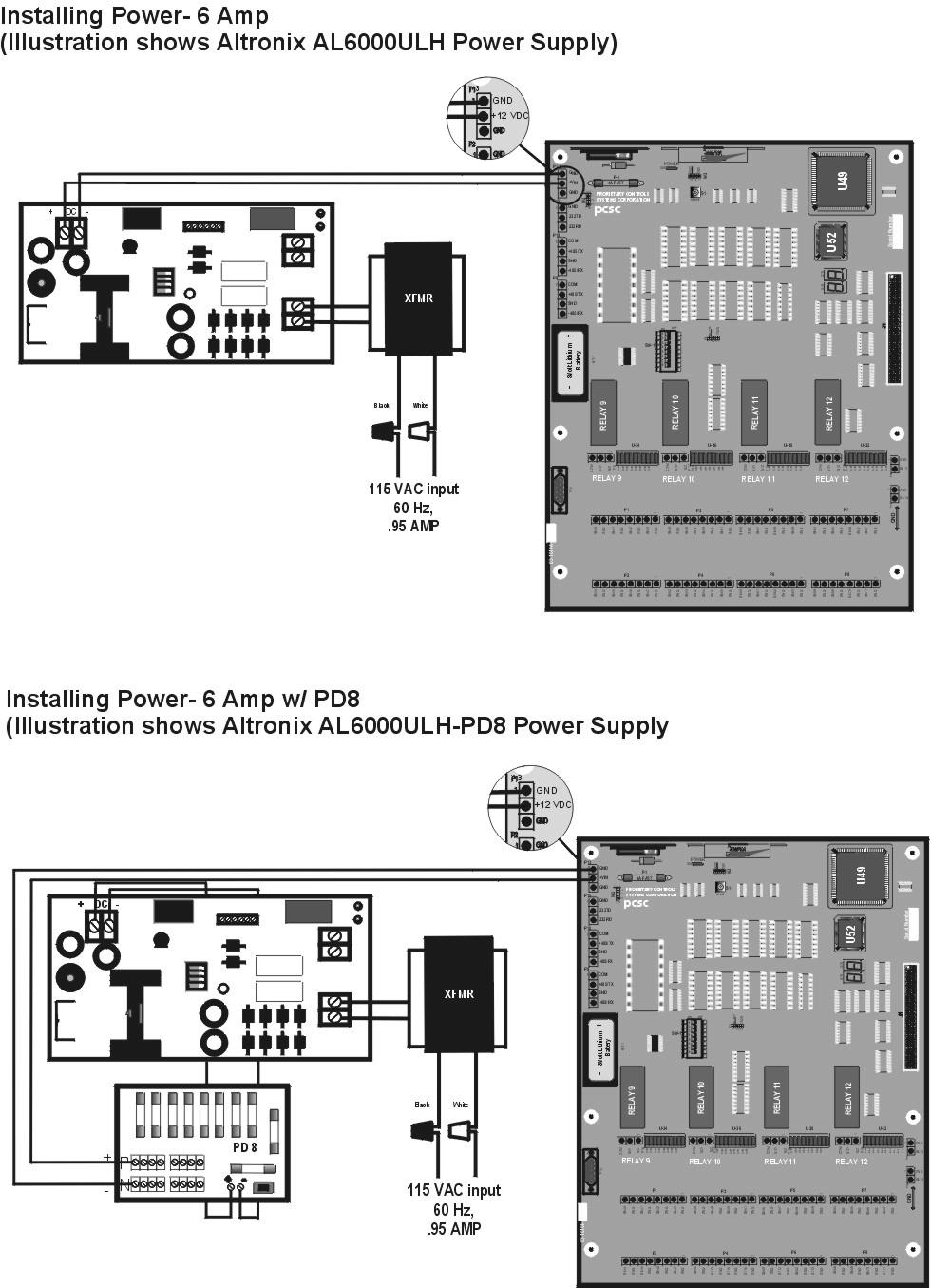
13 13
14 Resetting the SIM to Default Values In the event that the 3-volt lithium battery is removed or loses its electrical charge, the SIM must be reset. Follow the procedures below to restore the controller to the default values. A. With power on, move all switches at DIP switch SW1 to the right OFF (as printed on the circuit board). B. Press the Reset button at S1. C. The four 10-segment LED arrays (U34, U36, U30 and U32) will flash in waterfall effect and then stop. The Seven Segment LEDs (D78 and D79) will show 8.8. while the Reset process is underway. When the Reset process is complete, all four 10-segment LED arrays (U34, U36, U30, U32) will turn OFF, and the seven segment LEDs will show a single line segment flashing in a circular pattern clockwise. NOTE If any sense input is not wired during the Reset Process, its corresponding LED within the array (U34, U36, U30, or U32) will remain flashing (quickly). As the Sense Input will not calibrate, the calibration fault condition is therefore indicated by the blinking LED. D. Refer to page 28 and begin addressing the SIM by DIP switching the SIM (1-111). Set the communication protocol by following the instructions on page 32 [Setting MODEM or Direct Connect Configurations]. The system is now set to the default values. Refer to Quick Setup Steps on page 10 for page references. 14
15 Step 3- Wiring the Sense Inputs and Relays 15
16 Step 3 Properly Routing Your Cables Do not route data and power cables in the same conduit. Cross-talk and transmission of electrical noise may result. The SIM printed circuit board(s) will become damaged if the power cable grounds to the data cable. Grounding the Power and Data Lines Each cable has a set of drain lines that can be attached on the Host or controller end of the cable to any screws mounted in the optional enclosures. If other non-metallic enclosures are used for controller housing, ensure that an alternative source for earth grounding is available. If grounding locally is not possible, connect drain wires to provided ESD (Electro Static Discharge) hardware at the controller site (enclosure) or to earth grounded conduit. 16

17 Diagram of SIM Alarm Sense Grounding (Large and Small Cabinets) 17
18 Wiring the General Purpose Relays for Proper Mode of Operation Step 1. It is important to realize that when power is interrupted from the SIM that the General Purpose relays de-energize and continuity (conduction path) exists between the Common (Com.) and Normally Closed (N.C.) relay contacts. Should this loss-of-power situation arise, it must be determined whether the device(s) controlled by the SIM will become activated (or a Fail Safe environment), or de-activated (or a Fail Secure environment). Since the Driven Device can be a Door Lock, this possibility is now considered: Step 2. Refer to the two types of door hardware below and the circuit conditions that coincide with the state of the locks. Case A. Door Strike hardware requires continuity to unlock (for strikes that require power to lock, follow the outline given for maglocks). This is provided by a closed circuit condition (Normally Closed [N.C.]). Case B. Case C. Case D. Door Strike hardware does NOT require continuity to lock (for strikes that require power to lock, follow the outline given for maglocks). This is provided by an open circuit condition (Normally Open [N.O.]) Magnetic lock hardware requires continuity to lock. This is provided by a closed circuit condition (Normally Closed [N.C.]) Magnetic lock hardware does NOT require continuity to unlock. This is provided by an open circuit condition (Normally Open [N.O.]) Step 3. For Fail Safe operation, wire the appropriate door lock hardware to accommodate an unlocked condition upon interruption of SIM power. This is implemented by: For door strikes, wire between the Common and Normally Closed Door Relay contacts. For Magnetic Locks, wire between the Common and Normally Open Door Relay contacts. For Fail Secure operation, wire the appropriate door lock hardware to accommodate a locked condition upon interruption of SIM power. This is implemented by: For door strikes, wire between the Common and Normally Open Door Relay contacts. For Magnetic Locks, wire between the Common and Normally Closed Door Relay contacts. * For both conditions (Fail Safe and Fail Secure) it is presumed that Driven Device Power is battery backed up. Step 4. Program the quiescent (INACTIVE) state of the General Purpose output relay to provide a secured state. For Fail Safe environments, the quiescent state of the output relay should be ENERGIZED. For Fail Secure environments, it should be DE-ENERGIZED. Consult the LiNC-NET Administrator Manual (P/N: ) Door Overview/Hardware section for programming information. 18
19 Sense Input Status LEDs All 34 Supervised Sense Inputs are annunciated in the LED array U34, U36, U30 and U32. 19
 Blinks Twice/Second Trouble: Short (short circuit condition) Blinks Four-times/Second Calibration Fault (circuit isn t calibrated and")
20 LED Status Chart For All SIM Sense Inputs Constantly OFF Alarm Normal (secure condition) Constantly ON Circuit is in an alarm condition (violated condition) Blinks Once/Second Trouble: Open (Open circuit condition) Blinks Twice/Second Trouble: Short (short circuit condition) Blinks Four-times/Second Calibration Fault (circuit isn t calibrated and inoperative) 20
21 Wiring the Supervised Sense Inputs 21
")
22 Wiring the Supervised Sense Inputs (continued) 22

23 Installing Noise Suppression Devices To install either an MOV or diode (or both) to suppress noise and avoid problems related to spikes, follow the instructions below and refer to the diagrams on the following pages. Procedure: The most effective location for a suppression device is at the source; in this case, at the driven device. 1. Open the connection from the driven device and SIM Output Relay. 2. Install an MOV (Metal Oxide Varistor, ie.- Siemens S10K30 or equivalent) in parallel with the load. The MOV is a non-polarized device and will work with both AC and DC power. For further protection on DC units, a reverse biased diode may be installed (we suggest types 1N4004 to 1N4007 be used) also in parallel with the load. NOTE Use an additional MOV if you experience further noise at the driven device. 3. Note the wiring set-up of your particular system. Connections can be made either to the normally open (fail secure) contact or to the normally-closed (fail-safe) configuration whereby an isolation relay is used and a diode (or MOV) is added for noise suppression. 23
24 Step 4- Communicating with the SIM 24

25 Step 4- Communicating with the SIM Addressing the SIM Addressing an Individual SIM through the DIP Switch The SIM can communicate over a Dial-up MODEM, an RS232 or an RS485 serial direct connection. In a multidrop configuration, the SIM MUST communicate via RS-485 protocol. 1. You may elect to install the supervisory resistors at this time or optionally wait until after on-line communications has been established to the LiNC-NET Host PC. Set DIP switches 1-7 (located at SW1) to OFF position as etched on the SIM PCB. Press the Reset button at S1. This will calibrate all 34 of the supervised inputs on the SIM in addition to clearing all data from its memory. NOTE You must have ALL supervised switches in place for calibration. The supervised lines must be calibrated in order for the supervised inputs to work. If not, these sense inputs will be in constant fault when the calibration is performed. 2. Set the SIM ID number using the DIP switches at SW1. See DIP switching the SIM below. After setting the DIPswitches accordingly, press the S1 Reset Button. Addressing the panel does NOT affect the data stored in its memory nor does it affect the calibration of the Sense Inputs. 25
26 3. Establish communication for LiNC-NET (for 3.11/95/98 or NT). 4. Once all parameters and configurations are defined in LiNC-NET, download all files to the SIM and logoff LiNC-NET. This will cause a system Restart to occur on the SIM. The seven segment LEDs will show an 86 indicating the Restart taking place. 5. (Optional Step) To manually calibrate all supervised sense inputs on the SIM panel, place switches 1 through 7 to the ON position (as etched on the SIM PCB) and push the reset switch at S1. SW 1 ON OFF Calibration of the sense inputs does not affect the data stored in memory nor does it affect the panels addressing. 6. The SIM is ready for operation. 7. The ID number on the SIM should always remain set. In case of a power loss, the unit will read the switch for ID. Should the panel s ID number need to be changed the switches of SW1 should be set to reflect the new number and then the S1 Reset button should be pressed. This process will NOT erase any data from the SIM nor will it affect the calibration of the Sense Inputs. 26
27 DIP Switching the SIM Address (1-111) The DIPswitch (SW1) is located to the left center of the board. There are 8 switches. For the binary number of 1, flip a switch to the left. For zero (0), flip a switch to the right. SW1 On 1 Off Example: SIM #1 Switch# Switch# in Binary SW1 On 1 Off Example: SIM #23 Switch# Switch# in Binary NOTE Switch #8 is used to determine if the SIM communicates via either direct connect or dial-up communications. Switch #8 is only used to determine if the connection is Direct Connect or AutoDial. The ON/OFF designation is in reference to the labels printed on the SIM PCB. Not the switch itself! SIM Address in Decimal SW SIM Address in Decimal SW
28 SIM Address in Decimal SW SIM Address in Decimal SW SIM Address in Decimal SW NOTE AT SW1, switch #8 must remain in the ON position (left) for MODEM communication. 28
29 Setting MODEM or Direct Connect Configurations PCSC supports the US Robotics 33.6/56K Sportster model for MODEM communication. It is recommended that the MODEM be powered up via a U.P.S. To set up the SIM for MODEM communication, configure the DIPswitch settings at SW1, as follows: Example: MODEM connection (SIM, panel address is #1) SW1 On 1 Off Set # 1 to ON (left), 2 through 7 to OFF (right). Set # 8 to ON (left). Set the configuration and press the Reset button at S1. After the sequence of LEDs displays, set the SIM ID number (see DIP Switching the SIM Number). On the back of the US Robotics modem, locate the DIP switch. Set 1, 5 and 6 in the Up position and 2, 3, 4, 7 and 8 in the Down position. NOTE AT SW1, switch #8 must remain in the ON position (left) for MODEM communication. To set up the SIM for direct connect communication (default), configure the DIP switch settings at SW1, as follows: Example: Direct connection (SIM, Panel address is #1) SW1 On 1 Off Set # 1 to ON (left), 2 through 8 to OFF (right). Set the configuration and press the Reset button at S1. After the reset, set the SIM ID number (see DIP Switching the SIM Number). NOTE AT SW1, switch #8 must remain in the OFF position (right) for Direct Connect communication. To communicate from a SIM to the MODEM, two cables must be fabricated: one from the MODEM to the SIM and another for the PC host to the MODEM. See the diagrams under Cable Requirements. The ON/OFF designation is in reference to the labels printed on the SIM PCB. Not the switch itself! 29
30 Ensuring Proper Configuration of the MODEM To ensure that the MODEM retains the set configuration, the user should utilize HyperTerminal at the Host PC. The HyperTerminal program will set the configuration in the MODEM for constant uninterrupted use with the SIM. In the following procedure, the Init string will be written into the NOVRAM and therefore a power loss to the MODEM ONLY will not result in a continuous loop. Set switches 1, 5, 6, and 7 in the U.S Robotics Sportster MODEM (14.4K, 28.8, 33.6, or 56K) to Up. All other switches should be Down. Connect the MODEM to the PC using a standard PC to MODEM cable. From the PC (Win95/98/NT) access HyperTerminal by entering the following commands: 1. Click on Start, Programs, Accessories, and then, HyperTerminal. The Connection Description dialog box will now appear. 2. Type in a name for the connection (example: MODEM TEST). Click on a corresponding icon from the list. Click on the OK button. 3. The Connect To dialog box will now appear. The proper communications port used to communicate to the external MODEM is now selected within the Connect Using field (example: COM2). Click on the OK button. 4. The COM# Properties dialog box will now appear. Select 9600 in the bits per second field. Select 8 in the Data bits field, None in the Parity field, 1 in the Stop bits field, and Hardware in the Flow control field. Click on the OK button. The screen will now clear and the cursor will be at the top left corner of the HyperTerminal window. Type ATV1 E1 and press Enter. The MODEM will respond with OK. 5. Type ATI3 and press Enter to display the type of MODEM connected, followed by OK. 6. Type ATI4 and press Enter to display the MODEM s current settings, followed by OK. 7. Type ATI5 and press Enter to display the MODEM s NVRAM settings, including any stored telephone numbers, followed by OK. 8. Type ATEVQHSØ=1X&DØ and press Enter. The MODEM will respond by changing the A in the previous string to a Ø (zero). 9. Type AT&WØYØ and press Enter. No visual indication will be displayed as the MODEM was configured in the previous step to use Numeric Result Codes. 10. Type ATZ and press Enter. As in the previous step, no visual indication will be displayed. 11. Click on File, then Save, to save the configuration file. 12. Click on File, Exit, then Yes, to disconnect from the MODEM and exit HyperTerminal. 13. Power down the MODEM and turn switch 1, 5, 6, and 7 up. All others should be down. Connect the MODEM to the SIM. Perform functional testing. 30
31 MODEM Cabling- To communicate from a SIM to a MODEM, two cables must be fabricated: one from the MODEM to the SIM and another for the PC host to the MODEM. Cabling should be 22 AWG, 9- conductor, UL2576 and up to 6 feet in length. See the following diagrams. PC (DTE) 2 Modem (DCE) 6 ft. max. 1 Signal GND Signal GND RΙ DTR DCD DSR RTS CTS TXD RXD PC to Modem Cable, p/n pin female connector, DB-25 NOTE RΙ DTR DCD DSR RTS CTS RXD TXD 25-pin male connector, DB-25 1 DCE= Data Communications Equipment 2 DTE= Data Terminal Equipment SIM to Modem Cable, p/n Modem (DCE) 1 Rx Tx GND DSR DTR pin male connector, DB-25 6 ft. max. P TxD RxD Sig Gnd 3-pin terminal block connector 31
32 Setting the Baud Rate for Direct Connect Setting the Baud Rate for Direct 9600 bps SW 1 ON OFF Set switches as illustrated to the left at SW-1 and then push the Reset button S1. Then place the SW-1in position to represent the Communications Address of the panel. Push the Reset button S1. Panel is now ready to communicate to the LiNC-NET host at the new baud rate. Setting the Baud Rate for Direct 4800 bps Set switches as illustrated to the left at SW-1 and then push the Reset button S1. SW 1 ON OFF Then place the SW-1in position to represent the Communications Address of the panel. Push the Reset button S1. Panel is now ready to communicate to the LiNC-NET host at the new baud rate. Setting the Baud Rate for Direct 2400 bps SW 1 ON OFF Set switches as illustrated to the left at SW-1 and then push the Reset button S1. Then place the SW-1in position to represent the Communications Address of the panel. Push the Reset button S1. Panel is now ready to communicate to the LiNC-NET host at the new baud rate. Setting the Baud Rate for Direct 1200 bps SW 1 ON OFF Set switches as illustrated to the left at SW-1 and then push the Reset button S1. Then place the SW-1in position to represent the Communications Address of the panel. Push the Reset button S1. Panel is now ready to communicate to the LiNC-NET host at the new baud rate. 32
 setting for the Baud rate and press the S1 Reset button (Refer to the previous section) on page 35. 5.")
33 Changing the Baud Rate 1. Request the SIM Off-line in Define MicroLPM Online status screen in the LiNC-NET software. 2. Change the Baud rate in the Host computer Setup menu in the LiNC-NET Software. 3. Log off and back on to the system. 4. Set the switch (SW1) setting for the Baud rate and press the S1 Reset button (Refer to the previous section) on page Change the SW1 switch setting back to the SIM number. See section on DIP switching the SIM number on page Request the SIM back on-line in the Define Micro-LPM status screen in the LiNC-NET software. NOTE Presently the SIM only supports communication at 9600 BPS. SW1 DIPSwitch & S1 Reset button location 33

34 Direct Connecting with One SIM The PC Host is connected to the SIM by means of a cable designed for either RS-485 or RS-232 communication. The following diagrams illustrate the RS-485 and RS-232 DB9 or DB25 connectors options available. Wiring Diagram- SIM to PC, RS-485 Connector w/ DB25 connector w/ DB9 connector Com/GND +485/TX SHD -485/RX SIM to PC, RS-485 w/ DB25 Connector, Optically Isolated, PCSC P/N SIM, P Customer-fabricated cable may extend to 4,000ft. PC 1 Shield Gnd 7 Signal Gnd 2 TxA 3 RxA 4 RTS 5 CTS 14 TxB 16 RxB 25-pin female connector, DB-25 SIM to PC, RS-485 w/ DB9 Connector, Optically Isolated, PCSC P/N Com /Gnd +485/TX SHD -485/RX SIM, P Shield G d Signal Connect to PC earth ground Customer-fabricated cable may extend to 4,000ft. PC RD(A) TD(B) TD(A) RD(B) Sig Gnd 9-pin female connector, DB-9 34


35 Wiring Diagram- SIM to PC, RS-232 w/db25 connector Wiring Diagram- SIM to PC, RS-232 w/ DB9 Connector 35
36 Gnd 232TD/TX 232RD/RX SIM to PC Cable/ RS-232 w/ DB9 Connector, PCSC P/N SIM, P15 PC Customer-fabricated cable may extend to 25 ft DCD RxD TxD DTR Sig Gnd DSR RTS CTS RI 9-pin female connector, DB-9 SIM to PC Cable/ RS-232 w/ DB25 Connector, PCSC P/N SIM, P15 Gnd 1 232TD/TX 2 232RD/RX 3 Customer-fabricated cable may extend to 25 ft. PC DCD RxD TxD DTR Sig Gnd DSR CTS 25-pin female connector, DB-25 36
37 Communicating with Multiple SIMs (via RS-485) Once the PC host is connected to one SIM, the next SIM can be connected by wiring from P9 from the first SIM to P10 in the next SIM. This format can be repeated in up to 16 SIMs. In addition, any combination of MicroLPMs, IQ-200s and SIMs can be configured up to the 16 total limit on a single RS485 channel. The number of IQ/SIM/MicroLPM(s) within the entire LiNC-NET system is dependant on the LiNC-NET software version being used (consult the LiNC-NET Administrator Manual for additional information). See the next page for the SIM to MicroLPM to IQ-200 wiring connection. Wiring Diagram of Multiple SIMs 37

38 Wiring Diagram of Multiple SIMs, MicroLPMs, and IQs 38
39 Real Time Printing with the SIM To print from an SIM, a cable must be fabricated: a 9-pin female connector at the SIM-end to either a 9-pin or 25-pin male connector at the printer end. Cabling should be 22 AWG, 2-twisted pair, and up to 6 feet in length. See the following diagrams. The baud rate for the printer is 9600 bits per second at the SIM. Connect the SIM end of the cable to P14. SIM to Printer Cable DB-25 to DB-9, p/n RS232 Serial Printer Tx 2 Rx 3 RTS 4 GND 25-pin male connector, DB-25 6 ft. max. P Rx Tx CTS Sig. Gnd 9-pin female connector, DB-9 Cable configuration for capturing Real Time transactions to PC in HyperTerminal. SIM to PC/Laptop Cable DB-9 to DB-9, p/n PC/Laptop Tx 2 Rx 3 5 GND 9-pin female connector, DB-9 6 ft. max. P Rx Tx Sig. Gnd 9-pin female connector, DB-9 39

40 LANtronix Terminal Server Wiring Diagrams 40
41 Step 5- Status Lights and Dealing with Communication Errors 41

42 Status Lights The SIM circuit board has 7 LEDs. The status of an LED defines a certain activity or phase of a SIM function. Alarm sense status is also indicated by the LEDs. 42
43 Communication Errors Message at the PC SIM is not responsive What to Do Verify the following: 1. The red DC Power Indicator LED (D66) is ON. 2. Verify that the ID number corresponds to the SIM at the PC. (Check settings of switches at SW1). 3. Check cabling. (RS232/MODEM/RS485/Terminal Server). The seven-segment LEDs, D78 and D79, will indicate certain errors that can occur when processing cards. They also can communicate fatal errors that could occur. The following chart describes different error codes that are displayed by the seven-segment LEDs: LED Fatal Error Display Codes (Please CALL your PCSC representative): E1 ROM error detected- Probable PCB failure. E2 RAM error detected- Probable PCB failure. Verify that the IC at U8 is seated properly. E4 Packet addressing error- SIM failure E5 Packet queuing error- SIM failure E7 Terminal number configuration error- Readdress SIM EC Hardware configuration error- Improper panel model configuration in LiNC-NET ED Database invalid- RESET and configure SIM address EE Stray jump- Probable SIM PCB failure EF Execution of int vector- Probable SIM PCB failure 86 A system restart has occurred on the SIM panel 7F All sense inputs have been manually recalibrated 43

44 Communications Errors- Examples 44
45 SIM Point Definitions Designation SIM Point Definitions Location S13 P11, Pins 1, 2 S14 P12, Pins 1, 2 S40 P1, Pins 7, 8 S41 P1, Pins 5, 6 S42 P1, Pins 3, 4 S43 P1, Pins 1, 2 S44 P2, Pins 7, 8 S45 P2, Pins 5, 6 S46 P2, Pins 3, 4 S47 P2, Pins 1, 2 S48 P3, Pins 7, 8 S49 P3, Pins 5, 6 S50 P3, Pins 3, 4 S51 P3, Pins 1, 2 S52 P4, Pins 7, 8 S53 P4, Pins 5, 6 S54 P4, Pins 3, 4 S55 P4, Pins 1, 2 S56 P5, Pins 7, 8 S57 P5, Pins 5, 6 S58 P5, Pins 3, 4 S59 P5, Pins 1, 2 S60 P6, Pins 7, 8 S61 P6, Pins 5, 6 S62 P6, Pins 3, 4 S63 P6, Pins 1, 2 S64 P7, Pins 7, 8 S65 P7, Pins 5, 6 S66 P7, Pins 3, 4 S67 P7, Pins 1, 2 S68 P8, Pins 7, 8 S69 P8, Pins 5, 6 S70 P8, Pins 3, 4 S71 P8, Pins 1, 2 Outputs SIM Connector Common Normally Open Normally Closed CC9 P16 COM= Pin 3 N.O.= Pin 2 N.C.= Pin 1 CC10 P17 COM= Pin 3 N.O.= Pin 2 N.C.= Pin 1 CC11 P18 COM= Pin 3 N.O.= Pin 2 N.C.= Pin 1 CC12 P19 COM= Pin 3 N.O.= Pin 2 N.C.= Pin 1 45
46 Appendix- SIM Specifications 46
47 SIM Features Tamper 1 Supervised Sense Input (S13) Relay Output 4 Form C Dry Contact Outputs (cc# 9,10, 11, and 12) Rating is 2 Amps 24VDC Alarm Points 33 User-Defined Supervised Sense Inputs (S14, 40-71) Real-Time Clock Battery-backed clock/calendar Memory (Flash RAM) 128 KB (Standard) of Program Memory with capacity to expand to 256 KB Non-Volatile Data and Scratch Pad memory 512 KB (standard) of Battery-backed memory with capacity to expand to 1024 KB (1 MB) LED s 32 discrete LED s in four DIP Array packages for Alarm point status indication. 1 discrete LED for Power indication 2 seven-segment LED s for CPU error code Identification DIP Switch A single 8-station dipswitch is used for convenient panel addressing and communications mode (Direct Connect/ AutoDial) configuration Jumpers Three discrete 3-pins headers with shunt jumpers for setting the watchdog timer, A/D converter, and End of Line Termination. System Capacities Time Periods: 32 Holiday Time Periods: 32 Holiday List: 365 Days History Transactions: (4,000) 47
48 Spare Parts- SIM PCB Part Number Description Designation V Lithium Battery (no pins) BT A 250V 1/4 x 1/4, 3AG Fuse F pin Plug Connector P11, P pin Plug Connector* P1, P2, P3, P4, P5, P6, P7, P8 P9, P pin Plug Connector P13, P15, P16, P17, P18, P DPST Relay K1, K2, K3, K Jump Connector For W1 W3 * NOTE Plug P1, P2, P3, P4, P5, P5, P6, P7, P8 are 8-pin header connectors. Thus two 4-pin connectors are affixed to each of these 8-pin headers. 48
49 Cable Requirements and Maximum Lengths Communication- Type of Type of 22awg Maximum Distance Technology Stranded Wire SIM 2-pair, twisted, w/ To the last SIM overall shield 4,000 ft (1,219 m) 2-pair twisted and shielded cable recommended brands are: Belden 8728 Olympic 3030 Alpha 2404 or pair twisted and shielded cable recommended brands are: Belden 8777 Alpha 6010C WPW D431 NOTE All data communications cables must reside in a separate electrical conduit. Absolutely NO high voltage or AC power cables allowed within data conduits. 49
50 Tool Requirements- A small flat-blade screwdriver Wire-cutters/strippers Controller Specifications Microprocessor The SIM Controller is based on a 80C188EB microprocessor, operating at 16 MHz. The 80C188EB is a 16-bit processor (internal operation) with an eight-bit data bus. A 20-bit address bus provides a 1M Byte addressing range. Other features include three internal 16-bit timers, interrupt controller (8529 equivalent), multiple programmable chip select decoders with programmable wait states, and two serial communication channels. LEDs and DIPSwitches Four 10-segment LED arrays are provided which the microprocessor software can individually control. Eight general-purpose switches are provided for use by the microprocessor software, and are utilized for mode control, configuration setting, ID selection, etc. In addition, a Power ON LED is provided. Two Seven-Segment LED Display Error codes are displayed in Hexadecimal format. Refer to the error code section for listing of codes and their meanings. Real Time Clock A real time clock (DS1302) with battery backup is provided for time of day information. Relay Outputs Four Dry Contact Form C (socketed) outputs provide control of external devices Serial Communication - two serial communications ports are provided for the SIM controller- RS-485: Four wire (twisted pair) interface which is optically from the controller. A provision for installing a termination resistor is provided. RS-232: At P15 Direct connect/autodial-modem. At P14 (RS232 Serial Real Time standand RS232 interface. A DB9 connector with AT pinout is provided for an industry standard RS-232 interface. Power Supply The SIM controller requires +5VDC for all logic. Relays, output drivers, etc. require a +12 VDC supply. An on-board AC-DC converter accepts an external voltage source of 10-26VDC, and converts this unregulated source to the required +5VDC. For an input voltage range of volts, the +12VDC converts this voltage source to the required +12VDC 50
51 Battery Back-up Requirements A 12 AH battery is recommended as a back-up to the power supply, because it is the largest battery that will fit in the enclosure. The battery should be connected to the power supply charger in accordance with the manufacturer s instructions. Factory Settings At the factory the SIM is set as Panel #1, communications as direct connect 9600 baud, with 120 Ohm resistor termination disabled (W2 jumper set at 1-2). 51
52 End of Manual PCSC, Inc. July
-Series Intelligent Access Control Systems
 -Series Intelligent Access Control Systems IQ Series Installation Manual 33-10036-001 REV: G PCSC 3541 Challenger Street Torrance, CA 90503 Phone: (310) 638-0400 FAX: (310) 638-6204 www.1pcsc.com i First
Quick Start Installation Guide
 apc/l Quick Start Installation Guide Version A2 Document Part Number UM-201 May 2010 OVERVIEW The apc/l is an intelligent access control and alarm monitoring control panel which serves as a basic building
UC-2000 Installation Manual Unicorn Computers Technology Limited
 UC2000 Installation Manual Copyright 2003. All rights reserved. Table of Contents Specifications 2 Enclosure for the UC2000 Controller 3 Unicorn Access Control System Configuration 4 UC2000 Controller
PCL Port RS-232 Interface Card
 PCL-858 8-Port RS-232 Interface Card Copyright Notice This documentation and the software included with this product are copyrighted 2001 by Advantech Co., Ltd. All rights are reserved. Advantech Co.,
IQ-400 ELV - Elevator Control Module
 IQ-400 ELV - Elevator Control Module Installation Manual 33-10066-001 REV: A PCSC 3541 Challenger Street Torrance, CA 90503 Phone: (310) 303-3600 FAX: (310) 303-3600 Page 1 of 87 First Edition: March 2006
6222 Two Door Module Technical Operations Manual
 6222 Two Door Module Technical Operations Manual TABLE OF CONTENTS Specifications...3 Overview...4 Operations...5 Custom Access Mode...5 Standard Access Mode...5 Offline Access Mode...5 Offline Memory...5
Quick Start Installation Guide
 istar Pro Quick Start Installation Guide Version B0 Part Number UM-069 January 2005 OVERVIEW This guide defines all of the commonly used connection methods to the istar Pro. It outlines how to wire readers
ISOLATED RS-232 TO RS-422/485 CONVERTER
 QUICK START GUIDE ICD400A ISOLATED RS-232 TO RS-422/485 CONVERTER 24/7 TECHNICAL SUPPORT AT 877.877.2269 OR VISIT BLACKBOX.COM STEP 1 - Specifications Complies with FCC Class B and CE requirements. Withstands
Installation Guide Serial Interface T942SI
 Installation Guide 2003-02-8/ Ver. C Contents.... General... 2 Board Description... 2 3 Installation... 4 3. Mounting... 4 3.2 Opening the Housing... 4 3.3 Mounting together with other Units... 5 3.4 Wiring
ICD200A Quick Start Guide. Convert RS-232 data signals to RS-422/485 signals in heavy industrial areas.
 Industrial Opto-Isolated RS-232 to RS-422/485 Converter Convert RS-232 data signals to RS-422/485 signals in heavy industrial areas. Rugged IP30-rated metal case for panel mounting. Quick Start Guide Customer
Installation Guide of Hi-Speed USB to Industrial Single RS-422/485 Adapter
 Installation Guide of Hi-Speed USB to Industrial Single RS-422/485 Adapter Introduction of USB-COMi and USB-COMi-SI The USB-COMi and USB-COMi-SI Industrial Single RS-422/485 Adapters are designed to make
VertX. V100, V200 and V300. Installation Guide Barranca Parkway Irvine, CA USA. November Rev A.1
 15370 Barranca Parkway Irvine, CA 92618 USA VertX V100, V200 and V300 Installation Guide November 2011 6080-930 Rev A.1. Contents Introduction... 3 Parts List... 3 Product Specifications... 3 Cable Specifications...
Installation Guide of Hi-Speed USB to Octal RS-232/422/485 Adapter
 Installation Guide of Hi-Speed USB to Octal RS-232/422/485 Adapter Introduction The USB to Octal Serial Adapter is designed to make serial port expansion quick and simple. Connecting to a USB port on your
8 Port USB to RS- 232/422/485 Octal Adapter. Product Manual. Coolgear, Inc. Version 1.1 April 2018 Model Number: USB-8COMi-RM.
 8 Port USB to RS- 232/422/485 Octal Adapter Product Manual Coolgear, Inc. Version 1.1 April 2018 Model Number: USB-8COMi-RM 2 USB-8COMi-RM Product Manual Revision History Revision Date Author Comments
MEV Limited USB232/485 INSTRUCTION MANUAL
 MEV Limited USB232/485 INSTRUCTION MANUAL USB TO RS232 / RS485 SERIAL COMMUNICATIONS INTERFACE WITH ISOLATION OPTION Issue 5 LIST OF CONTENTS 1 INTRODUCTION 1 1.1 The Products Described in this Manual
ControlKeeper 4. General Information. Connecting Relay Loads. Installation Sheet. Getting Started. Power Supply Wiring. Mounting the Cabinet
 General Information ControlKeeper 4 Installation Sheet Model# CK4-120NO- Model# CK4-277NO The ControlKeeper-4 model is shipped in one package and is configured with either a 120V or a 277V transformer.
SmartLock Controller INSTALLATION MANUAL
 SmartLock Controller INSTALLATI MANUAL November 2015 Table of Contents INTRODUCTI... 3 Diodes... 4 Terminal Strips and Cable... 5 SPECIFICATIS... 6 SMARTLOCK CTROLLER LAYOUT... 8 LED Indicators... 9 Mounting...
W&T Manual Interface modules W&T
 Manual Subject to error and alteration Model 18801, 18811 18802, 18812 18803, 18813, 18833 18601, 18611 18602, 18612 18613, 18633 18401, 18411 18402, 18412 Release 1.7 43 09/2013 by Wiesemann und Theis
I/O Interface DNA300
 DNA300 OPERATIONS MANUAL 1 Ring Communications, Inc. Crisis Alert System I/O Interface DNA300 2 DNA300 OPERATIONS MANUAL 2006/06/13 DNA300 OPERATIONS MANUAL 3 Contents INTRODUCTION... 5 INSTALLATION...
SmartLock Pro INSTALLATION MANUAL
 SmartLock Pro INSTALLATI MANUAL July 2010 Cutting edge simplicity Table of Contents INTRODUCTI... 3 Diodes... 3 Power Supply Notice... 3 Terminal Strips and Cable... 4 SPECIFICATIS... 5 SMARTLOCK CTROLLER
3710 ACM 3750 PDC 3800 RTU. ISOCOM Communications Card Retrofit Instructions
 3710 ACM 3750 PDC 3800 RTU ISOCOM Communications Card Retrofit Instructions Danger During normal operation of this device, hazardous voltages are present which can cause severe injury or death. These
Introduction & Specifications of Hi-Speed USB to Serial Adapters
 Introduction & Specifications of Hi-Speed USB to Serial Adapters The USB Serial Adapters consist of the following models: USB Single Serial Adapter (ES-U-1001, ES-U-1001-A) USB Single Serial Adapter (ES-U-1001-M,
Installation Guide of Hi-Speed USB-to-Optically Isolated RS-422/485 Adapter
 Installation Guide of Hi-Speed USB-to-Optically Isolated RS-422/485 Adapter Introduction of ES-U-2101-M The USB-to-Optically Isolated RS-422/485 Adapter is designed to make industrial communication port
DATA CONNECT ENTERPRISE
 DATA CONNECT ENTERPRISE User s Manual IG202T and IGV23 Modem Document Number 520-01005-001 Rev. A DATA CONNECT Contents Contents... iii Figures... iv Chapter 1 Introduction... 5 Features...6 Applications...7
Quick Start Installation Guide
 RM-DCM-2 Quick Start Installation Guide Version G0 Document Part Number UM-215 May 2010 OVERVIEW The RM-DCM-2 is a UL294 Listed and UL1076 Listed door control module that includes the RM-4E Reader Module
Introduction & Specifications of Hi-Speed USB to Industrial Dual Ports RS-422/485 Adapter
 Introduction & Specifications of Hi-Speed USB to Industrial Dual Ports RS-422/485 Adapter USB to Dual RS-422/485 Adapter (USB-2COMi-M) USB to Dual Opto-isolated RS-422/485 Adapter (USB-2COMi-SI-M) - with
3.1 I-7560 Pin Assignment and Specifications: Introduction
 3.1 I-7560 Pin Assignment and Specifications: Introduction The I-7560 adds a Windows serial Com port via its USB connection and is compatible with new & legacy RS-232 devices. USB Plug and Play allows
Installation Guide of Hi-Speed USB to Industrial I/O Adapter
 Installation Guide of Hi-Speed USB to Industrial I/O Adapter Introduction of USB-COMi-SI-M The USB Industrial I/O Adapter is designed to make industrial communication port expansion quick and simple. Connecting
Two Door Controller GEN-045
 Australian Owned, Designed and Manufactured Two Door Controller GEN-045 Genesis Electronics Australia Pty Ltd www.genesiselectronics.com.au Distributed by: Genesis reserves the right to change or modify
Manual Industry Interfaces
 Manual Industry Interfaces W&T Release. Type 0, 0 0, 00 0, 0 0, 0 Industry Interfaces 0/0 by Wiesemann & Theis GmbH Subject to errors and changes: Since we can make mistakes, none of our statements should
istar Pro Installation Guide
 istar Pro Installation Guide UM-241 Version A1 October 2010 istar Pro Installation Quick Start Guide System Components The istar Pro hardware components consist of: General Controller Module (GCM) A general
Intelligent Devices IDI 1100 Series Technical Manual
 Intelligent Devices IDI 1100 Series 4411 Suwanee Dam Road, Suite 510 Suwanee, GA 30024 T: (770) 831-3370 support@intelligentdevicesinc.com Copyright 2011, Intelligent Devices, Inc. All Rights Reserved
ICD105A 1008 page 1/ r001 ICD105A. Industrial RS-232 to RS-422/485 Converter
 ICD105A 1008 page 1/5 7319 r001 ICD105A Industrial RS-232 to RS-422/485 Converter Data Rates up to 115.2 Kbps 10 48 VDC Input Power Range Wide Operating Temperature 3-Way 2000V Optical Isolation Modbus
Cardax FT Controller 3000
 Installation Note Cardax FT Controller 000 CAUTION This equipment contains components that can be damaged by electrostatic discharge. Ensure both you and the equipment are earthed before beginning any
2001 by NEC America. All Rights Reserved. Printed in U.S.A.
 These instructions are customized for the CNet Modem V.90 k bps modem (P/N D) contained in the i Modem Kit P/N 9, i Modem Kit P/N 90B, and the i and 0i Modem Kit P/N 9. The modem connected to the system
genesis TECHNICAL MANUAL Two-Door Controller GEN-045
 Two-Door Controller GEN-045 Genesis Electronics Australia Pty Ltd www.genesiselectronics.com.au info@genesiselectronics.com.au Australian Owned, Designed and Manufactured Distributed By:- Genesis reserves
IQX and NRX Series Intelligent Access Control Systems IQX and NRX Series Installation Manual REV: D
 IQX and NRX Series Intelligent Access Control Systems IQX and NRX Series Installation Manual 33-10039-001 REV: D PCSC 3541 Challenger Street Torrance, CA 90503 Phone: (310) 638-0400 FAX: (310) 638-6204
Product Manual. 2 Port USB to RS-422 /485 Optical Isolated Adapter. Coolgear, Inc. Version 1.1 March 2018 Model Number: USB-2COMi-Si-M
 2 Port USB to RS-422 /485 Optical Isolated Adapter Product Manual Coolgear, Inc. Version 1.1 March 2018 Model Number: USB-2COMi-Si-M 2 USB-2COMi-Si-M Product Manual Revision History Revision Date Author
Rev. A. ANC Series RS-485/RS-422 Synchronous Clock Display. Antona Corporation (818) URL:
 URL:") Rev. A ANC - 7020 Series RS-485/RS-422 Synchronous Clock Display Antona Corporation, Los Angeles, CA Antona Corporation (818)783-4299 URL:http://www.antona.com 1 Antona Corporation Copyright Copyright
Rev. A ANC - 7020 Series RS-485/RS-422 Synchronous Clock Display Antona Corporation, Los Angeles, CA Antona Corporation (818)783-4299 URL:http://www.antona.com 1 Antona Corporation Copyright Copyright
Moxa TCC-100 Series User s Guide
 Moxa TCC-100 Series User s Guide Eighth Edition, February 2009 www.moxa.com/product 2009 Moxa Inc. All rights reserved. Reproduction without permission is prohibited. Moxa TCC-100 Series User s Guide The
PXL-250 Tiger Controller
 PXL-0 Tiger Controller This quick start guide is made up of specification sheets, a DO/DON T list, basic installation drawings, first time power-on instructions, and short descriptions of key terms and
EasySYNC Ltd. USB to Serial Converters Manual
 EasySYNC Ltd Document Reference No.: ES_000061 Issue Date: 2011-08-23 The ES-U-xxxx-x adapters are a series of USB Serial Converters from EasySYNC Ltd. They provide a simple method of adapting legacy RS-232
Product Manual. Single Port RS-232 USB Serial Adapter Optical- ISO Surge Protection. Coolgear, Inc. Version 1.1 March 2018 Model Number: USB-COM-Si-M
 Single Port RS-232 USB Serial Adapter Optical- ISO Surge Protection Product Manual Coolgear, Inc. Version 1.1 March 2018 Model Number: USB-COM-Si-M 2 USB-COM-Si-M Product Manual Revision History Revision
Product Manual. USB to Optical Adapter Industrial Isolated RS- 232/422/485. Coolgear, Inc. Version 2.1 December 2018 Model Number: USB-COMi-Si-M
 USB to Optical Adapter Industrial Isolated RS- 232/422/485 Product Manual Coolgear, Inc. Version 2.1 December 2018 Model Number: USB-COMi-Si-M 2 USB-COMi-SI-M Product Manual Revision History Revision Date
STAR Comm Modem Kit for the Micro/PX-2000: Setup Instructions
 STAR Comm Modem Kit for the Micro/PX-2000: Setup Instructions This STAR Comm Modem Kit was designed specifically for use with the Micro/PX-2000 micro. The STAR Comm Modem is an external modem that can
AD-8923-BCD. Remote Controller (BCD) INSTRUCTION MANUAL 1WMPD
 INSTRUCTION MANUAL 1WMPD") AD-8923-BCD Remote Controller (BCD) INSTRUCTION MANUAL 1WMPD4002137 2010 A&D Company, Limited. All rights reserved. No part of this publication may be reproduced, transmitted, transcribed, or translated
AD-8923-BCD Remote Controller (BCD) INSTRUCTION MANUAL 1WMPD4002137 2010 A&D Company, Limited. All rights reserved. No part of this publication may be reproduced, transmitted, transcribed, or translated
CA-A480-A Elevator Controller. Reference & Installation Manual
 CA-A480-A Elevator Controller Reference & Installation Manual TABLE OF CONTENTS INTRODUCTION.................................................................. 4 Introduction.............................................................................................
Sender Receiver Sender
 EEE 410 Microprocessors I Spring 04/05 Lecture Notes # 19 Outline of the Lecture Interfacing the Serial Port Basics of Serial Communication Asynchronous Data Communication and Data Framing RS232 and other
OnRISC. OnRISC Baltos ir 2110
 OnRISC OnRISC Baltos ir 2110 Hardware Manual Edition: October 2015 Tel: +49 40 528 401 0 Fax: +49 40 528 401 99 Web: www.visionsystems.de Support: service@visionsystems.de The software described in this
CDN502 HIGH DENSITY I/O ADAPTER USER GUIDE
 CDN502 HIGH DENSITY I/O ADAPTER USER GUIDE 13050201 (c) Copyright DIP Inc., 1996 DIP Inc. P.O. Box 9550 MORENO VALLEY, CA 92303 714-924-1730 CONTENTS DN502 PRODUCT OVERVIEW 1 DN502 INSTALLATION 1 POWER
Bluetooth to RS-232&RS422/485. EX-9132B/BI Bluetooth Adapter Operation Manual
 Bluetooth to RS-232&RS422/485 EX-9132B/BI Bluetooth Adapter Operation Manual First Edition, Jun 2008 Table of Contents 1. Introduction 2 2. Package checklist 3 3. Product Specification 4 4. Product Panel
485DRCI. Industrial RS-232 to RS-422/485 Converter B&B ELECTRONICS PRODUCT INFORMATION. Specifications Serial Technology
 485DRCI RS-232 RS-485 2-Wrie RS-422/485 4-Wire RS-232 CON. RS-422/485 CON. Data Rate Isolation Surge Protection Industrial Bus Source Input Voltage Power Consumption Connector p/n 7207r3 485DRCI-4108ds
RCS/6000. Hardware. Manual
 RCS/6000 Hardware Manual Document number 80-001052-6 Revision A RCS/6000 Hardware Manual Document part number 80-001052-6 Revision History Date Revision Description 4/10/01 A Initial production release
Korenix JetCard Series Multiport Serial Card/Ethernet Switch Card User s Manual
 Korenix JetCard Series Multiport Serial Card/Ethernet Switch Card User s Manual Third Edition, Dec. 2008 www.korenix.com Korenix JetCard Series Multiport Serial Card/Ethernet Switch Card User s Manual
CDN503 HIGH DENSITY I/O ADAPTER USER GUIDE
 CDN503 HIGH DENSITY I/O ADAPTER USER GUIDE 13050301 (c) Copyright DIP Inc., 1996 DIP Inc. P.O. Box 9550 MORENO VALLEY, CA 92303 714-924-1730 CONTENTS DN503 PRODUCT OVERVIEW 1 DN503 INSTALLATION 1 POWER
ANC Series RS-422 Serial Communications Adapter
 Rev. B $ 5.00 ANC - 6000 Series RS-422 Serial Communications Adapter Antona Corporation, Los Angeles, CA Antona Corporation (818)783-4299 FAX (818)783-4216 1 Antona Corporation Copyright Copyright (c)
General Operating, Maintenance and Installation Manual
 General Operating, Maintenance and Installation Manual Hardware Platform for Protocol Converter Small Embedded Controller - SEC2-91056 Erlangen Telephone +49 9131 92076-0 Fax: +49 9131 92076-10 Internet:
Fault Tolerant Intelligent Access Control System Installation Manual REV: B
 Fault Tolerant Intelligent Access Control System Installation Manual 33-10068-001 REV: B PCSC 3541 Challenger Street Torrance, CA 90503 Phone: (310) 303-3600 FAX: (310) 303-3600 www.1pcsc.com First Edition:
NetworX Series. NX-507E RELAY EXPANDER NX-508E OUTPUT EXPANDER Installation and Startup
 NetworX Series NX-0E RELAY EXPANDER NX-0E OUTPUT EXPANDER Installation and Startup NX-0E / NX-0E AUXILIARY MODULES TABLE OF CONTENTS I. GENERAL DESCRIPTION... II. WIRING INFORMATION... III. NX-0E TERMINAL
FCC Information. RoHS This product is RoHS compliant. SJ/T The following contains information that relates to China.
 FCC Information This equipment has been tested and found to comply with the limits for a Class B digital device, pursuant to Part 15 of the FCC Rules. These limits are designed to provide reasonable protection
TruPortal Dual Door Interface Module Quick Reference
 TruPortal Dual Door Interface Module Quick Reference en-us Packing List Introduction The TruPortal Dual Door Interface Module (TP-ADD-2D) can support two complete door configurations, with up to two readers
EasySYNC Ltd. USB to Serial Converters Manual
 EasySYNC Ltd Document Reference No.: ES_000061 Issue Date: 2011-01-26 The ES-U-xxxx-x adapters are a series of USB Serial Converters from EasySYNC Ltd. They provide a simple method of adapting legacy RS-232
Manual Fiber Optic Interfaces
 Manual Fiber Optic Interfaces Type 81210, 81211 61210, 61211 65210, 65211 41210 Release 1.4 Subject to error and alteration 31 06/2007 by Wiesemann & Theis GmbH Subject to error and alteration: Since it
PCL-741 Isolated Dual Port RS-232/Current-Loop Interface Card
 PCL-741 Isolated Dual Port RS-232/Current-Loop Interface Card Copyright Notice This documentation and the software included with this product are copyrighted 2001 by Advantech Co., Ltd. All rights are
ZM56 High-Speed Industrial Modem. Command Summary. 1 ZM56 High-Speed Industrial Modem
 ZM56 High-Speed Industrial Modem Command Summary 1 ZM56 High-Speed Industrial Modem AT Command Summary Command AT ATA ATDT ATE0 ATE1 ATH ATH1 ATI ATO ATS Description Attention Prefix Precedes all commands
NetworX Series. NX-507E RELAY EXPANDER NX-508E OUTPUT EXPANDER Installation and Startup
 NetworX Series NX-0E RELAY EXPANDER NX-0E OUTPUT EXPANDER Installation and Startup NX-0E / NX-0E AUXILIARY MODULES TABLE OF CONTENTS I. GENERAL DESCRIPTION... II. WIRING INFORMATION... III. NX-0E TERMINAL
ES-362U PRESETTABLE MASTER TIMER
 142 SIERRA ST., EL SEGUNDO, CA 90245 USA (310)322-2136 FAX (310)322-8127 www.ese-web.com ES-362U PRESETTABLE MASTER TIMER OPERATION AND MAINTENANCE MANUAL The ES-362U is a four digit, presettable 100 minute
ADAM-4510 RS-422/RS-485 Repeater ADAM-4510S Isolated RS-422/485 Repeater ADAM-4520 Isolated RS-422/485 Converter Startup Manual
 ADAM-510 RS-/RS-85 Repeater ADAM-510S Isolated RS-/85 Repeater ADAM-50 Isolated RS-/85 Converter Startup Manual Packing List Before you begin installing your module, please make sure that the following
INSTALLATION MANUAL. Gateway EKBMSMBA EKBMSBNA
 INSTALLATION MANUAL EKBMSMBA EKBMSBNA Serial module BMS print out line alarm alarm 2 rx tx reset µchiller compact EKBMSMBA EKBMSBNA Installation manual READ THIS MANUAL ATTENTIVELY BEFORE STARTING UP THE
Serial Link Generic Tank Mode Installation Manual. Pro Fuel Management System. RE Rev C July 00
 Serial Link Generic Tank Mode Installation Manual Pro Fuel Management System RE260-337 Rev C July 00 Serial Link Generic Tank Mode Installation Manual RE260-337 Rev C July 00 Certifications and Listings
This 4-port RS-422/485 Adapter is provided with an external switching power adapter in the package.
 USB-4COMi-M USB to Quad RS-422/485 to Serial Adapter Manual The USB to Industrial Quad RS-422/485 Adapter is designed to make industrial communication port expansion quick and simple. Connecting to a USB
Suprex RS-485 SPX-7500 Wired Reader-Extender
 Suprex RS-485 SPX-7500 Wired Reader-Extender Product Manual SPX-7500_MAN_181206 Cypress Integration Solutions 35 Years of Access Control Ingenuity CypressIntegration.com 2018 Cypress Computer Systems 1778
Storage/Control I/O Module
 CHAPTER 4 The performs two functions: to connect outside interfaces to the system controller and to house the hard disk drive. It plugs into the back of the VCO/4K system and provides the I/O interfaces
DGH A3000 Configuration Guide For use with DGH Modules
 DGH A3000 Configuration Guide For use with DGH Modules Revision Date: 12/07/05 Version: 1.00 Contact Information: http://www.dghcorp.com Ph: (603) 622-0452 Fax: (603) 622-0487 Mailing Address: DGH Corporation
System Galaxy Hardware Manual
 System Galaxy Hardware Manual Version 2.4 June 19, 2004 System Galaxy Hardware Manual 1 Information in this document is subject to change without notice. No part of this document may be reproduced, copied,
USB-16COMi-M 16-Port RS-422/485 USB Serial Adapter User Manual. Features and Specifications. Power Supply
 USB-16COMi-M 16-Port RS-422/485 USB Serial Adapter User Manual The USB to industrial 16-Port RS-422/485 Adapter is designed to make serial port expansion quick and simple. Connecting to a USB port on your
Moxa TCC-100 Series Hardware Installation Guide
 Moxa TCC-100 Series Hardware Installation Guide Twelfth Edition, January 2015 www.moxa.com/product 2015 Moxa Inc. All rights reserved. P/N: 1802001000319 Moxa TCC-100 Series Hardware Installation Guide
Installation Instructions for the AUTOcard-SA System
 Installation Instructions for the AUTOcard-SA System IMPORTANT NOTICE The AUTOcard-SA system is a very reliable and easy to use system. However, damage could occur if it is installed incorrectly. In particular,
Enhanced Mini-Chansim Model VCS-232
 Enhanced Mini-Chansim Model VCS-232 Operations Manual ViaSat Inc. 6155 El Camino Real Carlsbad, CA 92009 http://www.viasat.com SAFETY WARNING Always observe standard safety precautions during installation,
I-7560U/7561U/7563U. User Manual WARRANTY WARNING COPYRIGHT TRADEMARKS CONTACT US
 I-7560U/7561U/7563U User Manual USB tto RS--232//422//485 Converrtterrss Verr.. 1..0,, Decc.. 2013 WARRANTY All products manufactured by ICP DAS are warranted against defective materials for a period of
Introduction. General Ratings
 Introduction Storage temperature Operating temperature Humidity Weight Dimensions Screw terminal wire gauge Supply voltage Supply currents Maximum baud rate Unit Mounting Housing o -20 to +70 C o Allows
IQ Series Architect/Engineer Guide Specification P/N Revision 5.0
 IQ Series Architect/Engineer Guide Specification P/N 37-20002-001 Revision 5.0 PCSC 3541 Challenger St. Torrance, California 90503 Phone/Fax: (310) 303-3600 Web Site: http://www.1pcsc.com E-Mail: Sales@1PCSC.COM
ZM24x Quick-Connect Industrial Modem. User s Manual
 ZM24x Quick-Connect Industrial Modem User s Manual Version 1.1 2004 ZYPEX, Inc. All Rights Reserved 1 ZM24x Quick-Connect Industrial Modem Since the equipment explained in this manual has a variety of
Installing the DX LCD Display
 DX LCD Display User s Guide 3-1 Chapter 3 Installing the DX LCD Display Introduction Use the DX LCD Display as either a portable device, or permanently mount it in a panel or on the wall. For panel and
USB to RS-232/RS422/485. US-101-I USB To Serial Operation Manual
 USB to RS-232/RS422/485 US-101-I USB To Serial Operation Manual First Edition, Jun 2008 Table of Contents 1. Introduction 2 2. Package checklist 3 3. Product Specification 4 4. Product Panel Views Description
Research Concepts RC2500 Antenna Interface Unit (AIU) Board Set
 Board Set") Research Concepts RC2500 Antenna Interface Unit (AIU) Board Set A board set has been developed that can be incorporated into an AIU for an RC2500 antenna controller. This board set is the basis of RC2500
Research Concepts RC2500 Antenna Interface Unit (AIU) Board Set A board set has been developed that can be incorporated into an AIU for an RC2500 antenna controller. This board set is the basis of RC2500
RS-232 Driver Module
 RS-232 Driver Module Low Cost TTL to RS-232 Adapter DCE (SKU #30000) DTE (SKU #30010) Transmit and receive RS-232 Data Can be mounted on any solderless breadboard, or hard-wired Reconfigurable for DCE
JetBox 9300/9310 User Manual. Hardware
 JetBox 9300/9310 User Manual Hardware www.korenix.com 0.0.6 Copyright Notice Copyright 2008 Korenix Technology Co., Ltd. All rights reserved. Reproduction without permission is prohibited. Information
Digital Lighting Systems, Inc.
 Digital Lighting Systems, Inc. Four Channel Dry Contacts Relays Switch Pack DMX512 compatible USER'S MANUAL -UM User's Manual - Page 1 GENERAL DESCRIPTION The is a 4-channel DMX-512 compatible electro-mechanical
MODEL DSU Kbps Rack Mount CSU/DSU OPERATOR S MANUAL. 280 I-80 West Exit 1 PO Box 1330 Verdi NV 89439
 MODEL DSU-56 56 Kbps Rack Mount CSU/DSU OPERATOR S MANUAL 280 I-80 West Exit 1 PO Box 1330 Verdi NV 89439 TEL: 775-345-8000 FAX: 775-345-8010 E-MAIL: SUPPORT @S.NET DSU-56 Rack Mount TABLE OF CONTENTS
USB-COMi-TB USB to Industrial Single RS-422 / 485 Adapter Manual. Specifications and Features
 USB-COMi-TB USB to Industrial Single RS-422 / 485 Adapter Manual The USB-COMi-TB USB-to-Industrial Single RS-422/485 Adapter is designed to make industrial communication port expansion quick and simple.
Contents INTRODUCTION...1 CARD SETUP...2 INSTALLATION TECHNICAL DESCRIPTION SPECIFICATIONS... 14
 Contents INTRODUCTION...1 OVERVIEW...1 WHAT S INCLUDED...1 FACTORY DEFAULT SETTINGS...1 CARD SETUP...2 ADDRESS SELECTION...2 IRQ SELECTION...3 INTERRUPT MODES...4 RS-485 ENABLE MODES...5 CONNECTOR PIN
The Analyst. RS422/RS232 Tester. (Standard Model) User Manual
 User Manual") 12843 Foothill Blvd., Suite D Sylmar, CA 91342 818 898 3380 voice 818 898 3360 fax www.dnfcontrolscom The Analyst RS422/RS232 Tester (Standard Model) User Manual Manual Revision 102506 Table of Contents
12843 Foothill Blvd., Suite D Sylmar, CA 91342 818 898 3380 voice 818 898 3360 fax www.dnfcontrolscom The Analyst RS422/RS232 Tester (Standard Model) User Manual Manual Revision 102506 Table of Contents
OPERATIONS MANUAL. n.form I/O Expander (RACK MOUNT) Document Number: Rev B
 Document Number: Rev B") OPERATIONS MANUAL n.form I/O Expander (RACK MOUNT) Document Number: 200-0009 Rev B table of contents INTRODUCTION FEATURES & CAPABILITIES 1 WIRING General I/O Configuring The System Using The System 4
OPERATIONS MANUAL n.form I/O Expander (RACK MOUNT) Document Number: 200-0009 Rev B table of contents INTRODUCTION FEATURES & CAPABILITIES 1 WIRING General I/O Configuring The System Using The System 4
Installation Manual GENERAL DESCRIPTION...2 WIRING INFORMATION FOR NX-507 AND NX NX-507 TERMINAL DESCRIPTION...3 NX-507 DRAWING...
 NX-0 RELAY EXPANDER NX-0 OUTPUT EXPANDER Installation Manual GENERAL DESCRIPTION... WIRING INFORMATION FOR NX-0 AND NX-0... NX-0 TERMINAL DESCRIPTION... NX-0 DRAWING... NX-0 TERMINAL DESCRIPTION... NX-0
F7_F707_F708 Installation Instruction V1.0 F7_F707_F708. Access Control Terminal. Installation Instructions
 F7_F707_F708 Access Control Terminal Installation Instructions Revised May 2008 About this Guide This guide provides installation instructions only. For information regarding actual operation and configuration
Energy Management System. Operation and Installation Manual
 Energy Management System Operation and Installation Manual AA Portable Power Corp 825 S 19 TH Street, Richmond, CA 94804 www.batteryspace.com Table of Contents 1 Introduction 3 2. Packing List 5 3. Specifications
Brief Instruction. 4.2 ISDN devices. 4.2 GSM devices MDH 502 MDH 536 MDH 506 MDH 512 MDH 542 MDH 522
 4.2 ISDN devices 502 506 512 522 532 536 542 552 556 Voltage VDC 24 Current ma (24V) 60 60 70 90 90 100 80 100 110 Protection class (IP) 20 Range of use Dry Surroundings Temperatures (Plant) 0 50 C Temperatures
F2MC MB90385 series Evaluation Board Documentation. Revision Date Comment V New document
 F2MC MB90385 series Evaluation Board Documentation Revision Date Comment V1.0 08.25.02 New document 1 Warranty and Disclaimer To the maximum extent permitted by applicable law, Fujitsu Microelectronics
Card Descriptions and Wiring Manual. Load Computer 1010 CJ
 Card Descriptions and Wiring Manual Load Computer CJ Table of Contents CHAPTER 1 Card Descriptions and Terminal Layouts 1.1 CPU Card - S10CPU-xxx-I3..................................... 1-2 1.1.1 Card