CoventorWare Tutorial. Presented by Brian Pepin 11/07/2011
|
|
|
- Delphia Anthony
- 6 years ago
- Views:
Transcription
1 CoventorWare Tutorial Presented by Brian Pepin 11/07/2011
2 Downloading Software CoventorWare 2010 Full Release available at Click on link to download CoventorWare 2010 for Windows XP Pro and Windows 7 (873 MB) Username: ucberk3 Password: sensor Release for Red Hat Linux also available Do NOT download SABER component library After downloading, click on.exe file to begin installation (just follow along with the menus) May take a very long time (>30 minutes) be PATIENT! When the program asks for license file at the end of the installation, just press cancel Restart computer when finished (even though not prompted)

3 Licensing After opening CoventorWare for the first time, you will be prompted to enter license info Change all licenses as shown below
4 Tutorial To learn most useful aspects of CoventorWare, only need to complete first two tutorial sections (2-4 hours) memsdesign_vol1.pdf; Section 1 (Introduction) and Section 2: Beam Design Other sections of interest Section 3 (extraction of lumped elements from FEM models); Section 9 (Resonator Analysis); Section 9 (Thermal Analysis)

5 Overview Motivation Why Coventor? Coventor Simulation Flow Designer Material Properties Editor Process Editor Layout Editor Analyzer Meshing MemElectro MemMech CoSolve Parametric Simulations Visualization Advanced Solvers and Reduced Order Modeling Starting to use Coventor
 Coupled thermomechanical (ex. Thermoelastic damping, thermal stability) Piezoelectric effects (ex.")
6 Motivation Why Coventor? Intuitive for MEMS engineer 3D model construction from GDSII files Streamlined operation for common MEMS simulations, including: Coupled electromechanical (ex. Pull-in, electrostatic spring softening) Coupled thermomechanical (ex. Thermoelastic damping, thermal stability) Piezoelectric effects (ex. Stress stiffening) In addition to modal and harmonic analyses, capable of transient simulation with nonlinear boundary conditions (i.e. contact) Straightforward addition of damping to any simulation (stokes or squeeze film air damping, anchor loss, themoelastic, etc.) Powerful visualization tools Coupling with ODE models
7 Coventor Simulation Flow Designer Analyzer Inputs: - Materials Data - Process Data - Layout (GDSII or Manual) Inputs: - 3D Model from Designer - Meshing Info - Analysis Definition Output: - 3D Model Output: - Simulation Results


8 Designer - Overview Materials & Process GDSII Layout Files 3D Model
 Piezoresistive")
9 Designer - Materials Database of >40 commonly used MEMS materials, or can define custom materials Young s Modulus and Poisson Ratio Residual stress distribution and magnitude Electrical conductivity (constant, exponential, look-up table, diffusion limited) Piezoresistive properties
 Includes idealized modeling actions as well as common MEMS process steps and sequences")
10 Designer Process Editor Model is defined using actual process steps, coupled with masking layers Can define nonidealities such as sidewall angles Supports different types of material depositions (i.e. conformal shell, planar fill and stack material) Includes idealized modeling actions as well as common MEMS process steps and sequences

11 Designer Layout Editor Can import GDSII layout files or draw layout in Coventor using drawing toolset Layer names transfer directly from Cadencegenerated GDSII files Drawing toolset supports drawing of true curves better for meshing


12 Importing GDSII Files 1. Open a new layout in Layout Editor 2. From the file menu click open, making sure that you have GDSII selected as the file type. Open a GDSII file for single die (any larger will crash the computer) 3. When prompted to select a template file, press cancel 2. Select the structure of interest using the Select Area feature from the Edit menu 3. Select Copy from the Edit menu, and open a new layout in the Layout Editor. This will automatically be a.cat file 4. Select Paste from the Edit Menu. Your Top Cell name should be the same as your.cat file name

 Best practice is to build up your model one process step at a time, checking in the Preprocessor for abnormalities after each")
13 Designer - Preprocessor Can select and name faces, volumes, and conductors Several faces can be selected at once to define a continuous surface Give as many features as possible unique, descriptive names only named features can be BC s! Quality Query of Solid Model Check for sliver faces and small edges Heal function can repair some problems Try using planar fill instead of conformal shell to eliminate faces with very high aspect ratios (>100) Best practice is to build up your model one process step at a time, checking in the Preprocessor for abnormalities after each new step is added Once the process is finalized, any structure on the same die can be easily modeled!
 CoSolveEM Coupled")

14 Analyzer - Overview Electro-Mechanical Bundle MemElectro Electrostatic and electroquasistatic solvers MemMech - mechanical, piezoelectric and thrermomechanical solvers, including structural, modal, harmonic, and transient analyses (electromechanical and thermal) CoSolveEM Coupled electro-mechanical solver All solvers include options for parametric studies MemPZR MemHenry Computes resistance field, equilibrium potential, and current density fields of resistors under mechanical stress. Solves for frequency dependent resistance and inductance Meshing Settings and BCs Visualization
 whenever possible for best convergence")
15 Analyzer - meshing Continuum Elements Linear or Parabolic 3D hexahedrons (Manhattan or Extruded Bricks) 3D tetrahedrons Surface elements : 2D triangles and quadrilaterals Mesh type depends on analysis type Parabolic most accurate, but cannot be used for contact Linear can be computationally efficient, but has limitations Use hexehedral (brick shaped) whenever possible for best convergence Tetrahedral accurate for small displacements, and can mesh complicated geometries (rounded corners, sidewalls, etc.) Should use parabolic Must have very fine mesh
16 Mesh optimization Linear : Structural / Thermal Parabolic : All solvers 10-node tetrahedral: Accurate for thermal and structural small displacement in arbitrary geometries 27-node brick: Used for all other parabolic element representations 20-node brick: Used when PZE materials are included in model Surface : Electrostatics and Damping Solver Not Suitable Suitable Best Practice MemElectro None Surface, Tetrahedral Hexahedral MemMech Surface Tetrahedral Hexahedral CoSolve MemPZR MemHenry DampingMM, Reynolds DampingMM, Stokes Surface (for moving parts) Surface, tetrahedral for electrical parts Surface, Tetrahedral Surface, Tetrahedral Surface for non-moving parts Linear hexahedral for electrical parts Hexahedral Hexahedral None Any Any Hexahedral Parabolic Hexahedral Hexahedral Hexahedral


17 Mesh Optimization Meshing for mechanical simulations Must be refined enough to capture stress gradients Aspect ratio for nonlinear problems should be <30 Meshing for thermal simulations Must be refined enough to capture thermal gradients High aspect ratios are feasible Meshing for electrostatic simulations Uses BEM so surface meshes are feasible for certain geometries Turbo option will automatically refine mesh at edges as necessary 17
18 Mesh Optimization When mesh is complete, check Quality Query for the following metrics: Aspect Ratio (maximum and average) Corner Angles Edge Length Check.msg file in Coventor/Design_Files/Temp directory to examine warnings or errors in mesh generation To optimize performance, will likely have to redefine mesh through iterative process for each solver. For MemElectro: After simulation, check Near Field Size: Direct multiplications= ; should be in the 0.5 to 3% range. CPU time and memory use will be poor outside this range. Optimum mesh ~5kb per panel. Lower quality meshes take more memory. Optimum mesh with more panels solve faster than a poor mesh with fewer panels For more meshing information, check the Appendix at the end of the presentation
 Forces on conductors and dielectrics")

19 Analyzer - MemElectro MemElectro solves electrostatics and quasi-statics Capacitance Matrix Conductance (lossy media) Forces on conductors and dielectrics Precorrected-FFT Accelerated: near linear cost with panel number BEM solver for capacitance matrix requires only a mesh of the part surface Heuristic mesh refinement at edges
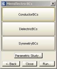
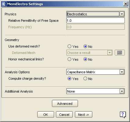
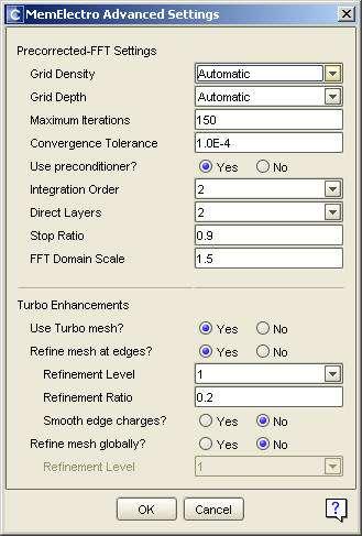
20 MemElectro User Interface


21 MemElectro Boundary Conditions Conductor BC s Dielectric BC s Fixed: Use when conductor potential or charge is known Suppress: Use to remove a conductor from capacitive simulations Float: Use when potential is unknown -Can suppress if not of interest in particular simulation -Adding dielectrics causes more panels to be created for simulation, dramatically increasing simulation time

22 Analyzer - MemMech Can perform a variety of multiphysics analyses in steady state or transient Mechanical/Thermomechanic al/electrothermomechanical Mechanical deformation Stress and Rxn forces Thermal Piezoelectric Modal analysis settings no stress/strain calculations

 Patch1, 2, 3: Name of surface")
23 MemMech BC s SurfaceBCs: surface boundary conditions, e.g fixing and loading. Volume BCs: Temperature, stress gradient or acceleration. LinkageBCs: Couple or link different meshes ContactBCs: Used to set contact conditions between one or more parts FixType: Load condition on surface (fixed, load patch, temperature, etc) Patch1, 2, 3: Name of surface (from solid model) And1, 2: Boolean and/or operations connecting load surface. Or: is additive!
24 Modal Analyses Can perform modal analyses similar to Comsol/Ansys, but potentiallyy more accurate due to model construction directly from GDSII files No stress/strain calculated Have to make sure and apply the correct boundary conditions! Can consider effects of: Electrostatic spring softening Residual Stress Make sure to suppress unnecessary structures for modal simulation (and other mechanical simulations)
25 Harmonic Analyses Can perform direct simulation of excitation by a harmonic waveform (pressure, temperature, voltage, etc) Good to perform a modal analysis first to determine correct frequency range Can select arbitrary number of frequencies to sweep through Considers some damping effects Modal damping (function of critical damping of system particular to each eigenmode) Thermoelastic damping


26 Contact boundary conditions Contact BCs defined between two continuous surfaces Surface Master should be more rigid topatch slave can bend, stress, etc Can only use linear meshes for master and slave surfaces Master surface can expand to improve stability Can simulate complex interactions Friction Soft contact (both deforming)


27 Damping Coventorware can account for several common types of damping, including anchor loss, TED, material losses, and stokes damping Ex. Anchor Loss Uses fictitious infinite substrate to transmit energy (QuietBoundary) Outputs Q factors for different frequencies Working directly with Coventor application engineers on implementing for Nguyen group resonators Excitation Origin Anchor-Substrate interface patches Slide 27
 to be multiplied by transient")


28 Transient Analysis Allows two load conditions (thermal, electrical, or mechanical) to be multiplied by transient waveforms Makes it possible to simulate stress/strain, displacement, forces, etc at resonance, as opposed to statically Allows for nonlinearities such as contact boundaries and anchor losses EXTREMELEY computationally intensive don t use to debug
29 Transient Results
30 Transient Results


31 Analyzer - CoSolve CoSolve is a coupled Electrostatic- Mechanical solver Combination the MemElectro and MemMech Can solve iteratively or simultaneously First define mechanical BCs in MemMech, then use CoSolve menu to define electrical BCs
 as opposed to BEM Needs to mesh the gap Partition the model to avoid fringing fields In general, cannot use if fringing fields are")
32 Coupled Electrostatic (MemMech) If a transient CoSolve-type simulation is desired, a coupled electro-mechanical simulation can be conducted inside MemMech Applies potential difference between two surfaces Uses Abaqus solver (FEM) as opposed to BEM Needs to mesh the gap Partition the model to avoid fringing fields In general, cannot use if fringing fields are important


33 Parameterized Studies View trends or sensitivity to a given parameter Sets variations automatically and iterates using appropriate solver. Use the Mech BCs window to apply the trajectory Apply the Mech BC the appropriate boundary condition Use the trajectory window to define an incremental range of steps, eg. From 1 to 101 MPa


34 Visualization -2D Query gui is customized for each module. Simulation data tables can be exported. Control the visible lines using Plot Attributes, and hide/show the relevant zones. Control the axis range and type using the Axis menu.

35 Visualization 3D Interactive slicing cross sections Transparent plots (show multiple plots at once) Data manipulation Hide structures Deform using displacements Plot annotation.avi movie output, plus user frame rate control and higher resolution capability. Values at all nodes in parabolic elements are now used high resolutions


36 Advanced Solvers PZE Solver - MemMech can be configured for piezoelectric analysis. Computes stress that develops when deformation is prevented or restrained by surrounding materials Assumes linear coupling relationship between electrical displacement or field strength and mechanical factors. MemPZR - uses stress and material s PZR coefficients to compute the piezoresistive sensor s potential field and the resulting change in current. Facilitates design of multiple piezoresistive sensors of arbitrary shape and size To match process parameters, such as diffusion depth, the user may independently control the process-dependent geometry of each resistor. MemHenry - computes frequencydependent resistance and inductance matrices for a set of conductors Accurate, 3D computation can be applied to on-chip passive inductor analysis and parasitic extraction for packaging analysis. Builds SPICE models, which can be configured to capture proximity effects.
37 Appendix


38 Meshing Study Single Axis Mirror Example Separate devices into constituent parts Optimize meshes for tether and plate separately As you change the density of the mesh, observe how results like displacement, stress, and rxn forces change Tether Electrode Plate Tether x=10 μm; y=2 μm; z=4 μm x=2 μm; y=2 μm; z=2 μm x=1 μm; y=1 μm; z=1 μm


39 Meshing Study A quantity cannot be measured more accurately than the mesh that is used to resolve it! A mesh by itself does not guarantee accurate results it must be verified as returning reliable data
40 MemMech PZE Structural nonlinearity in PZE procedures Stress stiffening effect in structural, modal and harmonic analysis Direct integration steady state dynamic procedure used In comparison to modal based direct integration requires more resources but generates more accurate result


41 MemPZR Structural and PZR meshes can live in separate models For Mechanical Piezoresistive analysis structural part is set in MemMech. MemPZR GUI shows structural model In Piezoresistive analysis structural results must be imported
CoventorWare 10 Overview
 CoventorWare 10 Overview 노용주 이디앤씨 June, 2015 Distributed and supported by ED&C CoventorWare: Coventor s MEMS Multi-Physics Platform for 10+ Years Sensing Mechanical Electrical Transduction Accelerometers
Section 2: Beam Design
 Section 2: Beam Design Version 2008 Section 2: Beam Design In MEMS design, the beam structure has many applications, including sensors, accelerometers, and RF switches. This section investigates two beam
New paradigm for MEMS+IC Co-development
 New paradigm for MEMS+IC Co-development MEMS 진보된스마트세상을만듭니다. Worldwide First MEMS+IC Co-development Solution New paradigm for MEMS+IC Co-development A New Paradigm for MEMS+IC Development MEMS design
CHAPTER 4 DESIGN AND MODELING OF CANTILEVER BASED ELECTROSTATICALLY ACTUATED MICROGRIPPER WITH IMPROVED PERFORMANCE
 92 CHAPTER 4 DESIGN AND MODELING OF CANTILEVER BASED ELECTROSTATICALLY ACTUATED MICROGRIPPER WITH IMPROVED PERFORMANCE 4.1 INTRODUCTION Bio-manipulation techniques and tools including optical tweezers,
Example 24 Spring-back
 Example 24 Spring-back Summary The spring-back simulation of sheet metal bent into a hat-shape is studied. The problem is one of the famous tests from the Numisheet 93. As spring-back is generally a quasi-static
Workshop 15. Single Pass Rolling of a Thick Plate
 Introduction Workshop 15 Single Pass Rolling of a Thick Plate Rolling is a basic manufacturing technique used to transform preformed shapes into a form suitable for further processing. The rolling process
ECE421: Electronics for Instrumentation
 ECE421: Electronics for Instrumentation Lecture #8: Introduction to FEA & ANSYS Mostafa Soliman, Ph.D. March 23 rd 2015 Mostafa Soliman, Ph.D. 1 Outline Introduction to Finite Element Analysis Introduction
3) Computer Aided Design of microsystems structures and elements 3.1. INTRODUCTION
 Computer Aided Design of microsystems structures and elements 3.1. INTRODUCTION") 3) Computer Aided Design of microsystems structures and elements 3.1. INTRODUCTION MEMS and microsystems design differs from traditional engineering design is that in additional to the design for structural
3) Computer Aided Design of microsystems structures and elements 3.1. INTRODUCTION MEMS and microsystems design differs from traditional engineering design is that in additional to the design for structural
QUEST 3D RLCG Extraction Depending on Frequency. RF Structures Parasitic Extractor
 QUEST 3D RLCG Extraction Depending on Frequency RF Structures Parasitic Extractor Introduction Type of Simulation Inputs / Outputs Graphical Interface Technology Process Layout Field Solver Output DOE
Outline. Darren Wang ADS Momentum P2
 Outline Momentum Basics: Microstrip Meander Line Momentum RF Mode: RFIC Launch Designing with Momentum: Via Fed Patch Antenna Momentum Techniques: 3dB Splitter Look-alike Momentum Optimization: 3 GHz Band
Coupled Analysis of FSI
 Coupled Analysis of FSI Qin Yin Fan Oct. 11, 2008 Important Key Words Fluid Structure Interface = FSI Computational Fluid Dynamics = CFD Pressure Displacement Analysis = PDA Thermal Stress Analysis = TSA
Using Sonnet in a Cadence Virtuoso Design Flow
 Using Sonnet in a Cadence Virtuoso Design Flow Purpose of this document: This document describes the Sonnet plug-in integration for the Cadence Virtuoso design flow, for silicon accurate EM modelling of
CHAPTER 1. Introduction
 ME 475: Computer-Aided Design of Structures 1-1 CHAPTER 1 Introduction 1.1 Analysis versus Design 1.2 Basic Steps in Analysis 1.3 What is the Finite Element Method? 1.4 Geometrical Representation, Discretization
Generative Part Structural Analysis Fundamentals
 CATIA V5 Training Foils Generative Part Structural Analysis Fundamentals Version 5 Release 19 September 2008 EDU_CAT_EN_GPF_FI_V5R19 About this course Objectives of the course Upon completion of this course
PTC Creo Simulate. Features and Specifications. Data Sheet
 PTC Creo Simulate PTC Creo Simulate gives designers and engineers the power to evaluate structural and thermal product performance on your digital model before resorting to costly, time-consuming physical
MRI Induced Heating of a Pacemaker. Peter Krenz, Application Engineer
 MRI Induced Heating of a Pacemaker Peter Krenz, Application Engineer 1 Problem Statement Electric fields generated during MRI exposure are dissipated in tissue of the human body resulting in a temperature
Fully-Coupled Thermo-Mechanical Analysis
 Fully-Coupled Thermo-Mechanical Analysis Type of solver: ABAQUS CAE/Standard Adapted from: ABAQUS Example Problems Manual Extrusion of a Cylindrical Aluminium Bar with Frictional Heat Generation Problem
CHAPTER 6 EXPERIMENTAL AND FINITE ELEMENT SIMULATION STUDIES OF SUPERPLASTIC BOX FORMING
 113 CHAPTER 6 EXPERIMENTAL AND FINITE ELEMENT SIMULATION STUDIES OF SUPERPLASTIC BOX FORMING 6.1 INTRODUCTION Superplastic properties are exhibited only under a narrow range of strain rates. Hence, it
ANSYS 5.6 Tutorials Lecture # 2 - Static Structural Analysis
 R50 ANSYS 5.6 Tutorials Lecture # 2 - Static Structural Analysis Example 1 Static Analysis of a Bracket 1. Problem Description: The objective of the problem is to demonstrate the basic ANSYS procedures
SIMULATION CAPABILITIES IN CREO
 SIMULATION CAPABILITIES IN CREO Enhance Your Product Design with Simulation & Using digital prototypes to understand how your designs perform in real-world conditions is vital to your product development
Powerful features (1)
") HFSS Overview Powerful features (1) Tangential Vector Finite Elements Provides only correct physical solutions with no spurious modes Transfinite Element Method Adaptive Meshing r E = t E γ i i ( x, y,
HFSS Overview Powerful features (1) Tangential Vector Finite Elements Provides only correct physical solutions with no spurious modes Transfinite Element Method Adaptive Meshing r E = t E γ i i ( x, y,
Lecture 2: Introduction
 Lecture 2: Introduction v2015.0 Release ANSYS HFSS for Antenna Design 1 2015 ANSYS, Inc. Multiple Advanced Techniques Allow HFSS to Excel at a Wide Variety of Applications Platform Integration and RCS
Accelerating Finite Element Analysis in MATLAB with Parallel Computing
 MATLAB Digest Accelerating Finite Element Analysis in MATLAB with Parallel Computing By Vaishali Hosagrahara, Krishna Tamminana, and Gaurav Sharma The Finite Element Method is a powerful numerical technique
Design Optimization of a Weather Radar Antenna using Finite Element Analysis (FEA) and Computational Fluid Dynamics (CFD)
 and Computational Fluid Dynamics (CFD)") Design Optimization of a Weather Radar Antenna using Finite Element Analysis (FEA) and Computational Fluid Dynamics (CFD) Fernando Prevedello Regis Ataídes Nícolas Spogis Wagner Ortega Guedes Fabiano Armellini
Design Optimization of a Weather Radar Antenna using Finite Element Analysis (FEA) and Computational Fluid Dynamics (CFD) Fernando Prevedello Regis Ataídes Nícolas Spogis Wagner Ortega Guedes Fabiano Armellini
Exercise 2: Mesh Resolution, Element Shapes, Basis Functions & Convergence Analyses
 Exercise 2: Mesh Resolution, Element Shapes, Basis Functions & Convergence Analyses Goals In this exercise, we will explore the strengths and weaknesses of different element types (tetrahedrons vs. hexahedrons,
Creating and Analyzing a Simple Model in Abaqus/CAE
 Appendix B: Creating and Analyzing a Simple Model in Abaqus/CAE The following section is a basic tutorial for the experienced Abaqus user. It leads you through the Abaqus/CAE modeling process by visiting
Appendix B: Creating and Analyzing a Simple Model in Abaqus/CAE
 Getting Started with Abaqus: Interactive Edition Appendix B: Creating and Analyzing a Simple Model in Abaqus/CAE The following section is a basic tutorial for the experienced Abaqus user. It leads you
LS-DYNA s Linear Solver Development Phase 2: Linear Solution Sequence
 LS-DYNA s Linear Solver Development Phase 2: Linear Solution Sequence Allen T. Li 1, Zhe Cui 2, Yun Huang 2 1 Ford Motor Company 2 Livermore Software Technology Corporation Abstract This paper continues
Speed, Accuracy and Automation in MEMS Simulation and Development C. J. Welham, Coventor, Paris
 Speed, Accuracy and Automation in MEMS Simulation and Development C. J. Welham, Coventor, Paris MEMS Design & Simulation Challenges Overview Simulation Challenges and Approaches Validation Case Studies
Solid Conduction Tutorial
 SECTION 1 1 SECTION 1 The following is a list of files that will be needed for this tutorial. They can be found in the Solid_Conduction folder. Exhaust-hanger.tdf Exhaust-hanger.ntl 1.0.1 Overview The
ixcube 4-10 Brief introduction for membrane and cable systems.
 ixcube 4-10 Brief introduction for membrane and cable systems. ixcube is the evolution of 20 years of R&D in the field of membrane structures so it takes a while to understand the basic features. You must
SIMULATION CAPABILITIES IN CREO. Enhance Your Product Design with Simulation & Analysis
 SIMULATION CAPABILITIES IN CREO Enhance Your Product Design with Simulation & Using digital prototypes to understand how your designs perform in real-world conditions is vital to your product development
Introduction to Abaqus. About this Course
 Introduction to Abaqus R 6.12 About this Course Course objectives Upon completion of this course you will be able to: Use Abaqus/CAE to create complete finite element models. Use Abaqus/CAE to submit and
SAMCEF for ROTORS. Chapter 3.2: Rotor modeling. This document is the property of SAMTECH S.A. MEF A, Page 1
 SAMCEF for ROTORS Chapter 3.2: Rotor modeling This document is the property of SAMTECH S.A. MEF 101-03-2-A, Page 1 Table of contents Introduction Introduction 1D Model 2D Model 3D Model 1D Models: Beam-Spring-
COMPUTER AIDED ENGINEERING. Part-1
 COMPUTER AIDED ENGINEERING Course no. 7962 Finite Element Modelling and Simulation Finite Element Modelling and Simulation Part-1 Modeling & Simulation System A system exists and operates in time and space.
Engineering Analysis
 Engineering Analysis with SOLIDWORKS Simulation 2018 Paul M. Kurowski SDC PUBLICATIONS Better Textbooks. Lower Prices. www.sdcpublications.com Powered by TCPDF (www.tcpdf.org) Visit the following websites
For functionality and CAD/EDA import filter, see technical specifications of the CST STUDIO SUITE
 CST MICROWAVE STUDIO Technical Specification 1 May 2015 Frontend Module For functionality and CAD/EDA import filter, see technical specifications of the CST STUDIO SUITE Transient Solver Module Fast and
ANSYS Workbench Guide
 ANSYS Workbench Guide Introduction This document serves as a step-by-step guide for conducting a Finite Element Analysis (FEA) using ANSYS Workbench. It will cover the use of the simulation package through
NEi FEA. IRONCAD Advanced FEA. IRONCAD Advanced FEA. NEi FEA
 2011 Overview has been designed as a universal, adaptive and user-friendly graphical user interface for geometrical modeling, data input and visualization of results for all types of numerical simulation
New Technologies in CST STUDIO SUITE CST COMPUTER SIMULATION TECHNOLOGY
 New Technologies in CST STUDIO SUITE 2016 Outline Design Tools & Modeling Antenna Magus Filter Designer 2D/3D Modeling 3D EM Solver Technology Cable / Circuit / PCB Systems Multiphysics CST Design Tools
2: Static analysis of a plate
 2: Static analysis of a plate Topics covered Project description Using SolidWorks Simulation interface Linear static analysis with solid elements Finding reaction forces Controlling discretization errors
THE EFFECTS OF THE PLANFORM SHAPE ON DRAG POLAR CURVES OF WINGS: FLUID-STRUCTURE INTERACTION ANALYSES RESULTS
 March 18-20, 2013 THE EFFECTS OF THE PLANFORM SHAPE ON DRAG POLAR CURVES OF WINGS: FLUID-STRUCTURE INTERACTION ANALYSES RESULTS Authors: M.R. Chiarelli, M. Ciabattari, M. Cagnoni, G. Lombardi Speaker:
CAD - How Computer Can Aid Design?
 CAD - How Computer Can Aid Design? Automating Drawing Generation Creating an Accurate 3D Model to Better Represent the Design and Allowing Easy Design Improvements Evaluating How Good is the Design and
Validation Report: Additional Data Mapping to Structural Analysis Packages
 Autodesk Moldflow Structural Alliance 2012 Validation Report: Additional Data Mapping to Structural Analysis Packages Mapping process-induced stress data from Autodesk Moldflow Insight Dual Domain and
PTC Newsletter January 14th, 2002
 PTC Email Newsletter January 14th, 2002 PTC Product Focus: Pro/MECHANICA (Structure) Tip of the Week: Creating and using Rigid Connections Upcoming Events and Training Class Schedules PTC Product Focus:
Abaqus/CAE Axisymmetric Tutorial (Version 2016)
") Abaqus/CAE Axisymmetric Tutorial (Version 2016) Problem Description A round bar with tapered diameter has a total load of 1000 N applied to its top face. The bottom of the bar is completely fixed. Determine
Abaqus/CAE Axisymmetric Tutorial (Version 2016) Problem Description A round bar with tapered diameter has a total load of 1000 N applied to its top face. The bottom of the bar is completely fixed. Determine
Revision of the SolidWorks Variable Pressure Simulation Tutorial J.E. Akin, Rice University, Mechanical Engineering. Introduction
 Revision of the SolidWorks Variable Pressure Simulation Tutorial J.E. Akin, Rice University, Mechanical Engineering Introduction A SolidWorks simulation tutorial is just intended to illustrate where to
Outline. COMSOL Multyphysics: Overview of software package and capabilities
 COMSOL Multyphysics: Overview of software package and capabilities Lecture 5 Special Topics: Device Modeling Outline Basic concepts and modeling paradigm Overview of capabilities Steps in setting-up a
Abaqus CAE Tutorial 6: Contact Problem
 ENGI 7706/7934: Finite Element Analysis Abaqus CAE Tutorial 6: Contact Problem Problem Description In this problem, a segment of an electrical contact switch (steel) is modeled by displacing the upper
Executive Summary Sefea Basic Theory
 Executive Summary Sefea is one of the newest generations of enriched finite element methods. Developed specifically for low-order 4-node tetrahedron and 3-node triangle in the CAE environment, Sefea achieves
Modelling Flat Spring Performance Using FEA
 Modelling Flat Spring Performance Using FEA Blessing O Fatola, Patrick Keogh and Ben Hicks Department of Mechanical Engineering, University of Corresponding author bf223@bath.ac.uk Abstract. This paper
SolidWorks. An Overview of SolidWorks and Its Associated Analysis Programs
 An Overview of SolidWorks and Its Associated Analysis Programs prepared by Prof. D. Xue University of Calgary SolidWorks - a solid modeling CAD tool. COSMOSWorks - a design analysis system fully integrated
Using MSC.Nastran for Explicit FEM Simulations
 3. LS-DYNA Anwenderforum, Bamberg 2004 CAE / IT III Using MSC.Nastran for Explicit FEM Simulations Patrick Doelfs, Dr. Ingo Neubauer MSC.Software GmbH, D-81829 München, Patrick.Doelfs@mscsoftware.com Abstract:
Analysis of a silicon piezoresistive pressure sensor
 Analysis of a silicon piezoresistive pressure sensor This lab uses the general purpose finite element solver COMSOL to determine the stress in the resistors in a silicon piezoresistive pressure sensor
Hydro-elastic analysis of a propeller using CFD and FEM co-simulation
 Fifth International Symposium on Marine Propulsors smp 17, Espoo, Finland, June 2017 Hydro-elastic analysis of a propeller using CFD and FEM co-simulation Vesa Nieminen 1 1 VTT Technical Research Centre
SETTLEMENT OF A CIRCULAR FOOTING ON SAND
 1 SETTLEMENT OF A CIRCULAR FOOTING ON SAND In this chapter a first application is considered, namely the settlement of a circular foundation footing on sand. This is the first step in becoming familiar
30 th Anniversary Event. New features in Opera By: Kevin Ward. OPTIMIZER Automatically selects and manages multiple goalseeking
 FEA ANALYSIS General-purpose multiphysics design and analysis software for a wide range of applications OPTIMIZER Automatically selects and manages multiple goalseeking algorithms INTEROPERABILITY Built-in
3. Preprocessing of ABAQUS/CAE
 3.1 Create new model database 3. Preprocessing of ABAQUS/CAE A finite element analysis in ABAQUS/CAE starts from create new model database in the toolbar. Then save it with a name user defined. To build
CHAPTER 4. Numerical Models. descriptions of the boundary conditions, element types, validation, and the force
 CHAPTER 4 Numerical Models This chapter presents the development of numerical models for sandwich beams/plates subjected to four-point bending and the hydromat test system. Detailed descriptions of the
Abaqus/CAE (ver. 6.10) Stringer Tutorial
 Stringer Tutorial") Abaqus/CAE (ver. 6.10) Stringer Tutorial Problem Description A table made of steel tubing with a solid steel top and shelf is loaded with an oblique impulse load. Determine the transient response of the
Abaqus/CAE (ver. 6.10) Stringer Tutorial Problem Description A table made of steel tubing with a solid steel top and shelf is loaded with an oblique impulse load. Determine the transient response of the
SOLIDWORKS Simulation Avoiding Singularities
 SOLIDWORKS Simulation Avoiding Singularities What is a Singularity? A singularity is a function s divergence into infinity. SOLIDWORKS Simulation occasionally produces stress (or heat flux) singularities.
ES 128: Computer Assignment #4. Due in class on Monday, 12 April 2010
 ES 128: Computer Assignment #4 Due in class on Monday, 12 April 2010 Task 1. Study an elastic-plastic indentation problem. This problem combines plasticity with contact mechanics and has many rich aspects.
EN1740 Computer Aided Visualization and Design Spring /26/2012 Brian C. P. Burke
 EN1740 Computer Aided Visualization and Design Spring 2012 4/26/2012 Brian C. P. Burke Last time: More motion analysis with Pro/E Tonight: Introduction to external analysis products ABAQUS External Analysis
Simulating Sinkage & Trim for Planing Boat Hulls. A Fluent Dynamic Mesh 6DOF Tutorial
 Simulating Sinkage & Trim for Planing Boat Hulls A Fluent Dynamic Mesh 6DOF Tutorial 1 Introduction Workshop Description This workshop describes how to perform a transient 2DOF simulation of a planing
Tutorial 1: Welded Frame - Problem Description
 Tutorial 1: Welded Frame - Problem Description Introduction In this first tutorial, we will analyse a simple frame: firstly as a welded frame, and secondly as a pin jointed truss. In each case, we will
Tutorial 7 Finite Element Groundwater Seepage. Steady state seepage analysis Groundwater analysis mode Slope stability analysis
 Tutorial 7 Finite Element Groundwater Seepage Steady state seepage analysis Groundwater analysis mode Slope stability analysis Introduction Within the Slide program, Slide has the capability to carry out
Autodesk Moldflow Insight AMI Cool Analysis Products
 Autodesk Moldflow Insight 2012 AMI Cool Analysis Products Revision 1, 22 March 2012. This document contains Autodesk and third-party software license agreements/notices and/or additional terms and conditions
3D Finite Element Software for Cracks. Version 3.2. Benchmarks and Validation
 3D Finite Element Software for Cracks Version 3.2 Benchmarks and Validation October 217 1965 57 th Court North, Suite 1 Boulder, CO 831 Main: (33) 415-1475 www.questintegrity.com http://www.questintegrity.com/software-products/feacrack
Simulating Drilling Processes with DEFORM-3D
 Simulating Drilling Processes with DEFORM-3D Due to the number of revolutions of a drill necessary to establish characteristic behavior, drilling simulations in DEFORM are time consuming. Therefore, every
An Improved Meshing Technique and its Application in the Analysis of Large and Complex MEMS Systems
 An Improved Meshing Technique and its Application in the Analysis of Large and Complex MEMS Systems Yie He, James Marchetti, Fariborz Maseeh IntelliSense Corporation 16 Upton Drive, Wilmington, MA 01887
SIMCENTER 12 ACOUSTICS Beta
 SIMCENTER 12 ACOUSTICS Beta 1/80 Contents FEM Fluid Tutorial Compressor Sound Radiation... 4 1. Import Structural Mesh... 5 2. Create an Acoustic Mesh... 7 3. Load Recipe... 20 4. Vibro-Acoustic Response
Sliding Split Tube Telescope
 LESSON 15 Sliding Split Tube Telescope Objectives: Shell-to-shell contact -accounting for shell thickness. Creating boundary conditions and loads by way of rigid surfaces. Simulate large displacements,
30 th Anniversary Event. New features in Opera By Nigel Atkinson, PhD. OPTIMIZER Automatically selects and manages multiple goalseeking
 FEA ANALYSIS General-purpose multiphysics design and analysis software for a wide range of applications OPTIMIZER Automatically selects and manages multiple goalseeking algorithms INTEROPERABILITY Built-in
Using ANSYS and CFX to Model Aluminum Reduction Cell since1984 and Beyond. Dr. Marc Dupuis
 Using ANSYS and CFX to Model Aluminum Reduction Cell since1984 and Beyond Dr. Marc Dupuis 1980-84, 2D potroom ventilation model Physical model 1980-84, 2D potroom ventilation model Experimental results
Appendix P. Multi-Physics Simulation Technology in NX. Christian Ruel (Maya Htt, Canada)
") 251 Appendix P Multi-Physics Simulation Technology in NX Christian Ruel (Maya Htt, Canada) 252 Multi-Physics Simulation Technology in NX Abstract As engineers increasingly rely on simulation models within
251 Appendix P Multi-Physics Simulation Technology in NX Christian Ruel (Maya Htt, Canada) 252 Multi-Physics Simulation Technology in NX Abstract As engineers increasingly rely on simulation models within
Tutorial. BOSfluids. Water hammer (part 3) Dynamic Analysis using Caesar II
 Dynamic Analysis using Caesar II") BOSfluids Tutorial Water hammer (part 3) Dynamic Analysis using Caesar II The Water hammer tutorial is a 3 part tutorial describing the phenomena of water hammer in a piping system and how BOSfluids can
BOSfluids Tutorial Water hammer (part 3) Dynamic Analysis using Caesar II The Water hammer tutorial is a 3 part tutorial describing the phenomena of water hammer in a piping system and how BOSfluids can
CHAPTER 8 FINITE ELEMENT ANALYSIS
 If you have any questions about this tutorial, feel free to contact Wenjin Tao (w.tao@mst.edu). CHAPTER 8 FINITE ELEMENT ANALYSIS Finite Element Analysis (FEA) is a practical application of the Finite
CHAPTER-10 DYNAMIC SIMULATION USING LS-DYNA
 DYNAMIC SIMULATION USING LS-DYNA CHAPTER-10 10.1 Introduction In the past few decades, the Finite Element Method (FEM) has been developed into a key indispensable technology in the modeling and simulation
Installation Guide. Beginners guide to structural analysis
 Installation Guide To install Abaqus, students at the School of Civil Engineering, Sohngaardsholmsvej 57, should log on to \\studserver, whereas the staff at the Department of Civil Engineering should
NX Advanced FEM. fact sheet
 Advanced FEM fact sheet www.ugs.com Summary Advanced FEM is a comprehensive multi-cad finite element modeling and results visualization product that is designed to meet the needs of experienced CAE analysts.
Nouveautés ANSYS pour le calcul structurel et l impression 3D. CADFEM 2017 ANSYS Additive Manufacturing
 Titelmasterformat Journée Technologique durch AddiPole Klicken bearbeiten Nouveautés ANSYS pour le calcul structurel et l impression 3D Titelmasterformat Structural design with durch ANSYS Klicken bearbeiten
Analysis Steps 1. Start Abaqus and choose to create a new model database
 Source: Online tutorials for ABAQUS Problem Description The two dimensional bridge structure, which consists of steel T sections (b=0.25, h=0.25, I=0.125, t f =t w =0.05), is simply supported at its lower
Multi-Objective Optimization of a Ball Grid Array Using modefrontier & COMSOL Multiphysics
 Excerpt from the Proceedings of the COMSOL Conference 2009 Milan Multi-Objective Optimization of a Ball Grid Array Using modefrontier & COMSOL Multiphysics H. Strandberg *,1, T. Makkonen 2, J. Leinvuo
Advanced Surface Based MoM Techniques for Packaging and Interconnect Analysis
 Electrical Interconnect and Packaging Advanced Surface Based MoM Techniques for Packaging and Interconnect Analysis Jason Morsey Barry Rubin, Lijun Jiang, Lon Eisenberg, Alina Deutsch Introduction Fast
ANSYS AIM 16.0 Overview. AIM Program Management
 1 2015 ANSYS, Inc. September 27, 2015 ANSYS AIM 16.0 Overview AIM Program Management 2 2015 ANSYS, Inc. September 27, 2015 Today s Simulation Challenges Leveraging simulation across engineering organizations
Analysis of Fluid-Structure Interaction Effects of Liquid-Filled Container under Drop Testing
 Kasetsart J. (Nat. Sci.) 42 : 165-176 (2008) Analysis of Fluid-Structure Interaction Effects of Liquid-Filled Container under Drop Testing Chakrit Suvanjumrat*, Tumrong Puttapitukporn and Satjarthip Thusneyapan
GEOMETRY MODELING & GRID GENERATION
 GEOMETRY MODELING & GRID GENERATION Dr.D.Prakash Senior Assistant Professor School of Mechanical Engineering SASTRA University, Thanjavur OBJECTIVE The objectives of this discussion are to relate experiences
Problem description. The FCBI-C element is used in the fluid part of the model.
 Problem description This tutorial illustrates the use of ADINA for analyzing the fluid-structure interaction (FSI) behavior of a flexible splitter behind a 2D cylinder and the surrounding fluid in a channel.
High-Frequency Algorithmic Advances in EM Tools for Signal Integrity Part 1. electromagnetic. (EM) simulation. tool of the practic-
 simulation. tool of the practic-") From January 2011 High Frequency Electronics Copyright 2011 Summit Technical Media, LLC High-Frequency Algorithmic Advances in EM Tools for Signal Integrity Part 1 By John Dunn AWR Corporation Only 30
From January 2011 High Frequency Electronics Copyright 2011 Summit Technical Media, LLC High-Frequency Algorithmic Advances in EM Tools for Signal Integrity Part 1 By John Dunn AWR Corporation Only 30
Offshore Platform Fluid Structure Interaction (FSI) Simulation
 Simulation") Offshore Platform Fluid Structure Interaction (FSI) Simulation Ali Marzaban, CD-adapco Murthy Lakshmiraju, CD-adapco Nigel Richardson, CD-adapco Mike Henneke, CD-adapco Guangyu Wu, Chevron Pedro M. Vargas,
Offshore Platform Fluid Structure Interaction (FSI) Simulation Ali Marzaban, CD-adapco Murthy Lakshmiraju, CD-adapco Nigel Richardson, CD-adapco Mike Henneke, CD-adapco Guangyu Wu, Chevron Pedro M. Vargas,
MEMS Pro v5.1 Layout Tutorial Physical Design Mask complexity
 MEMS Pro v5.1 Layout Tutorial 1 Physical Design Mask complexity MEMS masks are complex with curvilinear geometries Verification of manufacturing design rules is important Automatic generation of mask layout
Learning Module 8 Shape Optimization
 Learning Module 8 Shape Optimization What is a Learning Module? Title Page Guide A Learning Module (LM) is a structured, concise, and self-sufficient learning resource. An LM provides the learner with
Maxwell v Example (2D/3D Transient) Core Loss. Transformer Core Loss Calculation in Maxwell 2D and 3D
 Core Loss. Transformer Core Loss Calculation in Maxwell 2D and 3D") Transformer Core Loss Calculation in Maxwell 2D and 3D This example analyzes cores losses for a 3ph power transformer having a laminated steel core using Maxwell 2D and 3D. The transformer is rated 115-13.8kV,
Transformer Core Loss Calculation in Maxwell 2D and 3D This example analyzes cores losses for a 3ph power transformer having a laminated steel core using Maxwell 2D and 3D. The transformer is rated 115-13.8kV,
Torsional-lateral buckling large displacement analysis with a simple beam using Abaqus 6.10
 Torsional-lateral buckling large displacement analysis with a simple beam using Abaqus 6.10 This document contains an Abaqus tutorial for performing a buckling analysis using the finite element program
Modeling Foundations in RS
 Modeling Foundations in RS 3 Piled Raft Modeling in RS 3 Deep foundation piles are commonly used to increase foundation stability and to increase the bearing capacity of structural systems. The design
Simulating Microsystems
 Simulating Microsystems David Bindel UC Berkeley, EECS Simulating Microsystems p.1/21 Overview Microsystems overview Simulation software Case study: gap-closing actuator Simulating Microsystems p.2/21
Introduction to FEM Modeling
 Total Analysis Solution for Multi-disciplinary Optimum Design Apoorv Sharma midas NFX CAE Consultant 1 1. Introduction 2. Element Types 3. Sample Exercise: 1D Modeling 4. Meshing Tools 5. Loads and Boundary
Lecture 7: Mesh Quality & Advanced Topics. Introduction to ANSYS Meshing Release ANSYS, Inc. February 12, 2015
 Lecture 7: Mesh Quality & Advanced Topics 15.0 Release Introduction to ANSYS Meshing 1 2015 ANSYS, Inc. February 12, 2015 Overview In this lecture we will learn: Impact of the Mesh Quality on the Solution
Best Practices for Contact Modeling using ANSYS
 Best Practices for Contact Modeling using ANSYS 朱永谊 / R&D Fellow ANSYS 1 2016 ANSYS, Inc. August 12, 2016 ANSYS UGM 2016 Why are these best practices important? Contact is the most common source of nonlinearity
CECOS University Department of Electrical Engineering. Wave Propagation and Antennas LAB # 1
 CECOS University Department of Electrical Engineering Wave Propagation and Antennas LAB # 1 Introduction to HFSS 3D Modeling, Properties, Commands & Attributes Lab Instructor: Amjad Iqbal 1. What is HFSS?