HFSS Ansys ANSYS, Inc. All rights reserved. 1 ANSYS, Inc. Proprietary
|
|
|
- Irene Allen
- 5 years ago
- Views:
Transcription
1 HFSS 12.0 Ansys 2009 ANSYS, Inc. All rights reserved. 1 ANSYS, Inc. Proprietary
2 Comparison of HFSS 11 and HFSS 12 for JSF Antenna Model UHF blade antenna on Joint Strike Fighter Inherent improvements in runtime and RAM usage for this example Model converges to desired accuracy in 50% of the time using 20% less RAM JSF Antenna Model (8 CPUs) Adaptive Passes to Reach S = 0.02 Tetrahedra Runtime (min) RAM (GB) HFSS 11: 2 nd order basis and iterative solver HFSS 12: 2 nd order basis and iterative solver HFSS 12: mixed order basis and iterative solver 6 162k k k ANSYS, Inc. All rights reserved. 2 ANSYS, Inc. Proprietary
3 (Option) DSO (Distributed Solve Option) 2009 ANSYS, Inc. All rights reserved. 3 ANSYS, Inc. Proprietary
4 Balancing Time versus Resources DSO (Distributed Solve Option) In the past, users had to make trade-off decisions about how much to simulate in a limited amount of time (eg, overnight) Multiple geometric variations Pro: optimizes structure for best electrical performance Con: requires more run-time simulation time increases with # of variations Solve for more frequency points Pro: improves results accuracy Con: requires more run-time simulation time increases with # of freq. points 2009 ANSYS, Inc. All rights reserved. 4 ANSYS, Inc. Proprietary


5 Reduce Simulation Run Times Trace width and spacing parameterization using Q3D Distributed Solve Option in action DSO In Progress Trace width 2009 ANSYS, Inc. All rights reserved. 5 ANSYS, Inc. Proprietary

6 Optimize Simulation Run Times DSO Setup 25 Parametric Case HeadNode: Dual-Dual-Core AMD 2.2GHz 16GB RAM Nodes: 16 Dual Processor AMD 2.6GHz 8GB RAM Nominal Case 6 hrs 51 min DSO Solution Time 26 min!!! Time Savings 15x speed up! 6hr 51 min DSO Solution Time 2009 ANSYS, Inc. All rights reserved. 6 ANSYS, Inc. Proprietary
7 (Option) DDM (Domain Decomposition Solver) 2009 ANSYS, Inc. All rights reserved. 7 ANSYS, Inc. Proprietary
8 Review DDM Technique DDM subdivides a mesh into smaller mesh subdomains that are solved in parallel. A master node iteratively solves for total solution Subdivision into domains is automated Easy to use!!! The user defines a set of N available compute nodes to be used for a DDM solution n=1 is the master node, single core n=2 to N are the sub-domain nodes solved with direct solver 2009 ANSYS, Inc. All rights reserved. 8 ANSYS, Inc. Proprietary


9 Example of Domain Mesh 2009 ANSYS, Inc. All rights reserved. 9 ANSYS, Inc. Proprietary


10 Domain Decomposition Process Mesh partition Mesh assembly/solve Adaptive analysis Domain 1 Domain 2 Domain N Domain iteration Domain iteration 2009 ANSYS, Inc. All rights reserved. 10 ANSYS, Inc. Proprietary
 Domain Solver (15 domains) Total Memory 33 GB 12 GB 20 GB Average Memory Final Adaptive Pass Time 33 GB 12 GB 1.35 GB 6hr 27min 1hr 20min 22 min 2009 ANSYS, Inc. All rights reserved.")
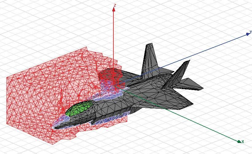
11 Antenna Example for Domain Decomposition Solver UFH blade antenna on F-35 JSF 350 MHz solution frequency Demonstrates savings in computational time and RAM Direct Solver (1 CPU) Iterative Solver (1 CPU) Domain Solver (15 domains) Total Memory 33 GB 12 GB 20 GB Average Memory Final Adaptive Pass Time 33 GB 12 GB 1.35 GB 6hr 27min 1hr 20min 22 min 2009 ANSYS, Inc. All rights reserved. 11 ANSYS, Inc. Proprietary
12 HFSS 12 New Significant Capabilities 2009 ANSYS, Inc. All rights reserved. 12 ANSYS, Inc. Proprietary
 Mesh adaptation (if needed) Conformal surface mesh generation Volume Mesh Volume mesh generation Surface Mesh Mesh coarsening")
13 HFSS 12 Includes Fundamentally Different 3D Mesher HFSS 11 (bottom up algorithm) HFSS 12 (top down algorithm) Surface Mesh model Volume Mesh model Geometric healing or repair (if model has defects) Volume mesh generation Surface mesh generation (union, stitching) Mesh adaptation (if needed) Conformal surface mesh generation Volume Mesh Volume mesh generation Surface Mesh Mesh coarsening Generally requires water-tight, clean geometric model Mesh quality depends on ACIS faceting triangulation quality Geometry flaws can cause stitching failure Less control on mesh quality Localized jump from small to large elements is possible Meshes higher percentage of models Mesh quality is ensured Automatic healing and repair More uniform mesh (gradual transition in element size) 2009 ANSYS, Inc. All rights reserved. 13 ANSYS, Inc. Proprietary


14 Example Meshing Improvement HFSS 11 HFSS 11 mesher has difficulty with intersecting curves HFSS 12 TAU mesher produces clean result HFSS ANSYS, Inc. All rights reserved. 14 ANSYS, Inc. Proprietary
 8 8.75 12 8.54 24 8.53 36 8.4 48 8.4 64 8.39 Curvilinear* 8.38 R in = 1.75mm R out = 3.")

15 Example Resonator with Concentric Spherical Dielectrics Curvilinear elements yield same accuracy as highly discretized rectilinear elements Uses 88% fewer tetrahedra Runs 16X faster # Segments f (GHz) Curvilinear* 8.38 R in = 1.75mm R out = 3.5mm Dielectric: ε in = 90 ε out = 10 Resonant frequency ~8.4 GHz For ΔF = 0.1% Mesh Elements CPU Time 36 segments 53k 00:16: curvature 6.37k 00:00:55 *I Wolff, A generalized description of the spherical three-layer resonator with an anisotropic dielectric material, IEEE AP Symp, June 1987, pp ANSYS, Inc. All rights reserved. 15 ANSYS, Inc. Proprietary
16 (Option) HFIE (High Frequency Integral Equation Solver) 2009 ANSYS, Inc. All rights reserved. 16 ANSYS, Inc. Proprietary
17 High Frequency Integral Equation Solver (HFIE) 3D method of moments (MoM) solver Integrated into exiting HFSS interface and infrastructure as additional design type Optimal method for solving large open problems Radiating problems such as larger reflector antenna or radar cross section (RCS) of aircraft platform 2009 ANSYS, Inc. All rights reserved. 17 ANSYS, Inc. Proprietary


18 HFIE: Interface Insert HFIE Design Same modeler and material setup No air box needed Excitations 2009 ANSYS, Inc. All rights reserved. 18 ANSYS, Inc. Proprietary
 Incident directions for various φ at θ=90. E θ directed. J HFIE for inc.")

19 HFIE: Cone Sphere RCS cone sphere at 9GHz. Overall length ( 20λ) Incident directions for various φ at θ=90. E θ directed. J HFIE for inc. angles φ=0 and θ=90 Data available from: A. Woo et al, Benchmark Radar Targets for the Validation of computational electromagnetic programs, IEEE AP Mag., Feb., 1993, pp ANSYS, Inc. All rights reserved. 19 ANSYS, Inc. Proprietary
20 HFIE: Cone Sphere E scatt for θ=90 with Cone_Sphere incident angles φ=θ=90 : re (db) db(retotal) [HFSS] - Freq='9GHz' IWavePhi='90deg' IWaveTheta='90deg' Theta='90deg' hfie phi (DEG) HFIE seeded λ/7: 5:30 hours (w/30 incident angles) and used <2GB HFSS pass 2: 27.5GB 7 hours real time ANSYS, Inc. All rights reserved. 20 ANSYS, Inc. Proprietary


21 HFIE: Reflector Antenna Simple single reflector excited by a dipole antenna. Diameter of reflector is 10.65λ. Measured radiation Patterns available from literature.* * Data available from Lyerly, et al, Equivalent edge current technique for accurate determination of reflector antenna patterns, IEEE AP Symp., 1993, pp ANSYS, Inc. All rights reserved. 21 ANSYS, Inc. Proprietary
22 HFIE: Reflector Antenna Reflector Antenna 0-10 Nomrlaized Pattern HFIE_2 norm'd Meas HFSS_ norm'd Phi (deg) HFIE seeded λ/10 and 1 pass: 24 min 1.6GB Ram HFSS: 3hr, 30GB - last pass. Run 7 passes using iterative solver. Resulting ΔS = ANSYS, Inc. All rights reserved. 22 ANSYS, Inc. Proprietary


23 What s New in HFSS ANSYS, Inc. All rights reserved. 23 ANSYS, Inc. Proprietary
24 (Option) FEBI (Finite Element Boundary Integral ) 2009 ANSYS, Inc. All rights reserved. 24 ANSYS, Inc. Proprietary


25 Hybrid Finite Element-Integral Equation Method Finite Element Based Method HFSS Efficient handle l complex material and geometries Volume based mesh and field solutions Airbox required to model free space radiation Conformal radiation volume with Integral Equations Integral Equation Based Method HFSS-IE Efficient solution technique for open radiation and scattering Surface only mesh and current solution Airbox not needed to model free space radiation This Finite Element-Boundary Integral hybrid method leverages the advantages of both Finite methods Elements to achieve vs. Integral the most Equations accurate and robust solution for radiating and scattering problems 2009 ANSYS, Inc. All rights reserved. 25 ANSYS, Inc. Proprietary


26 Finite Element Boundary Integral: FEBI True solution to the open boundary condition Surface currents directly computed by IE solver Very accurate far fields No minimum distance from radiator Advantage over ABC Reflection less boundary condition Ability to absorb incident fields is not dependent on the incident angle Arbitrary shaped boundary Outward facing normal's can intersect Can contain separated volumes FE-BI does come with a computational cost Ability to create air box with smaller volume than ABC or PML can significantly offset this cost Air volumes that much smaller than ABC/PML boundaries will be solvable in less RAM with FEBI FEM Solved Volume Integral Equation Solved Surface 2009 ANSYS, Inc. All rights reserved. 26 ANSYS, Inc. Proprietary


27 Finite Element Boundary Integral: Solution Process The FEM solution is applied to volume ABC boundary applied to outer surface Integral Equation Solver computes surface currents on ABC Correction passed to the FEM solver where volume fields are corrected Iterated until converged Example Profile Iterate FEM Solution in Volume Fields at outer surface IE Solution on outer Surface FEM Domain IE Domain Iteration Processs 2009 ANSYS, Inc. All rights reserved. 27 ANSYS, Inc. Proprietary

28 FEBI Benchmark #2 Run with rectangular air box and PML and with separate closely spaced FEBI 2009 ANSYS, Inc. All rights reserved. 28 ANSYS, Inc. Proprietary
29 (Option) HFSS - Transient 2009 ANSYS, Inc. All rights reserved. 29 ANSYS, Inc. Proprietary
 Applied to unstructured, finite element")
 Lightning strike Electrostatic discharge (ESD)")
 EMI/EMC 2009 ANSYS, Inc. All rights reserved. 30 ANSYS, Inc.")
30 HFSS-Transient Full-wave solution for solving transient design problems Based on Discontinuous Galerkin Method (DGTD) Applied to unstructured, finite element mesh Rigorous and accurate solution to arbitrary geometries Applications Pulsed Ground Penetrating Radar (GPR) Lightning strike Electrostatic discharge (ESD) Time Domain Reflectometry (TDR) Transient field visualization Pulsed radar cross section (RCS) EMI/EMC 2009 ANSYS, Inc. All rights reserved. 30 ANSYS, Inc. Proprietary


31 Transient problems 2009 ANSYS, Inc. All rights i reserved. 31 ANSYS, Inc. Proprietary
Simulation Advances for RF, Microwave and Antenna Applications
 Simulation Advances for RF, Microwave and Antenna Applications Bill McGinn Application Engineer 1 Overview Advanced Integrated Solver Technologies Finite Arrays with Domain Decomposition Hybrid solving:
HFSS Hybrid Finite Element and Integral Equation Solver for Large Scale Electromagnetic Design and Simulation
 HFSS Hybrid Finite Element and Integral Equation Solver for Large Scale Electromagnetic Design and Simulation Laila Salman, PhD Technical Services Specialist laila.salman@ansys.com 1 Agenda Overview of
Lecture 7: Introduction to HFSS-IE
 Lecture 7: Introduction to HFSS-IE 2015.0 Release ANSYS HFSS for Antenna Design 1 2015 ANSYS, Inc. HFSS-IE: Integral Equation Solver Introduction HFSS-IE: Technology An Integral Equation solver technology
Simulation Advances. Antenna Applications
 Simulation Advances for RF, Microwave and Antenna Applications Presented by Martin Vogel, PhD Application Engineer 1 Overview Advanced Integrated Solver Technologies Finite Arrays with Domain Decomposition
Lecture 2: Introduction
 Lecture 2: Introduction v2015.0 Release ANSYS HFSS for Antenna Design 1 2015 ANSYS, Inc. Multiple Advanced Techniques Allow HFSS to Excel at a Wide Variety of Applications Platform Integration and RCS
HFSS 14 Update for SI and RF Applications Markus Kopp Product Manager, Electronics ANSYS, Inc.
 HFSS 14 Update for SI and RF Applications Markus Kopp Product Manager, Electronics ANSYS, Inc. 1 ANSYS, Inc. September 21, Advanced Solvers: Finite Arrays with DDM 2 ANSYS, Inc. September 21, Finite Arrays
HFSS PO Hybrid Region
 HFSS PO Hybrid Region Introduction The design of electrically large systems poses many challenges. Electromagnetic simulations can relatively quickly assess options and trade-offs before any physical testing.
Electromagnetics. R14 Update. Greg Pitner ANSYS, Inc. February 24, 2012
 Electromagnetics R14 Update Greg Pitner 1 HFSS Version 14 2 HFSS Overview Advanced Integrated Solver Technologies Finite Arrays with Domain Decomposition Hybrid solving: FEBI, IE Regions Physical Optics
Powerful features (1)
") HFSS Overview Powerful features (1) Tangential Vector Finite Elements Provides only correct physical solutions with no spurious modes Transfinite Element Method Adaptive Meshing r E = t E γ i i ( x, y,
HFSS Overview Powerful features (1) Tangential Vector Finite Elements Provides only correct physical solutions with no spurious modes Transfinite Element Method Adaptive Meshing r E = t E γ i i ( x, y,
HFSS 14 Update for SI and RF Applications. Presenter: Senior Application Engineer Jeff Tharp, Ph.D.
 HFSS 14 Update for SI and RF Applications Presenter: Senior Application Engineer Jeff Tharp, Ph.D. 1 Overview Advanced Integrated Solver Technologies Finite Arrays with Domain Decomposition Hybrid solving
Workshop 10-1: HPC for Finite Arrays
 Workshop 10-1: HPC for Finite Arrays 2015.0 Release ANSYS HFSS for Antenna Design 1 2015 ANSYS, Inc. Getting Started Launching ANSYS Electronics Desktop 2015 Select Programs > ANSYS Electromagnetics >
HFSS: Optimal Phased Array Modeling Using Domain Decomposition
 HFSS: Optimal Phased Array Modeling Using Domain Decomposition 15. 0 Release Authors: Dane Thompson Nick Hirth Irina Gordion Sara Louie Presenter: Dane Thompson Motivation Electronically scannable antenna
HFSS - Antennas, Arrays and FSS's. David Perry Applications Engineer Ansoft Corporation
 HFSS - Antennas, Arrays and FSS's David Perry Applications Engineer Ansoft Corporation Synopsis Some Excerpts from What s New Enhancements to HFSS Wave Guide Simulator (WGS) What is it? Why you would use
REDESIGN AND OPTIMIZATION OF THE PAVING AL- GORITHM APPLIED TO ELECTROMAGNETIC TOOLS (INVITED PAPER)
") Progress In Electromagnetics Research B, Vol. 29, 409 429, 2011 REDESIGN AND OPTIMIZATION OF THE PAVING AL- GORITHM APPLIED TO ELECTROMAGNETIC TOOLS (INVITED PAPER) J. Moreno, M. J. Algar, I. González,
Progress In Electromagnetics Research B, Vol. 29, 409 429, 2011 REDESIGN AND OPTIMIZATION OF THE PAVING AL- GORITHM APPLIED TO ELECTROMAGNETIC TOOLS (INVITED PAPER) J. Moreno, M. J. Algar, I. González,
Package on Board Simulation with 3-D Electromagnetic Simulation
 White Paper Package on Board Simulation with 3-D Electromagnetic Simulation For many years, designers have taken into account the effect of package parasitics in simulation, from using simple first-order
A Graphical User Interface (GUI) for Two-Dimensional Electromagnetic Scattering Problems
 for Two-Dimensional Electromagnetic Scattering Problems") A Graphical User Interface (GUI) for Two-Dimensional Electromagnetic Scattering Problems Veysel Demir vdemir@olemiss.edu Mohamed Al Sharkawy malshark@olemiss.edu Atef Z. Elsherbeni atef@olemiss.edu Abstract
A Graphical User Interface (GUI) for Two-Dimensional Electromagnetic Scattering Problems Veysel Demir vdemir@olemiss.edu Mohamed Al Sharkawy malshark@olemiss.edu Atef Z. Elsherbeni atef@olemiss.edu Abstract
Realize Your Product Promise HFSS
 Realize Your Product Promise HFSS Smart phone front view with electronic field displayed (left); back view with housing cut away to show internal geometry with electric field (right) Achieve high-frequency,
IMPLEMENTATION OF ANALYTICAL (MATLAB) AND NUMERICAL (HFSS) SOLUTIONS ADVANCED ELECTROMAGNETIC THEORY SOHAIB SAADAT AFRIDI HAMMAD BUTT ZUNNURAIN AHMAD
 AND NUMERICAL (HFSS) SOLUTIONS ADVANCED ELECTROMAGNETIC THEORY SOHAIB SAADAT AFRIDI HAMMAD BUTT ZUNNURAIN AHMAD") STUDY OF SCATTERING & RESULTANT RADIATION PATTERN: INFINITE LINE CURRENT SOURCE POSITIONED HORIZONTALLY OVER A PERFECTLY CONDUCTING INFINITE GROUND PLANE IMPLEMENTATION OF ANALYTICAL (MATLAB) AND NUMERICAL
STUDY OF SCATTERING & RESULTANT RADIATION PATTERN: INFINITE LINE CURRENT SOURCE POSITIONED HORIZONTALLY OVER A PERFECTLY CONDUCTING INFINITE GROUND PLANE IMPLEMENTATION OF ANALYTICAL (MATLAB) AND NUMERICAL
HFSS 3D Components. Steve Rousselle, ANSYS. Build, Share, Conquer Release. Release ANSYS, Inc.
 HFSS 3D Components Build, Share, Conquer 2015.0 Release Steve Rousselle, ANSYS 1 2015 ANSYS, Inc. What is a 3D Component? Exploded View Assembly of 3D Components Device 2 2015 ANSYS, Inc. Introduction
Lecture 2 Unstructured Mesh Generation
 Lecture 2 Unstructured Mesh Generation MIT 16.930 Advanced Topics in Numerical Methods for Partial Differential Equations Per-Olof Persson (persson@mit.edu) February 13, 2006 1 Mesh Generation Given a
An Introduction to the Finite Difference Time Domain (FDTD) Method & EMPIRE XCcel
 Method & EMPIRE XCcel") An Introduction to the Finite Difference Time Domain (FDTD) Method & EMPIRE XCcel Simulation Model definition for FDTD DUT Port Simulation Box Graded Mesh six Boundary Conditions 1 FDTD Basics: Field components
An Introduction to the Finite Difference Time Domain (FDTD) Method & EMPIRE XCcel Simulation Model definition for FDTD DUT Port Simulation Box Graded Mesh six Boundary Conditions 1 FDTD Basics: Field components
Advanced Surface Based MoM Techniques for Packaging and Interconnect Analysis
 Electrical Interconnect and Packaging Advanced Surface Based MoM Techniques for Packaging and Interconnect Analysis Jason Morsey Barry Rubin, Lijun Jiang, Lon Eisenberg, Alina Deutsch Introduction Fast
Virtual EM Inc. Ann Arbor, Michigan, USA
 Functional Description of the Architecture of a Special Purpose Processor for Orders of Magnitude Reduction in Run Time in Computational Electromagnetics Tayfun Özdemir Virtual EM Inc. Ann Arbor, Michigan,
CONTENTS Preface Introduction Finite Element Formulation Finite Element Mesh Truncation
 Preface xi 1 Introduction 1 1.1 Numerical Simulation of Antennas 1 1.2 Finite Element Analysis Versus Other Numerical Methods 2 1.3 Frequency- Versus Time-Domain Simulations 5 1.4 Brief Review of Past
Simulation of Spherical Luneburg Lens Using Numerical Electrodynamic Methods
 Simulation of Spherical Luneburg Lens Using Numerical Electrodynamic Methods Alexey N. Korotkov Ural Federal University named after the first President of Russia B.N. Yeltsin Yekaterinburg, Russia Name
New paradigm for MEMS+IC Co-development
 New paradigm for MEMS+IC Co-development MEMS 진보된스마트세상을만듭니다. Worldwide First MEMS+IC Co-development Solution New paradigm for MEMS+IC Co-development A New Paradigm for MEMS+IC Development MEMS design
Enabling SI Productivity Part 2. Venkatesh Seetharam Aaron Edwards
 Enabling SI Productivity Part 2 Venkatesh Seetharam Aaron Edwards 1 Problem Statement SI engineers use simulation software to squeeze the most performance out of their design. They will tend to focus on
Workshop 3-1: Coax-Microstrip Transition
 Workshop 3-1: Coax-Microstrip Transition 2015.0 Release Introduction to ANSYS HFSS 1 2015 ANSYS, Inc. Example Coax to Microstrip Transition Analysis of a Microstrip Transmission Line with SMA Edge Connector
SIMULATION OF AN IMPLANTED PIFA FOR A CARDIAC PACEMAKER WITH EFIELD FDTD AND HYBRID FDTD-FEM
 1 SIMULATION OF AN IMPLANTED PIFA FOR A CARDIAC PACEMAKER WITH EFIELD FDTD AND HYBRID FDTD- Introduction Medical Implanted Communication Service (MICS) has received a lot of attention recently. The MICS
Comparison of TLM and FDTD Methods in RCS Estimation
 International Journal of Electrical Engineering. ISSN 0974-2158 Volume 4, Number 3 (2011), pp. 283-287 International Research Publication House http://www.irphouse.com Comparison of TLM and FDTD Methods
For functionality and CAD/EDA import filter, see technical specifications of the CST STUDIO SUITE
 CST MICROWAVE STUDIO Technical Specification 1 May 2015 Frontend Module For functionality and CAD/EDA import filter, see technical specifications of the CST STUDIO SUITE Transient Solver Module Fast and
MRI Induced Heating of a Pacemaker. Peter Krenz, Application Engineer
 MRI Induced Heating of a Pacemaker Peter Krenz, Application Engineer 1 Problem Statement Electric fields generated during MRI exposure are dissipated in tissue of the human body resulting in a temperature
Radar Cross Section Analysis of Aircraft using CONCEPT-II
 Radar Cross Section Analysis of Aircraft using CONCEPT-II Arne Schröder University of Bern - Institute of Applied Physics Microwave Physics WS2, Modeling of EMC Problems Using CONCEPT-II Radar - Radio
CECOS University Department of Electrical Engineering. Wave Propagation and Antennas LAB # 1
 CECOS University Department of Electrical Engineering Wave Propagation and Antennas LAB # 1 Introduction to HFSS 3D Modeling, Properties, Commands & Attributes Lab Instructor: Amjad Iqbal 1. What is HFSS?
Aspects of RF Simulation and Analysis Software Methods. David Carpenter. Remcom. B = t. D t. Remcom (Europe)
") Remcom (Europe) Central Boulevard Blythe Valley Park Solihull West Midlands England, B90 8AG www.remcom.com +44 870 351 7640 +44 870 351 7641 (fax) Aspects of RF Simulation and Analysis Software Methods
Remcom (Europe) Central Boulevard Blythe Valley Park Solihull West Midlands England, B90 8AG www.remcom.com +44 870 351 7640 +44 870 351 7641 (fax) Aspects of RF Simulation and Analysis Software Methods
Module 3 Mesh Generation
 Module 3 Mesh Generation 1 Lecture 3.1 Introduction 2 Mesh Generation Strategy Mesh generation is an important pre-processing step in CFD of turbomachinery, quite analogous to the development of solid
Workshop 3-1: Antenna Post-Processing
 Workshop 3-1: Antenna Post-Processing 2015.0 Release ANSYS HFSS for Antenna Design 1 2015 ANSYS, Inc. Example Antenna Post-Processing Analysis of a Dual Polarized Probe Fed Patch Antenna This example is
Nanostructures with HFSS
 . May 9 leidenberger@ifh.ee.ethz.ch / 9 Nanostructures with HFSS Patrick Leidenberger. May 9 . May 9 leidenberger@ifh.ee.ethz.ch / 9 Table of contents HFSS Features Mie Benchmark Possible Simulation Mistakes
GEOMETRY MODELING & GRID GENERATION
 GEOMETRY MODELING & GRID GENERATION Dr.D.Prakash Senior Assistant Professor School of Mechanical Engineering SASTRA University, Thanjavur OBJECTIVE The objectives of this discussion are to relate experiences
Action TU1208 Civil Engineering Applications of Ground Penetrating Radar. SPOT-GPR: a freeware tool for target detection and localization in GPR data
 Action TU1208 Civil Engineering Applications of Ground Penetrating Radar Final Conference Warsaw, Poland 25-27 September 2017 SPOT-GPR: a freeware tool for target detection and localization in GPR data
ERMES: NUMERICAL TOOL FOR SAR COMPUTATIONS
 PROJECT NAME: 04-161 SMART Antennas ERMES: NUMERICAL TOOL FOR SAR COMPUTATIONS SAR TOOL VALIDATION REPORT Project SMART - WP6 Task 6.5 Deliverable 6.5.3 Rubén Otín rotin@cimne.upc.edu CIMNE - International
Contents Contents Creating a Simulation Example: A Dipole Antenna AMDS User s Guide
 Contents Contents 1 Creating a Simulation 7 Introduction 8 Data Files for Examples 8 Software Organization 9 Constructing the Geometry 10 Creating the Mesh 11 Defining Run Parameters 13 Requesting Results
ANTENNAS involved in modern wireless systems are
 2118 IEEE TRANSACTIONS ON ANTENNAS AND PROPAGATION, VOL. 52, NO. 8, AUGUST 2004 Double Higher Order Method of Moments for Surface Integral Equation Modeling of Metallic and Dielectric Antennas and Scatterers
LAB # 3 Wave Port Excitation Radiation Setup & Analysis
 COMSATS Institute of Information Technology Electrical Engineering Department (Islamabad Campus) LAB # 3 Wave Port Excitation Radiation Setup & Analysis Designed by Syed Muzahir Abbas 1 WAVE PORT 1. New
Enhanced Characteristic Basis Function Method for Solving the Monostatic Radar Cross Section of Conducting Targets
 Progress In Electromagnetics Research M, Vol. 68, 173 180, 2018 Enhanced Characteristic Basis Function Method for Solving the Monostatic Radar Cross Section of Conducting Targets Jinyu Zhu, Yufa Sun *,
New Modelling Capabilities in Commercial Software for High-Gain Antennas
 6th European Conference on Antennas and Propagation (EUCAP) New Modelling Capabilities in Commercial Software for High-Gain Antennas Erik Jørgensen, Michael Lumholt, Peter Meincke, Min Zhou, Stig B. Sørensen,
FEKO Tutorial I. Mohammad S. Sharawi, Ph.D. Electrical Engineering Department
 Mohammad S. Sharawi, Ph.D. Electrical Engineering Department This tutorial will get you started with FEKO. FEKO is a full-wave electromagnetic field simulator that is based on the Method of Moments (MoM).
RCS CALCUATIONS USING THE PHYSICAL OPTICS CODES
 RCS CALCATIONS SING THE PHYSICAL OPTICS CODES Introduction Physical optics based RCS calculations are performed by the two Matlab computer codes:. pofacets.m. pobistatic.m The first code (pofacets.m )
Modeling the Acoustic Scattering from Axially Symmetric Fluid, Elastic, and Poroelastic Objects due to Nonsymmetric Forcing Using COMSOL Multiphysics
 Modeling the Acoustic Scattering from Axially Symmetric Fluid, Elastic, and Poroelastic Objects due to Nonsymmetric Forcing Using COMSOL Multiphysics Anthony L. Bonomo *1 and Marcia J. Isakson 1 1 Applied
Can Xia 1, 2,WanqingYou 2, and Yufa Sun 2, *
 Progress In Electromagnetics Research Letters, Vol. 81, 133 139, 2019 Fast Calculation of Monostatic Radar Cross Section of Conducting Targets Using Hierarchical Characteristic Basis Function Method and
Optimisation globale de formes d antennes diélectriques :
 Optimisation globale de formes d antennes diélectriques : Couplage d un algorithme génétique avec un simulateur FDTD en 2-D A.ROLLAND, R.SAULEAU, A.BORISKIN 2, M.DRISSI anthony.rolland@univ-rennes.fr IETR,
Plane wave in free space Exercise no. 1
 Plane wave in free space Exercise no. 1 The exercise is focused on numerical modeling of plane wave propagation in ANSYS HFSS. Following aims should be met: 1. A numerical model of a plane wave propagating
THE concept of using a lossy material to absorb an
 40 IEEE TRANSACTIONS ON ANTENNAS AND PROPAGATION, VOL. 45, NO. 1, JANUARY 1997 A Comparison of Anisotropic PML to Berenger s PML and Its Application to the Finite-Element Method for EM Scattering Jo-Yu
Iterative methods for use with the Fast Multipole Method
 Iterative methods for use with the Fast Multipole Method Ramani Duraiswami Perceptual Interfaces and Reality Lab. Computer Science & UMIACS University of Maryland, College Park, MD Joint work with Nail
Session S0069: GPU Computing Advances in 3D Electromagnetic Simulation
 Session S0069: GPU Computing Advances in 3D Electromagnetic Simulation Andreas Buhr, Alexander Langwost, Fabrizio Zanella CST (Computer Simulation Technology) Abstract Computer Simulation Technology (CST)
Using Sonnet in a Cadence Virtuoso Design Flow
 Using Sonnet in a Cadence Virtuoso Design Flow Purpose of this document: This document describes the Sonnet plug-in integration for the Cadence Virtuoso design flow, for silicon accurate EM modelling of
Recent Via Modeling Methods for Multi-Vias in a Shared Anti-pad
 Recent Via Modeling Methods for Multi-Vias in a Shared Anti-pad Yao-Jiang Zhang, Jun Fan and James L. Drewniak Electromagnetic Compatibility (EMC) Laboratory, Missouri University of Science &Technology
THE MORTAR FINITE ELEMENT METHOD IN 2D: IMPLEMENTATION IN MATLAB
 THE MORTAR FINITE ELEMENT METHOD IN D: IMPLEMENTATION IN MATLAB J. Daněk, H. Kutáková Department of Mathematics, University of West Bohemia, Pilsen MECAS ESI s.r.o., Pilsen Abstract The paper is focused
CoventorWare 10 Overview
 CoventorWare 10 Overview 노용주 이디앤씨 June, 2015 Distributed and supported by ED&C CoventorWare: Coventor s MEMS Multi-Physics Platform for 10+ Years Sensing Mechanical Electrical Transduction Accelerometers
Design Intent of Geometric Models
 School of Computer Science Cardiff University Design Intent of Geometric Models Frank C. Langbein GR/M78267 GR/S69085/01 NUF-NAL 00638/G Auckland University 15th September 2004; Version 1.1 Design Intent
Near-field time-of-arrival measurements for four feed-arms with a bicone switch
 EM Implosion Memos Memo 37 February 2010 Near-field time-of-arrival measurements for four feed-arms with a bicone switch Prashanth Kumar, Serhat Altunc, Carl E. Baum, Christos G. Christodoulou and Edl
1.2 Numerical Solutions of Flow Problems
 1.2 Numerical Solutions of Flow Problems DIFFERENTIAL EQUATIONS OF MOTION FOR A SIMPLIFIED FLOW PROBLEM Continuity equation for incompressible flow: 0 Momentum (Navier-Stokes) equations for a Newtonian
Outline. Darren Wang ADS Momentum P2
 Outline Momentum Basics: Microstrip Meander Line Momentum RF Mode: RFIC Launch Designing with Momentum: Via Fed Patch Antenna Momentum Techniques: 3dB Splitter Look-alike Momentum Optimization: 3 GHz Band
New Technologies in CST STUDIO SUITE CST COMPUTER SIMULATION TECHNOLOGY
 New Technologies in CST STUDIO SUITE 2016 Outline Design Tools & Modeling Antenna Magus Filter Designer 2D/3D Modeling 3D EM Solver Technology Cable / Circuit / PCB Systems Multiphysics CST Design Tools
Progress In Electromagnetics Research M, Vol. 20, 29 42, 2011
 Progress In Electromagnetics Research M, Vol. 20, 29 42, 2011 BEAM TRACING FOR FAST RCS PREDICTION OF ELECTRICALLY LARGE TARGETS H.-G. Park, H.-T. Kim, and K.-T. Kim * Department of Electrical Engineering,
newfasant Periodical Structures User Guide
 newfasant Periodical Structures User Guide Software Version: 6.2.10 Date: February 23, 2018 Index 1. FILE MENU 2. EDIT MENU 3. VIEW MENU 4. GEOMETRY MENU 5. MATERIALS MENU 6. CELL MENU 6.1. DEFINE CELL
Dual Polarized Phased Array Antenna Simulation Using Optimized FDTD Method With PBC.
 Dual Polarized Phased Array Antenna Simulation Using Optimized FDTD Method With PBC. Sudantha Perera Advanced Radar Research Center School of Electrical and Computer Engineering The University of Oklahoma,
Biomagnetic inverse problems:
 Biomagnetic inverse problems: Magnetic resonance electrical property tomography (MREPT) and magnetoencephalography (MEG) 2018 Aug. 16 The University of Tokyo Takaaki Nara 1 Contents Measurement What is
Progress In Electromagnetics Research, PIER 43, , 2003
 Progress In Electromagnetics Research, PIER 43, 123 142, 2003 2D CAVITY MODELING USING METHOD OF MOMENTS AND ITERATIVE SOLVERS C.-F. Wang and Y.-B. Gan Temasek Laboratories National University of Singapore
FEKO Mesh Optimization Study of the EDGES Antenna Panels with Side Lips using a Wire Port and an Infinite Ground Plane
 FEKO Mesh Optimization Study of the EDGES Antenna Panels with Side Lips using a Wire Port and an Infinite Ground Plane Tom Mozdzen 12/08/2013 Summary This study evaluated adaptive mesh refinement in the
Ansoft HFSS Convergence
 Data Max Delta Matrix Parameters Ansoft HFSS Choose from the Executive Commands window to view information about the solution. If you have solved for a driven solution, the following window appears: Maxwell
An Interface-fitted Mesh Generator and Polytopal Element Methods for Elliptic Interface Problems
 An Interface-fitted Mesh Generator and Polytopal Element Methods for Elliptic Interface Problems Long Chen University of California, Irvine chenlong@math.uci.edu Joint work with: Huayi Wei (Xiangtan University),
NEW BENCHMARK RADAR TARGETS FOR SCATTERING ANALYSIS AND ELECTROMAGNETIC SOFTWARE VALIDATION
 Progress In Electromagnetics Research, PIER 88, 39 52, 2008 NEW BENCHMARK RADAR TARGETS FOR SCATTERING ANALYSIS AND ELECTROMAGNETIC SOFTWARE VALIDATION D. Escot-Bocanegra, D. Poyatos-Martinez R. Fernández-Recio,
TAU mesh deformation. Thomas Gerhold
 TAU mesh deformation Thomas Gerhold The parallel mesh deformation of the DLR TAU-Code Introduction Mesh deformation method & Parallelization Results & Applications Conclusion & Outlook Introduction CFD
HFSS for ECAD: Package Modeling, MMIC and on-die extraction
 HFSS for ECAD: Package Modeling, MMIC and on-die extraction Alain Michel Technical Director, Europe 2010 ANSYS, Inc. All rights reserved. 1 ANSYS, Inc. Proprietary Agenda Introduction HFSS integrated Solver
INTRODUCTION TO The Uniform Geometrical Theory of Diffraction
 INTRODUCTION TO The Uniform Geometrical Theory of Diffraction D.A. McNamara, C.W.I. Pistorius J.A.G. Malherbe University of Pretoria Artech House Boston London CONTENTS Preface xiii Chapter 1 The Nature
SIMULATING ARBITRARY-GEOMETRY ULTRASOUND TRANSDUCERS USING TRIANGLES
 Jørgen Arendt Jensen 1 Paper presented at the IEEE International Ultrasonics Symposium, San Antonio, Texas, 1996: SIMULATING ARBITRARY-GEOMETRY ULTRASOUND TRANSDUCERS USING TRIANGLES Jørgen Arendt Jensen,
Method of Moments enhancement technique for the analysis of Sierpinski pre-fractal antennas. Total number of pages: 10
 FRACTALCOMS Exploring the limits of Fractal Electrodynamics for the future telecommunication technologies IST-2001-33055 Method of Moments enhancement technique for the analysis of Sierpinski pre-fractal
EXAMINING THE IMPACT OF SPLIT PLANES ON SIGNAL AND POWER INTEGRITY
 EXAMINING THE IMPACT OF SPLIT PLANES ON SIGNAL AND POWER INTEGRITY Jason R. Miller, Gustavo J. Blando, Roger Dame, K. Barry A. Williams and Istvan Novak Sun Microsystems, Burlington, MA 1 AGENDA Introduction
What is visualization? Why is it important?
 What is visualization? Why is it important? What does visualization do? What is the difference between scientific data and information data Cycle of Visualization Storage De noising/filtering Down sampling
Shape Modeling and Geometry Processing
 252-0538-00L, Spring 2018 Shape Modeling and Geometry Processing Discrete Differential Geometry Differential Geometry Motivation Formalize geometric properties of shapes Roi Poranne # 2 Differential Geometry
TABLE OF CONTENTS SECTION 2 BACKGROUND AND LITERATURE REVIEW... 3 SECTION 3 WAVE REFLECTION AND TRANSMISSION IN RODS Introduction...
 TABLE OF CONTENTS SECTION 1 INTRODUCTION... 1 1.1 Introduction... 1 1.2 Objectives... 1 1.3 Report organization... 2 SECTION 2 BACKGROUND AND LITERATURE REVIEW... 3 2.1 Introduction... 3 2.2 Wave propagation
Optics II. Reflection and Mirrors
 Optics II Reflection and Mirrors Geometric Optics Using a Ray Approximation Light travels in a straight-line path in a homogeneous medium until it encounters a boundary between two different media The
Physics 202, Lecture 23
 Physics 202, Lecture 23 Today s Topics Lights and Laws of Geometric Optics Nature of Light Reflection and Refraction Law of Reflection Law of Refraction Index of Reflection, Snell s Law Total Internal
1 Past Research and Achievements
 Parallel Mesh Generation and Adaptation using MAdLib T. K. Sheel MEMA, Universite Catholique de Louvain Batiment Euler, Louvain-La-Neuve, BELGIUM Email: tarun.sheel@uclouvain.be 1 Past Research and Achievements
ANSYS HPC. Technology Leadership. Barbara Hutchings ANSYS, Inc. September 20, 2011
 ANSYS HPC Technology Leadership Barbara Hutchings barbara.hutchings@ansys.com 1 ANSYS, Inc. September 20, Why ANSYS Users Need HPC Insight you can t get any other way HPC enables high-fidelity Include
Outline. COMSOL Multyphysics: Overview of software package and capabilities
 COMSOL Multyphysics: Overview of software package and capabilities Lecture 5 Special Topics: Device Modeling Outline Basic concepts and modeling paradigm Overview of capabilities Steps in setting-up a
Comparison of iteration convergences of SIE and VSIE for solving electromagnetic scattering problems for coated objects
 RADIO SCIENCE, VOL. 38, NO. 2, 1028, doi:10.1029/2002rs002610, 2003 Comparison of iteration convergences of SIE and VSIE for solving electromagnetic scattering problems for coated objects Cai-Cheng Lu
Design Intent of Geometric Models
 School of Computer Science Cardiff University Design Intent of Geometric Models Frank C. Langbein GR/M78267 GR/S69085/01 NUF-NAL 00638/G Massey University 22nd September 2004; Version 1.0 Design Intent
I. Meshing and Accuracy Settings
 Guidelines to Set CST Solver Accuracy and Mesh Parameter Settings to Improve Simulation Results with the Time Domain Solver and Hexahedral Meshing System illustrated with a finite length horizontal dipole
Just the Facts Small-Sliding Contact in ANSYS Mechanical
 Just the Facts Small-Sliding Contact in ANSYS Mechanical ANSYS, Inc. 2600 ANSYS Drive Canonsburg, PA 15317 29 March 2018 Although this document provides information that customers may find useful, it is
A MATLAB PHYSICAL OPTICS RCS PREDICTION CODE
 A MATLAB PHYSICAL OPTICS RCS PREDICTION CODE Elmo E. Garrido, Jr. and David C. Jenn Naval Postgraduate School Monterey, CA 93943 SUMMARY POFACETS is an implementation of the physical optics approximation
Design of Electromagnetic Test Sites
 Sensor and Simulation Notes Note 533 3 August 2008 Design of Electromagnetic Test Sites Carl E. Baum University of New Mexico Department of Electrical and Computer Engineering Albuquerque New Mexico 87131
Keysight EEsof EDA EMPro
 Keysight EEsof EDA EMPro 3D Electromagnetic Modeling and Simulation Environment Integrated with your ADS Design Flow Brochure Introduction Electromagnetic Professional (EMPro) is a 3D modeling and simulation
Development of Hybrid Fluid Jet / Float Polishing Process
 COMSOL Conference - Tokyo 2013 Development of Hybrid Fluid Jet / Float Polishing Process A. Beaucamp, Y. Namba Dept. of Mechanical Engineering, Chubu University, Japan Zeeko LTD, United Kingdom Research
International Journal of Engineering & Technology IJET-IJENS Vol:14 No:01 80
 International Journal of Engineering & Technology IJET-IJENS Vol:14 No:01 80 Singularities Treatment in Solving Volume Electric Field Integral Equation over Tetrahedron Meshing Haythem H. Abdullah 1, Ahmed
Autodesk Moldflow Insight AMI Cool Analysis Products
 Autodesk Moldflow Insight 2012 AMI Cool Analysis Products Revision 1, 22 March 2012. This document contains Autodesk and third-party software license agreements/notices and/or additional terms and conditions
THE application of advanced computer architecture and
 544 IEEE TRANSACTIONS ON ANTENNAS AND PROPAGATION, VOL. 45, NO. 3, MARCH 1997 Scalable Solutions to Integral-Equation and Finite-Element Simulations Tom Cwik, Senior Member, IEEE, Daniel S. Katz, Member,
Parallel FEM Computation and Multilevel Graph Partitioning Xing Cai
 Parallel FEM Computation and Multilevel Graph Partitioning Xing Cai Simula Research Laboratory Overview Parallel FEM computation how? Graph partitioning why? The multilevel approach to GP A numerical example
13.472J/1.128J/2.158J/16.940J COMPUTATIONAL GEOMETRY
 13.472J/1.128J/2.158J/16.940J COMPUTATIONAL GEOMETRY Lecture 23 Dr. W. Cho Prof. N. M. Patrikalakis Copyright c 2003 Massachusetts Institute of Technology Contents 23 F.E. and B.E. Meshing Algorithms 2