KINEMATICS OF MACHINES. Dr.V.SUNDARESWARAN PROFESSOR OF MECHANICAL ENGG. COLLEGE OF ENGINEERING, GUINDY ANNA UNIVERSITY CHENNAI
|
|
|
- Paula Bridges
- 5 years ago
- Views:
Transcription
1 KINEMATICS OF MACHINES Dr.V.SUNDARESWARAN PROFESSOR OF MECHANICAL ENGG. COLLEGE OF ENGINEERING, GUINDY ANNA UNIVERSITY CHENNAI
2 MECHANICS Science dealing with motion DIVISIONS OF MECHANICS Statics Deals with systems which are not changing with time. Dynamics Deals with systems which are changing with time.
3 DIVISIONS OF DYNAMICS KINEMATICS Deals with Motion and Time (Kinema Greek Word Motion) KINETICS Deals with Motion, Time and Forces. Statics Kinematics Kinetics STRUCTURE MECHANISM MACHINE
4 Some Definitions Machine device to transfer or transform energy to do useful work. Mechanism device to transfer or transform given input motion to specified output motion Structure a single body with no motion / combination of bodies with no relative motion
5 Classification of Mechanisms Based on the nature of output speed hortcut to flat belt.lnk Uniform motion mechanism Non-uniform motion mechanism
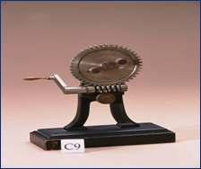
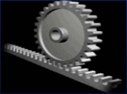
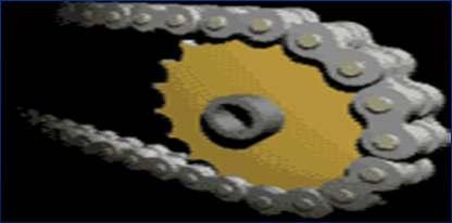
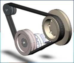
6 Uniform Motion Mechanisms Uniform Motion Equal Displacement For Equal Time Interval Examples : All Gear Drives All Chain Drives Belt Drives without slip

7
8
9
10
11 Non-Uniform Motion Mechanisms Non-Uniform Motion Unequal Displacement For Equal Time Interval Examples : Linkage Mechanisms Cam Mechanisms Geneva Wheel
12
13
14
15 Classification of mechanisms Based on mobility (D.O.F) of the mechanism 1. Considering the D.O.F. of output only a) Constrained Mechanism b) Unconstrained Mechanism 2. Considering the sum of the D.O.F. Of input and output motions a) Single (one) d.o.f. mechanism b) Multi-d.o.f. mechanism
16 Constrained Mechanism One independent output motion. Output member is constrained to move in a particular manner only. Example: Four-bar mechanism Slider Crank Mechanism Five-bar mechanism with two inputs
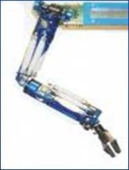
17 Unconstrained mechanism Output motion has more than one D.O.F. Example: Automobile Differential during turning the vehicle on a curve Five-bar mechanism with one input
18 Single D.O.F Mechanism Sum of the input and output D.O.F. is two. Single D.O.F. Motion - One Independent Input motion and one independent output motion Examples : Four-Bar Mechanism Cam-Follower Mechanism
19
20
21 Multi D.O.F. Mechanism Sum of the input and output motion D.O.F. is more than two. Multi D.O.F. Motion More than one Independent Output / Input Motions Examples : Automobile Differential 3-D Cam Mechanism (Camoid) Five-Bar Mechanism
22
23 Classification of Mechanisms Based on position occupied in space Planar Mechanism Spherical Mechanism Spatial Mechanism
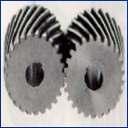
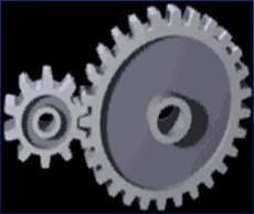
24 Planar Mechanism Planar Motion Particles/Points of Members move in parallel planes Examples : Planar Four-Bar Mechanism Slider Crank Mechanism Cam-Follower Mechanism Spur/Helical Gear Drives

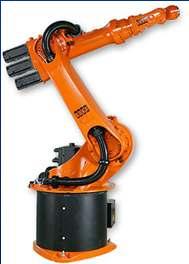
25 Four-bar Crank Rocker and Coupler Curve
26 Two Stroke Engine
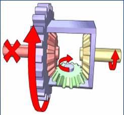
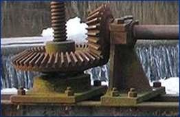
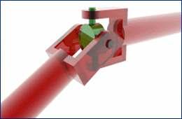
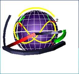
27 Spherical Mechanism Spherical Motion Points maintain Constant Distance w.r.t. a Common Centre Point in any position during motion. Examples : Universal Joint Bevel Gear Drive Spherical Four-Bar Mechanism
28
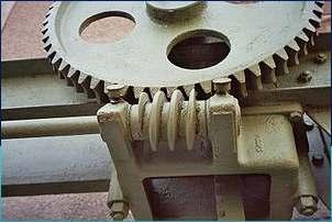
29 Spatial Mechanism Spatial Motion Points can occupy any Position in space Examples : Spatial Four-Bar Mechanism Worm Gear Drive Serial Manipulators

30
31 Classification of mechanisms Based on the connection of the output member Open mechanism Closed mechanism
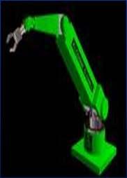
32 Open Mechanism Output member not connected to the fixed link / frame Robot arms Arms of earth movers

33
34 Closed Mechanism Output member connected to the frame. Four-bar mechanism Slider-crank mechanism Cam follower mechanism
35 Components of Mechanisms Link / element Kinematic pairs / joints Kinematic chain


36 Link / Element A single resistant body / combination of resistant bodies having relative motion with another resistant body / combination of resistant bodies. Rigid Body Flexible Body Liquid A


37 Link with one Node : Unary Link Link with two Nodes : Binary Link (a) Link with three Nodes : Ternary Link (b) Link with four Nodes : Quaternary Link (c)
38 Kinematic Pairs / Joints Combination of two links kept in permanent contact permitting particular kind(s) of relative motion(s) between them


39 Classification of Pairs BASED ON NATURE OF CONTACT BETWEEN LINKS: 1. Lower Pairs -- Surface Contact 2. Higher Pairs Point or Line Contact


40 BASED ON HOW THE CONTACT IS MAINTAINED: 1. Self / Form Closed Pairs Shape/Form of the links maintain the contact. No external force. 2. Force Closed Pairs External forces like gravitational force, spring force etc., required to maintain the contact.
41 BASED ON THE DEGREE OF FREEDOM 1. Type I / Class I One D.O.F 2. Type II / Class II Two D.O.F 3. Type III / Class III Three D.O.F 4. Type IV / Class IV Four D.O.F 5. Type V / Class V Five D.O.F BASED ON THE NATURE OF CONSTRAINT 1. (Completely) Constrained Pair - 1 D.O.F 2. Unconstrained Pair More than 1 D.O.F 3. Successfully Constrained pair Unconstrained pair converted as Constrained pair by some means.


42 Completely Constrained Pair Successfully Unconstrained Pair Constrained Pair
43 BASED ON THE POSSIBLE MOTIONS (Few Important Types only) Name of Pair Letter Symbol D.O.F 1. Revolute / Turning Pair R 1 2. Prismatic / Sliding Pair P 1 3. Helical / Screw Pair H 1 4. Cylindrical Pair C 2 5. Spherical / Globular Pair S (or) G 3 6. Flat / Planar Pair E 3 7. Cylindric Plane Pair Cp 4 8. Spheric Plane Pair Sp 5
44
45
46 Kinematic Chain Assembly of links and pairs to produce required / specified output motion(s) for given input motion(s)
47 Mechanism A kinematic chain with one link fixed / stationary
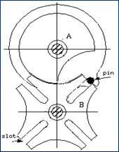
48 Mobility / D.O.F of Mechanism No. of inputs required to get a constrained mechanism (or) no. of position variables needed to sketch the mechanism with all link lengths known. KUTZBACH CRITERION FOR PLANAR MECHANISM F = 3(n-1)-2P 1-1P 2 F D.O.F n No. of links P 1 No. of kinematic pairs with 1 D.O.F. P 2 No. of kinematic pairs with 2 D.O.F.
49
50 DETERMINATION OF D.O.F n = 3 P 1 = 3 P 2 = 0 F=3 x(3 1) 2 x2 1x 0 = = 0 This is a STRUCTURE
51 n = 4 P 1 = 4 P 2 = 0 F = 3x(4 1) 2x4 1x0 = = 1 This is a Constrained Mechanism.
52 n = 5 P 1 = 5 P 2 = 0 F =3 x (5 1) 2x5 1x0 = = 2 This is an Unconstrained Mechanism.
53 n = 6 P 1 = 7 P 2 = 0 F =3 x (6 1) 2x7 1x0 = = 1 This is a Constrained Mechanism.
54 n = 6 P 1 = 7 P 2 = 0 F =3 x (6 1) 2x7 1x0 = = 1 This is a Constrained Mechanism.
55 n = 11 P 1 = 15 P 2 = 0 F =3 x (11 1) 2x15 1x0 = = 0 There are two pairs between Links (2,4,5); (3,4,6); (5,7,8); (8,10,11) This is a Structure.
56 Gruebler s Criterion This criterion is used to find out whether an assembly of links with 1 d.o.f. lower pairs is a constrained mechanism or not. 3n 2l 4 = 0 n no. of links l no.of lower pairs with one d.o.f
57 F < 0 Pre-loaded structure Super structure F = 0 Structure F = 1 Constrained Mechanism F > 1 Unconstrained Mechanism
58 Constrained Mechanism Unconstrained Mechanism
59
60 LINK / ELEMENT KINEMATIC PAIR / JOINT KINEMATIC CHAIN MECHANISM MACHINE
61 Link / Element A resistant body which has relative motion with another resistant body of a system. Kinematic Pair / Joint - Combination / Assembly of two links kept in permanent contact, permitting particular kind(s) of definite relative motion(s) between them. Kinematic Chain Combination / Assembly of links and pairs such that each link has minimum two pairs, permitting controlled definite output motion for a specified input motion. Mechanism A kinematic chain with one link fixed / stationary. Machine A device, which has one or more mechanisms, transferring / transforming motion and energy to do required useful work easily.
62 MOBILITY OR DEGREE OF FREEDOM For a Link Six in spatial motion, three in planar motion. For a Kinematic Pair Number of independent coordinates/pair variables to specify the position of one link with another link (OR) number of independent relative motions possible between the links. Maximum five and minimum one in spatial motion. Maximum two and minimum one in planar motion. For a Kinematic Chain/Mechanism Number of independent position variables to sketch the configuration with known link lengths (OR) number of input motions required to get a constrained output motion

63 Spatial D.O.F. Planar D.O.F. R Pair P Pair C - Pair
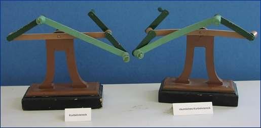
64 Kinematic Inversions Process of obtaining different mechanisms from the same kinematic chain, by fixing different links in turn, is known as kinematic inversion. Four inversions are possible from four-bar kinematic chain.
65 Formation of four-bar mechanism No. of links 4, No. of pairs 4. All the pairs are revolute pairs. Links are :1. Fixed link or Frame 2. Input Link 3. Coupler 4. Output link or Follower
66 Assembly Condition Lengths of links: Longest link - l Shortest link - s Intermediate links p, q l < s + p + q
67 Grashofian four-bar mechanism Atleast one link will have full rotation if S + l p + q
68 GRASHOF S LAW In a planar four bar revolute pair kinematic chain if the sum of the lengths of the shortest and the longest links is less than or equal to the sum of the lengths of the other two intermediate links at least one link will have full rotation. Mechanisms obtained from the kinematic chain satisfying these conditions are known as Grashofian Mechanisms. Mechanisms obtained from the kinematic chain which are not obeying these conditions are known as Non-Grashofian Mechanisms.
69 Inversions of four bar Mechanisms are named based on the motions of input link and output link. Crank - Link with 360 degree rotation Rocker/Lever Link with less than 360 degree rotation
70 Four- bar Inversions Crank Rocker Mechanisms (Two) Drag Link / Double Crank Mechanism Double Rocker Mechanism Above are Grashofian Inversions All four non-grashofian inversions are Double Rocker mechanisms
71 Rockers of Grashofian Mechanisms will have less than 180 degree rotation. Rockers of Non-Grashofian Mechanisms can have greater than 180 degree rotation.
72 KINEMATIC CHAIN One Link Fixed MECHANISM Inversion of the kinematic chain depends upon which link is fixed.
73
74 Conditions for Inversions POSITION OF F0UR BAR INVERSION SHORTEST LINK Adjacent to the fixed link Crank Rocker Fixed link itself Drag Link (Double Crank) Opposite to fixed link Double Rocker


75 Examples for Crank Rocker Mechanism 1. Wind shield wiper mechanism on Driver Side 2. Sewing Machine Treadle Mechanism


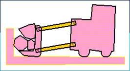
76 3. Grinding Wheel Treadle Mechanism 4. Pedaling action of a Bicycle
77 Example for Double Crank / Drag Link Mechanism Locomotive Wheels Mechanism

78 Example for Double Rocker Mechanism 1. Wind Shield wiper on Passenger Side 2. Ackerman's Steering Gear Mechanism
79
Theory of Machines Course # 1
 Theory of Machines Course # 1 Ayman Nada Assistant Professor Jazan University, KSA. arobust@tedata.net.eg March 29, 2010 ii Sucess is not coming in a day 1 2 Chapter 1 INTRODUCTION 1.1 Introduction Mechanisms
SAMPLE STUDY MATERIAL. Mechanical Engineering. Postal Correspondence Course. Theory of Machines. GATE, IES & PSUs
 TOM - ME GATE, IES, PSU 1 SAMPLE STUDY MATERIAL Mechanical Engineering ME Postal Correspondence Course Theory of Machines GATE, IES & PSUs TOM - ME GATE, IES, PSU 2 C O N T E N T TOPIC 1. MACHANISMS AND
Chapter 4. Mechanism Design and Analysis
 Chapter 4. Mechanism Design and Analysis All mechanical devices containing moving parts are composed of some type of mechanism. A mechanism is a group of links interacting with each other through joints
Chapter 1 Introduction
 Chapter 1 Introduction Generally all considerations in the force analysis of mechanisms, whether static or dynamic, the links are assumed to be rigid. The complexity of the mathematical analysis of mechanisms
Modelling of mechanical system CREATING OF KINEMATIC CHAINS
 Modelling of mechanical system CREATING OF KINEMATIC CHAINS Mechanism Definitions 1. a system or structure of moving parts that performs some function 2. is each system reciprocally joined moveable bodies
Analytical and Applied Kinematics
 Analytical and Applied Kinematics Vito Moreno moreno@engr.uconn.edu 860-614-2365 (cell) http://www.engr.uconn.edu/~moreno Office EB1, hours Thursdays 10:00 to 5:00 1 This course introduces a unified and
ME 321 Kinematics and Dynamics of Machines
 .0 INTRODUCTION ME Kinematics and Dynamics of Machines All Text References in these notes are for: Mechanism Design: Analysis and Synthesis, Volume, Fourth Edition, Erdman, Sandor and Kota, Prentice-Hall,
September 20, Chapter 5. Simple Mechanisms. Mohammad Suliman Abuhaiba, Ph.D., PE
 Chapter 5 Simple Mechanisms 1 Mohammad Suliman Abuhaiba, Ph.D., PE 2 Assignment #1 All questions at the end of chapter 1 st Exam: Saturday 29/9/2018 3 Kinematic Link or Element kinematic link (link) or
Kinematics Fundamentals CREATING OF KINEMATIC CHAINS
 Kinematics Fundamentals CREATING OF KINEMATIC CHAINS Mechanism Definitions 1. a system or structure of moving parts that performs some function 2. is each system reciprocally joined moveable bodies the
Mechanics Place in Science Mechanisms and Structures Number Synthesis Paradoxes and Isomers Transformations and Inversions Grashof s Law
 INTODUCTION TO MECHANISM SYNTHESIS Mechanics Place in Science Mechanisms and Structures Number Synthesis Paradoxes and Isomers Transformations and Inversions Grashof s Law ME312: Dynamics of Mechanisms
SolidWorks Assembly Files. Assemblies Mobility. The Mating Game Mating features. Mechanical Mates Relative rotation about axes
 Assemblies Mobility SolidWorks Assembly Files An assembly file is a collection of parts The first part brought into an assembly file is fixed Other parts are constrained relative to that part (or other
Lecture 3. Planar Kinematics
 Matthew T. Mason Mechanics of Manipulation Outline Where are we? s 1. Foundations and general concepts. 2.. 3. Spherical and spatial kinematics. Readings etc. The text: By now you should have read Chapter
MAE 342 Dynamics of Machines. Types of Mechanisms. type and mobility
 MAE 342 Dynamics of Machines Types of Mechanisms Classification of Mechanisms by type and mobility MAE 342 Dynamics of Machines 2 Planar, Spherical and Spatial Mechanisms Planar Mechanisms: all points
Taibah University Mechanical Engineering
 Instructor: Chapter 2 Kinematics Fundamentals 1. Introduction 2. Degrees of Freedom 3. Types of Motion 4. Links, Joints, and Kinematic Chains 5. Determining Degree of Freedom Degree of Freedom in Planar
WEEKS 1-2 MECHANISMS
 References WEEKS 1-2 MECHANISMS (METU, Department of Mechanical Engineering) Text Book: Mechanisms Web Page: http://www.me.metu.edu.tr/people/eres/me301/in dex.ht Analitik Çözümlü Örneklerle Mekanizma
Mechanism. Mechanism consists of linkages and joints.
 Mechanism Machines are mechanical devices used to accomplish work. A mechanism is a heart of a machine. It is the mechanical portion of the machine that has the function of transferring motion and forces
Kinematics: Intro. Kinematics is study of motion
 Kinematics is study of motion Kinematics: Intro Concerned with mechanisms and how they transfer and transform motion Mechanisms can be machines, skeletons, etc. Important for CG since need to animate complex
Kinematics of Machines. Brown Hills College of Engineering & Technology
 Introduction: mechanism and machines, kinematic links, kinematic pairs, kinematic chains, plane and space mechanism, kinematic inversion, equivalent linkages, four link planar mechanisms, mobility and
2.1 Introduction. 2.2 Degree of Freedom DOF of a rigid body
 Chapter 2 Kinematics 2.1 Introduction 2.2 Degree of Freedom 2.2.1 DOF of a rigid body In order to control and guide the mechanisms to move as we desired, we need to set proper constraints. In order to
Lecture Note 2: Configuration Space
 ECE5463: Introduction to Robotics Lecture Note 2: Configuration Space Prof. Wei Zhang Department of Electrical and Computer Engineering Ohio State University Columbus, Ohio, USA Spring 2018 Lecture 2 (ECE5463
Definitions. Kinematics the study of constrained motion without regard to forces that cause that motion
 Notes_0_0 of efinitions Kinematics the stud of constrained motion without regard to forces that cause that motion namics the stud of how forces cause motion ausalit the relationship between cause and effect
MACHINES AND MECHANISMS
 MACHINES AND MECHANISMS APPLIED KINEMATIC ANALYSIS Fourth Edition David H. Myszka University of Dayton PEARSON ж rentice Hall Pearson Education International Boston Columbus Indianapolis New York San Francisco
Mechanism Synthesis Rules
 Mechanism Synthesis ules Linkage Transformation ules Grashof s Law Inversion ME312: Dynamics of Mechanisms 1 BB LINKAGE TANSFOMATION ULE 1 evolute joints in any loop can be replaced by prismatic joints
Lecture Note 2: Configuration Space
 ECE5463: Introduction to Robotics Lecture Note 2: Configuration Space Prof. Wei Zhang Department of Electrical and Computer Engineering Ohio State University Columbus, Ohio, USA Spring 2018 Lecture 2 (ECE5463
DESIGN AND ANALYSIS OF WEIGHT SHIFT STEERING MECHANISM BASED ON FOUR BAR MECHANISM
 International Journal of Mechanical Engineering and Technology (IJMET) Volume 8, Issue 12, December 2017, pp. 417 424, Article ID: IJMET_08_12_041 Available online at http://www.iaeme.com/ijmet/issues.asp?jtype=ijmet&vtype=8&itype=12
Mechanisms. Updated: 18Apr16 v7
 Mechanisms Updated: 8Apr6 v7 Mechanism Converts input motion or force into a desired output with four combinations of input and output motion Rotational to Oscillating Rotational to Rotational Rotational
Kinematics - Introduction. Robotics. Kinematics - Introduction. Vladimír Smutný
 Kinematics - Introduction Robotics Kinematics - Introduction Vladimír Smutný Center for Machine Perception Czech Institute for Informatics, Robotics, and Cybernetics (CIIRC) Czech Technical University
Computational Design + Fabrication: 4D Analysis
 Computational Design + Fabrication: 4D Analysis Jonathan Bachrach EECS UC Berkeley October 6, 2015 Today 1 News Torque and Work Simple Machines Closed Chains Analysis Paper Review Lab 3 Critique News 2
11. Kinematic models of contact Mechanics of Manipulation
 11. Kinematic models of contact Mechanics of Manipulation Matt Mason matt.mason@cs.cmu.edu http://www.cs.cmu.edu/~mason Carnegie Mellon Lecture 11. Mechanics of Manipulation p.1 Lecture 11. Kinematic models
CHAPTER 1 : KINEMATICS
 KINEMATICS : It relates to the study of the relative motion between the parts of a machine. Let us consider a reciprocating engine, in this the piston is made to reciprocate in the cylinderdue to the applied
[Hasan*, 4.(7): July, 2015] ISSN: (I2OR), Publication Impact Factor: 3.785
![[Hasan*, 4.(7): July, 2015] ISSN: (I2OR), Publication Impact Factor: 3.785](/thumbs/86/93816785.jpg "[Hasan*, 4.(7): July, 2015] ISSN: (I2OR), Publication Impact Factor: 3.785") IJESRT INTERNATIONAL JOURNAL OF ENGINEERING SCIENCES & RESEARCH TECHNOLOGY STUDY OF EPICYCLIC GEAR TRAINS USING GRAPH THEORY Dr. Ali Hasan* * Mech. Engg.Deptt.,Jamia Millia Islamia, New Delhi. ABSTRACT
IJESRT INTERNATIONAL JOURNAL OF ENGINEERING SCIENCES & RESEARCH TECHNOLOGY STUDY OF EPICYCLIC GEAR TRAINS USING GRAPH THEORY Dr. Ali Hasan* * Mech. Engg.Deptt.,Jamia Millia Islamia, New Delhi. ABSTRACT
MECHANICAL ENGINEERING
 MECHANICAL ENGINEERING ESE TOPICWISE OBJECTIVE SOLVED PAPER-II FROM (1995-2018) UPSC Engineering Services Examination State Engineering Service Examination & Public Sector Examination. IES MASTER PUBLICATION
Session #5 2D Mechanisms: Mobility, Kinematic Analysis & Synthesis
 Session #5 2D Mechanisms: Mobility, Kinematic Analysis & Synthesis Courtesy of Design Simulation Technologies, Inc. Used with permission. Dan Frey Today s Agenda Collect assignment #2 Begin mechanisms
1. Introduction 1 2. Mathematical Representation of Robots
 1. Introduction 1 1.1 Introduction 1 1.2 Brief History 1 1.3 Types of Robots 7 1.4 Technology of Robots 9 1.5 Basic Principles in Robotics 12 1.6 Notation 15 1.7 Symbolic Computation and Numerical Analysis
Mechanical Electrical Digital
 Mechatronics I: Mechanical Systems Richard Voyles Week 1 Based on notes from Paul Rullkoetter Mechatronic Systems Mechanical Structure Actuats Senss Transducers DAC ADC Computer Digital Processing Element
2.007 Design and Manufacturing I Spring 2009
 MIT OpenCourseWare http://ocw.mit.edu 2.007 Design and Manufacturing I Spring 2009 For information about citing these materials or our Terms of Use, visit: http://ocw.mit.edu/terms. 2.007 Design and Manufacturing
Robotics Prof. Dilip Kumar Pratihar Department of Mechanical Engineering Indian Institute of Technology, Kharagpur
 Robotics Prof. Dilip Kumar Pratihar Department of Mechanical Engineering Indian Institute of Technology, Kharagpur Lecture 03 Introduction to Robot and Robotics (Contd.) (Refer Slide Time: 00:34) Now,
Lesson 1: Introduction to Pro/MECHANICA Motion
 Lesson 1: Introduction to Pro/MECHANICA Motion 1.1 Overview of the Lesson The purpose of this lesson is to provide you with a brief overview of Pro/MECHANICA Motion, also called Motion in this book. Motion
Kinematics of Machines Prof. A. K. Mallik Department of Mechanical Engineering Indian Institute of Technology, Kanpur. Module - 3 Lecture - 1
 Kinematics of Machines Prof. A. K. Mallik Department of Mechanical Engineering Indian Institute of Technology, Kanpur Module - 3 Lecture - 1 In an earlier lecture, we have already mentioned that there
1.9 Snap Action Mechanisms 19
 Theory of Mechanism and Machines Chapter- Introduction Prepared y rij hooshan sst. Professor. S.. College of Engg. nd Technology Mathura, Uttar Pradesh, (India) Supported y: Purvi hooshan In This Chapter
Overview. What is mechanism? What will I learn today? ME 311: Dynamics of Machines and Mechanisms Lecture 2: Synthesis
 Overview ME 311: Dynamics of Machines and Mechanisms Lecture 2: Synthesis By Suril Shah Some fundamentals Synthesis Function, path and motion generation Limiting condition Dimensional synthesis 1 2 What
 Homework 1 - Grade - ME-3610-001 - Dynamics of Machinery - Tennessee Technologic... Page 1 of 21 My Home Email Calendar Logged in as scanfield 9/26/2011 ME-3610-001 - Dynamics of Machinery Course Home
The hood (3) is linked to the body (1) through two rocker links (2 and 4).
 is linked to the body (1) through two rocker links (2 and 4).") DESIGN OF MACHINERY - th Ed SOLUTION MANUAL -- PROBLEM - Find three (or other number as assigned) of the following common devices. Sketch careful kinematic diagrams and find their total degrees of freedom.
DESIGN OF MACHINERY - th Ed SOLUTION MANUAL -- PROBLEM - Find three (or other number as assigned) of the following common devices. Sketch careful kinematic diagrams and find their total degrees of freedom.
EEE 187: Robotics Summary 2
 1 EEE 187: Robotics Summary 2 09/05/2017 Robotic system components A robotic system has three major components: Actuators: the muscles of the robot Sensors: provide information about the environment and
Kinematics, Kinematics Chains CS 685
 Kinematics, Kinematics Chains CS 685 Previously Representation of rigid body motion Two different interpretations - as transformations between different coord. frames - as operators acting on a rigid body
Kinematics of Machines Prof. A. K. Mallik Department of Mechanical Engineering Indian Institute of Technology, Kanpur. Module - 2 Lecture - 1
 Kinematics of Machines Prof. A. K. Mallik Department of Mechanical Engineering Indian Institute of Technology, Kanpur Module - 2 Lecture - 1 The topic of today s lecture is mobility analysis. By mobility
Kinematic Synthesis. October 6, 2015 Mark Plecnik
 Kinematic Synthesis October 6, 2015 Mark Plecnik Classifying Mechanisms Several dichotomies Serial and Parallel Few DOFS and Many DOFS Planar/Spherical and Spatial Rigid and Compliant Mechanism Trade-offs
A rigid body free to move in a reference frame will, in the general case, have complex motion, which is simultaneously a combination of rotation and
 050389 - Analtical Elements of Mechanisms Introduction. Degrees of Freedom he number of degrees of freedom (DOF) of a sstem is equal to the number of independent parameters (measurements) that are needed
Lecture Note 6: Forward Kinematics
 ECE5463: Introduction to Robotics Lecture Note 6: Forward Kinematics Prof. Wei Zhang Department of Electrical and Computer Engineering Ohio State University Columbus, Ohio, USA Spring 2018 Lecture 6 (ECE5463
Analysis of a 4 Bar Crank-Rocker Mechanism Using COSMOSMotion
 Analysis of a 4 Bar Crank-Rocker Mechanism Using COSMOSMotion ME345: Modeling and Simulation Professor Frank Fisher Stevens Institute of Technology Last updated: June 29th, 2009 Table of Contents 1. Introduction
MACHINE THEORY Bachelor in Mechanical Engineering INTRODUCTION TO MACHINE DESIGN
 MACHINE THEORY Bachelor in Mechanical Engineering INTRODUCTION TO MACHINE DESIGN Ignacio Valiente Blanco José Luis Pérez Díaz David Mauricio Alba Lucero Efrén Díez Jiménez Timm Lauri Berit Sanders Machine
3. Manipulator Kinematics. Division of Electronic Engineering Prof. Jaebyung Park
 3. Manipulator Kinematics Division of Electronic Engineering Prof. Jaebyung Park Introduction Kinematics Kinematics is the science of motion which treats motion without regard to the forces that cause
Robotics. SAAST Robotics Robot Arms
 SAAST Robotics 008 Robot Arms Vijay Kumar Professor of Mechanical Engineering and Applied Mechanics and Professor of Computer and Information Science University of Pennsylvania Topics Types of robot arms
ME 115(b): Final Exam, Spring
: Final Exam, Spring") ME 115(b): Final Exam, Spring 2005-06 Instructions 1. Limit your total time to 5 hours. That is, it is okay to take a break in the middle of the exam if you need to ask me a question, or go to dinner,
ME 115(b): Final Exam, Spring 2005-06 Instructions 1. Limit your total time to 5 hours. That is, it is okay to take a break in the middle of the exam if you need to ask me a question, or go to dinner,
Robotics kinematics and Dynamics
 Robotics kinematics and Dynamics C. Sivakumar Assistant Professor Department of Mechanical Engineering BSA Crescent Institute of Science and Technology 1 Robot kinematics KINEMATICS the analytical study
Industrial Robots : Manipulators, Kinematics, Dynamics
 Industrial Robots : Manipulators, Kinematics, Dynamics z z y x z y x z y y x x In Industrial terms Robot Manipulators The study of robot manipulators involves dealing with the positions and orientations
6. Kinematics of Serial Chain Manipulators
 6. Kinematics of Serial Chain Manipulators 6.1 Assignment of reference frames In a multi-degree-of-freedom mechanical system consisting of rigid bodies, it is useful to attach reference frames to each
Development of Solid Models and Multimedia Presentations of Kinematic Pairs
 Session 2793 Development of Solid Models and Multimedia Presentations of Kinematic Pairs Scott Michael Wharton, Dr. Yesh P. Singh The University of Texas at San Antonio, San Antonio, Texas Abstract Understanding
MEM380 Applied Autonomous Robots Winter Robot Kinematics
 MEM38 Applied Autonomous obots Winter obot Kinematics Coordinate Transformations Motivation Ultimatel, we are interested in the motion of the robot with respect to a global or inertial navigation frame
COPYRIGHTED MATERIAL INTRODUCTION CHAPTER 1
 CHAPTER 1 INTRODUCTION Modern mechanical and aerospace systems are often very complex and consist of many components interconnected by joints and force elements such as springs, dampers, and actuators.
Human Motion. Session Speaker Dr. M. D. Deshpande. AML2506 Biomechanics and Flow Simulation PEMP-AML2506
 AML2506 Biomechanics and Flow Simulation Day 02A Kinematic Concepts for Analyzing Human Motion Session Speaker Dr. M. D. Deshpande 1 Session Objectives At the end of this session the delegate would have
SYNTHESIS OF PLANAR MECHANISMS FOR PICK AND PLACE TASKS WITH GUIDING LOCATIONS
 Proceedings of the ASME 2013 International Design Engineering Technical Conferences and Computers and Information in Engineering Conference IDETC/CIE 2013 August 4-7, 2013, Portland, Oregon, USA DETC2013-12021
Position Analysis
 Position Analysis 2015-03-02 Position REVISION The position of a point in the plane can be defined by the use of a position vector Cartesian coordinates Polar coordinates Each form is directly convertible
Single Actuator Shaker Design to Generate Infinite Spatial Signatures
 2 nd International and 17 th National Conference on Machines and Mechanisms inacomm215-55 Single Actuator Shaker Design to Generate Infinite Spatial Signatures K D Lagoo, T A Dwarakanath and D N Badodkar
INTRODUCTION CHAPTER 1
 CHAPTER 1 INTRODUCTION Modern mechanical and aerospace systems are often very complex and consist of many components interconnected by joints and force elements such as springs, dampers, and actuators.
Week 12 - Lecture Mechanical Event Simulation. ME Introduction to CAD/CAE Tools
 Week 12 - Lecture Mechanical Event Simulation Lecture Topics Mechanical Event Simulation Overview Additional Element Types Joint Component Description General Constraint Refresh Mesh Control Force Estimation
Jane Li. Assistant Professor Mechanical Engineering Department, Robotic Engineering Program Worcester Polytechnic Institute
 Jane Li Assistant Professor Mechanical Engineering Department, Robotic Engineering Program Worcester Polytechnic Institute We know how to describe the transformation of a single rigid object w.r.t. a single
10/11/07 1. Motion Control (wheeled robots) Representing Robot Position ( ) ( ) [ ] T
![10/11/07 1. Motion Control (wheeled robots) Representing Robot Position ( ) ( ) [ ] T](/thumbs/79/79288754.jpg "10/11/07 1. Motion Control (wheeled robots) Representing Robot Position ( ) ( ) [ ] T") 3 3 Motion Control (wheeled robots) Introduction: Mobile Robot Kinematics Requirements for Motion Control Kinematic / dynamic model of the robot Model of the interaction between the wheel and the ground
3 3 Motion Control (wheeled robots) Introduction: Mobile Robot Kinematics Requirements for Motion Control Kinematic / dynamic model of the robot Model of the interaction between the wheel and the ground
Configuration Space. Chapter 2
 Chapter 2 Configuration Space A typical robot is mechanically constructed from several bodies, or links, that are connected by various types of joints. The robot moves when certain joints are driven by
Position and Displacement Analysis
 Position and Displacement Analysis Introduction: In this chapter we introduce the tools to identifying the position of the different points and links in a given mechanism. Recall that for linkages with
Mechanism Kinematics and Dynamics
 Mechanism Kinematics and Dynamics Final Project Presentation 10:10-13:00, 12/21 and 12/28 1. The window shield wiper (2) For the window wiper in Fig.1.33 on p.26 of the PPT, (1). Select the length of all
Robot mechanics and kinematics
 University of Pisa Master of Science in Computer Science Course of Robotics (ROB) A.Y. 2016/17 cecilia.laschi@santannapisa.it http://didawiki.cli.di.unipi.it/doku.php/magistraleinformatica/rob/start Robot
Mechanism Synthesis. Introduction: Design of a slider-crank mechanism
 Mechanism Synthesis Introduction: Mechanism synthesis is the procedure by which upon identification of the desired motion a specific mechanism (synthesis type), and appropriate dimensions of the linkages
MCE/EEC 647/747: Robot Dynamics and Control. Lecture 1: Introduction
 MCE/EEC 647/747: Robot Dynamics and Control Lecture 1: Introduction Reading: SHV Chapter 1 Robotics and Automation Handbook, Chapter 1 Assigned readings from several articles. Cleveland State University
Mobile Robot Kinematics
 Mobile Robot Kinematics Dr. Kurtuluş Erinç Akdoğan kurtuluserinc@cankaya.edu.tr INTRODUCTION Kinematics is the most basic study of how mechanical systems behave required to design to control Manipulator
MECHANICS OF MACHINERY
 MECHNICS OF MCHINERY (For B.E. Mechanical Engineering Students) s per New Revised Syllabus of PJ bdul Kalam Technological University Dr. S. Ramachandran, M.E., Ph.D., Dr..G. Mathew, PhD (NIT-Durgapur)
Kinematics of Machines Prof. A. K. Mallik Department of Mechanical Engineering Indian Institute of Technology, Kanpur. Module 10 Lecture 1
 Kinematics of Machines Prof. A. K. Mallik Department of Mechanical Engineering Indian Institute of Technology, Kanpur Module 10 Lecture 1 So far, in this course we have discussed planar linkages, which
Using RecurDyn. Contents
 Using RecurDyn Contents 1.0 Multibody Dynamics Overview... 2 2.0 Multibody Dynamics Applications... 3 3.0 What is RecurDyn and how is it different?... 4 4.0 Types of RecurDyn Analysis... 5 5.0 MBD Simulation
OPTIMAL KINEMATIC DESIGN OF A CAR AXLE GUIDING MECHANISM IN MBS SOFTWARE ENVIRONMENT
 OPTIMAL KINEMATIC DESIGN OF A CAR AXLE GUIDING MECHANISM IN MBS SOFTWARE ENVIRONMENT Dr. eng. Cătălin ALEXANDRU Transilvania University of Braşov, calex@unitbv.ro Abstract: This work deals with the optimal
Mechanism Simulation With Working Model
 Mechanism Simulation With Working Model Shih-Liang Wang Department of Mechanical Engineering North Carolina A&T State University Greensboro, NC 27411 Introduction Kinematics is a study of motion and force
Chapter 5 Modeling and Simulation of Mechanism
 Chapter 5 Modeling and Simulation of Mechanism In the present study, KED analysis of four bar planar mechanism using MATLAB program and ANSYS software has been carried out. The analysis has also been carried
Mechanism Kinematics and Dynamics
 Mechanism Kinematics and Dynamics Final Project 1. The window shield wiper For the window wiper, (1). Select the length of all links such that the wiper tip X p (t) can cover a 120 cm window width. (2).
MEAM 520. Manipulator Kinematics
 MEAM 520 Manipulator Kinematics Katherine J. Kuchenbecker, Ph.D. General Robotics, Automation, Sensing, and Perception Lab (GRASP) MEAM Department, SEAS, University of Pennsylvania Lecture 4: September
Kinematics. Kinematics analyzes the geometry of a manipulator, robot or machine motion. The essential concept is a position.
 Kinematics Kinematics analyzes the geometry of a manipulator, robot or machine motion. The essential concept is a position. 1/31 Statics deals with the forces and moments which are aplied on the mechanism
DOUBLE CIRCULAR-TRIANGULAR SIX-DEGREES-OF- FREEDOM PARALLEL ROBOT
 DOUBLE CIRCULAR-TRIANGULAR SIX-DEGREES-OF- FREEDOM PARALLEL ROBOT V. BRODSKY, D. GLOZMAN AND M. SHOHAM Department of Mechanical Engineering Technion-Israel Institute of Technology Haifa, 32000 Israel E-mail:
KINEMATICS OF AN OVERCONSTRAINED MECHANISM IN PRACTICE
 KINEMTICS OF N OVERCONSTRINED MECHNISM IN PRCTICE Vandan Kamlakar Gundale* bstract: In 1939 Paul Schatz, a Swiss anthroposophist and geometrician had invented a mechanism which with few links generates
Kinematics of Closed Chains
 Chapter 7 Kinematics of Closed Chains Any kinematic chain that contains one or more loops is called a closed chain. Several examples of closed chains were encountered in Chapter 2, from the planar four-bar
BND TechSource. Ergonomic Manikin Manipulation using CATIA V5 DMU Kinematics. (Steps 5-11 the optimized solution)
") Ergonomic Manikin Manipulation using CATIA V5 DMU Kinematics (Steps 5-11 the optimized solution) In the previous example, we showed a simple solution to manipulate an Ergonomic Manikin using CATIA DMU
Ergonomic Manikin Manipulation using CATIA V5 DMU Kinematics (Steps 5-11 the optimized solution) In the previous example, we showed a simple solution to manipulate an Ergonomic Manikin using CATIA DMU
3. Planar kinematics Mechanics of Manipulation
 3. Planar kinematics Mechanics of Manipulation Matt Mason matt.mason@cs.cmu.edu http://www.cs.cmu.edu/~mason Carnegie Mellon Lecture 3. Mechanics of Manipulation p.1 Lecture 2. Planar kinematics. Chapter
Robot mechanics and kinematics
 University of Pisa Master of Science in Computer Science Course of Robotics (ROB) A.Y. 2017/18 cecilia.laschi@santannapisa.it http://didawiki.cli.di.unipi.it/doku.php/magistraleinformatica/rob/start Robot
MCE/EEC 647/747: Robot Dynamics and Control. Lecture 3: Forward and Inverse Kinematics
 MCE/EEC 647/747: Robot Dynamics and Control Lecture 3: Forward and Inverse Kinematics Denavit-Hartenberg Convention Reading: SHV Chapter 3 Mechanical Engineering Hanz Richter, PhD MCE503 p.1/12 Aims of
Mechanism and Robot Kinematics, Part I: Algebraic Foundations
 Mechanism and Robot Kinematics, Part I: Algebraic Foundations Charles Wampler General Motors R&D Center In collaboration with Andrew Sommese University of Notre Dame Overview Why kinematics is (mostly)
AC : AN ALTERNATIVE APPROACH FOR TEACHING MULTIBODY DYNAMICS
 AC 2009-575: AN ALTERNATIVE APPROACH FOR TEACHING MULTIBODY DYNAMICS George Sutherland, Rochester Institute of Technology DR. GEORGE H. SUTHERLAND is a professor in the Manufacturing & Mechanical Engineering
Chapter 4 Dynamics. Part Constrained Kinematics and Dynamics. Mobile Robotics - Prof Alonzo Kelly, CMU RI
 Chapter 4 Dynamics Part 2 4.3 Constrained Kinematics and Dynamics 1 Outline 4.3 Constrained Kinematics and Dynamics 4.3.1 Constraints of Disallowed Direction 4.3.2 Constraints of Rolling without Slipping
ME 115(b): Final Exam, Spring
: Final Exam, Spring") ME 115(b): Final Exam, Spring 2011-12 Instructions 1. Limit your total time to 5 hours. That is, it is okay to take a break in the middle of the exam if you need to ask me a question, or go to dinner,
ME 115(b): Final Exam, Spring 2011-12 Instructions 1. Limit your total time to 5 hours. That is, it is okay to take a break in the middle of the exam if you need to ask me a question, or go to dinner,
https://www.youtube.com/watch?v=qeb2yxmqogi
 Name _Greg Brulo https://www.youtube.com/watch?v=qeb2yxmqogi Scissor Jack The scissor jack is a popular jack found in a vehicles flat tire kit. The operator cranks the input rod to raise and lower the
Robot Geometry and Kinematics
 CIS 68/MEAM 50 Robot Geometr and Kinematics CIS 68/MEAM 50 Outline Industrial (conventional) robot arms Basic definitions for understanding -D geometr, kinematics Eamples Classification b geometr Relationship
Motion Control (wheeled robots)
") Motion Control (wheeled robots) Requirements for Motion Control Kinematic / dynamic model of the robot Model of the interaction between the wheel and the ground Definition of required motion -> speed control,
Motion Control (wheeled robots) Requirements for Motion Control Kinematic / dynamic model of the robot Model of the interaction between the wheel and the ground Definition of required motion -> speed control,
Spatial R-C-C-R Mechanism for a Single DOF Gripper
 NaCoMM-2009-ASMRL28 Spatial R-C-C-R Mechanism for a Single DOF Gripper Rajeev Lochana C.G * Mechanical Engineering Department Indian Institute of Technology Delhi, New Delhi, India * Email: rajeev@ar-cad.com
The Design and Simulation of Mechanisms. Inna Sharifgalieva
 The Design and Simulation of Mechanisms Inna Sharifgalieva Degree Thesis Degree Programme: Materials Processing Technology 2014 2018 1 DEGREE THESIS Arcada University of Applied Sciences Degree Programme: