LMS Virtual.Lab The Unified Environment for Functional Performance Engineering
|
|
|
- Arlene Nash
- 6 years ago
- Views:
Transcription


1 LMS Virtual.Lab The Unified Environment for Functional Performance Engineering LMS Imagine.Lab LMS OPTIMUS LMS Engineering and Deployment Services Technology Transfer Process Transformation & Best Practices System Support LMS SCADAS Mobile - Lab LMS Test.Lab LMS Tec.Manager LMS Virtual.Lab Motion, NVH, Acostics, Optimization 1 copyright LMS International
2 Strategy and Assumptions CAD Data could have come from UGS, Pro-E, Solidworks, Autodesk, Parasolids Interface with all FEA Tools, ABAQUS, NASTRAN, ANSYS, UGS - NX, PERMAS, or CATIA GPS Modeled using a Scalable Approach without having to switch between different products. Reasonably accurate results for early trade off studies vs. high accuracy for test correlation Provide option to choose between Medium Fidelity / Fast Solution vs. High Fidelity / Accuracy Leverage capabilities of the Virtual Lab Framework, Knowledgeware, Design Tables, Parameterization etc. Highlight the techniques that can be used with Virtual Lab for support of a typical Preliminary Design Decision Process. 2 copyright LMS International

 Design of Oleo System 1-D Representation of Landing")


3 Process Flow Drop Test Tool for modeling and simulation of multi-disciplinary systems (hydraulic, pneumatic, thermal, mechanical, controls, etc.) Design of Oleo System 1-D Representation of Landing Gear Reuse AMESim Oleo System Model LMS Virtual.Lab Motion LMS Virtual.Lab Motion Auto Flex Tool for 3-D Multi Body system design Validate Oleo system with 3-D Landing Gear Model and Flexible Modeling for Critical Components 3 copyright LMS International Tool for FEA of Components Provides Craig-Bampton modes for Flexible Bodies


4 Drop Test Model Oleo Dynamics Starting Point : 1D AMESim Model of Landing Gear Initial Design of Oleo Damping Validation: 1D AMESim Model Oleo Hydraulics Reused by 3-D Motion Drop Test Simulation Motion/Plant AMESim Coupled Equations Motion Solver Integrates both sets of Equations 4 copyright LMS International
5 Drop Test Model Tire & Lift Forces Tire Forces Calculates & Applies forces at the tire contact patch between ground and wheel body in up to 3 directions when in contact Choice of tire model typically a trade off Level of accuracy required Amount of test data available Desired run times Full library of tire forces available in Virtual.Lab Motion Simple Tire LMS Durability Tire TNO Swift Tire Standard Tire Interface ( User Defined Tire) z w eff β eff belt r eff eff. road plane F z SWIFT model structure Ω wheel rim V F x ϕ -ψ. C residual springs actual road surface γ ϕ* wheel plane belt _ V c α _ V * α* M z F y Based on data provided & goals of the process, Simple Tire force was used Lift Force 3 Point force applied to aircraft in global z direction equal to total weight of aircraft + gear Aircraft weight is parameter to this force pac copyright LMS International

6 Drop Test Model Contact Forces Large gaps present in Lug Drag & Side Braces Virtual.Lab motion Contact forces used to simulate these gaps Based on Hertzian formulation, very stable, fast & accurate Added to drop test model but required for Stress analysis portion 6 copyright LMS International

7 Drop Test Model - Flexibility FEA required to calculate mode shapes as input Tough choice about which FEA solver to use Virtual.Lab Motion is compatible with a number of different solvers Can reuse models between Drop Test & Stress Analysis with any of these solvers Craig-Bampton mode set drivers available CATIA GPS chosen because of Auto Flex capability Easiest setup of Flexible Bodies Fully Associative with geometry Select Rigid Body in mechanism model the Mesh & FE load cases are automatically defined 2 nd Craig-Bamption mode 106Hz 7 copyright LMS International


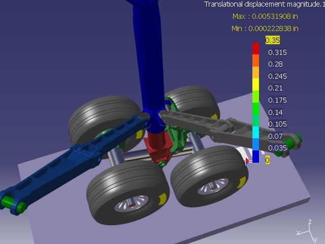
8 Drop Test Results 8 copyright LMS International

9 Drop Test Load Stroke curves Load - pounds Stroke - inches 9 copyright LMS International
10 Process Flow Stress Analysis LMS Virtual.Lab Motion Reuse Flexible Drop Test model to generate BC for stress analysis Design Tables & Configurations used to control model Geometrically non-linear solution LMS Virtual.Lab Optimization Tool for DOE, Optimization, Reliability and Robust Design Used to calculate geometric sizing to achieve target stress Automatic component load transfer to CSA LMS Virtual.Lab Motion Auto Flex Tool for FEA of components Multiple FEA solvers available to Virtual.Lab 10 copyright LMS International


11 Stress Analysis Boundary Conditions & Load Transfer Demonstrates how Virtual.Lab Motion models can be used to generate boundary conditions for FEA Braking & Turning Analysis cases added to Drop Test model s specification tree Differences in topology controlled by Design Tables & Configurations Virtual.Lab Motion Contact forces used to simulate gaps in Lug Side & Drag brace connections Outer Cylinder was flexible, other bodies rigid Side & Drag braces roughly the same size Problem thought of as being statically determinate Majority of compliance assumed to be in Contact forces between Lug Side & Drag braces Automatic load transfer in Motion transfers and sets up Static Analysis cases for CSA at any time step(s) LMS Virtual.Lab Motion Auto Flex LMS Virtual.Lab Motion 11 copyright LMS International


12 Stress Analysis Virtual Lab CSA ( CATIA GPS) User choice for which FEA solver to use Virtual.Lab is compatible and scalable with a number of different solvers Same model used for Flexible bodies can be used for stress analysis CSA had some advantages for this choice of process Virtual Lab embedded, designer friendly FEA tool Auto flex & Load transfer capability with Virtual.Lab Motion Best fit for the goals we established for this process Parabolic tetrahedron elements used Global mesh size 2in, local mesh size.25in 12 copyright LMS International


13 Stress Analysis Virtual.Lab Optimization Virtual.Lab Optimization obvious choice for calculating geometric sizing to achieve target stresses One integrated approach to optimization for all Virtual.Lab Full accessibility to Virtual.Lab parameterization (Knowledgeware) Applicable to any Workflow captured in Virtual.Lab. 1 pad and 2 fillets added to part Engineering judgment & basic solid modeling skill required Dimensions of these features input to Optimization Max Principal stress for both load cases calculated by CSA Objective Determine sizing to achieve Max Stress < 120ksi 13 copyright LMS International

14 Stress Analysis Results Starting Point: Outer Fillet Radius = 0.5in Max Principal Stress = ksi Optimization Result: Outer Fillet Radius ~ 2.25in Max Principal Stress = ksi 14 copyright LMS International


15 Process Flow Stress Analysis & Torque Link Optimization LMS Virtual.Lab Geometry Advanced Geometric Wireframe, Surface & Sold Geometric modeler Parameterized Length of Torque Link LMS Virtual.Lab Structures Tool for FEA of components & assemblies Multiple FEA solvers available to Virtual.Lab LMS Virtual.Lab Optimization Tool for DOE, Optimization, Reliability and Robust Design Used to calculate geometric sizing to achieve targets FEA Solver FEA Solver Any Solver that supports Analysis Objectives 15 copyright LMS International


16 Torque Link Optimization Torque Link geometry modified so that length was driving parameter CAD Assembly was meshed using Virtual.Lab Structures Gap Connectors used to simulate complex load paths Virtual.Lab compatible with a number of different FEA Solvers Virtual.Lab Optimization used to determine optimum Torque Link Length Torque Link Length was input Goal was to minimize mass Maximum Principal Stress was bound on Optimization Braking Stress Before Steering Optimization Stress Before Optimization 16 copyright LMS International Setting Up Optimization Braking Stress After Optimization Steering Stress After Optimization
Multi-Disciplinary Design of an Aircraft Landing Gear with Altair HyperWorks
 Multi-Disciplinary Design of an Aircraft Landing Gear with Altair HyperWorks Altair Engineering, October 2008 Introduction Task: To design an aircraft landing gear that meets design requirements of several
Leveraging Integrated Concurrent Engineering for vehicle dynamics simulation. Manuel CHENE MSC.Software France
 Leveraging Integrated Concurrent Engineering for vehicle dynamics simulation Manuel CHENE MSC.Software France Agenda Challenge of vehicle dynamic simulation: frequency domain coverage necessity for a multi
LMS Virtual.Lab Motion Desktop
 Answers for industry LMS Virtual.Lab Motion Desktop [VL-MOT.80.1] 13.1 Benefits Gain insight in the kinematic and dynamic performance of a mechanism Increase product quality by efficient full system optimization
Simcenter 3D Engineering Desktop
 Simcenter 3D Engineering Desktop Integrating geometry and FE modeling to streamline the product development process Benefits Speed simulation processes by up to 70 percent Increase product quality by rapidly
Simcenter Motion 3D. Mechatronics - Improve Design Dynamics Performance: Combine 3D Multi-Body Simulation with 1D Actuation & Controls Simulation
 Simcenter Motion 3D Mechatronics - Improve Design Dynamics Performance: Combine 3D Multi-Body Simulation with 1D Actuation & Controls Simulation Iurie TERNA Email: iurie.terna@siemens.com Tuesday 16:00-17:00
Using RecurDyn. Contents
 Using RecurDyn Contents 1.0 Multibody Dynamics Overview... 2 2.0 Multibody Dynamics Applications... 3 3.0 What is RecurDyn and how is it different?... 4 4.0 Types of RecurDyn Analysis... 5 5.0 MBD Simulation
Simcenter 3D Engineering Desktop
 Simcenter 3D Engineering Desktop Integrating geometry and FE modeling to streamline the product development process Benefits Speed simulation processes by up to 70 percent Increase product quality by rapidly
Fundamentals of Modeling with Simcenter 3D Robin Boeykens
 Fundamentals of Modeling with Simcenter 3D Robin Boeykens robin.boeykens@siemens.com Realize innovation. 3D CAE for the digital twin Simcenter 3D Page 2 Simcenter 3D Engineering Desktop Simcenter 3D Engineering
Group 5 James Pacey, Ray Brown, Brent Sutherland
 Group 5 James Pacey, Ray Brown, Brent Sutherland Definition: To model a constant velocity birfield axle joint and shaft, and perform a stress analysis on the birfield Objectives: Gain further CAD experience
MAE 323: Lab 7. Instructions. Pressure Vessel Alex Grishin MAE 323 Lab Instructions 1
 Instructions MAE 323 Lab Instructions 1 Problem Definition Determine how different element types perform for modeling a cylindrical pressure vessel over a wide range of r/t ratios, and how the hoop stress
Simcenter 3D Structures
 Simcenter 3D Structures Integrating FE modeling and simulation streamlines product development Benefits Speed simulation processes by up to 70 percent Perform accurate, reliable structural analysis with
imaginit.com/simulation Complete and robust mechanical simulation solution
 imaginit.com/simulation Complete and robust mechanical simulation solution A mechanical simulation solution for finite imaginit.com/simulation element analysis powered by the Autodesk Nastran solver Accurately
GEOMETRY-BASED VIRTUAL MODEL VARIANTS FOR SHAPE OPTIMIZATION AND CAD REFEED
 GEOMETRY-BASED VIRTUAL MODEL VARIANTS FOR SHAPE OPTIMIZATION AND CAD REFEED *Dr. Werner Pohl, ** Prof. Dr. Klemens Rother *Fast Concept Modelling & Simulation (FCMS) GmbH, Munich, Germany, **University
Modal Analysis of Exhaust System to Optimize Mounting Hanger Location
 Modal Analysis of Exhaust System to Optimize Mounting Hanger Location Chetan D. Gaonkar Assistant Professor, Mechanical Engineering Dpt., DBCE, Margao, Goa Abstract An exhaust system with a superior performance
LMS Virtual.Lab Correlation
 LMS Virtual.Lab Correlation LMS Virtual.Lab Correlation Systematic validation from the bottom up 2 LMS Virtual.Lab Correlation LMS Virtual.Lab Correlation 3 LMS Virtual.Lab Correlation Systematic validation
Appendix P. Multi-Physics Simulation Technology in NX. Christian Ruel (Maya Htt, Canada)
") 251 Appendix P Multi-Physics Simulation Technology in NX Christian Ruel (Maya Htt, Canada) 252 Multi-Physics Simulation Technology in NX Abstract As engineers increasingly rely on simulation models within
251 Appendix P Multi-Physics Simulation Technology in NX Christian Ruel (Maya Htt, Canada) 252 Multi-Physics Simulation Technology in NX Abstract As engineers increasingly rely on simulation models within
SimLab Release Notes. 1 A l t a i r E n g i n e e r i n g
 SimLab 11.0 Release Notes 1 A l t a i r E n g i n e e r i n g System Support extended to load and save GDA/SLB files of size greater than 4GB. Memory allocation is enhanced to support large models. Kubrix
midas NFX An insight into midas NFX
 midas NFX An insight into midas NFX Total Analysis Solutions for Multi-disciplinary Optimum Design Part 1. Work environment Multi-disciplinary CAE solutions in one unique work environment 1 Part 1. Work
NX Advanced FEM. fact sheet
 Advanced FEM fact sheet www.ugs.com Summary Advanced FEM is a comprehensive multi-cad finite element modeling and results visualization product that is designed to meet the needs of experienced CAE analysts.
Overcoming Data Translation Issues Using SimDesigner Enterprise Gateway
 Overcoming Data Translation Issues Using SimDesigner Enterprise Gateway Van N. Eidom Engineer Specialist Aircraft Braking Systems Corporation Introduction This presentation demonstrates how the SimDesigner
Industrial finite element analysis: Evolution and current challenges. Keynote presentation at NAFEMS World Congress Crete, Greece June 16-19, 2009
 Industrial finite element analysis: Evolution and current challenges Keynote presentation at NAFEMS World Congress Crete, Greece June 16-19, 2009 Dr. Chief Numerical Analyst Office of Architecture and
SimLab 14.1 Release Notes
 SimLab 14.1 Release Notes Highlights SimLab 14.0 introduced the new user interface. SimLab 14.1 enhances the user interface using feedback from customers. In addition many new core features have been added.
PTC Newsletter January 14th, 2002
 PTC Email Newsletter January 14th, 2002 PTC Product Focus: Pro/MECHANICA (Structure) Tip of the Week: Creating and using Rigid Connections Upcoming Events and Training Class Schedules PTC Product Focus:
3. Preprocessing of ABAQUS/CAE
 3.1 Create new model database 3. Preprocessing of ABAQUS/CAE A finite element analysis in ABAQUS/CAE starts from create new model database in the toolbar. Then save it with a name user defined. To build
NX Advanced Simulation
 Siemens PLM Software Integrating FE modeling and simulation streamlines product development process Benefits Speed simulation processes by up to 70 percent Perform accurate, reliable structural analysis
Complete and robust mechanical simulation solution. imaginit.com/simulation-mechanical
 Complete and robust mechanical simulation solution A mechanical simulation solution for finite element analysis powered by the Autodesk Nastran solver Accurately predict product behavior, optimize and
STRENGTH RELIABILITY OF TURBINE ROTOR ENSURING BASED ON MULTIDISCIPLINARY OPTIMIZATION Salnikov Anton* *CIAM
 STRENGTH RELIABILITY OF TURBINE ROTOR ENSURING BASED ON MULTIDISCIPLINARY OPTIMIZATION Salnikov Anton* *CIAM salnikov@ciam.ru Keywords: rotor, HPT, optimization, disk, root connection, fir-tree-type Abstract
NX Advanced FEM. Benefits
 Advanced FEM fact sheet Siemens PLM Software www.siemens.com/plm Summary Advanced FEM software is a comprehensive multi-cad finite element modeling and results visualization product that is designed to
SimWise 4D. Integrated Motion and Stress Analysis
 SimWise 4D Integrated Motion and Stress Analysis SimWise 4D Integrated Motion Simulation and Stress Analysis SimWise 4D is a software tool that allows the functional performance of mechanical parts and
Introduction to ANSYS
 Lecture 1 Introduction to ANSYS ICEM CFD 14. 0 Release Introduction to ANSYS ICEM CFD 1 2011 ANSYS, Inc. March 22, 2015 Purpose/Goals Ansys ICEM CFD is a general purpose grid generating program Grids for
Ansys Mechanical APDL
 Ansys Mechanical APDL Day 1: FEA and ANSYS 9.00 12.00 About ANSYS, What is FEA?, Instructor Example Getting Started 12.00 1.00 Interactive Vs. Batch Mode, Starting ANSYS, Product Launcher, ANSYS Workbench,
SIMPACKS s FEA Interface New Features in 8.5 and Further Development. Stefan Dietz, INTEC GmbH
 SIMPACKS s FEA Interface New Features in 8.5 and Further Development Stefan Dietz, INTEC GmbH Contents New Features in 8.5 integration into SIMPACK GUI generalised file interface between FE-codes and SIMPACK
Application to Vehicles Dynamics. Taking into account local non linearity in MBS models. This document is the property of SAMTECH S.A.
 Application to Vehicles Dynamics Taking into account local non linearity in MBS models This document is the property of SAMTECH S.A. Page 1 Tables of contents Introduction SAMTECH Expertise SAMTECH Methodology
Introduction to ANSYS ICEM CFD
 Lecture 1 Introduction to ANSYS ICEM CFD 14.5 Release Introduction to ANSYS ICEM CFD 2012 ANSYS, Inc. April 1, 2013 1 Release 14.5 Purpose/Goals Ansys ICEM CFD is a general purpose grid generating program
Training Course Content
 Pioneering engineering software systems, support & services. Training Course Content 29800 Middlebelt Road Suite 100 Farmington Hills, MI 48334 United States of America Tel: +1 248 737 9760 Fax: +1 248
SOLIDWORKS Simulation
 SOLIDWORKS Simulation Length: 3 days Prerequisite: SOLIDWORKS Essentials Description: SOLIDWORKS Simulation is designed to make SOLIDWORKS users more productive with the SOLIDWORKS Simulation Bundle. This
--Niju Nair, Account manager
 The content in this document is for viewing only. Reproduction in any form is not permissible. --Niju Nair, Account manager Contents - Possible solutions for the engineering & Optimization challenges.
Efficient Shape Optimisation of an Aircraft Landing Gear Door Locking Mechanism by Coupling Abaqus to GENESIS
 Efficient Shape Optimisation of an Aircraft Landing Gear Door Locking Mechanism by Coupling Abaqus to GENESIS Mark Arnold and Martin Gambling Penso Consulting Ltd GRM Consulting Ltd Abstract: The objective
What s new in Femap 9.3
 What s new in Femap 9.3 fact sheet www.ugs.com/femap Summary Femap version 9.3 is the latest release of UGS robust pre and post processor for engineering finite element analysis (FEA). Femap software is
ANSYS - Workbench Overview. From zero to results. AGH 2014 April, 2014 W0-1
 ANSYS - Workbench Overview From zero to results 2014 W0-1 Runing ANSYS WEiP ANSYS We are going to work in most advanced ANSYS Workbench W0-2 ANSYS Workbench WEiP What is Workbench? Platform for integration
Multi-Objective Optimization of a Boomerang Shape using modefrontier and STAR-CCM+
 Multi-Objective Optimization of a Boomerang Shape using modefrontier and STAR-CCM+ Alberto Clarich*, Rosario Russo ESTECO, Trieste, (Italy) Enrico Nobile, Carlo Poloni University of Trieste (Italy) Summary
Geometric Modeling Systems
 Geometric Modeling Systems Wireframe Modeling use lines/curves and points for 2D or 3D largely replaced by surface and solid models Surface Modeling wireframe information plus surface definitions supports
Model Library Mechanics
 Model Library Mechanics Using the libraries Mechanics 1D (Linear), Mechanics 1D (Rotary), Modal System incl. ANSYS interface, and MBS Mechanics (3D) incl. CAD import via STL and the additional options
Информационные системы и технологии
 42 Электроника и связь 1 2012 Информационные системы и технологии UDC 531.36; 534.1 A.P. Timohin 1, D.I. Konotop 2, V.P. Zinchenko 2, Ph. D. Providing tire stiffness tests in LMS Virtual.Lab-Imagine.Lab
RHEOMOLD ENGINEERING SOLUTIONS LLP
 RHEOMOLD ENGINEERING SOLUTIONS LLP 1 Content Rheomold Services & Capabilities Rheomold Capacity Design Projects executed CAE Projects executed Manufacturing Simulations (Moldflow, Casting & Forming) Customers
Andy Haines, Applications Engineer - Principal Siemens PLM Software
 Efficient Modification of Mesh-Centric Finite Element Models with Femap Simcenter User Connection Tuesday, May 09, 2017/2:30 PM-3:15 PM Andy Haines, Applications Engineer - Principal Brought to you by:
SIMPACK - A Tool for Off-Line and Real- Time Simulation
 SIMPACK - A Tool for Off-Line and Real- Time Simulation Real-Time for ECU Testing: State of the Art and Open Demands SIMPACK - Code Export: A Newly Emerging Module for Real-Time Models Application Example
Lab 9: Importing CAD Geometry
 Page 1 Lab 9: Importing CAD Geometry Objective This lab will explain 2 methods that can be used to import CAD geometry from a CATIA V4 Model. The first method assumes all of the V4 Geometric and Kinematic
pre- & post-processing f o r p o w e r t r a i n
 pre- & post-processing f o r p o w e r t r a i n www.beta-cae.com With its complete solutions for meshing, assembly, contacts definition and boundary conditions setup, ANSA becomes the most efficient and
Femap automatic meshing simplifies virtual testing of even the toughest assignments
 Femap automatic meshing simplifies virtual testing of even the toughest assignments fact sheet Siemens PLM Software www.siemens.com/plm/femap Summary Femap version 10 software is the latest release of
SimLab 14.2 Release Notes
 SimLab 14.2 Release Notes Highlights SimLab 14.2 comes with various changes that improve performance and graphics rendering. In addition to java scripting, python scripting is introduced. The enhancements,
LMS Virtual.Lab Boundary Elements Acoustics
 Answers for industry LMS Virtual.Lab Boundary Elements Acoustics [VL-VAM.35.2] 13.1 Benefits Accurate modelling of infinite domain acoustic problems Fast and efficient solvers Modeling effort is limited
MSC.visualNastran Desktop FEA Exercise Workbook. Pin and Bracket Assembly: Vibration Simulation in 4D
 MSC.visualNastran Desktop FEA Exercise Workbook Pin and Bracket Assembly: Vibration Simulation in 4D WS24-2 Objectives This exercise is design to introduce vibration analysis in visualnastran Desktop.
Program: Advanced Certificate Program
 Program: Advanced Certificate Program Course: CFD-Vehicle Aerodynamics Directorate of Training and Lifelong Learning #470-P, Peenya Industrial Area, 4th Phase Peenya, Bengaluru 560 058 www.msruas.ac.in
Integrated Multi-Disciplinary Dynamics
 Integrated Multi-Disciplinary Dynamics Concept of RecurDyn Communicators Free input and output High Performance Interface for CAE Eigen-Solver Large Problem Solver Multi-CPU Solver MBD/FEA(MFBD) General
Topology Optimization for Designers
 TM Topology Optimization for Designers Siemens AG 2016 Realize innovation. Topology Optimization for Designers Product Features Uses a different approach than traditional Topology Optimization solutions.
Finite Element Analysis Using Creo Simulate 4.0
 Introduction to Finite Element Analysis Using Creo Simulate 4.0 Randy H. Shih SDC PUBLICATIONS Better Textbooks. Lower Prices. www.sdcpublications.com Powered by TCPDF (www.tcpdf.org) Visit the following
ME 475 Modal Analysis and Optimization of a Tapered Beam
 ME 475 Modal Analysis and Optimization of a Tapered Beam Objectives: To optimize the shape of a tapered beam to minimize the mass, while holding the first three natural frequencies above those of the baseline
Introduction to FEM Modeling
 Total Analysis Solution for Multi-disciplinary Optimum Design Apoorv Sharma midas NFX CAE Consultant 1 1. Introduction 2. Element Types 3. Sample Exercise: 1D Modeling 4. Meshing Tools 5. Loads and Boundary
FTire. The Market-Leading Physics-Based Tire Model.
 FTire The Market-Leading Physics-Based Tire Model www.cosin.eu FTire - The Flexible Structure Tire Model FTire is a highly accurate physics-based, 3D nonlinear tire simulation model developed by cosin
Directions: 1) Delete this text box 2) Insert desired picture here
 Delete this text box 2) Insert desired picture here") Directions: 1) Delete this text box 2) Insert desired picture here Multi-Disciplinary Applications using Overset Grid Technology in STAR-CCM+ CD-adapco Dmitry Pinaev, Frank Schäfer, Eberhard Schreck Outline
Directions: 1) Delete this text box 2) Insert desired picture here Multi-Disciplinary Applications using Overset Grid Technology in STAR-CCM+ CD-adapco Dmitry Pinaev, Frank Schäfer, Eberhard Schreck Outline
Introduction to Finite Element Analysis using ANSYS
 Introduction to Finite Element Analysis using ANSYS Sasi Kumar Tippabhotla PhD Candidate Xtreme Photovoltaics (XPV) Lab EPD, SUTD Disclaimer: The material and simulations (using Ansys student version)
30 th Anniversary Event. New features in Opera By Nigel Atkinson, PhD. OPTIMIZER Automatically selects and manages multiple goalseeking
 FEA ANALYSIS General-purpose multiphysics design and analysis software for a wide range of applications OPTIMIZER Automatically selects and manages multiple goalseeking algorithms INTEROPERABILITY Built-in
FEA and Topology Optimization of an Engine Mounting Bracket
 International Journal of Current Engineering and Technology E-ISSN 2277 4106, P-ISSN 2347 5161 2016 INPRESSCO, All Rights Reserved Available at http://inpressco.com/category/ijcet Research Article Sanket
Pointing Accuracy Analysis for a Commander s Independent Weapon Station Demonstrator
 BAE Systems Platforms & Services Pointing Accuracy Analysis for a Commander s Independent Weapon Station Demonstrator April 22, 2015 Dirk Jungquist Dan Youtt 22 April 2015 1 Introduction This presentation
CATIA V5 Analysis. CATIA V5 Training Foils. CATIA V5 Analysis. Copyright DASSAULT SYSTEMES 1. Student Notes:
 CATIA V5 Training Foils CATIA V5 Analysis Version 5 Release 19 January 2009 EDU_CAT_EN_V5A_FF_V5R19 1 Lesson 1: Introduction to Finite Element Analysis About this Course Introduction CATIA is a robust
For Structural analysis, Thermal analysis, Mechanisms simulation and other Fields
 What is SAMCEF Field? An Integrated Environment for CAE Modeling, Analysis and Results processing For Structural analysis, Thermal analysis, Mechanisms simulation and other Fields SAMTECH s.a. - www.samcef.com
LMS Virtual.Lab Noise and Vibration
 LMS Virtual.Lab Noise and Vibration LMS Virtual.Lab Noise and Vibration From component to system-level noise and vibration prediction 2 LMS Virtual.Lab Noise and Vibration LMS Virtual.Lab Noise and Vibration
COMPUTER AIDED ENGINEERING. Part-1
 COMPUTER AIDED ENGINEERING Course no. 7962 Finite Element Modelling and Simulation Finite Element Modelling and Simulation Part-1 Modeling & Simulation System A system exists and operates in time and space.
Using three-dimensional CURVIC contact models to predict stress concentration effects in an axisymmetric model
 Boundary Elements XXVII 245 Using three-dimensional CURVIC contact models to predict stress concentration effects in an axisymmetric model J. J. Rencis & S. R. Pisani Department of Mechanical Engineering,
Free Convection Cookbook for StarCCM+
 ME 448/548 February 28, 2012 Free Convection Cookbook for StarCCM+ Gerald Recktenwald gerry@me.pdx.edu 1 Overview Figure 1 depicts a two-dimensional fluid domain bounded by a cylinder of diameter D. Inside
Convergent Modeling and Reverse Engineering
 Convergent Modeling and Reverse Engineering 25 October 2017 Realize innovation. Tod Parrella NX Design Product Management Product Engineering Solutions tod.parrella@siemens.com Realize innovation. Siemens
NX Advanced Simulation: FE modeling and simulation
 Advanced Simulation: FE modeling and simulation NX CAE Benefits Speed simulation processes by up to 70 percent Increase product quality by rapidly simulating design trade-off studies Lower overall product
Physical Modeling of Multi-Domain System
 1 Physical Modeling of Multi-Domain System 김종헌차장 Senior Application Engineer MathWorks Korea 2016 The MathWorks, Inc. 2 Agenda What is Physical Modeling? Why use Simscape? Landing Gear Modeling Landing
Engineering Optimization
 Engineering Optimization Most engineering design involves using optimization software which minimizes or maximizes a merit or objective function while satisfying functional constraints (such as stress
NX Tutorial - Centroids and Area Moments of Inertia ENAE 324 Aerospace Structures Spring 2015
 NX will automatically calculate area and mass information about any beam cross section you can think of. This tutorial will show you how to display a section s centroid, principal axes, 2 nd moments of
Introduction to Abaqus. About this Course
 Introduction to Abaqus R 6.12 About this Course Course objectives Upon completion of this course you will be able to: Use Abaqus/CAE to create complete finite element models. Use Abaqus/CAE to submit and
Topology Optimization and Analysis of Crane Hook Model
 RESEARCH ARTICLE Topology Optimization and Analysis of Crane Hook Model Thejomurthy M.C 1, D.S Ramakrishn 2 1 Dept. of Mechanical engineering, CIT, Gubbi, 572216, India 2 Dept. of Mechanical engineering,
Introduction to ANSYS DesignXplorer
 Overview 14. 5 Release Introduction to ANSYS DesignXplorer 1 2013 ANSYS, Inc. September 27, 2013 What is DesignXplorer? DesignXplorer (DX) is a tool that uses response surfaces and direct optimization
2: Static analysis of a plate
 2: Static analysis of a plate Topics covered Project description Using SolidWorks Simulation interface Linear static analysis with solid elements Finding reaction forces Controlling discretization errors
Become a Black Belt in ANSYS Workbench, Volume 3. We dedicate this book to God s Ecstatic Beauty and Beatific Love: Tripura Sundari
 2 We dedicate this book to God s Ecstatic Beauty and Beatific Love: Tripura Sundari 3 Foreword Hi all! I held your hand in the first 2 volumes, now it s not the case anymore; this means that you need to
Engineering Analysis
 Engineering Analysis with SOLIDWORKS Simulation 2018 Paul M. Kurowski SDC PUBLICATIONS Better Textbooks. Lower Prices. www.sdcpublications.com Powered by TCPDF (www.tcpdf.org) Visit the following websites
Introduction to Solid Modeling Parametric Modeling. Mechanical Engineering Dept.
 Introduction to Solid Modeling Parametric Modeling 1 Why draw 3D Models? 3D models are easier to interpret. Simulation under real-life conditions. Less expensive than building a physical model. 3D models
Finite Element Analysis using ANSYS Mechanical APDL & ANSYS Workbench
 Finite Element Analysis using ANSYS Mechanical APDL & ANSYS Workbench Course Curriculum (Duration: 120 Hrs.) Section I: ANSYS Mechanical APDL Chapter 1: Before you start using ANSYS a. Introduction to
SimLab 14.3 Release Notes
 SimLab 14.3 Release Notes Highlights SimLab 14.0 introduced new graphical user interface and since then this has evolved continuously in subsequent versions. In addition, many new core features have been
Femap Version
 Femap Version 11.3 Benefits Easier model viewing and handling Faster connection definition and setup Faster and easier mesh refinement process More accurate meshes with minimal triangle element creation
Introduction to ANSYS Mechanical
 Lecture 6 Modeling Connections 15.0 Release Introduction to ANSYS Mechanical 1 2012 ANSYS, Inc. February 12, 2014 Chapter Overview In this chapter, we will extend the discussion of contact control begun
From CAD surface models to quality meshes. Patrick LAUG. Projet GAMMA. INRIA Rocquencourt. Outline
 From CAD surface models to quality meshes Patrick LAUG Projet GAMMA INRIA Rocquencourt Tetrahedron II Oct. 2007 1 Outline 1. Introduction B-Rep, patches 2. CAD repair ant topology recovery 3. Discretization
Chapter 1 Introduction
 Chapter 1 Introduction GTU Paper Analysis (New Syllabus) Sr. No. Questions 26/10/16 11/05/16 09/05/16 08/12/15 Theory 1. What is graphic standard? Explain different CAD standards. 2. Write Bresenham s
Integration of CAE Tools for Complete System Prototyping EASY5 User Conference May, 2000 Presented by: Joel Tollefson
 Integration of CAE Tools for Complete System Prototyping 2000 User Conference May, 2000 Presented by: Joel Tollefson Presentation Focus Provide a framework to support other presentations define concepts
ACCELERATING STRUCTURAL ANALYSIS WITH THE RB-FEA WORKFLOW. Application Note
 ACCELERATING STRUCTURAL ANALYSIS WITH THE RB-FEA WORKFLOW Application Note Accelerating Structural Analysis with the RB-FEA Workflow OVERVIEW Akselos Integra streamlines simulation through its parametrized
SDC. Engineering Analysis with COSMOSWorks. Paul M. Kurowski Ph.D., P.Eng. SolidWorks 2003 / COSMOSWorks 2003
 Engineering Analysis with COSMOSWorks SolidWorks 2003 / COSMOSWorks 2003 Paul M. Kurowski Ph.D., P.Eng. SDC PUBLICATIONS Design Generator, Inc. Schroff Development Corporation www.schroff.com www.schroff-europe.com
30 th Anniversary Event. New features in Opera By: Kevin Ward. OPTIMIZER Automatically selects and manages multiple goalseeking
 FEA ANALYSIS General-purpose multiphysics design and analysis software for a wide range of applications OPTIMIZER Automatically selects and manages multiple goalseeking algorithms INTEROPERABILITY Built-in
Lecture 5 Modeling Connections
 Lecture 5 Modeling Connections 16.0 Release Introduction to ANSYS Mechanical 1 2015 ANSYS, Inc. February 27, 2015 Chapter Overview In this chapter, we will extend the discussion of contact control begun
MathWorks Technology Session at GE Physical System Modeling with Simulink / Simscape
 SimPowerSystems SimMechanics SimHydraulics SimDriveline SimElectronics MathWorks Technology Session at GE Physical System Modeling with Simulink / Simscape Simscape MATLAB, Simulink September 13, 2012
Modelling Flat Spring Performance Using FEA
 Modelling Flat Spring Performance Using FEA Blessing O Fatola, Patrick Keogh and Ben Hicks Department of Mechanical Engineering, University of Corresponding author bf223@bath.ac.uk Abstract. This paper
SAMCEF for ROTORS. Chapter 3.2: Rotor modeling. This document is the property of SAMTECH S.A. MEF A, Page 1
 SAMCEF for ROTORS Chapter 3.2: Rotor modeling This document is the property of SAMTECH S.A. MEF 101-03-2-A, Page 1 Table of contents Introduction Introduction 1D Model 2D Model 3D Model 1D Models: Beam-Spring-
World-class finite element analysis (FEA) solution for the Windows desktop
 solution for the Windows desktop") World-class finite element analysis (FEA) solution for the Windows desktop fact sheet Siemens PLM Software www.siemens.com/plm/femap Summary Femap software is an advanced engineering analysis environment
World-class finite element analysis (FEA) solution for the Windows desktop fact sheet Siemens PLM Software www.siemens.com/plm/femap Summary Femap software is an advanced engineering analysis environment
Principal Roll Structure Design Using Non-Linear Implicit Optimisation in Radioss
 Principal Roll Structure Design Using Non-Linear Implicit Optimisation in Radioss David Mylett, Dr. Simon Gardner Force India Formula One Team Ltd. Dadford Road, Silverstone, Northamptonshire, NN12 8TJ,
Modal and Stress Analysis of X71A Sport Motorcycle Framebody Virtual Testing Model based on Finite Element Analysis
 Modal and Stress Analysis of X71A Sport Motorcycle Framebody Virtual Testing Model based on Finite Element Analysis Andi Wibowo 1, Djoko Setyanto 2 Departement of Mechanical Engineering, Atma Jaya Catholic