Global Illumination and Radiosity
|
|
|
- Hillary Burns
- 6 years ago
- Views:
Transcription
1 Global Illumination and Radiosity CS434 Daniel G. Aliaga Department of Computer Science Purdue University
2 Recall: Lighting and Shading Light sources Point light Models an omnidirectional light source (e.g., a bulb) Directional light Models an omnidirectional light source at infinity Spot light Models a point light with direction Light model Ambient light Diffuse reflection Specular reflection

3 Recall: Lighting and Shading Diffuse reflection Lambertian model
4 Recall: Lighting and Shading Specular reflection Phong model
5 Recall: Lighting and Shading Well.there is much more
6 For example Reflection -> Bidirectional Reflectance Distribution Functions (BRDF) Diffuse, Specular -> Diffuse Interreflection, Specular Interreflection Color bleeding Transparency, Refraction Scattering Subsurface scattering Through participating media And more!
7 Illumination Models So far, you considered mostly local (direct) illumination Light directly from light sources to surface No shadows (actually is a global effect) Global (indirect) illumination: multiple bounces of light Hard and soft shadows Reflections/refractions (you kinda saw already) Diffuse and specular interreflections


8 Welcome to Global Illumination Direct illumination + indirect illumination; e.g. Direct = reflections, refractions, shadows, Indirect = diffuse and specular inter-reflection, with global illumination only diffuse inter-reflection direct illumination

9 Global Illumination Direct illumination + indirect illumination; e.g. Direct = reflections, refractions, shadows, Indirect = diffuse and specular inter-reflection,
10 Reflectance Equation i x r L ( x, ) L ( x, ) L ( x, ) f ( x,, )( n) r r e r i i i r i Reflected Light Emission Incident BRDF Cosine of (Output Image) Light (from Incident angle [Slides with help from Pat Hanrahan and Henrik Jensen] light source)
11 Reflectance Equation i x r Sum over all light sources L ( x, ) L ( x, ) L ( x, ) f ( x,, )( n) r r e r i i i r i Reflected Light Emission Incident BRDF Cosine of (Output Image) Light (from Incident angle light source)
12 Reflectance Equation d i i x r L ( x, ) L ( x, ) L ( x, ) f( x,, ) cos d r r e r i i i r i i Reflected Light (Output Image) Emission Replace sum with integral Incident Light (from light source) BRDF Cosine of Incident angle
13 Reflectance Equation d i i x r L ( x, ) L ( x, ) L ( x, ) f( x,, ) cos d r r e r i i i r i i
14 The Challenge L ( x, ) L ( x, ) L ( x, ) f ( x,, ) cos d r r e r i i i r i i Computing reflectance equation requires knowing the incoming radiance from surfaces But determining incoming radiance requires knowing the reflected radiance from surfaces
15 Surfaces (interreflection) x da Global Illumination d i i x r Lr ( x, r ) Le ( x, r ) Lr ( x, i ) f ( x, i, r ) cosidi Reflected Light (Output Image) Emission Reflected Light (from prev surface) BRDF Cosine of Incident angle
16 Rendering Equation Surfaces (interreflection) x da d i i x r Lr ( x, r ) Le ( x, r ) Lr ( x, i ) f ( x, i, r ) cosidi Reflected Light (Output Image) UNKNOWN Emission Reflected BRDF Cosine of Light Incident angle KNOWN UNKNOWN KNOWN KNOWN

17 Rendering Equation (Kajiya 1986)
18 Rendering Equation as Integral Equation Lr ( x, r ) Le ( x, r ) Lr ( x, i ) f ( x, i, r ) cosidi Reflected Light (Output Image) UNKNOWN Emission Reflected BRDF Cosine of Light Incident angle KNOWN UNKNOWN KNOWN KNOWN Is a Fredholm Integral Equation of second kind [extensively studied numerically] with canonical form lu ( ) e( u) lv ( ) K( u, v ) dv Kernel of equation
19 Linear Operator Theory 101 Linear operators act on functions like matrices act on vectors or discrete representations M is a linear operator. h( u) M f ( u) M af bg am f bm g a and b are scalars Basic linearity relations hold K f ( u) k( u, v) f ( v) dv f D f ( u) ( u) u (e.g., integration and differentiation) f and h are functions of u f and g are functions
20 Linear Operator Equation lu ( ) e( u) lv ( ) K( u, v ) dv Kernel of equation L EKL which is effectively a simple matrix equation (or system of simultaneous linear equations) where L, E are vectors, K is the light transport matrix (more on this later!)
21 Solving the Rendering Equation (=how to compute L?) In general, too hard for analytic solution But there are approximations and some nice observations
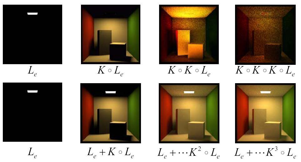
22 Solving the Rendering Equation (=how to compute L?) L EKL IL KL E ( I K) L E L ( I K) 1 E (using Binomial Theorem) 2 3 L ( I K K K...) E 2 3 L E KE K E K E... where term n corresponds to n-th bounces of light
23 Ray Tracing 2 3 L E KE K E K E... Emission directly From light sources Direct Illumination on surfaces Global Illumination (One bounce indirect) [Mirrors, Refraction] (Two bounce indirect) [Caustics, etc ]
24 Ray Tracing 2 3 L E KE KEKE... Emission directly From light sources OpenGL Shading Direct Illumination on surfaces Global Illumination (One bounce indirect) [Mirrors, Refraction] (Two bounce indirect) [Caustics, etc ]
25
 [Radiosity slides heavily based on Dr. Mario Costa Sousa, Dept. of of CS, U.")
26 Radiosity Radiosity, inspired by ideas from heat transfer, is an application of a finite element method to solving the rendering equation for scenes with purely diffuse surfaces (rendering equation) [Radiosity slides heavily based on Dr. Mario Costa Sousa, Dept. of of CS, U. Of Calgary]
27 Radiosity Calculating the overall light propagation within a scene, for short global illumination is a very difficult problem. With a standard ray tracing algorithm, this is a very time consuming task, since a huge number of rays have to be shot.
28 Radiosity For this reason, the radiosity method was invented. The main idea of the method is to store illumination values on the surfaces of the objects, as the light is propagated starting at the light sources.


")
29 Radiosity Equation: (more details on the board )

30 Ray Tracing
31 Radiosity
32 Diffuse Interreflection (radiosity method)
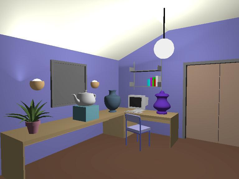
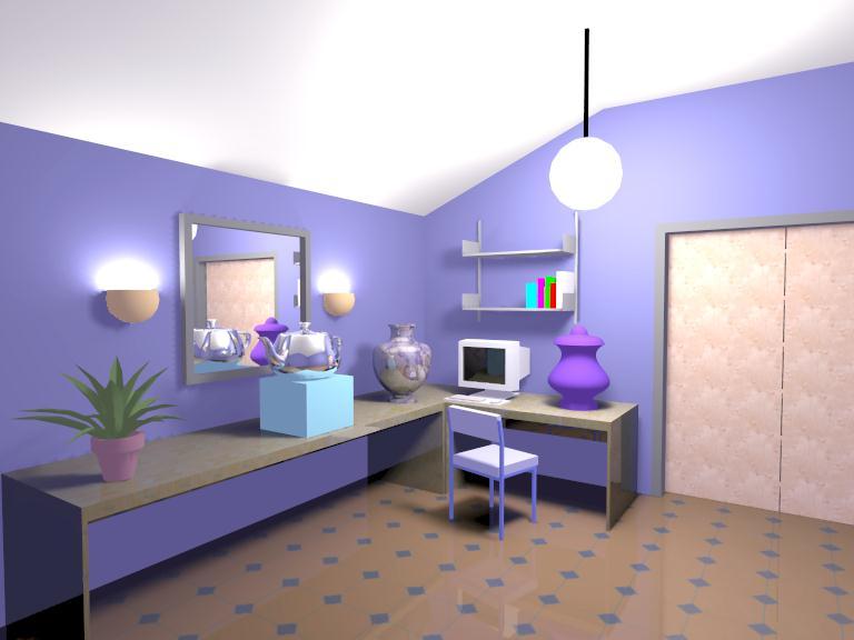
33 Diffuse Interreflection Surface = "diffuse reflector" of light energy, means: any light energy which strikes the surface will be reflected in all directions, dependent only on the angle between the surface's normal and the incoming light vector (Lambert's law).
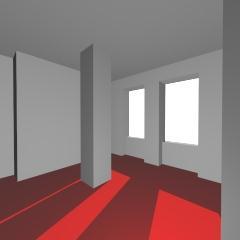
34 Diffuse Interreflection The reflected light energy often is colored, to some small extent, by the color of the surface from which it was reflected. This reflection of light energy in an environment produces a phenomenon known as "color bleeding," where a brightly colored surface's color will "bleed" onto adjacent surfaces.

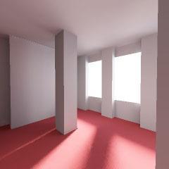
35 Diffuse Interreflection The reflected light energy often is colored, to some small extent, by the color of the surface from which it was reflected. Color bleeding, as both the red and blue walls "bleed" their color onto the white walls, ceiling and floor.
36 Radiosity (Thermal Heat Transfer) The "radiosity" method has its basis in the field of thermal heat transfer. Heat transfer theory describes radiation as the transfer of energy from a surface when that surface has been thermally excited.
37 This encompasses both surfaces which are basic emitters of energy, as with light sources, and surfaces which receive energy from other surfaces and thus have energy to transfer. This "thermal radiation" theory can be used to describe the transfer of many kinds of energy between surfaces, including light energy.
38 Radiosity (Computer Graphics) Assumption #1: surfaces are diffuse emitters and reflectors of energy, emitting and reflecting energy uniformly over their entire area. Assumption #2: an equilibrium solution can be reached; that all of the energy in an environment is accounted for, through absorption and reflection. Also viewpoint independent: the solution will be the same regardless of the viewpoint of the image.
39 The Radiosity Equation The "radiosity equation" describes the amount of energy which can be emitted from a surface, as the sum of the energy inherent in the surface (a light source, for example) and the energy which strikes the surface, being emitted from some other surface. The energy which leaves a surface (surface "j") and strikes another surface (surface "i") is attenuated by two factors: the "form factor" between surfaces "i" and "j", which accounts for the physical relationship between the two surfaces the reflectivity of surface "i, which will absorb a certain percentage of light energy which strikes the surface.
40 The Radiosity Equation B i E i i B j F ij Radiosity of surface i Emissivity of surface i Radiosity of surface j Form Factor of surface j relative to surface i Reflectivity of surface i will absorb a certain percentage of light energy which strikes the surface Surface i Surface j accounts for the physical relationship between the two surfaces
41 The Radiosity Equation B i E i i B j F ij Energy emitted by surface i Surface j Surface i
42 The Radiosity Equation B i E i i B j F ij Energy reaching surface i from other surfaces Surface j Surface i
43 The Radiosity Equation B i E i i B j F ij Energy reflected by surface i Surface j Surface i
44 Radiosity Classic radiosity = finite element method Assumptions Diffuse reflectance Usually polygonal surfaces Advantages Soft shadows and indirect lighting View independent solution Precompute for a set of light sources Useful for walkthroughs
45 Classic Radiosity Algorithm Mesh Surfaces into Elements Compute Form Factors Between Elements Solve Linear System for Radiosities Reconstruct and Display Solution


46 Classic Radiosity Algorithm Mesh Surfaces into Elements Compute Form Factors Between Elements Solve Linear System for Radiosities Reconstruct and Display Solution
47 The Form Factor: The fraction of energy leaving one surface that reaches another surface It is a purely geometric relationship, independent of viewpoint or surface attributes Surface j Surface i
48 Between differential areas, the form factor equals: differential area of surface i, j angle between Normal i and r angle between Normal j and r FdA da i j cos cos i r 2 j Surface j j da j i r vector from da i to da j da i Surface i
49 Between differential areas, the form factor equals: The overall form factor between i and j is found by integrating FdA da j j cos cos i r 2 j F ij 1 A i 2 i A A i j cos cos r j da da i j Surface j j da j i r da i Surface i
50 Next Step: Learn ways of computing form factors Recall the Radiosity Equation: B i E i i B j F ij The F ij are the form factors Form factors independent of radiosities (depend only on scene geometry)
51 Form Factors in (More) Detail F ij 1 i 2 A i A A i j cos cos r j da i da j F ij 1 A i 2 i A A i j cos cos r j V ij da i da j where V ij is the visibility (0 or 1)
52 We have two integrals to compute: F ij 1 A i A i A j cos cos i r 2 j V ij da j da i Area integral over surface i Area integral over surface j Surface j j da j i r da i Surface i
53 The Nusselt Analog Differentiation of the basic form factor equation is difficult even for simple surfaces! Nusselt developed a geometric analog which allows the simple and accurate calculation of the form factor between a surface and a point on a second surface.
54 The Nusselt Analog The "Nusselt analog" involves placing a hemispherical projection body, with unit radius, at a point on a surface. The second surface is spherically projected onto the projection body, then cylindrically projected onto the base of the hemisphere. The form factor is, then, the area projected on the base of the hemisphere divided by the area of the base of the hemisphere.
55 Numerical Integration: The Nusselt Analog This gives the form factor F daiaj A j da i
56 The Nusselt Analog q i r area A j q j 1. Project A j along its normal: A j cos q j 2. Project result on sphere: A j cos q j / r 2 3. Project result on unit circle: A j cos q j cos q i /r 2 4. Divide by unit circle area: A j cos q j cos q i / pr 2 5. Integrate for all points on A j : F da A A j cos cos i r i j 2 j V ij da j sphere projection A j cos q j /r 2 unit circle area p second projection A j cos q j cos q i /r 2
57 Method 1: Hemicube Approximation of Nusselt s analog between a point da i and a polygon A j Polygonal Area (A j ) Infinitesimal Area (da i )
58 Hemicube For convenience, a cube 1 unit high with a top face 2 x 2 is used. Side faces are 2 wide by 1 high. Decide on a resolution for the cube. Say 512 by 512 for the top.
59 The Hemicube In Action
60 The Hemicube In Action
61 The Hemicube In Action This illustration demonstrates the calculation of form factors between a particular surface on the wall of a room and several surfaces of objects in the room.
62 Compute the form factors from a point on a surface to all other surfaces by: Projecting all other surfaces onto the hemicube Storing, at each discrete area, the identifying index of the surface that is closest to the point.
63 Discrete areas with the indices of the surfaces which are ultimately visible to the point. From there the form factors between the point and the surfaces are calculated. For greater accuracy, a large surface would typically be broken into a set of small surfaces before any form factor calculation is performed.
64 Hemicube Method 1. Scan convert all scene objects onto hemicube s 5 faces 2. Use Z buffer to determine visibility term 3. Sum up the delta form factors of the hemicube cells covered by scanned objects 4. Gives form factors from hemicube s base to all elements, i.e. F daiaj for given i and all j
65 Hemicube Algorithms Advantages + First practical method + Use existing rendering systems; Hardware + Computes row of form factors in O(n) Disadvantages - Computes differential-finite form factor - Aliasing errors due to sampling Randomly rotate/shear hemicube - Proximity errors - Visibility errors - Expensive to compute a single form factor
66 Method 2: Area Sampling Subdivide A j into small pieces da j For all da j cast ray daj-daj to determine V ij if visible compute F daidaj cos i cos j FdAdA V i j 2 r sum up F daiaj += F daidaj ij da j da i ray da j A j We have now F daiaj
67 Summary Several ways to find form factors Hemicube was original method + Hardware acceleration + Gives F daiaj for all j in one pass - Aliasing Area sampling methods now preferred Slower than hemicube As accurate as desired since adaptive
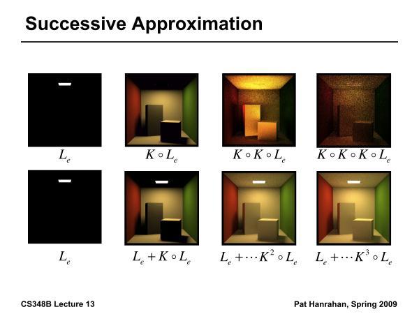
68 Next We have the form factors How do we find the radiosity solution for the scene? The "Full Matrix" Radiosity Algorithm Gathering & Shooting Progressive Radiosity Meshing
69 Radiosity Matrix n j j ij i i i B F E B 1 n n nn n n n n n n n E E E B B B F F F F F F F F F i n j j ij i i E B F B 1 E i B i
70 Radiosity Matrix The "full matrix" radiosity solution calculates the form factors between each pair of surfaces in the environment, then forms a series of simultaneous linear equations. This matrix equation is solved for the "B" values, which can be used as the final intensity (or color) value of each surface. n n nn n n n n n n n E E E B B B F F F F F F F F F
71 Radiosity Matrix This method produces a complete solution, at the substantial cost of first calculating form factors between each pair of surfaces and then the solution of the matrix equation. This leads to substantial costs not only in computation time but in storage.
72 Next We have the form factors How do we find the radiosity solution for the scene? The "Full Matrix" Radiosity Algorithm Gathering & Shooting Progressive Radiosity Meshing
73 Solve [F][B] = [E] Direct methods: O(n 3 ) Gaussian elimination Goral, Torrance, Greenberg, Battaile, 1984 Iterative methods: O(n 2 ) Energy conservation diagonally dominant iteration converges Gauss-Seidel, Jacobi: Gathering Nishita, Nakamae, 1985 Cohen, Greenberg, 1985 Southwell: Shooting Cohen, Chen, Wallace, Greenberg, 1988
74 Gathering In a sense, the light leaving patch i is determined by gathering in the light from the rest of the environment B B i i due E i to B j i n j1 B i j F B j ij F ij B i E i n ifij j1 B j
75 Gathering Gathering light through a hemi-cube allows one patch radiosity to be updated. B i E i n ifij j1 B j
76 Gathering
77 Successive Approximation
78 Shooting Shooting light through a single hemi-cube allows the whole environment's radiosity values to be updated simultaneously. For all j B j B j B i E j ji where F ji F ij A A j i
79 Shooting
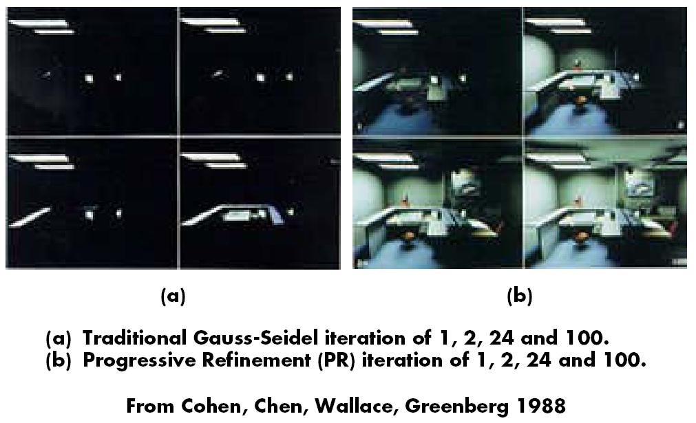
80 Progressive Radiosity
81 Next We have the form factors How do we find the radiosity solution for the scene? The "Full Matrix" Radiosity Algorithm Gathering & Shooting Progressive Radiosity Meshing
82 Accuracy
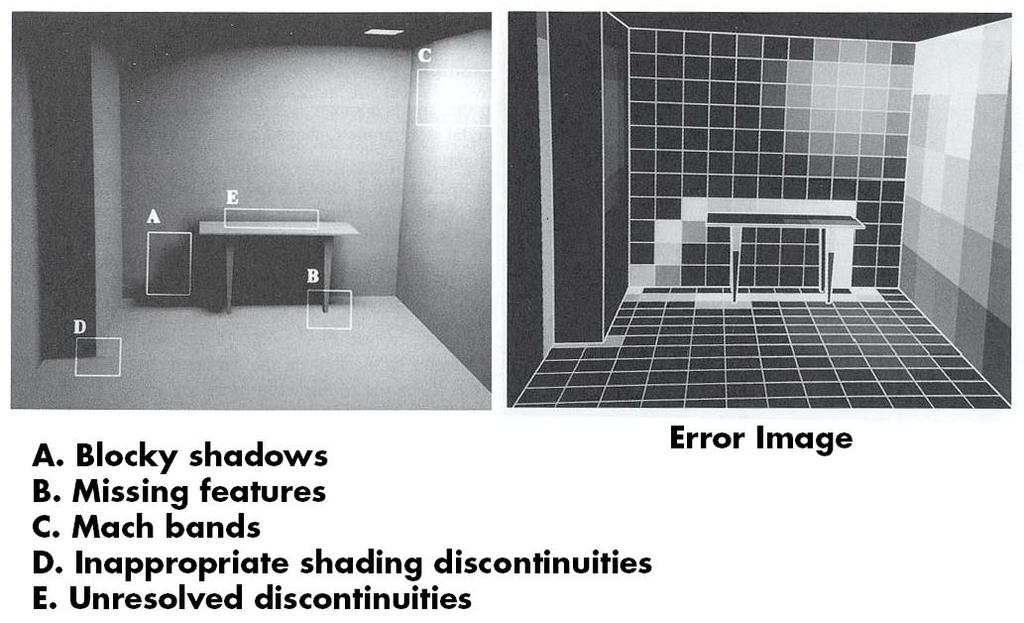
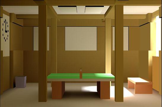
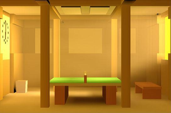
83 Artifacts

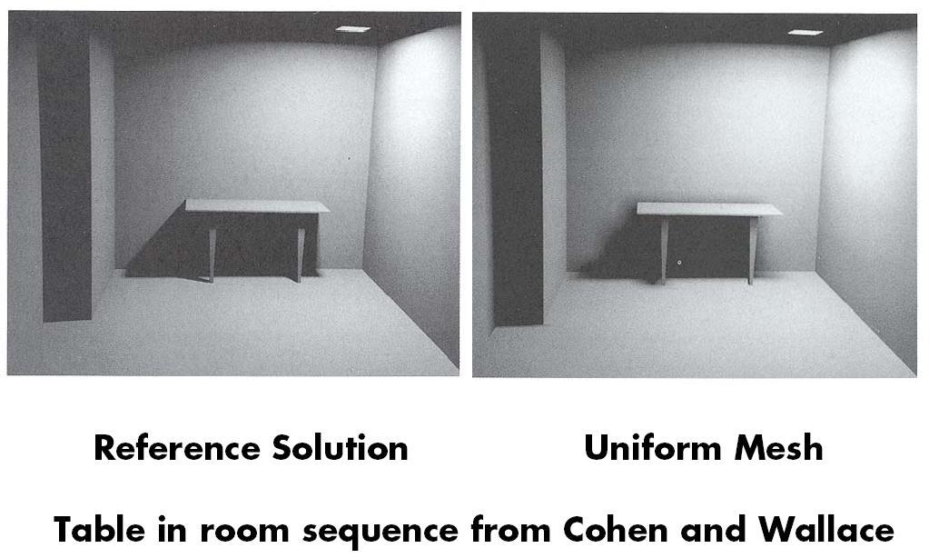
84 Increasing Resolution

85 Adaptive Meshing

86 Some Radiosity Results
, Vol. 18, No. 3, July 1984, pp. 213-222.")
87 The Cornell Box This is the original Cornell box, as simulated by Cindy M. Goral, Kenneth E. Torrance, and Donald P. Greenberg for the 1984 paper Modeling the interaction of Light Between Diffuse Surfaces, Computer Graphics (SIGGRAPH '84 Proceedings), Vol. 18, No. 3, July 1984, pp Because form factors were computed analytically, no occluding objects were included inside the box.

88 The Cornell Box This simulation of the Cornell box was done by Michael F. Cohen and Donald P. Greenberg for the 1985 paper The Hemi-Cube, A Radiosity Solution for Complex Environments, Vol. 19, No. 3, July 1985, pp The hemi-cube allowed form factors to be calculated using scan conversion algorithms (which were available in hardware), and made it possible to calculate shadows from occluding objects.
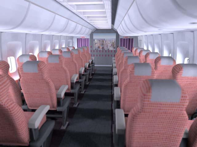
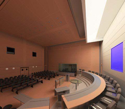
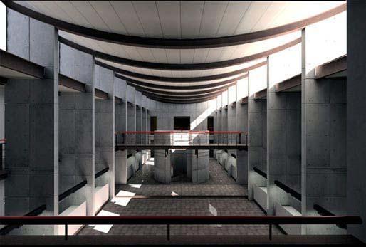
89
90
91
92
93 Discontinuity Meshing Dani Lischinski, Filippo Tampieri and Donald P. Greenberg created this image for the 1992 paper Discontinuity Meshing for Accurate Radiosity. It depicts a scene that represents a pathological case for traditional radiosity images, many small shadow casting details. Notice, in particular, the shadows cast by the windows, and the slats in the chair.
94
95 Opera Lighting This scene from La Boheme demonstrates the use of focused lighting and angular projection of predistorted images for the background. It was rendered by Julie O'B. Dorsey, Francois X. Sillion, and Donald P. Greenberg for the 1991 paper Design and Simulation of Opera Lighting and Projection Effects.
96
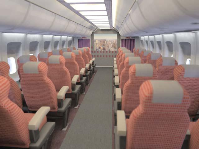
97 Radiosity Factory These two images were rendered by Michael F. Cohen, Shenchang Eric Chen, John R. Wallace and Donald P. Greenberg for the 1988 paper A Progressive Refinement Approach to Fast Radiosity Image Generation. The factory model contains 30,000 patches, and was the most complex radiosity solution computed at that time. The radiosity solution took approximately 5 hours for 2,000 shots, and the image generation required 190 hours; each on a VAX8700.
98
99 Museum Most of the illumination that comes into this simulated museum arrives via the baffles on the ceiling. As the progressive radiosity solution executed, users could witness each of the baffles being illuminated from above, and then reflecting some of this light to the bottom of an adjacent baffle. A portion of this reflected light was eventually bounced down into the room. The image appeared on the proceedings cover of SIGGRAPH 1988.
100
101
102
103
104
105
106
Global Illumination CS334. Daniel G. Aliaga Department of Computer Science Purdue University
 Global Illumination CS334 Daniel G. Aliaga Department of Computer Science Purdue University Recall: Lighting and Shading Light sources Point light Models an omnidirectional light source (e.g., a bulb)
Radiosity. Early Radiosity. Page 1
 Page 1 Radiosity Classic radiosity = finite element method Assumptions Diffuse reflectance Usually polygonal surfaces Advantages Soft shadows and indirect lighting View independent solution Precompute
To Do. Advanced Computer Graphics. Course Outline. Course Outline. Illumination Models. Diffuse Interreflection
 Advanced Computer Graphics CSE 163 [Spring 017], Lecture 11 Ravi Ramamoorthi http://www.cs.ucsd.edu/~ravir To Do Assignment due May 19 Should already be well on way. Contact us for difficulties etc. This
Local vs. Global Illumination & Radiosity
 Last Time? Local vs. Global Illumination & Radiosity Ray Casting & Ray-Object Intersection Recursive Ray Tracing Distributed Ray Tracing An early application of radiative heat transfer in stables. Reading
Global Illumination and the Rendering Equation
 CS294-13: Special Topics Lecture #3 Advanced Computer Graphics University of California, Berkeley Handout Date??? Global Illumination and the Rendering Equation Lecture #3: Wednesday, 9 September 2009
The Rendering Equation & Monte Carlo Ray Tracing
 Last Time? Local Illumination & Monte Carlo Ray Tracing BRDF Ideal Diffuse Reflectance Ideal Specular Reflectance The Phong Model Radiosity Equation/Matrix Calculating the Form Factors Aj Ai Reading for
CS770/870 Spring 2017 Radiosity
 Preview CS770/870 Spring 2017 Radiosity Indirect light models Brief radiosity overview Radiosity details bidirectional reflectance radiosity equation radiosity approximation Implementation details hemicube
CS770/870 Spring 2017 Radiosity
 CS770/870 Spring 2017 Radiosity Greenberg, SIGGRAPH 86 Tutorial Spencer, SIGGRAPH 93 Slide Set, siggraph.org/education/materials/hypergraph/radiosity/radiosity.htm Watt, 3D Computer Graphics -- Third Edition,
Motivation: Monte Carlo Rendering. Sampling and Reconstruction of Visual Appearance. Caustics. Illumination Models. Overview of lecture.
 Sampling and Reconstruction of Visual Appearance CSE 74 [Winter 8], Lecture 3 Ravi Ramamoorthi http://www.cs.ucsd.edu/~ravir Motivation: Monte Carlo Rendering Key application area for sampling/reconstruction
Global Illumination. Global Illumination. Direct Illumination vs. Global Illumination. Indirect Illumination. Soft Shadows.
 CSCI 480 Computer Graphics Lecture 18 Global Illumination BRDFs Raytracing and Radiosity Subsurface Scattering Photon Mapping [Ch. 13.4-13.5] March 28, 2012 Jernej Barbic University of Southern California
A Brief Overview of. Global Illumination. Thomas Larsson, Afshin Ameri Mälardalen University
 A Brief Overview of Global Illumination Thomas Larsson, Afshin Ameri Mälardalen University 1 What is Global illumination? Global illumination is a general name for realistic rendering algorithms Global
Global Illumination. CSCI 420 Computer Graphics Lecture 18. BRDFs Raytracing and Radiosity Subsurface Scattering Photon Mapping [Ch
 CSCI 420 Computer Graphics Lecture 18 Global Illumination Jernej Barbic University of Southern California BRDFs Raytracing and Radiosity Subsurface Scattering Photon Mapping [Ch. 13.4-13.5] 1 Global Illumination
Anti-aliasing. Images and Aliasing
 CS 130 Anti-aliasing Images and Aliasing Aliasing errors caused by rasterizing How to correct them, in general 2 1 Aliased Lines Stair stepping and jaggies 3 Remove the jaggies Anti-aliased Lines 4 2 Aliasing
Radiosity. Johns Hopkins Department of Computer Science Course : Rendering Techniques, Professor: Jonathan Cohen
 Radiosity Radiosity Concept Global computation of diffuse interreflections among scene objects Diffuse lighting changes fairly slowly across a surface Break surfaces up into some number of patches Assume
S U N G - E U I YO O N, K A I S T R E N D E R I N G F R E E LY A VA I L A B L E O N T H E I N T E R N E T
 S U N G - E U I YO O N, K A I S T R E N D E R I N G F R E E LY A VA I L A B L E O N T H E I N T E R N E T Copyright 2018 Sung-eui Yoon, KAIST freely available on the internet http://sglab.kaist.ac.kr/~sungeui/render
Lightscape A Tool for Design, Analysis and Presentation. Architecture Integrated Building Systems
 Lightscape A Tool for Design, Analysis and Presentation Architecture 4.411 Integrated Building Systems Lightscape A Tool for Design, Analysis and Presentation Architecture 4.411 Building Technology Laboratory
Computer Graphics. Lecture 14 Bump-mapping, Global Illumination (1)
") Computer Graphics Lecture 14 Bump-mapping, Global Illumination (1) Today - Bump mapping - Displacement mapping - Global Illumination Radiosity Bump Mapping - A method to increase the realism of 3D objects
Computer Graphics Lecture 14 Bump-mapping, Global Illumination (1) Today - Bump mapping - Displacement mapping - Global Illumination Radiosity Bump Mapping - A method to increase the realism of 3D objects
CS 428: Fall Introduction to. Radiosity. Andrew Nealen, Rutgers, /7/2009 1
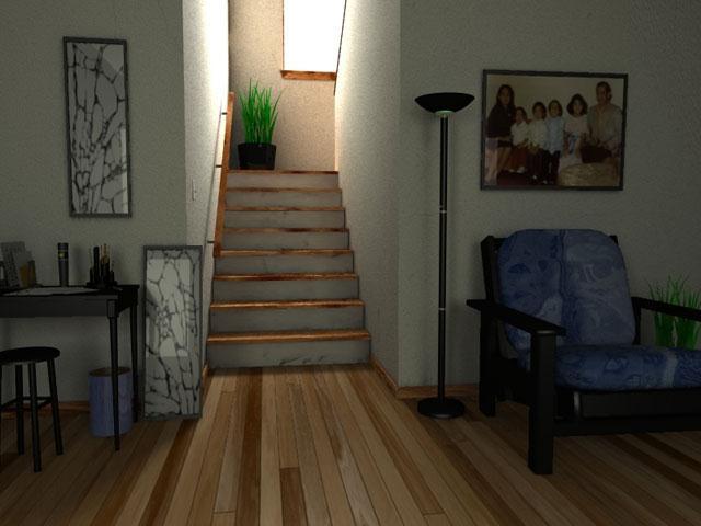
 CS 428: Fall 2009 Introduction to Computer Graphics Radiosity 12/7/2009 1 Problems with diffuse lighting A Daylight Experiment, John Ferren 12/7/2009 2 Problems with diffuse lighting 12/7/2009 3 Direct
Global Illumination. Global Illumination. Direct Illumination vs. Global Illumination. Indirect Illumination. Soft Shadows.
 CSCI 420 Computer Graphics Lecture 18 Global Illumination Jernej Barbic University of Southern California BRDFs Raytracing and Radiosity Subsurface Scattering Photon Mapping [Angel Ch. 11] 1 Global Illumination
Global Illumination. CMPT 361 Introduction to Computer Graphics Torsten Möller. Machiraju/Zhang/Möller
 Global Illumination CMPT 361 Introduction to Computer Graphics Torsten Möller Reading Foley, van Dam (better): Chapter 16.7-13 Angel: Chapter 5.11, 11.1-11.5 2 Limitation of local illumination A concrete
Introduction to Radiosity
 Introduction to Radiosity John F. Hughes, Andries van Dam Applets by Nick Diakopoulos Andries van Dam November 12, 2009 Radiosity 1/48 Radiosity for Inter-Object Diffuse Reflection Color Bleeding Soft
Global Illumination. COMP 575/770 Spring 2013
 Global Illumination COMP 575/770 Spring 2013 Final Exam and Projects COMP 575 Final Exam Friday, May 3 4:00 pm COMP 770 (and 575 extra credit) Projects Final report due by end of day, May 1 Presentations:
Outline of Lecture. Real-Time High Quality Rendering. Geometry or Vertex Pipeline. Basic Hardware Pipeline. Pixel or Fragment Pipeline
 Real-Time High Quality Rendering CSE 274 [Fall 2015], Lecture 2 Graphics Hardware Pipeline, Reflection and Rendering Equations, Taonomy of Methods http://www.cs.ucsd.edu/~ravir Outline of Lecture Taonomy
Global Illumination. Why Global Illumination. Pros/Cons and Applications. What s Global Illumination
 Global Illumination Why Global Illumination Last lecture Basic rendering concepts Primitive-based rendering Today: Global illumination Ray Tracing, and Radiosity (Light-based rendering) What s Global Illumination
6. Illumination, Lighting
 Jorg s Graphics Lecture Notes 6. Illumination, Lighting 1 6. Illumination, Lighting No ray tracing in OpenGL! ray tracing: direct paths COP interreflection: soft shadows, color bleeding. umbra, penumbra,
Topic 9: Lighting & Reflection models 9/10/2016. Spot the differences. Terminology. Two Components of Illumination. Ambient Light Source
 Topic 9: Lighting & Reflection models Lighting & reflection The Phong reflection model diffuse component ambient component specular component Spot the differences Terminology Illumination The transport
Topic 9: Lighting & Reflection models. Lighting & reflection The Phong reflection model diffuse component ambient component specular component
 Topic 9: Lighting & Reflection models Lighting & reflection The Phong reflection model diffuse component ambient component specular component Spot the differences Terminology Illumination The transport
Core ideas: Neumann series
 Radiosity methods Core ideas: Neumann series We have B( x) = E( x) + ρ d ( x) B( u) cosθ i cosθ s all other surfaces πr(x,u) 2 Vis( x,u)da u Can write: Which gives B = E + ρkb B = E + (ρk)e + (ρk)(ρk)e
Lighting. Figure 10.1
 We have learned to build three-dimensional graphical models and to display them. However, if you render one of our models, you might be disappointed to see images that look flat and thus fail to show the
A Survey of Radiosity and Ray-tracing. Methods in Global Illumination
 A Survey of Radiosity and Ray-tracing Methods in Global Illumination Submitted by Ge Jin 12 th Dec 2000 To Dr. James Hahn Final Project of CS368 Advanced Topics in Computer Graphics Contents Abstract...3
CS635 Spring Department of Computer Science Purdue University
 Light Transport CS635 Spring 2010 Daniel G Aliaga Daniel G. Aliaga Department of Computer Science Purdue University Topics Local and GlobalIllumination Models Helmholtz Reciprocity Dual Photography/Light
Advanced Graphics. Global Illumination. Alex Benton, University of Cambridge Supported in part by Google UK, Ltd
 Advanced Graphics Global Illumination 1 Alex Benton, University of Cambridge A.Benton@damtp.cam.ac.uk Supported in part by Google UK, Ltd What s wrong with raytracing? Soft shadows are expensive Shadows
Lecture 33 of 41. Ray Tracing, Part 2 of 2: Distributed RT & Radiosity/RT Hybrid Systems
 Ray Tracing, Part 2 of 2: Distributed RT & Radiosity/RT Hybrid Systems William H. Hsu Department of Computing and Information Sciences, KSU KSOL course pages: http://bit.ly/hgvxlh / http://bit.ly/evizre
MIT Monte-Carlo Ray Tracing. MIT EECS 6.837, Cutler and Durand 1
 MIT 6.837 Monte-Carlo Ray Tracing MIT EECS 6.837, Cutler and Durand 1 Schedule Review Session: Tuesday November 18 th, 7:30 pm bring lots of questions! Quiz 2: Thursday November 20 th, in class (one weeks
Simple Lighting/Illumination Models
 Simple Lighting/Illumination Models Scene rendered using direct lighting only Photograph Scene rendered using a physically-based global illumination model with manual tuning of colors (Frederic Drago and
Schedule. MIT Monte-Carlo Ray Tracing. Radiosity. Review of last week? Limitations of radiosity. Radiosity
 Schedule Review Session: Tuesday November 18 th, 7:30 pm, Room 2-136 bring lots of questions! MIT 6.837 Monte-Carlo Ray Tracing Quiz 2: Thursday November 20 th, in class (one weeks from today) MIT EECS
Computer Graphics. Lecture 13. Global Illumination 1: Ray Tracing and Radiosity. Taku Komura
 Computer Graphics Lecture 13 Global Illumination 1: Ray Tracing and Radiosity Taku Komura 1 Rendering techniques Can be classified as Local Illumination techniques Global Illumination techniques Local
Illumination Algorithms
 Global Illumination Illumination Algorithms Digital Lighting and Rendering CGT 340 The goal of global illumination is to model all possible paths of light to the camera. Global Illumination Global illumination
Rendering Light Reflection Models
 Rendering Light Reflection Models Visual Imaging in the Electronic Age Donald P. Greenberg October 3, 2017 Lecture #13 Program of Computer Graphics, Cornell University General Electric - 167 Cornell in
The Rendering Equation and Path Tracing
 The Rendering Equation and Path Tracing Louis Feng April 22, 2004 April 21, 2004 Realistic Image Synthesis (Spring 2004) 1 Topics The rendering equation Original form Meaning of the terms Integration Path
Photon Maps. The photon map stores the lighting information on points or photons in 3D space ( on /near 2D surfaces)
") Photon Mapping 1/36 Photon Maps The photon map stores the lighting information on points or photons in 3D space ( on /near 2D surfaces) As opposed to the radiosity method that stores information on surface
Photon Mapping 1/36 Photon Maps The photon map stores the lighting information on points or photons in 3D space ( on /near 2D surfaces) As opposed to the radiosity method that stores information on surface
CMSC427 Shading Intro. Credit: slides from Dr. Zwicker
 CMSC427 Shading Intro Credit: slides from Dr. Zwicker 2 Today Shading Introduction Radiometry & BRDFs Local shading models Light sources Shading strategies Shading Compute interaction of light with surfaces
Light Transport CS434. Daniel G. Aliaga Department of Computer Science Purdue University
 Light Transport CS434 Daniel G. Aliaga Department of Computer Science Purdue University Topics Local and Global Illumination Models Helmholtz Reciprocity Dual Photography/Light Transport (in Real-World)
CSE 681 Illumination and Phong Shading
 CSE 681 Illumination and Phong Shading Physics tells us What is Light? We don t see objects, we see light reflected off of objects Light is a particle and a wave The frequency of light What is Color? Our
Computer Graphics. Lecture 10. Global Illumination 1: Ray Tracing and Radiosity. Taku Komura 12/03/15
 Computer Graphics Lecture 10 Global Illumination 1: Ray Tracing and Radiosity Taku Komura 1 Rendering techniques Can be classified as Local Illumination techniques Global Illumination techniques Local
Introduction to Radiosity
 Introduction to Radiosity Produce photorealistic pictures using global illumination Mathematical basis from the theory of heat transfer Enables color bleeding Provides view independent representation Unfortunately,
Computer Graphics Global Illumination
 Computer Graphics 2016 14. Global Illumination Hongxin Zhang State Key Lab of CAD&CG, Zhejiang University 2017-01-09 Course project - Tomorrow - 3 min presentation - 2 min demo Outline - Shadows - Radiosity
GLOBAL ILLUMINATION. Christopher Peters INTRODUCTION TO COMPUTER GRAPHICS AND INTERACTION
 DH2323 DGI17 INTRODUCTION TO COMPUTER GRAPHICS AND INTERACTION GLOBAL ILLUMINATION Christopher Peters CST, KTH Royal Institute of Technology, Sweden chpeters@kth.se http://kth.academia.edu/christopheredwardpeters
CS-184: Computer Graphics. Today. Lecture #16: Global Illumination. Sunday, November 8, 2009
 C-184: Computer Graphics Lecture #16: Global Illumination Prof. James O Brien University of California, Berkeley V2009-F-16-1.0 Today The Rendering Equation Radiosity Method Photon Mapping Ambient Occlusion
Illumination. The slides combine material from Andy van Dam, Spike Hughes, Travis Webb and Lyn Fong
 INTRODUCTION TO COMPUTER GRAPHIC S Illumination The slides combine material from Andy van Dam, Spike Hughes, Travis Webb and Lyn Fong Andries van Dam October 29, 2009 Illumination Models 1/30 Outline Physical
Interactive Rendering of Globally Illuminated Glossy Scenes
 Interactive Rendering of Globally Illuminated Glossy Scenes Wolfgang Stürzlinger, Rui Bastos Dept. of Computer Science, University of North Carolina at Chapel Hill {stuerzl bastos}@cs.unc.edu Abstract.
Today. Anti-aliasing Surface Parametrization Soft Shadows Global Illumination. Exercise 2. Path Tracing Radiosity
 Today Anti-aliasing Surface Parametrization Soft Shadows Global Illumination Path Tracing Radiosity Exercise 2 Sampling Ray Casting is a form of discrete sampling. Rendered Image: Sampling of the ground
Final Project: Real-Time Global Illumination with Radiance Regression Functions
 Volume xx (200y), Number z, pp. 1 5 Final Project: Real-Time Global Illumination with Radiance Regression Functions Fu-Jun Luan Abstract This is a report for machine learning final project, which combines
Overview. Radiometry and Photometry. Foundations of Computer Graphics (Spring 2012)
") Foundations of Computer Graphics (Spring 2012) CS 184, Lecture 21: Radiometry http://inst.eecs.berkeley.edu/~cs184 Overview Lighting and shading key in computer graphics HW 2 etc. ad-hoc shading models,
Foundations of Computer Graphics (Spring 2012) CS 184, Lecture 21: Radiometry http://inst.eecs.berkeley.edu/~cs184 Overview Lighting and shading key in computer graphics HW 2 etc. ad-hoc shading models,
Computer Graphics Global Illumination
 ! Computer Graphics 2013! 14. Global Illumination Hongxin Zhang State Key Lab of CAD&CG, Zhejiang University 2013-10-30 Final examination - Friday night, 7:30PM ~ 9:00PM, Nov. 8th - Room 103 (?), CaoGuangBiao
Global Illumination The Game of Light Transport. Jian Huang
 Global Illumination The Game of Light Transport Jian Huang Looking Back Ray-tracing and radiosity both computes global illumination Is there a more general methodology? It s a game of light transport.
Rendering Light Reflection Models
 Rendering Light Reflection Models Visual Imaging in the Electronic Age Donald P. Greenberg October 27, 2015 Lecture #18 Goal of Realistic Imaging The resulting images should be physically accurate and
Korrigeringar: An introduction to Global Illumination. Global Illumination. Examples of light transport notation light
 An introduction to Global Illumination Tomas Akenine-Möller Department of Computer Engineering Chalmers University of Technology Korrigeringar: Intel P4 (200): ~42M transistorer Intel P4 EE (2004): 78M
Precomputed Radiance Transfer: Theory and Practice
 1 Precomputed Radiance Transfer: Peter-Pike Sloan Microsoft Jaakko Lehtinen Helsinki Univ. of Techn. & Remedy Entertainment Jan Kautz MIT 2 Introduction Jan Kautz MIT 3 Introduction We see here an example
THE goal of rendering algorithms is to synthesize images of virtual scenes. Global illumination
 2 Fundamentals of Light Transport He who loves practice without theory is like the sailor who boards ship without a rudder and compass and never knows where he may cast. Leonardo Da Vinci, 1452 1519 THE
Lighting. To do. Course Outline. This Lecture. Continue to work on ray programming assignment Start thinking about final project
 To do Continue to work on ray programming assignment Start thinking about final project Lighting Course Outline 3D Graphics Pipeline Modeling (Creating 3D Geometry) Mesh; modeling; sampling; Interaction
CS354R: Computer Game Technology
 CS354R: Computer Game Technology Real-Time Global Illumination Fall 2018 Global Illumination Mirror s Edge (2008) 2 What is Global Illumination? Scene recreates feel of physically-based lighting models
Photon Mapping. Due: 3/24/05, 11:59 PM
 CS224: Interactive Computer Graphics Photon Mapping Due: 3/24/05, 11:59 PM 1 Math Homework 20 Ray Tracing 20 Photon Emission 10 Russian Roulette 10 Caustics 15 Diffuse interreflection 15 Soft Shadows 10
Illumination. Michael Kazhdan ( /657) HB Ch. 14.1, 14.2 FvDFH 16.1, 16.2
 HB Ch. 14.1, 14.2 FvDFH 16.1, 16.2") Illumination Michael Kazhdan (601.457/657) HB Ch. 14.1, 14.2 FvDFH 16.1, 16.2 Ray Casting Image RayCast(Camera camera, Scene scene, int width, int height) { Image image = new Image(width, height); for
Illumination Michael Kazhdan (601.457/657) HB Ch. 14.1, 14.2 FvDFH 16.1, 16.2 Ray Casting Image RayCast(Camera camera, Scene scene, int width, int height) { Image image = new Image(width, height); for
Hemi-Cube Ray-Tracing: A Method for Generating Soft Shadows
 EUROGRAPHICS 90 / C.E. Vandoni and D.A Duce (Editors) Elsevier Science Publishers B.V. (North-Holland) Eurographics Association, 1990 365 Hemi-Cube Ray-Tracing: A Method for Generating Soft Shadows Urs
Introduction. Chapter Computer Graphics
 Chapter 1 Introduction 1.1. Computer Graphics Computer graphics has grown at an astounding rate over the last three decades. In the 1970s, frame-buffers capable of displaying digital images were rare and
Rendering. Mike Bailey. Rendering.pptx. The Rendering Equation
 1 Rendering This work is licensed under a Creative Commons Attribution-NonCommercial-NoDerivatives 4.0 International License Mike Bailey mjb@cs.oregonstate.edu Rendering.pptx d i d 0 P P d i The Rendering
The Rendering Equation. Computer Graphics CMU /15-662
 The Rendering Equation Computer Graphics CMU 15-462/15-662 Review: What is radiance? Radiance at point p in direction N is radiant energy ( #hits ) per unit time, per solid angle, per unit area perpendicular
Path Tracing part 2. Steve Rotenberg CSE168: Rendering Algorithms UCSD, Spring 2017
 Path Tracing part 2 Steve Rotenberg CSE168: Rendering Algorithms UCSD, Spring 2017 Monte Carlo Integration Monte Carlo Integration The rendering (& radiance) equation is an infinitely recursive integral
11/2/2010. In the last lecture. Monte-Carlo Ray Tracing : Path Tracing. Today. Shadow ray towards the light at each vertex. Path Tracing : algorithm
 Comuter Grahics Global Illumination: Monte-Carlo Ray Tracing and Photon Maing Lecture 11 In the last lecture We did ray tracing and radiosity Ray tracing is good to render secular objects but cannot handle
Raytracing & Epsilon. Today. Last Time? Forward Ray Tracing. Does Ray Tracing Simulate Physics? Local Illumination
 Raytracing & Epsilon intersects light @ t = 25.2 intersects sphere1 @ t = -0.01 & Monte Carlo Ray Tracing intersects sphere1 @ t = 10.6 Solution: advance the ray start position epsilon distance along the
Recollection. Models Pixels. Model transformation Viewport transformation Clipping Rasterization Texturing + Lights & shadows
 Recollection Models Pixels Model transformation Viewport transformation Clipping Rasterization Texturing + Lights & shadows Can be computed in different stages 1 So far we came to Geometry model 3 Surface
Radiance. Radiance properties. Radiance properties. Computer Graphics (Fall 2008)
") Computer Graphics (Fall 2008) COMS 4160, Lecture 19: Illumination and Shading 2 http://www.cs.columbia.edu/~cs4160 Radiance Power per unit projected area perpendicular to the ray per unit solid angle in
Computer Graphics (Fall 2008) COMS 4160, Lecture 19: Illumination and Shading 2 http://www.cs.columbia.edu/~cs4160 Radiance Power per unit projected area perpendicular to the ray per unit solid angle in
Sung-Eui Yoon ( 윤성의 )
") CS380: Computer Graphics Illumination and Shading Sung-Eui Yoon ( 윤성의 ) Course URL: http://sglab.kaist.ac.kr/~sungeui/cg/ Course Objectives (Ch. 10) Know how to consider lights during rendering models
CS380: Computer Graphics Illumination and Shading Sung-Eui Yoon ( 윤성의 ) Course URL: http://sglab.kaist.ac.kr/~sungeui/cg/ Course Objectives (Ch. 10) Know how to consider lights during rendering models
Shading. Brian Curless CSE 557 Autumn 2017
 Shading Brian Curless CSE 557 Autumn 2017 1 Reading Optional: Angel and Shreiner: chapter 5. Marschner and Shirley: chapter 10, chapter 17. Further reading: OpenGL red book, chapter 5. 2 Basic 3D graphics
in order to apply the depth buffer operations.
 into spans (we called span the intersection segment between a projected patch and a proxel array line). These spans are generated simultaneously for all the patches on the full processor array, as the
Advanced Graphics. Path Tracing and Photon Mapping Part 2. Path Tracing and Photon Mapping
 Advanced Graphics Path Tracing and Photon Mapping Part 2 Path Tracing and Photon Mapping Importance Sampling Combine importance sampling techniques Reflectance function (diffuse + specular) Light source
2/1/10. Outline. The Radiance Equation. Light: Flux Equilibrium. Light: Radiant Power. Light: Equation. Radiance. Jan Kautz
 Outline Jan Kautz Basic terms in radiometry Radiance Reflectance The operator form of the radiance equation Meaning of the operator form Approximations to the radiance equation 2005 Mel Slater, 2006 Céline
Part I The Basic Algorithm. Principles of Photon Mapping. A two-pass global illumination method Pass I Computing the photon map
 Part I The Basic Algorithm 1 Principles of A two-pass global illumination method Pass I Computing the photon map A rough representation of the lighting in the scene Pass II rendering Regular (distributed)
Virtual Spherical Lights for Many-Light Rendering of Glossy Scenes
 Virtual Spherical Lights for Many-Light Rendering of Glossy Scenes Miloš Hašan Jaroslav Křivánek * Bruce Walter Kavita Bala Cornell University * Charles University in Prague Global Illumination Effects
Monte Carlo Ray-tracing and Rendering
 ITN, Norrko ping February 3, 2012 Monte Carlo Ray-tracing and Rendering P ROJECT IN A DVANCED G LOBAL I LLUMINATION AND R ENDERING TNCG15 Authors: Henrik Ba cklund Niklas Neijman Contact: henba892@student.liu.se
Computer Graphics (CS 4731) Lecture 16: Lighting, Shading and Materials (Part 1)
 Lecture 16: Lighting, Shading and Materials (Part 1)") Computer Graphics (CS 4731) Lecture 16: Lighting, Shading and Materials (Part 1) Prof Emmanuel Agu Computer Science Dept. Worcester Polytechnic Institute (WPI) Why do we need Lighting & shading? Sphere
Computer Graphics (CS 4731) Lecture 16: Lighting, Shading and Materials (Part 1) Prof Emmanuel Agu Computer Science Dept. Worcester Polytechnic Institute (WPI) Why do we need Lighting & shading? Sphere
Light Reflection Models
 Light Reflection Models Visual Imaging in the Electronic Age Donald P. Greenberg October 21, 2014 Lecture #15 Goal of Realistic Imaging From Strobel, Photographic Materials and Processes Focal Press, 186.
Lighting and Shading Computer Graphics I Lecture 7. Light Sources Phong Illumination Model Normal Vectors [Angel, Ch
 15-462 Computer Graphics I Lecture 7 Lighting and Shading February 12, 2002 Frank Pfenning Carnegie Mellon University http://www.cs.cmu.edu/~fp/courses/graphics/ Light Sources Phong Illumination Model
Parallel Visibility Computations for Parallel Radiosity W. Sturzlinger and C. Wild Institute for Computer Science, Johannes Kepler University of Linz,
 Parallel Visibility Computations for Parallel Radiosity by W. Sturzlinger and C. Wild Johannes Kepler University of Linz Institute for Computer Science Department for Graphics and parallel Processing Altenbergerstrae
Computer Graphics (CS 543) Lecture 7b: Intro to lighting, Shading and Materials + Phong Lighting Model
 Lecture 7b: Intro to lighting, Shading and Materials + Phong Lighting Model") Computer Graphics (CS 543) Lecture 7b: Intro to lighting, Shading and Materials + Phong Lighting Model Prof Emmanuel Agu Computer Science Dept. Worcester Polytechnic Institute (WPI) Why do we need Lighting
Computer Graphics (CS 543) Lecture 7b: Intro to lighting, Shading and Materials + Phong Lighting Model Prof Emmanuel Agu Computer Science Dept. Worcester Polytechnic Institute (WPI) Why do we need Lighting
Lighting and Shading. Slides: Tamar Shinar, Victor Zordon
 Lighting and Shading Slides: Tamar Shinar, Victor Zordon Why we need shading Suppose we build a model of a sphere using many polygons and color each the same color. We get something like But we want 2
Virtual Reality for Human Computer Interaction
 Virtual Reality for Human Computer Interaction Appearance: Lighting Representation of Light and Color Do we need to represent all I! to represent a color C(I)? No we can approximate using a three-color
Photon Mapping. Michael Doggett Department of Computer Science Lund university
 Photon Mapping Michael Doggett Department of Computer Science Lund university Outline Photon Mapping (ch. 14 in textbook) Progressive Stochastic 2011 Michael Doggett How to make light sampling faster?
The Design and Implementation of a Radiosity Renderer. Alexandru Telea
 The Design and Implementation of a Radiosity Renderer Alexandru Telea 2 Contents 1 Overview of this Thesis 5 2 The Radiosity Theory 7 2.1 Radiometry.............................. 7 2.1.1 Radiant energy
Today. Participating media. Participating media. Rendering Algorithms: Participating Media and. Subsurface scattering
 Today Rendering Algorithms: Participating Media and Subsurface Scattering Introduction Rendering participating media Rendering subsurface scattering Spring 2009 Matthias Zwicker Participating media Participating
CSE 167: Introduction to Computer Graphics Lecture #6: Lights. Jürgen P. Schulze, Ph.D. University of California, San Diego Fall Quarter 2016
 CSE 167: Introduction to Computer Graphics Lecture #6: Lights Jürgen P. Schulze, Ph.D. University of California, San Diego Fall Quarter 2016 Announcements Thursday in class: midterm #1 Closed book Material
Raytracing CS148 AS3. Due :59pm PDT
 Raytracing CS148 AS3 Due 2010-07-25 11:59pm PDT We start our exploration of Rendering - the process of converting a high-level object-based description of scene into an image. We will do this by building
Today s class. Simple shadows Shading Lighting in OpenGL. Informationsteknologi. Wednesday, November 21, 2007 Computer Graphics - Class 10 1
 Today s class Simple shadows Shading Lighting in OpenGL Wednesday, November 21, 27 Computer Graphics - Class 1 1 Simple shadows Simple shadows can be gotten by using projection matrices Consider a light
Shading, lighting, & BRDF Theory. Cliff Lindsay, PHD
 Shading, lighting, & BRDF Theory Cliff Lindsay, PHD Overview of today s lecture BRDF Characteristics Lights in terms of BRDFs Classes of BRDFs Ambient light & Shadows in terms of BRDFs Decomposing Reflection
Visualisatie BMT. Rendering. Arjan Kok
 Visualisatie BMT Rendering Arjan Kok a.j.f.kok@tue.nl 1 Lecture overview Color Rendering Illumination 2 Visualization pipeline Raw Data Data Enrichment/Enhancement Derived Data Visualization Mapping Abstract
Rendering Algorithms: Real-time indirect illumination. Spring 2010 Matthias Zwicker
 Rendering Algorithms: Real-time indirect illumination Spring 2010 Matthias Zwicker Today Real-time indirect illumination Ray tracing vs. Rasterization Screen space techniques Visibility & shadows Instant
Today. Global illumination. Shading. Interactive applications. Rendering pipeline. Computergrafik. Shading Introduction Local shading models
 Computergrafik Matthias Zwicker Universität Bern Herbst 2009 Today Introduction Local shading models Light sources strategies Compute interaction of light with surfaces Requires simulation of physics Global
rendering equation computer graphics rendering equation 2009 fabio pellacini 1
 rendering equation computer graphics rendering equation 2009 fabio pellacini 1 physically-based rendering synthesis algorithms that compute images by simulation the physical behavior of light computer
CS 325 Computer Graphics
 CS 325 Computer Graphics 04 / 02 / 2012 Instructor: Michael Eckmann Today s Topics Questions? Comments? Illumination modelling Ambient, Diffuse, Specular Reflection Surface Rendering / Shading models Flat