CS 325 Computer Graphics
|
|
|
- Preston Walker
- 5 years ago
- Views:
Transcription
1 CS 325 Computer Graphics 04 / 02 / 2012 Instructor: Michael Eckmann
2 Today s Topics Questions? Comments? Illumination modelling Ambient, Diffuse, Specular Reflection Surface Rendering / Shading models Flat Gouraud Phong Ray tracing Ray Sphere intersections Ray Polygon intersections Michael Eckmann - Skidmore College - CS Spring 2012

3 Illumination Illustration of the Phong Reflection Model. Created by Brad Smith, August 7, Licensed under the Creative Commons Attribution-Share Alike 3.0 Unported license. Michael Eckmann - Skidmore College - CS Spring 2012
4 Illumination I = I a k a + f radatten (d L ) I p (k d L N + W(theta)cos ns (phi)) Notice the following: the Phong term is dependent on the point light source and the attenuation factor our whole illumination model at this point is influenced by ambient light and a point light source. Further, our object has diffuse reflection properties and specular reflection properties. And the phi angle is dependent on where the viewer is.
5 Illumination If we have more than one point light source (that are white light), then we sum up over all the light sources i: I = I a k a + Sum all i [f radatten (d L ) I pi (k d L N + W(theta)cos ns (phi))]
6 Illumination If the light sources are not white light sources, then we can separate out the red, green and blue components. Also, if objects are to be colored, then they reflect different wavelengths and absorb others. Specify ambient light now as 3 components: I ar I ag I ab Specify point light now as 3 components: I pr I pg I pb Specify objects with color: O R O G O B I R = I a R k a O R + Sum all i [f radatten (d L ) I pri (k d O R L N + W(theta)cos ns (phi))] I G and I B can be expressed similarly.
7 Illumination We typically want our Intensities to be in the range 0 to 1. With many light sources that are specified as too intense, computed intensities of objects can easily be too large (> 1). We can normalize the range of calculated intensities into the range 0 to 1. Or we can specify our light source intensities better and if any calculations go over 1, then clip them to intensity 1.
8 Directional light source The light sources that we have discussed so far were point light sources which radiated light in all directions. Real lights in the world do not have this property. Instead, real lights typically are directional. A directional light source can be described as having a position a directional vector an angular limit from that vector a color The vector will be the axis in a cone shaped volume. This volume is the only part of space that will be illuminated by this light. Anything outside the cone will not be illuminated by this light. See diagram next slide.
9
10
11 Directional light source To determine how intense the light is from a directional light source on an object we determine the angle between the vector V o from the position of the light to the point on the object we're illuminating and the cone axis vector V l So, we take the dot product: V o V l = cos alpha, alpha is the angle between them. If V o is in the same direction as V l, then the light should be the most intense (alpha = 0). The light should get less intense as we go in larger angles away from V l. We can attenuate the light as function of alpha like so: cos al alpha where al is the attenuation exponent (a property of the light source) --- if al is 0, it's a point light source, the smaller al is, the larger the attenuation is (because the cos is less than 1.)
12 Transparent/Translucent surfaces Transparent, opaque, translucent Transparent refers to the quality of a surface that we can see through. Opaque surfaces, we cannot see through. some transparent objects are translucent --- light is transmitted diffusely in all directions through the material translucent materials make the object viewed through them blurry
13 Transparent/Translucent surfaces Terminology index of refraction of a material is defined to be the ratio of the speed of light in a vacuum to the speed of light in the material. Snell's Law is a relationship between angle of incidence and refraction and indices of refraction.
14
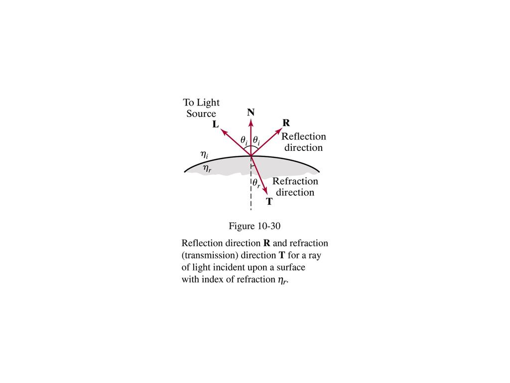
15 Transparent/Translucent surfaces To determine the direction of the refracted ray, the angle ( theta r ) off of -N, we need to know several things the direction of the incoming ray, the angle ( theta i ) of incidence the index of refraction (eta i ) of the material the ray is coming from the index of refraction (eta r ) of the material the ray is entering
16 Transparent/Translucent surfaces Snell's law states that sin ( theta r ) eta i = sin ( theta i ) eta r which can be written as: sin ( theta r ) = ((eta i ) / (eta r )) * sin ( theta i )
17 Transparent/Translucent surfaces Assuming all of our vectors are unit vectors, using Snell's law, according to our textbook we can compute the unit refracted ray, T, to be T = (((eta i ) / (eta r )) cos ( theta r ) cos ( theta r )) N ((eta i ) / (eta r ))L See page 524 in our text. This assumes L is in the direction shown in the diagram 3 slides ago. Verifying that the equation above is correct is left as an exercise to the reader. It may appear on a hw assignment.
18 Transparent/Translucent surfaces Table 17-1 on page 524 in our text shows average indices of refraction for common materials, such as Vacuum (1.0), Ordinary Crown Glass (1.52), Heavy Crown Glass (1.61), Ordinary Flint Glass (1.61), Heavy Flint Glass (1.92), Rock Salt (1.55), Quartz (1.54), Water (1.33), Ice (1.31) Different frequencies of light travel at different speeds through the same material. Therefore, each frequency has its own index of refraction. The indices of refraction above are averages.
19 Illumination Illumination models are used to calculate the color of a point on the surface of an object. A surface rendering (aka shading) method uses the calculations from the illumination model to determine the pixel colors of all the projected points in a scene. Can be done by doing illumination model calculations at each pixel position (like you'll see is done in ray tracing). OR Can be done by doing a small number of illumination calculations and interpolating between pixels (like is often done in scan line algorithms.) Michael Eckmann - Skidmore College - CS Spring 2010
20 Surface Rendering Now that we have an illumination model built, we can use it in different ways to do surface rendering aka shading.
21 Shading Models Constant shading (aka flat shading, aka faceted shading) is the simplest shading model. It is accurate when a polygon face of an object is not approximating a curved surface, all light sources are far and the viewer is far away from the object. Far meaning sufficiently far enough away that N L and R V are constant across the polygon. If we use constant shading but the light and viewer are not sufficiently far enough away then we need to choose a value for each of the dot products and apply it to the whole surface. This calculation is usually done on the centroid of the polygon. Advantages: fast & simple Disadvantages: inaccurate shading if the assumptions are not met.
22 Interpolated shading model Shading Models Assume we're shading a polygon. The shading is interpolated linearly. That is, we calculate a value at two points and interpolate between them to get the value at the points in between --- this saves lots of computation (over computing at each position) and results in a visual improvement over flat shading. This technique was created for triangles e.g. compute the color at the three vertices and interpolate to get the edge colors and then interpolate across the triangle's surface from edge to edge to get the interior colors. Gouraud shading is an interpolation technique that is generalized to arbitrary polygons. Phong shading is another interpolation technique but doesn't interpolate intensities.
23 Shading Models Gouraud shading (aka Gouraud Surface Rendering) is a form of interpolated shading. How to calculate the intensity at the vertices? we have normal vectors to all polygons so, consider all the polygons that meet at that vertex. Drawing on the board. Suppose for example, n polygons all meet at one vertex. We want to approximate the normal of the actual surface at the vertex. We have the normals to all n polygons that meet there. So, to approximate the normal to the vertex we take the average of all n polygon normals. What good is knowing the normal at the vertex? Why do we want to know that?
24 Gouraud shading. Shading Models What good is knowing the normal at the vertex? Why do we want to know that? so we can calculate the intensity at that vertex from the illumination equations. Calculate the intensity at each vertex using the normal we estimate there. Then linearly interpolate the intensity along the edges between the vertices. Then linearly interpolate the intensity along a scan line for the intensities of interior points of the polygon. Example on the board.
25 Shading Models Advantages: easy to implement if already doing a scan line algorithm. Disadvantages: Unrealistic if the polygon doesn't accurately represent the object. This is typical with polygon meshes representing curved surfaces. Mach banding problem when there are discontinuities in intensities at polygon edges, we can sometimes get this unfortunate effect. let's see an example. The shading of the polygon depends on its orientation. If it rotates, we will see an unwanted effect due to the interpolation along a scanline. Example on board. Specular reflection is also averaged over polygons and therefore doesn't accurately show these reflections.
26 Shading Models Phong shading (aka Phong Surface Rendering). Assume we are using a polygon mesh to estimate a surface. Compute the normals at the vertices like we did for Gouraud. Then instead of computing the intensity (color) at the vertices and interpolating the intensities, we interpolate the normals. So, given normals at two points of a polygon, we interpolate over the surface to estimate the normals between the two points. Example picture on the board. Then we have to apply the illumination equation at all the points in between to compute intensity. We didn't have to do this for Gouraud. Problems arise since the interpolation is done in the 3d world space and the pixel intensities are in the image space. More accurate intensity value calculations, more realistic surface highlights and reduced Mach banding.
27 Recap Flat Shading Shading Models Gouraud Shading --- interpolates intensities Phong Shading --- interpolates normal vectors (before calculating illumination.) For these three methods, as speed/efficiency decreases, realism increases (as you'd expect.) They all have the problem of silhouetting. Edges of polygons on the visual edge of an object are apparent. Let's see examples of Gouraud and Phong shading.
28 Game plan Since your fourth programming assignment is to implement a raytracer I will cover ray tracing next Other topics for the remainder of the semester will be ray tracing texture mapping & bump mapping radiosity 3d model representations parametric curves mathematical representation of surfaces as opposed to polygon mesh approximations.
29 Ray Casting Recall Ray Casting which we discussed recently in our topic of Visible Surface Determination. To determine which surface is visible at a pixel, draw a ray starting at the CoP/PRP/eye through the center of the pixel and determine which surface it hits first. This method could be used to determine the color of the pixel with any of the illumination models discussed.
30 Ray Tracing Ray Tracing is a generalization of Ray Casting. Ray tracing is an image generation method that determines the color of a pixel in the image by tracing a ray from the eye (CoP/PRP) through the center of the pixel and out into the world determining if the ray intersect any surfaces if it does, consider only the closest surface. then bounce the ray off this surface one ray each in the direction of the light sources one reflected ray (if surface is specularly reflective) one refracted ray (if surface is transparent/translucent)
31 then bounce the ray off this surface Ray Tracing one ray each in the direction of the light sources one reflected ray (if surface is specularly reflective) one refracted ray (if surface is transparent/translucent) The rays that are in the direction of each of the light sources are called Shadow Rays. If a shadow ray directly hits a light source without first hitting another object then that light influences the color of the surface at that point. The reflected ray is bounced off the object at the angle it makes with the normal vector at the intersection, but on the other side of it (like we saw in the illumination model discussion of specular reflection.) The refracted ray is transmitted through the surface according to Snell's law which we recently covered.
32 Ray Tracing Further, the reflected ray and the refracted ray may also recursively generate shadow, reflected and refracted rays. terminate a path (the bounces) when a ray doesn't intersect a reflective/refractive surface or when we hit the maximum levels of recursion that we specify This ray tracing is done for each pixel in the image!
33 Ray Tracing The image on the next slide shows the original ray from the eye through a pixel and out into the world. It intersects with an object (the pyramid) and only the reflected rays are shown. A more accurate picture to depict ray tracing would show the shadow rays, and the refracted rays (if any).
34
35 Ray Tracing The original ray and it's reflected and refracted rays, and those reflected and refracted rays' reflected and refracted rays and so on can form a tree. Example of this tree on the next slide. Each node in the tree also has shadow rays (but they are not edges in the tree, since they cannot spawn further rays and they are treated differently.) The shadow rays are used to calculate the color/shading of the point on the surface (both the diffuse and specular components.) If a shadow ray does not reach a light source (that is, an object is in the way) then the point we're determining the color of is in the shadow of that light.
36
37 Ray Tracing From the description thusfar of ray tracing, it should be obvious that it often needs to determine if a ray intersects with anything and if so, where does it intersect Ray Tracing is time consuming / computationally expensive. We would like to have efficient methods to determine if a ray intersects with anything compute intersection points Since spheres are among the simplest shapes to ray trace, we'll discuss how to determine intersections between a ray and a sphere first. Then cover ray-polygon intersection calculations.
38 Ray Tracing After we discuss intersection calculations, we'll cover (again) how to compute the reflection ray and the refraction ray, given an incident ray. I'll provide a handout with psuedocode for a ray tracing algorithm.
Reflection and Shading
 Reflection and Shading R. J. Renka Department of Computer Science & Engineering University of North Texas 10/19/2015 Light Sources Realistic rendering requires that we model the interaction between light
Lighting and Shading
 Lighting and Shading Today: Local Illumination Solving the rendering equation is too expensive First do local illumination Then hack in reflections and shadows Local Shading: Notation light intensity in,
9. Illumination and Shading
 9. Illumination and Shading Approaches for visual realism: - Remove hidden surfaces - Shade visible surfaces and reproduce shadows - Reproduce surface properties Texture Degree of transparency Roughness,
CPSC 314 LIGHTING AND SHADING
 CPSC 314 LIGHTING AND SHADING UGRAD.CS.UBC.CA/~CS314 slide credits: Mikhail Bessmeltsev et al 1 THE RENDERING PIPELINE Vertices and attributes Vertex Shader Modelview transform Per-vertex attributes Vertex
CEng 477 Introduction to Computer Graphics Fall
 Illumination Models and Surface-Rendering Methods CEng 477 Introduction to Computer Graphics Fall 2007 2008 Illumination Models and Surface Rendering Methods In order to achieve realism in computer generated
surface: reflectance transparency, opacity, translucency orientation illumination: location intensity wavelength point-source, diffuse source
 walters@buffalo.edu CSE 480/580 Lecture 18 Slide 1 Illumination and Shading Light reflected from nonluminous objects depends on: surface: reflectance transparency, opacity, translucency orientation illumination:
CS5620 Intro to Computer Graphics
 So Far wireframe hidden surfaces Next step 1 2 Light! Need to understand: How lighting works Types of lights Types of surfaces How shading works Shading algorithms What s Missing? Lighting vs. Shading
Photorealism: Ray Tracing
 Photorealism: Ray Tracing Reading Assignment: Chapter 13 Local vs. Global Illumination Local Illumination depends on local object and light sources only Global Illumination at a point can depend on any
COMP371 COMPUTER GRAPHICS
 COMP371 COMPUTER GRAPHICS SESSION 15 RAY TRACING 1 Announcements Programming Assignment 3 out today - overview @ end of the class Ray Tracing 2 Lecture Overview Review of last class Ray Tracing 3 Local
Ray Tracing. CSCI 420 Computer Graphics Lecture 15. Ray Casting Shadow Rays Reflection and Transmission [Ch ]
![Ray Tracing. CSCI 420 Computer Graphics Lecture 15. Ray Casting Shadow Rays Reflection and Transmission [Ch ]](/thumbs/78/78594982.jpg "Ray Tracing. CSCI 420 Computer Graphics Lecture 15. Ray Casting Shadow Rays Reflection and Transmission [Ch ]") CSCI 420 Computer Graphics Lecture 15 Ray Tracing Ray Casting Shadow Rays Reflection and Transmission [Ch. 13.2-13.3] Jernej Barbic University of Southern California 1 Local Illumination Object illuminations
CSCI 420 Computer Graphics Lecture 15 Ray Tracing Ray Casting Shadow Rays Reflection and Transmission [Ch. 13.2-13.3] Jernej Barbic University of Southern California 1 Local Illumination Object illuminations
Homework #2. Shading, Ray Tracing, and Texture Mapping
 Computer Graphics Prof. Brian Curless CSE 457 Spring 2000 Homework #2 Shading, Ray Tracing, and Texture Mapping Prepared by: Doug Johnson, Maya Widyasari, and Brian Curless Assigned: Monday, May 8, 2000
So far, we have considered only local models of illumination; they only account for incident light coming directly from the light sources.
 11 11.1 Basics So far, we have considered only local models of illumination; they only account for incident light coming directly from the light sources. Global models include incident light that arrives
Shading. Introduction to Computer Graphics Torsten Möller. Machiraju/Zhang/Möller/Fuhrmann
 Shading Introduction to Computer Graphics Torsten Möller Machiraju/Zhang/Möller/Fuhrmann Reading Chapter 5.5 - Angel Chapter 6.3 - Hughes, van Dam, et al Machiraju/Zhang/Möller/Fuhrmann 2 Shading Illumination
Ray Tracing. Kjetil Babington
 Ray Tracing Kjetil Babington 21.10.2011 1 Introduction What is Ray Tracing? Act of tracing a ray through some scene Not necessarily for rendering Rendering with Ray Tracing Ray Tracing is a global illumination
Pipeline Operations. CS 4620 Lecture 10
 Pipeline Operations CS 4620 Lecture 10 2008 Steve Marschner 1 Hidden surface elimination Goal is to figure out which color to make the pixels based on what s in front of what. Hidden surface elimination
COMP environment mapping Mar. 12, r = 2n(n v) v
 v") Rendering mirror surfaces The next texture mapping method assumes we have a mirror surface, or at least a reflectance function that contains a mirror component. Examples might be a car window or hood,
Rendering mirror surfaces The next texture mapping method assumes we have a mirror surface, or at least a reflectance function that contains a mirror component. Examples might be a car window or hood,
Lecture 17: Recursive Ray Tracing. Where is the way where light dwelleth? Job 38:19
 Lecture 17: Recursive Ray Tracing Where is the way where light dwelleth? Job 38:19 1. Raster Graphics Typical graphics terminals today are raster displays. A raster display renders a picture scan line
Illumination and Shading
 Illumination and Shading Illumination (Lighting)! Model the interaction of light with surface points to determine their final color and brightness! The illumination can be computed either at vertices or
Introduction to Visualization and Computer Graphics
 Introduction to Visualization and Computer Graphics DH2320, Fall 2015 Prof. Dr. Tino Weinkauf Introduction to Visualization and Computer Graphics Visibility Shading 3D Rendering Geometric Model Color Perspective
Local Illumination. CMPT 361 Introduction to Computer Graphics Torsten Möller. Machiraju/Zhang/Möller
 Local Illumination CMPT 361 Introduction to Computer Graphics Torsten Möller Graphics Pipeline Hardware Modelling Transform Visibility Illumination + Shading Perception, Interaction Color Texture/ Realism
Recollection. Models Pixels. Model transformation Viewport transformation Clipping Rasterization Texturing + Lights & shadows
 Recollection Models Pixels Model transformation Viewport transformation Clipping Rasterization Texturing + Lights & shadows Can be computed in different stages 1 So far we came to Geometry model 3 Surface
CS Illumination and Shading. Slide 1
 CS 112 - Illumination and Shading Slide 1 Illumination/Lighting Interaction between light and surfaces Physics of optics and thermal radiation Very complex: Light bounces off several surface before reaching
Illumination Models & Shading
 Illumination Models & Shading Lighting vs. Shading Lighting Interaction between materials and light sources Physics Shading Determining the color of a pixel Computer Graphics ZBuffer(Scene) PutColor(x,y,Col(P));
CS130 : Computer Graphics Lecture 8: Lighting and Shading. Tamar Shinar Computer Science & Engineering UC Riverside
 CS130 : Computer Graphics Lecture 8: Lighting and Shading Tamar Shinar Computer Science & Engineering UC Riverside Why we need shading Suppose we build a model of a sphere using many polygons and color
Shading, Advanced Rendering. Week 7, Wed Feb 28
 University of British Columbia CPSC 314 Computer Graphics Jan-Apr 2007 Tamara Munzner Shading, Advanced Rendering Week 7, Wed Feb 28 http://www.ugrad.cs.ubc.ca/~cs314/vjan2007 Reading for Today and Tomorrow
Computer Graphics. Illumination and Shading
 Rendering Pipeline modelling of geometry transformation into world coordinates placement of cameras and light sources transformation into camera coordinates backface culling projection clipping w.r.t.
Topic 9: Lighting & Reflection models 9/10/2016. Spot the differences. Terminology. Two Components of Illumination. Ambient Light Source
 Topic 9: Lighting & Reflection models Lighting & reflection The Phong reflection model diffuse component ambient component specular component Spot the differences Terminology Illumination The transport
Lighting. To do. Course Outline. This Lecture. Continue to work on ray programming assignment Start thinking about final project
 To do Continue to work on ray programming assignment Start thinking about final project Lighting Course Outline 3D Graphics Pipeline Modeling (Creating 3D Geometry) Mesh; modeling; sampling; Interaction
Topic 9: Lighting & Reflection models. Lighting & reflection The Phong reflection model diffuse component ambient component specular component
 Topic 9: Lighting & Reflection models Lighting & reflection The Phong reflection model diffuse component ambient component specular component Spot the differences Terminology Illumination The transport
Simple Lighting/Illumination Models
 Simple Lighting/Illumination Models Scene rendered using direct lighting only Photograph Scene rendered using a physically-based global illumination model with manual tuning of colors (Frederic Drago and
Ray Tracer Due date: April 27, 2011
 Computer graphics Assignment 4 1 Overview Ray Tracer Due date: April 27, 2011 In this assignment you will implement the camera and several primitive objects for a ray tracer, and a basic ray tracing algorithm.
Graphics for VEs. Ruth Aylett
 Graphics for VEs Ruth Aylett Overview VE Software Graphics for VEs The graphics pipeline Projections Lighting Shading VR software Two main types of software used: off-line authoring or modelling packages
Rendering. Illumination Model. Wireframe rendering simple, ambiguous Color filling flat without any 3D information
 llumination Model Wireframe rendering simple, ambiguous Color filling flat without any 3D information Requires modeling interaction of light with the object/surface to have a different color (shade in
Today. Global illumination. Shading. Interactive applications. Rendering pipeline. Computergrafik. Shading Introduction Local shading models
 Computergrafik Thomas Buchberger, Matthias Zwicker Universität Bern Herbst 2008 Today Introduction Local shading models Light sources strategies Compute interaction of light with surfaces Requires simulation
CS354 Computer Graphics Ray Tracing. Qixing Huang Januray 24th 2017
 CS354 Computer Graphics Ray Tracing Qixing Huang Januray 24th 2017 Graphics Pipeline Elements of rendering Object Light Material Camera Geometric optics Modern theories of light treat it as both a wave
Computer Graphics. Shading. Based on slides by Dianna Xu, Bryn Mawr College
 Computer Graphics Shading Based on slides by Dianna Xu, Bryn Mawr College Image Synthesis and Shading Perception of 3D Objects Displays almost always 2 dimensional. Depth cues needed to restore the third
Comp 410/510 Computer Graphics. Spring Shading
 Comp 410/510 Computer Graphics Spring 2017 Shading Why we need shading Suppose we build a model of a sphere using many polygons and then color it using a fixed color. We get something like But we rather
Visualisatie BMT. Rendering. Arjan Kok
 Visualisatie BMT Rendering Arjan Kok a.j.f.kok@tue.nl 1 Lecture overview Color Rendering Illumination 2 Visualization pipeline Raw Data Data Enrichment/Enhancement Derived Data Visualization Mapping Abstract
CS 488. More Shading and Illumination. Luc RENAMBOT
 CS 488 More Shading and Illumination Luc RENAMBOT 1 Illumination No Lighting Ambient model Light sources Diffuse reflection Specular reflection Model: ambient + specular + diffuse Shading: flat, gouraud,
Computer Graphics. Lecture 13. Global Illumination 1: Ray Tracing and Radiosity. Taku Komura
 Computer Graphics Lecture 13 Global Illumination 1: Ray Tracing and Radiosity Taku Komura 1 Rendering techniques Can be classified as Local Illumination techniques Global Illumination techniques Local
Lighting and Shading. Slides: Tamar Shinar, Victor Zordon
 Lighting and Shading Slides: Tamar Shinar, Victor Zordon Why we need shading Suppose we build a model of a sphere using many polygons and color each the same color. We get something like But we want 2
Today. Global illumination. Shading. Interactive applications. Rendering pipeline. Computergrafik. Shading Introduction Local shading models
 Computergrafik Matthias Zwicker Universität Bern Herbst 2009 Today Introduction Local shading models Light sources strategies Compute interaction of light with surfaces Requires simulation of physics Global
I have a meeting with Peter Lee and Bob Cosgrove on Wednesday to discuss the future of the cluster. Computer Graphics
 Announcements Assignment 4 will be out later today Problem Set 3 is due today or tomorrow by 9am in my mail box (4 th floor NSH) How are the machines working out? I have a meeting with Peter Lee and Bob
Problem Set 4 Part 1 CMSC 427 Distributed: Thursday, November 1, 2007 Due: Tuesday, November 20, 2007
 Problem Set 4 Part 1 CMSC 427 Distributed: Thursday, November 1, 2007 Due: Tuesday, November 20, 2007 Programming For this assignment you will write a simple ray tracer. It will be written in C++ without
Today s class. Simple shadows Shading Lighting in OpenGL. Informationsteknologi. Wednesday, November 21, 2007 Computer Graphics - Class 10 1
 Today s class Simple shadows Shading Lighting in OpenGL Wednesday, November 21, 27 Computer Graphics - Class 1 1 Simple shadows Simple shadows can be gotten by using projection matrices Consider a light
Lighting. Figure 10.1
 We have learned to build three-dimensional graphical models and to display them. However, if you render one of our models, you might be disappointed to see images that look flat and thus fail to show the
CPSC / Illumination and Shading
 CPSC 599.64 / 601.64 Rendering Pipeline usually in one step modelling of geometry transformation into world coordinate system placement of cameras and light sources transformation into camera coordinate
Illumination and Shading
 Illumination and Shading Illumination and Shading z Illumination Models y Ambient y Diffuse y Attenuation y Specular Reflection z Interpolated Shading Models y Flat, Gouraud, Phong y Problems CS4451: Fall
Chapter 10. Surface-Rendering Methods. Somsak Walairacht, Computer Engineering, KMITL
 Computer Graphics Chapter 10 llumination Models and Surface-Rendering Methods Somsak Walairacht, Computer Engineering, KMTL 1 Outline Light Sources Surface Lighting Effects Basic llumination Models Polygon
Computer Graphics (CS 4731) Lecture 16: Lighting, Shading and Materials (Part 1)
 Lecture 16: Lighting, Shading and Materials (Part 1)") Computer Graphics (CS 4731) Lecture 16: Lighting, Shading and Materials (Part 1) Prof Emmanuel Agu Computer Science Dept. Worcester Polytechnic Institute (WPI) Why do we need Lighting & shading? Sphere
Computer Graphics (CS 4731) Lecture 16: Lighting, Shading and Materials (Part 1) Prof Emmanuel Agu Computer Science Dept. Worcester Polytechnic Institute (WPI) Why do we need Lighting & shading? Sphere
Raytracing. COSC 4328/5327 Scott A. King
 Raytracing COSC 4328/5327 Scott A. King Basic Ray Casting Method pixels in screen Shoot ray p from the eye through the pixel. Find closest ray-object intersection. Get color at intersection Basic Ray Casting
CS 428: Fall Introduction to. Raytracing. Andrew Nealen, Rutgers, /18/2009 1
 CS 428: Fall 2009 Introduction to Computer Graphics Raytracing 11/18/2009 1 Forward ray tracing From the light sources Simulate light transport one ray at a time Rays start from lights + bounce around
Illumination and Shading
 Illumination and Shading Light sources emit intensity: assigns intensity to each wavelength of light Humans perceive as a colour - navy blue, light green, etc. Exeriments show that there are distinct I
Computer Graphics (CS 543) Lecture 7b: Intro to lighting, Shading and Materials + Phong Lighting Model
 Lecture 7b: Intro to lighting, Shading and Materials + Phong Lighting Model") Computer Graphics (CS 543) Lecture 7b: Intro to lighting, Shading and Materials + Phong Lighting Model Prof Emmanuel Agu Computer Science Dept. Worcester Polytechnic Institute (WPI) Why do we need Lighting
Computer Graphics (CS 543) Lecture 7b: Intro to lighting, Shading and Materials + Phong Lighting Model Prof Emmanuel Agu Computer Science Dept. Worcester Polytechnic Institute (WPI) Why do we need Lighting
Computer Graphics. Illumination Models and Surface-Rendering Methods. Somsak Walairacht, Computer Engineering, KMITL
 Computer Graphics Chapter 10 llumination Models and Surface-Rendering Methods Somsak Walairacht, Computer Engineering, KMTL Outline Light Sources Surface Lighting Effects Basic llumination Models Polygon
Topics and things to know about them:
 Practice Final CMSC 427 Distributed Tuesday, December 11, 2007 Review Session, Monday, December 17, 5:00pm, 4424 AV Williams Final: 10:30 AM Wednesday, December 19, 2007 General Guidelines: The final will
Illumination & Shading
 Illumination & Shading Goals Introduce the types of light-material interactions Build a simple reflection model---the Phong model--- that can be used with real time graphics hardware Why we need Illumination
CEng 477 Introduction to Computer Graphics Fall 2007
 Visible Surface Detection CEng 477 Introduction to Computer Graphics Fall 2007 Visible Surface Detection Visible surface detection or hidden surface removal. Realistic scenes: closer objects occludes the
Virtual Reality for Human Computer Interaction
 Virtual Reality for Human Computer Interaction Appearance: Lighting Representation of Light and Color Do we need to represent all I! to represent a color C(I)? No we can approximate using a three-color
Surface Rendering Methods
 Surface Rendering Methods 6 th Week, 2008 Sun-Jeong Kim Polygon Rendering Methods Determining the surface intensity at every projected pixel position using an illumination model Light-material interactions
Mach band effect. The Mach band effect increases the visual unpleasant representation of curved surface using flat shading.
 Mach band effect The Mach band effect increases the visual unpleasant representation of curved surface using flat shading. A B 320322: Graphics and Visualization 456 Mach band effect The Mach band effect
Ray tracing. Computer Graphics COMP 770 (236) Spring Instructor: Brandon Lloyd 3/19/07 1
 Spring Instructor: Brandon Lloyd 3/19/07 1") Ray tracing Computer Graphics COMP 770 (236) Spring 2007 Instructor: Brandon Lloyd 3/19/07 1 From last time Hidden surface removal Painter s algorithm Clipping algorithms Area subdivision BSP trees Z-Buffer
Ray tracing Computer Graphics COMP 770 (236) Spring 2007 Instructor: Brandon Lloyd 3/19/07 1 From last time Hidden surface removal Painter s algorithm Clipping algorithms Area subdivision BSP trees Z-Buffer
How do we draw a picture?
 1 How do we draw a picture? Define geometry. Now what? We can draw the edges of the faces. Wireframe. We can only draw the edges of faces that are visible. We can fill in the faces. Giving each object
Computer Graphics. Ray Tracing. Based on slides by Dianna Xu, Bryn Mawr College
 Computer Graphics Ray Tracing Based on slides by Dianna Xu, Bryn Mawr College Ray Tracing Example Created by Anto Matkovic Ray Tracing Example Ray Tracing Example Ray Tracing Most light rays do not reach
Computer Graphics. Lecture 10. Global Illumination 1: Ray Tracing and Radiosity. Taku Komura 12/03/15
 Computer Graphics Lecture 10 Global Illumination 1: Ray Tracing and Radiosity Taku Komura 1 Rendering techniques Can be classified as Local Illumination techniques Global Illumination techniques Local
-=Bui Tuong Phong's Lighting=- University of Utah, but with shaders. Anton Gerdelan Trinity College Dublin
 -=Bui Tuong Phong's Lighting=- University of Utah, 1973 but with shaders Anton Gerdelan Trinity College Dublin Before we do anything - normals Q. What does a normal do? Q. How do we usually calculate them?
Consider a partially transparent object that is illuminated with two lights, one visible from each side of the object. Start with a ray from the eye
 Ray Tracing What was the rendering equation? Motivate & list the terms. Relate the rendering equation to forward ray tracing. Why is forward ray tracing not good for image formation? What is the difference
Lighting and Shading Computer Graphics I Lecture 7. Light Sources Phong Illumination Model Normal Vectors [Angel, Ch
 15-462 Computer Graphics I Lecture 7 Lighting and Shading February 12, 2002 Frank Pfenning Carnegie Mellon University http://www.cs.cmu.edu/~fp/courses/graphics/ Light Sources Phong Illumination Model
ECS 175 COMPUTER GRAPHICS. Ken Joy.! Winter 2014
 ECS 175 COMPUTER GRAPHICS Ken Joy Winter 2014 Shading To be able to model shading, we simplify Uniform Media no scattering of light Opaque Objects No Interreflection Point Light Sources RGB Color (eliminating
Introduction to Computer Graphics. Farhana Bandukwala, PhD Lecture 14: Light Interacting with Surfaces
 Introduction to Computer Graphics Farhana Bandukwala, PhD Lecture 14: Light Interacting with Surfaces Outline Computational tools Reflection models Polygon shading Computation tools Surface normals Vector
Introduction Rasterization Z-buffering Shading. Graphics 2012/2013, 4th quarter. Lecture 09: graphics pipeline (rasterization and shading)
") Lecture 9 Graphics pipeline (rasterization and shading) Graphics pipeline - part 1 (recap) Perspective projection by matrix multiplication: x pixel y pixel z canonical 1 x = M vpm per M cam y z 1 This
Lecture 9 Graphics pipeline (rasterization and shading) Graphics pipeline - part 1 (recap) Perspective projection by matrix multiplication: x pixel y pixel z canonical 1 x = M vpm per M cam y z 1 This
Lets assume each object has a defined colour. Hence our illumination model is looks unrealistic.
 Shading Models There are two main types of rendering that we cover, polygon rendering ray tracing Polygon rendering is used to apply illumination models to polygons, whereas ray tracing applies to arbitrary
Lecture 17: Shading in OpenGL. CITS3003 Graphics & Animation
 Lecture 17: Shading in OpenGL CITS3003 Graphics & Animation E. Angel and D. Shreiner: Interactive Computer Graphics 6E Addison-Wesley 2012 Objectives Introduce the OpenGL shading methods - per vertex shading
Ø Sampling Theory" Ø Fourier Analysis Ø Anti-aliasing Ø Supersampling Strategies" Ø The Hall illumination model. Ø Original ray tracing paper
 CS 431/636 Advanced Rendering Techniques Ø Dr. David Breen Ø Korman 105D Ø Wednesday 6PM 8:50PM Presentation 6 5/16/12 Questions from ast Time? Ø Sampling Theory" Ø Fourier Analysis Ø Anti-aliasing Ø Supersampling
Introduction Ray tracing basics Advanced topics (shading) Advanced topics (geometry) Graphics 2010/2011, 4th quarter. Lecture 11: Ray tracing
 Advanced topics (geometry) Graphics 2010/2011, 4th quarter. Lecture 11: Ray tracing") Lecture 11 Ray tracing Introduction Projection vs. ray tracing Projection Ray tracing Rendering Projection vs. ray tracing Projection Ray tracing Basic methods for image generation Major areas of computer
Lecture 11 Ray tracing Introduction Projection vs. ray tracing Projection Ray tracing Rendering Projection vs. ray tracing Projection Ray tracing Basic methods for image generation Major areas of computer
Graphics for VEs. Ruth Aylett
 Graphics for VEs Ruth Aylett Overview VE Software Graphics for VEs The graphics pipeline Projections Lighting Shading Runtime VR systems Two major parts: initialisation and update loop. Initialisation
Illumination and Shading
 Illumination and Shading Computer Graphics COMP 770 (236) Spring 2007 Instructor: Brandon Lloyd 2/14/07 1 From last time Texture mapping overview notation wrapping Perspective-correct interpolation Texture
Shading Techniques Denbigh Starkey
 Shading Techniques Denbigh Starkey 1. Summary of shading techniques 2 2. Lambert (flat) shading 3 3. Smooth shading and vertex normals 4 4. Gouraud shading 6 5. Phong shading 8 6. Why do Gouraud and Phong
Topic 12: Texture Mapping. Motivation Sources of texture Texture coordinates Bump mapping, mip-mapping & env mapping
 Topic 12: Texture Mapping Motivation Sources of texture Texture coordinates Bump mapping, mip-mapping & env mapping Texture sources: Photographs Texture sources: Procedural Texture sources: Solid textures
CS770/870 Spring 2017 Color and Shading
 Preview CS770/870 Spring 2017 Color and Shading Related material Cunningham: Ch 5 Hill and Kelley: Ch. 8 Angel 5e: 6.1-6.8 Angel 6e: 5.1-5.5 Making the scene more realistic Color models representing the
Illumination & Shading: Part 1
 Illumination & Shading: Part 1 Light Sources Empirical Illumination Shading Local vs Global Illumination Lecture 10 Comp 236 Spring 2005 Computer Graphics Jargon: Illumination Models Illumination - the
CSE 167: Introduction to Computer Graphics Lecture #6: Lights. Jürgen P. Schulze, Ph.D. University of California, San Diego Fall Quarter 2016
 CSE 167: Introduction to Computer Graphics Lecture #6: Lights Jürgen P. Schulze, Ph.D. University of California, San Diego Fall Quarter 2016 Announcements Thursday in class: midterm #1 Closed book Material
03 RENDERING PART TWO
 03 RENDERING PART TWO WHAT WE HAVE SO FAR: GEOMETRY AFTER TRANSFORMATION AND SOME BASIC CLIPPING / CULLING TEXTURES AND MAPPING MATERIAL VISUALLY DISTINGUISHES 2 OBJECTS WITH IDENTICAL GEOMETRY FOR NOW,
CPSC GLOBAL ILLUMINATION
 CPSC 314 21 GLOBAL ILLUMINATION Textbook: 20 UGRAD.CS.UBC.CA/~CS314 Mikhail Bessmeltsev ILLUMINATION MODELS/ALGORITHMS Local illumination - Fast Ignore real physics, approximate the look Interaction of
Reading. Shading. An abundance of photons. Introduction. Required: Angel , 6.5, Optional: Angel 6.4 OpenGL red book, chapter 5.
 Reading Required: Angel 6.1-6.3, 6.5, 6.7-6.8 Optional: Shading Angel 6.4 OpenGL red book, chapter 5. 1 2 Introduction An abundance of photons So far, we ve talked exclusively about geometry. Properly
Computer Graphics 1. Chapter 7 (June 17th, 2010, 2-4pm): Shading and rendering. LMU München Medieninformatik Andreas Butz Computergraphik 1 SS2010
: Shading and rendering. LMU München Medieninformatik Andreas Butz Computergraphik 1 SS2010") Computer Graphics 1 Chapter 7 (June 17th, 2010, 2-4pm): Shading and rendering 1 The 3D rendering pipeline (our version for this class) 3D models in model coordinates 3D models in world coordinates 2D Polygons
Computer Graphics 1 Chapter 7 (June 17th, 2010, 2-4pm): Shading and rendering 1 The 3D rendering pipeline (our version for this class) 3D models in model coordinates 3D models in world coordinates 2D Polygons
Introduction to Computer Graphics 7. Shading
 Introduction to Computer Graphics 7. Shading National Chiao Tung Univ, Taiwan By: I-Chen Lin, Assistant Professor Textbook: Hearn and Baker, Computer Graphics, 3rd Ed., Prentice Hall Ref: E.Angel, Interactive
Color and Light CSCI 4229/5229 Computer Graphics Fall 2016
 Color and Light CSCI 4229/5229 Computer Graphics Fall 2016 Solar Spectrum Human Trichromatic Color Perception Color Blindness Present to some degree in 8% of males and about 0.5% of females due to mutation
Supplement to Lecture 16
 Supplement to Lecture 16 Global Illumination: View Dependent CS 354 Computer Graphics http://www.cs.utexas.edu/~bajaj/ Notes and figures from Ed Angel: Interactive Computer Graphics, 6 th Ed., 2012 Addison
Computer Graphics: 3-Local Illumination Models
 Computer Graphics: 3-Local Illumination Models Prof. Dr. Charles A. Wüthrich, Fakultät Medien, Medieninformatik Bauhaus-Universität Weimar caw AT medien.uni-weimar.de Introduction After having illustrated
Topic 11: Texture Mapping 11/13/2017. Texture sources: Solid textures. Texture sources: Synthesized
 Topic 11: Texture Mapping Motivation Sources of texture Texture coordinates Bump mapping, mip mapping & env mapping Texture sources: Photographs Texture sources: Procedural Texture sources: Solid textures
Illumination & Shading I
 CS 543: Computer Graphics Illumination & Shading I Robert W. Lindeman Associate Professor Interactive Media & Game Development Department of Computer Science Worcester Polytechnic Institute gogo@wpi.edu
Illumination Models and Surface-Rendering Methods. Chapter 10
 Illumination Models and Surface-Rendering Methods Chapter 10 Illumination and Surface- Rendering Given scene specifications object positions, optical properties of the surface, viewer position, viewing
CS Computer Graphics: Introduction to Ray Tracing
 CS 543 - Computer Graphics: Introduction to Ray Tracing by Robert W. Lindeman gogo@wpi.edu (with help from Peter Lohrmann ;-) View Volume View volume similar to gluperspective Angle Aspect Near? Far? But
CS Computer Graphics: Introduction to Ray Tracing
 CS 543 - Computer Graphics: Introduction to Ray Tracing by Robert W. Lindeman gogo@wpi.edu (with help from Peter Lohrmann ;-) View Volume View volume similar to gluperspective Angle Aspect Near? Far? But
Shading 1: basics Christian Miller CS Fall 2011
 Shading 1: basics Christian Miller CS 354 - Fall 2011 Picking colors Shading is finding the right color for a pixel This color depends on several factors: The material of the surface itself The color and
Approximating Refraction Kenneth Hurley Please send me comments/questions/suggestions
 Approximating Refraction Kenneth Hurley Please send me comments/questions/suggestions khurley@nvidia.com Problem Statement Refraction is a phenomenon that simulates the bending of light rays through semi-transparent
Illumination. The slides combine material from Andy van Dam, Spike Hughes, Travis Webb and Lyn Fong
 INTRODUCTION TO COMPUTER GRAPHIC S Illumination The slides combine material from Andy van Dam, Spike Hughes, Travis Webb and Lyn Fong Andries van Dam October 29, 2009 Illumination Models 1/30 Outline Physical
Raytracing CS148 AS3. Due :59pm PDT
 Raytracing CS148 AS3 Due 2010-07-25 11:59pm PDT We start our exploration of Rendering - the process of converting a high-level object-based description of scene into an image. We will do this by building
Graphics Hardware and Display Devices
 Graphics Hardware and Display Devices CSE328 Lectures Graphics/Visualization Hardware Many graphics/visualization algorithms can be implemented efficiently and inexpensively in hardware Facilitates interactive