FEM with Solid Edge. Types of calculus. Linear Buckling. Xabier Zarrandicoechea Mechanical Engineer
|
|
|
- Bryan Carroll
- 6 years ago
- Views:
Transcription
1 FEM with Solid Edge Linear static tti Normal Modes Linear Buckling Types of calculus
2 Linear static Statics is the branch of mechanics that is concerned with the analysis of loads (force and torque, or "moment") on physical systems in static equilibrium, that is, in a state where the relative positions of subsystems do not vary over time, or where components and structures are at a constant velocity. When in static equilibrium, the system is either at rest, or its center of mass moves at constant velocity. ΣF=0 ΣM=0


3 Normal Modes A normal mode of an oscillating system is a pattern of motion in which all parts of the system move sinusoidally with the same frequency and with a fixed phase relation. The motion described by the normal modes is called resonance. The frequencies of the normal modes of a system are known as its natural frequencies or resonant frequencies. A physical object, such as a building, bridge or molecule, has a set of normal modes that depend on its structure, materials and boundary conditions.


4 Linear Buckling In practice, buckling is characterized by a sudden failure of a structural member subjected to high compressive stress, where the actual compressive stress at the point of failure is less than the ultimate compressive stresses that the material is capable of withstanding. For example, during earthquakes, reinforced concrete members may experience lateral deformation of the longitudinal reinforcing bars. This mode of failure is also described as failure due to elastic instability.


5 Four types of mesh Beam type Tetrahedral Tt hd ltype Shell type Hibrid type, shell and tetrahedral
6 Steps to follow in a FEM calculus 1. Design Material 2. Geometry validation 3. Apply Loads 4. Apply constraints 5. Dfi Define mesh 6. Calculus

7 Apply loads


8 Apply loads Point Face Edge
9 Apply constraints


10 Apply mesh Specify the size of mesh for diferent options, edge, syrface or body.


11 Apply mesh
12 1. Analysis of a piece 1. Find the point of maximum Von Mises stress. 2. Find the maximum displacement of the workpiece in the direction Z. Pressure 1: 1000 Psi (Z Direction) Mesh size = 8


mm")

13 1. Analysis of a piece Maximun Value Node=(152,10, 39)mm Value=2.04e+05 psi Node=(160,107, 31)mm Node (160,107, 31)mm Value= 1.7 mm (T3) Deformation=(0.461,0.336, 1.7)mm


14 2. Analysis of assembly 1. Find the point of maximum m Von Mises stress. 2. Find the maximum displacement of the workpiece in the direction Z. Force 1: 200 lbf (X Direction) Mesh size = 6 Connector = Glue


15 2. Analysis of assembly Maximun Value Node=(0.506, 1.11, 3.42)in Value=1.44e+04 psi Maximun Value Node=( 2.03e 015,7.38,5.99)in Value= in


16 3. Analysis of a shell and part 1. Find the point of maximum Von Mises stress. 2. Find the maximum displacement of the workpiece in the direction Y. Pressure 1: 3 psi (Y Direction) Mesh size = 5 Connector = Glue

in Value=6.")

17 3. Analysis of a shell and part Maximun Value Node=(0.744,6.59,7.33)in Value=6.99 ksi Maximun Value Node=( 9.11,6.56,8.22)in Value=0.559 in


18 4. Analysis of a piece 1. Find the point of maximum σx stress. 2. Find the maximum displacement of the workpiece in the direction X. Pressure 1: 4000 kpa (X Direction) Mesh size = 8 Constraints = Cilindrical (Radial Free)


mm Value=")
19 4. Analysis of a piece Maximun Value Node=(58.8, 15.3, 6.43)mm Value= MegaPa Maximun Value Maximun Value Node=(90, 15,0)mm Value= 1.44e 006 mm


20 5. Analysis of a sheet metal 1. Find the point of maximum Von Mises stress. 2. Find the maximum displacement of the workpiece in the direction Z. Force 1: 10 N dirección Z Force 2: 10 N dirección Y Edge size 2 in the edge shown Mesh size = 3 Constraints = Fixed


mm")

mm")
21 5. Analysis of a sheet metal Maximun Value Node=( 670,565,1.61e+003)mm Value=811 MegaPa Maximun Value Node=( 710,701,1.73e+003)mm Value= 251 mm


22 6. Analysis of a sheet metal normal modes Find the 6 normal modes and show which is the higher stressful for the sheet metal. Material Aluminum 6061 T6 Fixed constraint in the face shown
23 6. Analysis of a sheet metal normal modes Maximun Value Node= (63.9,147,2)mm Value= 1.56e+005 MegaPa Modo e+002 Hz
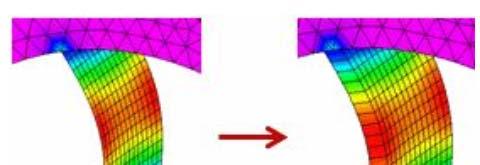
24 7. Analysis of a beam in buckling Find for four modes of buckling. Material Aluminum 6061 T6 Fixed constrain in the face shown Force 10 N in the face shown


25 7. Analysis of a beam in buckling
Learning Module 8 Shape Optimization
 Learning Module 8 Shape Optimization What is a Learning Module? Title Page Guide A Learning Module (LM) is a structured, concise, and self-sufficient learning resource. An LM provides the learner with
A New Way for Multi-piece and Multi-hit Fragment Impact Simulation Using LS-DYNA
 9 th International LS-DYNA Users Conference Impact Analysis (1) A New Way for Multi-piece and Multi-hit Fragment Impact Simulation Using LS-DYNA Xudong Xin Karagozian and Case 255 N. Hollywood Way, Suite
CAD - How Computer Can Aid Design?
 CAD - How Computer Can Aid Design? Automating Drawing Generation Creating an Accurate 3D Model to Better Represent the Design and Allowing Easy Design Improvements Evaluating How Good is the Design and
Abaqus/CAE Axisymmetric Tutorial (Version 2016)
") Abaqus/CAE Axisymmetric Tutorial (Version 2016) Problem Description A round bar with tapered diameter has a total load of 1000 N applied to its top face. The bottom of the bar is completely fixed. Determine
Abaqus/CAE Axisymmetric Tutorial (Version 2016) Problem Description A round bar with tapered diameter has a total load of 1000 N applied to its top face. The bottom of the bar is completely fixed. Determine
High bandwidth fast steering mirror
 High bandwidth fast steering mirror Presenter Francisc M. Tapos Authors:Francisc M. Tapos a, Derek J. Edinger a, Timothy R. Hilby a, Melvin S. Ni a, Buck C. Holmes b, David M. Stubbs a a Lockheed Martin
Structural Analysis of an Aluminum Spiral Staircase. EMCH 407 Final Project Presented by: Marcos Lopez and Dillan Nguyen
 Structural Analysis of an Aluminum Spiral Staircase EMCH 407 Final Project Presented by: Marcos Lopez and Dillan Nguyen Abstract An old aluminum spiral staircase at Marcos home has been feeling really
SolidWorks. An Overview of SolidWorks and Its Associated Analysis Programs
 An Overview of SolidWorks and Its Associated Analysis Programs prepared by Prof. D. Xue University of Calgary SolidWorks - a solid modeling CAD tool. COSMOSWorks - a design analysis system fully integrated
CHAPTER 4. Numerical Models. descriptions of the boundary conditions, element types, validation, and the force
 CHAPTER 4 Numerical Models This chapter presents the development of numerical models for sandwich beams/plates subjected to four-point bending and the hydromat test system. Detailed descriptions of the
Finite Element Buckling Analysis Of Stiffened Plates
 International Journal of Engineering Research and Development e-issn: 2278-067X, p-issn: 2278-800X, www.ijerd.com Volume 10, Issue 2 (February 2014), PP.79-83 Finite Element Buckling Analysis Of Stiffened
WP1 NUMERICAL BENCHMARK INVESTIGATION
 WP1 NUMERICAL BENCHMARK INVESTIGATION 1 Table of contents 1 Introduction... 3 2 1 st example: beam under pure bending... 3 2.1 Definition of load application and boundary conditions... 4 2.2 Definition
FORMING SIMULATION USING RIGID-PLASTIC MATERIAL MODEL IN MARC
 SESSION TITLE WILL BE COMPLETED BY MSC SOFTWARE FORMING SIMULATION USING RIGID-PLASTIC MATERIAL MODEL IN MARC Gary Huang, Simufact-Americas LLC April 8, 2013 SUMMARY When simulating large deformation in
2: Static analysis of a plate
 2: Static analysis of a plate Topics covered Project description Using SolidWorks Simulation interface Linear static analysis with solid elements Finding reaction forces Controlling discretization errors
Vibration Analysis with SOLIDWORKS Simulation and SOLIDWORKS. Before you start 7
 i Table of contents Before you start 7 Notes on hands-on exercises and functionality of Simulation Prerequisites Selected terminology 1: Introduction to vibration analysis 10 Differences between a mechanism
Simulation of AJWSP10033_FOLDED _ST_FR
 Phone: 01922 453038 www.hyperon-simulation-and-cad-services.co.uk Simulation of AJWSP10033_FOLDED _ST_FR Date: 06 May 2017 Designer: Study name: AJWSP10033_FOLDED_STATIC Analysis type: Static Description
Simulation of Connector Assembly C
 Simulation of Connector Assembly C Date: Sunday, March 6, 2016 Designer: Solidworks Study name: Horizontal Stress Test on C inner bend Analysis type: Static Table of Contents Model Information... 2 Study
Free-shape Optimization of a Bracket
 Free-shape Optimization of a Bracket In this exercise, shape optimization on a solid model will be performed using the free-shape optimization method along with manufacturing constraints, such as symmetry
Analysis of Detroit Seismic Joint System
 Analysis of Detroit Seismic Joint System for EMSEAL Corporation Prepared by Haig Saadetian, P.Eng. Senior Consultant ROI Engineering Inc. 50 Ronson Drive, Suite 120 Toronto ON M9W 1B3 26-April-2009 1 Contents
Simulation of RF HEat Test
 Simulation of RF HEat Test Date: Tuesday, December 22, 2015 Designer: Solidworks Study name: Stress One Third Emissivity Analysis type: Nonlinear - Dynamic Description No Data Table of Contents Description...
Simulation of Connector Assembly AA
 Simulation of Connector Assembly AA Date: Tuesday, March 1, 2016 Designer: Solidworks Study name: Horizontal Stress in AA inner tab fold Analysis type: Static Table of Contents Model Information... 2 Study
Introduction to Nastran SOL 200 Design Sensitivity and Optimization
 Introduction to Nastran SOL 200 Design Sensitivity and Optimization PRESENTED BY: CHRISTIAN APARICIO The Nastran Engineering SOL 200 questions? Lab Email me: christian@ the-engineering-lab.com Motivation
ACTUATING SYSTEMS BASED ON TWO BELLOWS
 ACTUATING SYSTEMS BASED ON TWO BELLOWS PhD Stud. Eng. Vasile Sergiu JIŞA, Technical University of Cluj-Napoca, e-mail: vasile_sergiu_jisa@yahoo.com Assist. PhD Eng. Beniamin CHETRAN, Technical University
Structural re-design of engine components
 Structural re-design of engine components Product design cycle Design Development Testing Structural optimization Product knowledge Design freedom 2/18 Structural re-design of engine components Product
PTC Creo Simulate. Features and Specifications. Data Sheet
 PTC Creo Simulate PTC Creo Simulate gives designers and engineers the power to evaluate structural and thermal product performance on your digital model before resorting to costly, time-consuming physical
Chapter 5 Modeling and Simulation of Mechanism
 Chapter 5 Modeling and Simulation of Mechanism In the present study, KED analysis of four bar planar mechanism using MATLAB program and ANSYS software has been carried out. The analysis has also been carried
Exercise 1. 3-Point Bending Using the GUI and the Bottom-up-Method
 Exercise 1 3-Point Bending Using the GUI and the Bottom-up-Method Contents Learn how to... 1 Given... 2 Questions... 2 Taking advantage of symmetries... 2 A. Preprocessor (Setting up the Model)... 3 A.1
ME Optimization of a Frame
 ME 475 - Optimization of a Frame Analysis Problem Statement: The following problem will be analyzed using Abaqus. 4 7 7 5,000 N 5,000 N 0,000 N 6 6 4 3 5 5 4 4 3 3 Figure. Full frame geometry and loading
CHAPTER 8 FINITE ELEMENT ANALYSIS
 If you have any questions about this tutorial, feel free to contact Wenjin Tao (w.tao@mst.edu). CHAPTER 8 FINITE ELEMENT ANALYSIS Finite Element Analysis (FEA) is a practical application of the Finite
ME 475 FEA of a Composite Panel
 ME 475 FEA of a Composite Panel Objectives: To determine the deflection and stress state of a composite panel subjected to asymmetric loading. Introduction: Composite laminates are composed of thin layers
Module 1.3W Distributed Loading of a 1D Cantilever Beam
 Module 1.3W Distributed Loading of a 1D Cantilever Beam Table of Contents Page Number Problem Description 2 Theory 2 Workbench Analysis System 4 Engineering Data 5 Geometry 6 Model 11 Setup 13 Solution
ABOUT FEATURES OF SIMULATION MODULE IN SOLIDWORKS
 ABOUT FEATURES OF SIMULATION MODULE IN SOLIDWORKS prof.phd.eng. Cătălin IANCU Engineering and Sustainable Development Faculty, C-tin Brâncuşi Univ. of Tg-Jiu, ciancu@utgjiu.ro Abstract: In this paper are
Exercise 1. 3-Point Bending Using the Static Structural Module of. Ansys Workbench 14.0
 Exercise 1 3-Point Bending Using the Static Structural Module of Contents Ansys Workbench 14.0 Learn how to...1 Given...2 Questions...2 Taking advantage of symmetries...2 A. Getting started...3 A.1 Choose
Separation Connector. Analysis of Final Design Concepts Document
 Separation Connector By Koll Christianson, Amelia Fuller, Luis Herrera, Zheng Lian, and Shaun Shultz Team 19 Analysis of Final Design Concepts Document Submitted towards partial fulfillment of the requirements
Finite Element Analysis Using Creo Simulate 4.0
 Introduction to Finite Element Analysis Using Creo Simulate 4.0 Randy H. Shih SDC PUBLICATIONS Better Textbooks. Lower Prices. www.sdcpublications.com Powered by TCPDF (www.tcpdf.org) Visit the following
Revised Sheet Metal Simulation, J.E. Akin, Rice University
 Revised Sheet Metal Simulation, J.E. Akin, Rice University A SolidWorks simulation tutorial is just intended to illustrate where to find various icons that you would need in a real engineering analysis.
MAE Advanced Computer Aided Design. 01. Introduction Doc 02. Introduction to the FINITE ELEMENT METHOD
 MAE 656 - Advanced Computer Aided Design 01. Introduction Doc 02 Introduction to the FINITE ELEMENT METHOD The FEM is A TOOL A simulation tool The FEM is A TOOL NOT ONLY STRUCTURAL! Narrowing the problem
Appendix A: Mesh Nonlinear Adaptivity. ANSYS Mechanical Introduction to Structural Nonlinearities
 Appendix A: Mesh Nonlinear Adaptivity 16.0 Release ANSYS Mechanical Introduction to Structural Nonlinearities 1 2015 ANSYS, Inc. Mesh Nonlinear Adaptivity Introduction to Mesh Nonlinear Adaptivity Understanding
The part to be analyzed is the bracket from the tutorial of Chapter 3.
 Introduction to Solid Modeling Using SolidWorks 2007 COSMOSWorks Tutorial Page 1 In this tutorial, we will use the COSMOSWorks finite element analysis (FEA) program to analyze the response of a component
ANALYSIS AND OPTIMIZATION OF FLYWHEEL
 Int. J. Mech. Eng. & Rob. Res. 2012 Sushama G Bawane et al., 2012 Research Paper ISSN 2278 0149 www.ijmerr.com Vol. 1, No. 2, July 2012 2012 IJMERR. All Rights Reserved ANALYSIS AND OPTIMIZATION OF FLYWHEEL
SDC. Engineering Analysis with COSMOSWorks. Paul M. Kurowski Ph.D., P.Eng. SolidWorks 2003 / COSMOSWorks 2003
 Engineering Analysis with COSMOSWorks SolidWorks 2003 / COSMOSWorks 2003 Paul M. Kurowski Ph.D., P.Eng. SDC PUBLICATIONS Design Generator, Inc. Schroff Development Corporation www.schroff.com www.schroff-europe.com
CHAPTER-10 DYNAMIC SIMULATION USING LS-DYNA
 DYNAMIC SIMULATION USING LS-DYNA CHAPTER-10 10.1 Introduction In the past few decades, the Finite Element Method (FEM) has been developed into a key indispensable technology in the modeling and simulation
About the Author. Acknowledgements
 About the Author Dr. Paul Kurowski obtained his MSc and PhD in Applied Mechanics from Warsaw Technical University. He completed postdoctoral work at Kyoto University. Dr. Kurowski is an Assistant Professor
Simula ons with NX. HANSER Hanser Publishers, Munich Hanser Publica ons, Cincinna
 Reiner Anderl Peter Binde Simula ons with NX Kinema cs, FEA, CFD, EM and Data Management. With numerous examples of NX 9 Color Plots Book ISBN 978-1-56990-479-4 HANSER Hanser Publishers, Munich Hanser
Spur Gears Static Stress Analysis with Linear Material Models
 Exercise A Spur Gears Static Stress Analysis with Linear Material Models Beam and Brick Elements Objective: Geometry: Determine the stress distribution in the spur gears when a moment of 93.75 in-lb is
SOLIDWORKS Simulation
 SOLIDWORKS Simulation Length: 3 days Prerequisite: SOLIDWORKS Essentials Description: SOLIDWORKS Simulation is designed to make SOLIDWORKS users more productive with the SOLIDWORKS Simulation Bundle. This
Efficient Shape Optimisation of an Aircraft Landing Gear Door Locking Mechanism by Coupling Abaqus to GENESIS
 Efficient Shape Optimisation of an Aircraft Landing Gear Door Locking Mechanism by Coupling Abaqus to GENESIS Mark Arnold and Martin Gambling Penso Consulting Ltd GRM Consulting Ltd Abstract: The objective
Lesson: Static Stress Analysis of a Connecting Rod Assembly
 Lesson: Static Stress Analysis of a Connecting Rod Assembly In this tutorial we determine the effects of a 2,000 pound tensile load acting on a connecting rod assembly (consisting of the rod and two pins).
OPTIMIZATION OF ENERGY DISSIPATION PROPERTY OF ECCENTRICALLY BRACED STEEL FRAMES
 OPTIMIZATION OF ENERGY DISSIPATION PROPERTY OF ECCENTRICALLY BRACED STEEL FRAMES M. Ohsaki (Hiroshima Univ.) T. Nakajima (Kyoto Univ. (currently Ohbayashi Corp.)) Background Difficulty in optimization
Module 1.2: Moment of a 1D Cantilever Beam
 Module 1.: Moment of a 1D Cantilever Beam Table of Contents Page Number Problem Description Theory Geometry Preprocessor 6 Element Type 6 Real Constants and Material Properties 7 Meshing 9 Loads 10 Solution
EN1740 Computer Aided Visualization and Design Spring /26/2012 Brian C. P. Burke
 EN1740 Computer Aided Visualization and Design Spring 2012 4/26/2012 Brian C. P. Burke Last time: More motion analysis with Pro/E Tonight: Introduction to external analysis products ABAQUS External Analysis
FEA Simulation Approach for Braking Linkage: A Comparison through Cross-section Modification
 International Journal of Mechanics and Solids. ISSN 0973-1881 Volume 12, Number 1 (2017), pp. 1-13 Research India Publications http://www.ripublication.com/ijms.htm FEA Simulation Approach for Braking
Lab#5 Combined analysis types in ANSYS By C. Daley
 Engineering 5003 - Ship Structures I Lab#5 Combined analysis types in ANSYS By C. Daley Overview In this lab we will model a simple pinned column using shell elements. Once again, we will use SpaceClaim
INTERNSHIP REPORT Analysis of a generic lifting table Ruben Teunis s Mechanical Engineering Applied Mechanics, CTW
 INTERNSHIP REPORT Analysis of a generic lifting table Ruben Teunis s1112392 Mechanical Engineering Applied Mechanics, CTW 25-08-2014 5-12-2014 Enschede, The Netherlands Supervisor: T. Tinga Hengelo, The
Contents Metal Forming and Machining Processes Review of Stress, Linear Strain and Elastic Stress-Strain Relations 3 Classical Theory of Plasticity
 Contents 1 Metal Forming and Machining Processes... 1 1.1 Introduction.. 1 1.2 Metal Forming...... 2 1.2.1 Bulk Metal Forming.... 2 1.2.2 Sheet Metal Forming Processes... 17 1.3 Machining.. 23 1.3.1 Turning......
Embedded Reinforcements
 Embedded Reinforcements Gerd-Jan Schreppers, January 2015 Abstract: This paper explains the concept and application of embedded reinforcements in DIANA. Basic assumptions and definitions, the pre-processing
TABLE OF CONTENTS WHAT IS ADVANCE DESIGN? INSTALLING ADVANCE DESIGN... 8 System requirements... 8 Advance Design installation...
 Starting Guide 2019 TABLE OF CONTENTS INTRODUCTION... 5 Welcome to Advance Design... 5 About this guide... 6 Where to find information?... 6 Contacting technical support... 6 WHAT IS ADVANCE DESIGN?...
Analysis Steps 1. Start Abaqus and choose to create a new model database
 Source: Online tutorials for ABAQUS Problem Description The two dimensional bridge structure, which consists of steel T sections (b=0.25, h=0.25, I=0.125, t f =t w =0.05), is simply supported at its lower
COMPUTER AIDED ENGINEERING. Part-1
 COMPUTER AIDED ENGINEERING Course no. 7962 Finite Element Modelling and Simulation Finite Element Modelling and Simulation Part-1 Modeling & Simulation System A system exists and operates in time and space.
MIDAS/FEA. Advanced Nonlinear and Detailed Analysis Program. MIDAS Information Technology Co., Ltd.
 MIDAS/FEA Advanced Nonlinear and Detailed Analysis Program Analysis Capabilities Static Analysis Construction Stage Analysis Moving Load Analysis Modal Analysis Linear Buckling Analysis Transient / Frequency
ME 345: Modeling & Simulation. Introduction to Finite Element Method
 ME 345: Modeling & Simulation Introduction to Finite Element Method Examples Aircraft 2D plate Crashworthiness 2 Human Heart Gears Structure Human Spine 3 F.T. Fisher, PhD Dissertation, 2002 Fluid Flow
Simulation of Fully extended LM-14-8-FM- 500LB tests
 LLC www.larsonelectronics.com sales@larsonelectronics.com 9419 E US HWY 175, Kemp, TX 75143 - P: (800) 369-6671 - F: (903) 498-3364 Simulation of Fully extended LM-14-8-FM- 500LB tests Date: Friday, November
ANSYS User s Group Non-Linear Adaptive Meshing (NLAD)
") 19.2 Release ANSYS User s Group Non-Linear Adaptive Meshing (NLAD) Sriraghav Sridharan Application Engineer, ANSYS Inc Sriraghav.Sridharan@ansys.com 1 2017 ANSYS, Inc. October 10, 2018 Topics Background
19.2 Release ANSYS User s Group Non-Linear Adaptive Meshing (NLAD) Sriraghav Sridharan Application Engineer, ANSYS Inc Sriraghav.Sridharan@ansys.com 1 2017 ANSYS, Inc. October 10, 2018 Topics Background
Abstract. Introduction:
 Abstract This project analyzed a lifecycle test fixture for stress under generic test loading. The maximum stress is expected to occur near the shrink fit pin on the lever arm. The model was constructed
ECE421: Electronics for Instrumentation
 ECE421: Electronics for Instrumentation Lecture #8: Introduction to FEA & ANSYS Mostafa Soliman, Ph.D. March 23 rd 2015 Mostafa Soliman, Ph.D. 1 Outline Introduction to Finite Element Analysis Introduction
WORKSHOP 6.3 WELD FATIGUE USING NOMINAL STRESS METHOD. For ANSYS release 14
 WORKSHOP 6.3 WELD FATIGUE USING NOMINAL STRESS METHOD For ANSYS release 14 Objective: In this workshop, a weld fatigue analysis on a VKR-beam with a plate on top using the nominal stress method is demonstrated.
Nerf Blaster Redesign
 Nerf Blaster Redesign ME4041 Computer Graphics and CAD April 0, 010 Submitted By: Michael Schulman Greg Mann Table of Contents Introduction. Objectives Modeling. 4 External Components 4 Internal Components.
SCIA stands for scientific analyser. The C in SCIA Engineering is not pronounced. Note that the first c in science is not pronounced either.
 Design of a reinforced concrete 4-hypar shell with edge beams P.C.J. Hoogenboom, 22 May 2016 SCIA stands for scientific analyser. The C in SCIA Engineering is not pronounced. Note that the first c in science
Static Stress Analysis
 Static Stress Analysis Determine stresses and displacements in a connecting rod assembly. Lesson: Static Stress Analysis of a Connecting Rod Assembly In this tutorial we determine the effects of a 2,000-pound
Similar Pulley Wheel Description J.E. Akin, Rice University
 Similar Pulley Wheel Description J.E. Akin, Rice University The SolidWorks simulation tutorial on the analysis of an assembly suggested noting another type of boundary condition that is not illustrated
Introduction to Abaqus. About this Course
 Introduction to Abaqus R 6.12 About this Course Course objectives Upon completion of this course you will be able to: Use Abaqus/CAE to create complete finite element models. Use Abaqus/CAE to submit and
Getting Started. These tasks should take about 20 minutes to complete. Getting Started
 Getting Started Getting Started This tutorial will guide you step-by-step through your first ELFINI and Generative Part Structural Analysis session, allowing you to get acquainted with the product. You
Impact and Postbuckling Analyses
 ABAQUS/Explicit: Advanced Topics Lecture 8 Impact and Postbuckling Analyses ABAQUS/Explicit: Advanced Topics L8.2 Overview Geometric Imperfections for Postbuckling Analyses ABAQUS/Explicit: Advanced Topics
FEA Applications I MET 415 Review Course Structure: 15 week course Weekly Schedule 50 minute lecture 2.5 hour laboratory 50 minute lecture
 FEA Applications I MET 415 Review Course Structure: 15 week course Weekly Schedule 50 minute lecture 2.5 hour laboratory 50 minute lecture Goal: Obtain feedback from Industry Users on course presentation
Analysis of Fluid-Structure Interaction Effects of Liquid-Filled Container under Drop Testing
 Kasetsart J. (Nat. Sci.) 42 : 165-176 (2008) Analysis of Fluid-Structure Interaction Effects of Liquid-Filled Container under Drop Testing Chakrit Suvanjumrat*, Tumrong Puttapitukporn and Satjarthip Thusneyapan
Creo Simulate 3.0 Tutorial
 Creo Simulate 3.0 Tutorial Structure and Thermal Roger Toogood, Ph.D., P. Eng. SDC PUBLICATIONS Better Textbooks. Lower Prices. www.sdcpublications.com Powered by TCPDF (www.tcpdf.org) Visit the following
Numerical Simulation of Elastic-Plastic Deformation of Aircraft Fuel Tank Access Cover Impacted by Tyre Fragment
 Numerical Simulation of Elastic-Plastic Deformation of Aircraft Fuel Tank Access Cover Impacted by Tyre Fragment Alexander A. Ryabov, Vladimir I. Romanov, Sergey S. Kukanov, Anatoliy K. Botvinkin Sarov
Engineering Analysis
 Engineering Analysis with SOLIDWORKS Simulation 2018 Paul M. Kurowski SDC PUBLICATIONS Better Textbooks. Lower Prices. www.sdcpublications.com Powered by TCPDF (www.tcpdf.org) Visit the following websites
Elastic Stability of a Plate
 WORKSHOP PROBLEM 7 Elastic Stability of a Plate Objectives Produce a Nastran input file. Submit the file for analysis in MSC/NASTRAN. Find the first five natural modes of the plate. MSC/NASTRAN 101 Exercise
FB-MULTIPIER vs ADINA VALIDATION MODELING
 FB-MULTIPIER vs ADINA VALIDATION MODELING 1. INTRODUCTION 1.1 Purpose of FB-MultiPier Validation testing Performing validation of structural analysis software delineates the capabilities and limitations
Multi-Step Analysis of a Cantilever Beam
 LESSON 4 Multi-Step Analysis of a Cantilever Beam LEGEND 75000. 50000. 25000. 0. -25000. -50000. -75000. 0. 3.50 7.00 10.5 14.0 17.5 21.0 Objectives: Demonstrate multi-step analysis set up in MSC/Advanced_FEA.
Non-Linear Analysis of Base Plates in Automated Storage Systems
 Non-Linear Analysis of Base Plates in Automated Storage Systems Ph.D. Juan José del Coz Díaz, Fco. Suarez Domínguez, Paulino J.Garcia Nieto University of Oviedo. Construction and Applied Mathematics Area.
Advanced Professional Training
 Advanced Professional Training Non Linea rand Stability All information in this document is subject to modification without prior notice. No part of this manual may be reproduced, stored in a database
Course in ANSYS. Example0153. ANSYS Computational Mechanics, AAU, Esbjerg
 Course in Example0153 Example Offshore structure F Objective: Display the deflection figure and von Mises stress distribution Tasks: Import geometry from IGES. Display the deflection figure? Display the
Abaqus CAE Tutorial 6: Contact Problem
 ENGI 7706/7934: Finite Element Analysis Abaqus CAE Tutorial 6: Contact Problem Problem Description In this problem, a segment of an electrical contact switch (steel) is modeled by displacing the upper
THREE DIMENSIONAL DYNAMIC STRESS ANALYSES FOR A GEAR TEETH USING FINITE ELEMENT METHOD
 THREE DIMENSIONAL DYNAMIC STRESS ANALYSES FOR A GEAR TEETH USING FINITE ELEMENT METHOD Haval Kamal Asker Department of Mechanical Engineering, Faculty of Agriculture and Forestry, Duhok University, Duhok,
Common Mistakes And Errors In Modelling
 Common Mistakes And Errors In Modelling The modeling pitfalls listed below can be considered as appetizers with the intention of making you think (and worry) more about the model set-up. More in-depth
Introduction to Engineering Analysis
 Chapter 1 Introduction to Engineering Analysis This chapter introduces you to the Stress Analysis and Dynamic Simulation environments. You learn how digital prototyping can be used to simulate your designs
Topology Optimization and Analysis of Crane Hook Model
 RESEARCH ARTICLE Topology Optimization and Analysis of Crane Hook Model Thejomurthy M.C 1, D.S Ramakrishn 2 1 Dept. of Mechanical engineering, CIT, Gubbi, 572216, India 2 Dept. of Mechanical engineering,
PLM Software. Femap Express for Solid Edge. Answers for industry. Velocity Series
 Velocity Series Femap Express for Solid Edge www.siemens.com/solidedge w h i t e p a p e r Preconfigured, best-practice, process guidance for simple finite element analysis. PLM Software Answers for industry.
1. INTRODUCTION. A shell may be defined as the solid material enclosed. between two closely spaced curved surfaces (1), the distance
, the distance") 1 1. INTRODUCTION 1.1. GENERAL A shell may be defined as the solid material enclosed between two closely spaced curved surfaces (1), the distance between these two surfaces being the thickness of the shell.
1 1. INTRODUCTION 1.1. GENERAL A shell may be defined as the solid material enclosed between two closely spaced curved surfaces (1), the distance between these two surfaces being the thickness of the shell.
Finite element method - tutorial no. 1
 Martin NESLÁDEK Faculty of mechanical engineering, CTU in Prague 11th October 2017 1 / 22 Introduction to the tutorials E-mail: martin.nesladek@fs.cvut.cz Room no. 622 (6th floor - Dept. of mechanics,
Coupled Analysis of FSI
 Coupled Analysis of FSI Qin Yin Fan Oct. 11, 2008 Important Key Words Fluid Structure Interface = FSI Computational Fluid Dynamics = CFD Pressure Displacement Analysis = PDA Thermal Stress Analysis = TSA
Analysis of a silicon piezoresistive pressure sensor
 Analysis of a silicon piezoresistive pressure sensor This lab uses the general purpose finite element solver COMSOL to determine the stress in the resistors in a silicon piezoresistive pressure sensor
DMU Engineering Analysis Review
 DMU Engineering Analysis Review Overview Conventions What's New? Getting Started Entering DMU Engineering Analysis Review Workbench Generating an Image Visualizing Extrema Generating a Basic Analysis Report
FEM-Analysis of a Column Crane with FEM-System MEANS V10. Website: Phone:
 FEM-Analysis of a Column Crane with FEM-System MEANS V10 Website: www.fem-infos.com Email: info@fem-infos.com Phone: 0049-7844 - 98 641 Part 19: FEM-Analysis of a Column Crane with MEANS V10 1 Part 19:
An Overview of Computer Aided Design and Finite Element Analysis
 An Overview of Computer Aided Design and Finite Element Analysis by James Doane, PhD, PE Contents 1.0 Course Overview... 4 2.0 General Concepts... 4 2.1 What is Computer Aided Design... 4 2.1.1 2D verses
Types of Idealizations. Idealizations. Cylindrical Shaped Part. Cyclic Symmetry. 3D Shell Model. Axisymmetric
 Types of Idealizations Idealizations Selecting the model type 3D Solid Plane Stress Plane Strain 3D Shell Beam Cyclic Symmetry Cylindrical Shaped Part Interior Pressure Load 3D model can be used to model
Shell-to-Solid Element Connector(RSSCON)
") WORKSHOP 11 Shell-to-Solid Element Connector(RSSCON) Solid Shell MSC.Nastran 105 Exercise Workbook 11-1 11-2 MSC.Nastran 105 Exercise Workbook WORKSHOP 11 Shell-to-Solid Element Connector The introduction
WORKSHOP 11 Shell-to-Solid Element Connector(RSSCON) Solid Shell MSC.Nastran 105 Exercise Workbook 11-1 11-2 MSC.Nastran 105 Exercise Workbook WORKSHOP 11 Shell-to-Solid Element Connector The introduction
#SEU Welcome! Solid Edge University 2016
 #SEU 2016 Welcome! Solid Edge University 2016 Realize innovation. Fundamental Simulation Capabilities in Solid Edge Craig Ruchti, Solid Edge Global Technical Business Development Realize innovation. Fundamental
Outline. 3 Linear Analysis 3.1 Analysis commands 3.2 Results. Box Girder Bridge 2/28
 ANALYS: linear static. CONSTR: suppor. ELEMEN: bar hx24l reinfo solid tp18l. LOAD: elemen face force prestr reinfo weight. MATERI: elasti isotro. OPTION: direct. POST: binary ndiana. PRE: dianai. RESULT:
Topology Optimization Requirements in the Age of Additive Manufacturing
 Topology Optimization Requirements in the Age of Additive Manufacturing Dr. Andreas Vlahinos Principal at Advanced Engineering Solutions andreas@aes.nu Topology Optimization Roundtable Hilton Crystal City