Chapter 4 Microscopy
|
|
|
- Shanna Greer
- 6 years ago
- Views:
Transcription

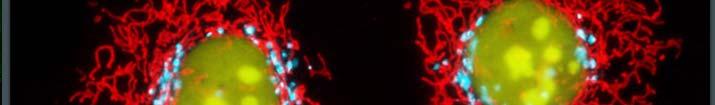
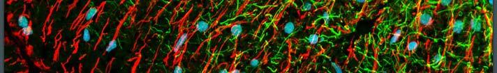
1 Chapter 4 Microscopy Gabriel Popescu University of Illinois at Urbana Champaign Beckman Institute Quantitative Light Imaging Laboratory Principles of Optical Imaging Electrical and Computer Engineering, UIUC
2 4.1 Resolution of Optical Microscopes The Microscope can be approximated by 2 lenses F [ F [ U [ x, y ]]] Sample U(x,y) Objective F 2 F 1 Tube lens FUxy [ [, ]] x y 1 F2 [ F1 [ U [ xy, ]]] U [, ] M M sign means inverted image The objective isthe mostimportantpart part of the microscope Usually a third lens (ocular) images F 2 at, such that we can visualize it with the relaxed eye. F 2 2
3 4.1 Resolution of Optical Microscopes The objective lens dictates the resolution or size of the smallest object that the microscope can resolve. Contrast is generated by absorption, scattering, etc. Microscopes can be categorized by the methods that they use to produce contrast. Let s consider an infinitely smallobject (point): x 1 x 2 x M θ M How small can we see? f f 3
4 4.1 Resolution of Optical Microscopes Fourier properties p of the lens; the reconstructed field is: 2 i ( x1ξ y1) U[ x, y] U[, ] e d d M M We know that ξ and because ξ and x f (4.1) We can access only a finite frequency range and therefore we can only achieve finite resolution. We would need an infinite spectrum to reconstruct a d function (in this case a point) M y M f 4
5 4.1 Resolution of Optical Microscopes Given the finite frequency support we can write: U [, ] U [, ] H [, ] Where H M 1 if ξ ξ, { 0 otherwise M (4.2) 1 ξ ξ ξ ξ So, eq. 4.1 becomes Uxy [, ] FU [ [, ] H [, ]] (4.3) 5
6 4.1 Resolution of Optical Microscopes Use the Convolution Theorem once more (which states that convolution in one domain is multiplication in another) to get: Uxy [, ] Uxy [, ] V hxy [, ] Uxy [, ] Where is the microscope image Uxy [, ] is the ideal image hxy [, ] isthe impulse response e i ( x ξ y ) (4.4) (4.5) hxy [, ] FH [ [, ]] L x y [, ] [ ] 1 if f f w H fx f y 0 otherwise circ w 2w p (4.6) 6
7 4.1 Resolution of Optical Microscopes J [2 W ] 2 W 1 So, F[ H ] A h, J 1 So the image of a point becomes: where is a Bessel function of the 1st kind and order 2 2 J [2 ] 1 W h [ x, y ] A 2 W (4.7) M Since W and so, M x M x 2W M 1.22 f f.61 f x M (eq. 4.8) [ ] 1 2 J x x A point will be imaged as a smeared spot of diameter 1.22 x H The Airy Function.61 f x M 7
8 4.1 Resolution of Optical Microscopes Imagine that we have two such points. Then the resolution is the minimum distance between the points that are separated, which is ρ. ρ = resolution An objective lens that allows higher spatial frequencies (or angles) provides a higher resolution. 8
9 4.1 Resolution of Optical Microscopes Ob x 1 Ob x x M 1 2 x M 2 S S f1 1 M Definition: sin1 tan x 1 f 1 f f2 f2 sin NA Numerical Aperture (4.10).61 NA 2NA The resolution becomes but is good enough Compare Ob 1 and Ob 2 above:, x x NA NA (4.11) 1 2 M 1 M So Ob 2 provides a better resolution. 9
10 4.1 Resolution of Optical Microscopes In general, objectives are made out of several lenses => complex systems P P ' F f W f Entrance Pupil Objective focal distance measured from principal plane W working distance = distance from F to physical surface of lens Entrance Pupil = image of physical aperture f and entrance pupil determine numerical aperture i.e. resolution 10
11 4.1 Resolution of Optical Microscopes Note: if the objective lens is immersed in a medium for which n 1, then NA nna (4.12) n This means that it is possible for immersed objective lenses to have a better resolution. 11
12 4.2 Contrast Ixy [, ] The final image consists of a distribution which is the result of absorption, scattering/diffraction, etc. Contrast = a measure of the intensity fluctuations across the image. In general, the more contrast tthe better. Low Contrast High Contrast I I x x demo available 12
13 4.2 Contrast Microscope image 2 regions of interest: A, B N is the background noise (in sample) (4.13) Contrast : C S S ; S = signal A, B AB A B A, B Contrast to noise ratio: CNR N AB C AB N S A = standard deviation of noise. 2 2 N i i i N S B ( S S) ; S = signal in pixels 13
14 4.2 Contrast While resolution is given by the instrument, the contrast is given by the instrument/sample combination. Most biological structures (i.e. cells) are very transparent so I[ xy, ] is flat, which means there is low contrast They can be assumed phase objects Example of a phase object: Wave front I[ xy, ] N= nm k Imaging system Glass Profile Phase Grating 14
15 4.2 Contrast No absorption so I [ x, y ] constant contrast = 0 BUT: the wave front carries information about the sample Exy [, ] E e i [ x, y] (4.14) This is the expression for the field in the vicinity of a phase object. Bright Field microscopy produces low contrast images of phase objects 0 15
16 4.2 Contrast There are several ways to enhance contrast: Endogeneous Contrast Dark field Phase contrast Schlerein Quantitative phase microscopy Confocal Endogeneous florescence Exogeneous Contrast Agents Staining Florescent tagging Full field Confocal More recently Beads (dielectric and metallic) Nano Quantum Dots 16
17 4.3 Dark Field Microscopy Consider the low contrast image I(x) I(x,y) x Typical low pass filtering = remove C I(x) I(fx) x Fourier Remove low Frequency fx Then take the inverse Fourier Transformation Inverse Fourier I(x) x High Contrast 17
18 4.3 Dark Field Microscopy Actual Microscope Object f Lens Blocks low frequency High frequency components are enhanced (eg. (gedges) Without the sample Dark Field Enhanced Contrast 18
19 4.4 Schlerein Method Not used very often nowadays Blocks ½ spectrum Image Plane Fourier Inverse Fourier Enhances Contrast Phase objects can be rendered visible Edges are enhanced Relates to Hilbert Transform. 19
 Fourier F(g) Ft(g) f(x) ~ fx () and 1 P f( x') f () x f() x i dx' 2")

20 4.4 Schlieren Method Exercise: Show the following for a real signal f(x) Cut ½ spectrum Inverse Fourier f(x) Fourier F(g) Ft(g) f(x) ~ fx () and 1 P f( x') f () x f() x i dx' 2 2 xx' Hilbert To the left: David Hilbert a German Mathematician, recognized as one of the most influential and universal mathematicians of the 19th and early 20th centuries. 20
21 4.5 PhaseContrast Microscopy Developed by Frits Zernike (1935) yielding Noble prize in 1953(Physics) Very powerful, commonly used today. Consider a phase object: U( x, y) i ( x, y) e (4.15) Intensity distribution: I( x, y) U 2 1 No Contrast Assume: The microscope has a magnification M=1 (x,y) (x,y ) S Fourier Plane Image plane 21
22 4.5 PhaseContrast Microscopy x y i2 ( f f ) U ( fx, fy) U( x, y) e dxdy (4.16) f x x f ; f x y f U U x y dxdy (4.17) Note: (0,0) (, ) Central Ordinate Theorem Zero Frequency component corresponds to a plane wave in Plane Wave the image plane(constant of (x,y)) Uxydxdy (, ) U0 1 A U( x, y) dxdy 22
23 Note: 4.5 PhaseContrast Microscopy has no information i about the structure of the sample. U 0 1 U0 U ( x, y ) dxdy A = Average field Imageformation is an interference between the average field and high frequency components. Uxy (, ) U [ Uxy (, ) U ] 0 0 High Frequency Component U ( x, y ) 1 (4.18) 23
24 4.5 PhaseContrast Microscopy Phase contrast relies on shifting the phase of U 0 by U i U ae 0 0 i Assume ; U U ae becomes: U The intensity distribution in the imageplane becomes: 2 I( x, y) U( x, y) i i( x, y) 2 ae e 1 2 i( ) i i a ae ae e 1 1 Re[2 2 2 ] i U( x, y) ae [ U( x, y) 1] (4.19) 2 a 2[1 acos cosacos( )] (4.20) 24
25 4.5 PhaseContrast Microscopy Note: For a = 0 recover Dark Field Microscopy Assume small phase shift cos 1; 2 2 I( x, y) a 2a sin sin 2 a a x y 2 (, ) sin 2 I( x, y) a 2 a ( x, y) (4.21) PC couples into intensity a<1 enhances contrast (best modulationfor U U )
26 4.6 Nomarski/Differential Interference Contrast Microscopy DIC= Differential Interference Contrast P 1 1 Condenser x 1 1 Movable Wollaston S Obj. Wollaston Prism #1 Wollaston Prism #2 Use polarization discrimination to create 2 interfering beams Illuminate sample(s) with 2 drifted beams 26
27 4.6 Nomarski/Differential Interference Contrast Microscopy Shift amount Airy disk 2NA Wollaston prism #2 brings the 2 beams together through interference. E E E A e A e Total i 1 i (4.22) l l d. d. l d 1 0 n1 k n0 d k cos 27
28 4.6 Nomarski/Differential Interference Contrast Microscopy By varying the position of Wollaston prism one can adjust 1 0 Phase Shift through the sample: dx l. x i ( x dx) e i ( x) z e S becomes: E A e A e Total Ae i( n ) i0 n i0 i( 110) 0 e [1 e ] 0 (4.23) 28
29 4.6 Nomarski/Differential Interference Contrast Microscopy The Intensity in the image plane (as a function of displacement x). Ix () 2 I(1cos[( xdx) () x]) 0 Note: For small, best results obtained for I( x) 2 I (1 sin[ ( xdx) ( x)]) 0 (4.24) 2 (4.25) ( xdx) ( x) 2 I0[1 dx ] dx So the final intensity i distribution ib i is related to the gradient of the phase: ( x) x 29
30 4.6 Nomarski/Differential Interference Contrast Microscopy DIC is a very sensitive to edges, even though the actual phase shifts are small. Example: sample x x Intensity no contrast Phase contrast tand DIC heavily used today, especially ill for investigating live biological structures (cells) noninvasively. x 30
31 4.7 QuantitativePhaseMicroscopy PC &DIC are great, but qualitative in terms of phase Knowing ( xy, ) quantitatively i offers some advantages, i.e. gives a map of structure density; for homogeneous structures, gives molecular information. QPM is a rather new domain; several methods so far. Main obstacle is noise 31
32 4.8 Confocal Microscopy So far, we discussed full field imaging, i.e obtaining the entire image at once(great feature: imaging as a parallel process). The image can be recorded point by point also(like TV), sometimes with some advantages. Confocal = same focal point for illumination and collection Pinhole 32
33 4.8 Confocal Microscopy Due to pinhole, light out of focus is rejected, which can create stacks of slices, hence 3D rendering Scanning: either by scanning the sample or the beam Note: 3D Info large field of view (limited by aperture) up to 2 better resolution! It works in reflection usually BS Pinhole 33
34 4.8 Confocal Microscopy/ NSOM Recent development: Multi Foci Improves acquisition iii time Need more power Trade off Multiple Focused beam Confocal can provide many frames/seconds(video rate) Leading to 4D imaging(x,y,z,t) 34
35 4.8 Confocal Microscopy/ NSOM Near Field Scanning Optical Microscope(NSOM) Continuation i of confocal l& AFM Tappered fiber as cantilever : Fiber Aperture down to 50 nm Evanescent waves (no transmission in air) 35
36 4.8 Confocal Microscopy/ NSOM Sample nm D Evanescent waves couple into sample Became propagating Not limited dby dff diffraction Drawback: scanning time; difficult in liquids 36
37 4.9 Fluorescence Microscopy Illumination and emission have different wavelengths Endogenous Fluorophoress eg. NADH Most commonly exogenous Recently: GFP technology (given fluorescent protein) geneticallyencoded encoded, fused with DNA GFP live cell imaging allowsfor multiple fluorophores dynamic monitoring of processes(cell signaling) 37
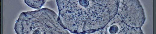
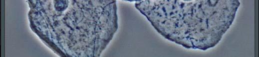
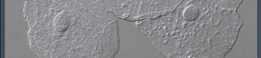
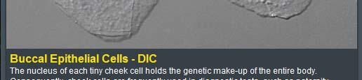
38 4.9 Fluorescence Microscopy Fluorescence adds specificity to the measurement. (organelledynamics dynamics, process specific) Typically epi fluorescence( reflection geometry) Obj. S < BS Filter Filter blocks the excitation light 38
39 4.9 Fluorescence Microscopy Full Field is limited to thin samples Combine fluorescence & confocal leads to deeper penetration Issues when imaging live cells: acquisition time, sensitivity, damage. Photo bleaching can produce cell damage: limit duration of illumination need efficiency sensitivity use intensified ifi CCD Acquisition speed: improve with multi foci &Nipkow disk scanning 39
40 4.9 Fluorescence Microscopy Other Fluorescence Techniques: Total linternal reflection FCS Fluorescence correlation spectroscopy FRAP Fluorescence recovery after photobleaching FRET Fluorescence resonance energy transfer. FLIM fluorescence lifetime imaging. g STED Stimulated emission depletion 100nm spot STED+ 4Pi confocal microscopy 33nm diffraction spot single molecule imaging. PALM, fpalm Fiona, etc 40
41 4.10 Multiphoton Imaging 2 Photon laser scanning microscopy Nonlinear process Deep Penetration Requires high power density 1 I f I 2 x Improves Resolution 2 Illumination spot is reduce by z 0 Fluorescence = 41
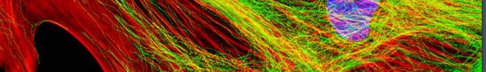
42 4.10 Multiphoton Imaging 2nd harmonic Imaging recent: Endogenous SHG molecules(e.g l collagen) ( L) 2 P E coherent process (phase matching) Same advantage of smaller illumination spot Let s take a look at examples! 42
43 Microscopy images Nikon


44


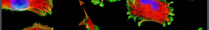
45 1. Cell imaging
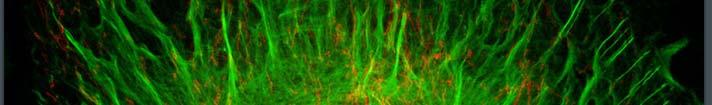
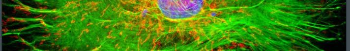
46 Fluorescence microscopy Nikon


47


48


49


50


51


52


53


54

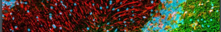
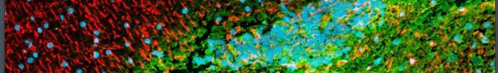
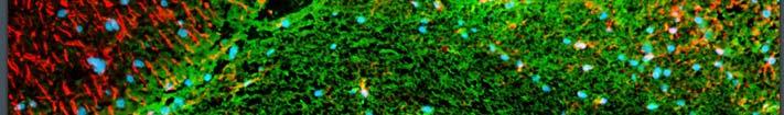
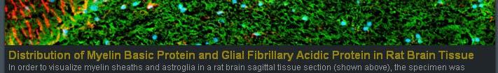
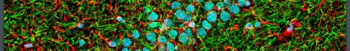
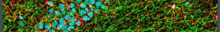
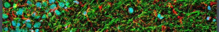
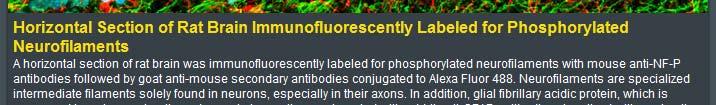
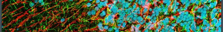
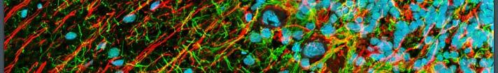
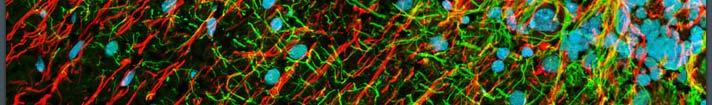
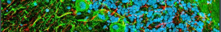
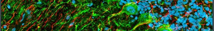
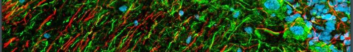
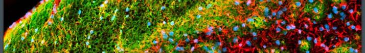
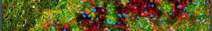
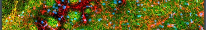
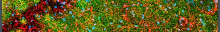
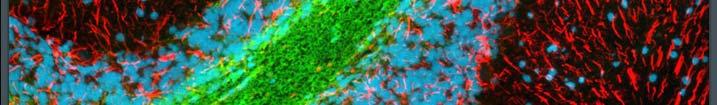
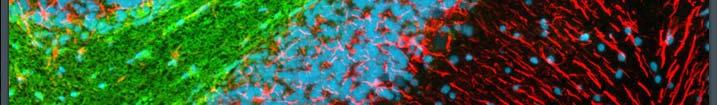
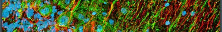
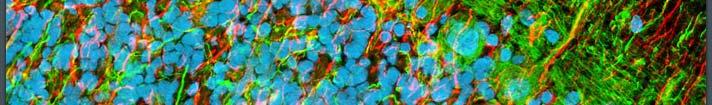
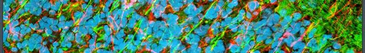
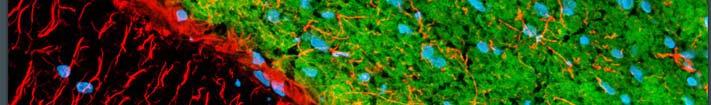
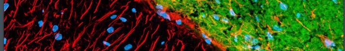
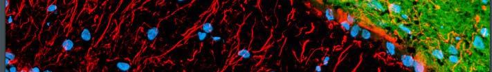
55 2. Tissue slice imaging

56
57


58

59
60


61

62

63


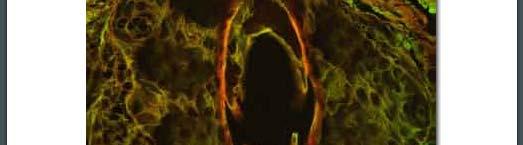


64 Confocal fluorescence
Principles of Light Microscopy
 Monday 8 August 2011 Principles of Light Microscopy 09:00 09:30 Introduction 09:30 10:15 The story of the microscope / 10:15 Coffee 10:30 12:45 Limitations of the eye. Resolution, contrast, magnification.
NDD FLIM Systems for Leica SP2 MP and SP5 MP Multiphoton Microscopes
 NDD FLIM Systems for Leica SP2 MP and SP5 MP Multiphoton Microscopes bh FLIM systems for the confocal and the multiphoton versions of the Leica SP2 and SP5 microscopes are available since 2002 [4]. These
CFIM MICROSCOPY COURSE TIMETABLE PRINCIPLES OF MICROSCOPY MONDAY 6 TH OF JANUARY 2014 FRIDAY 10 TH OF JANUARY 2014
 MICROSCOPY COURSE TIMETABLE PRINCIPLES OF MICROSCOPY MONDAY 6 TH OF JANUARY 2014 FRIDAY 10 TH OF JANUARY 2014 CONFOCAL AND FLUORESCENCE MICROSCOPY MONDAY 20 TH OF JANUARY 2014 FRIDAY 24 TH OF JANUARY 2014
Lens Design I. Lecture 11: Imaging Herbert Gross. Summer term
 Lens Design I Lecture 11: Imaging 2015-06-29 Herbert Gross Summer term 2015 www.iap.uni-jena.de 2 Preliminary Schedule 1 13.04. Basics 2 20.04. Properties of optical systrems I 3 27.05. 4 04.05. Properties
Introductory Guide to Light Microscopy - Biomedical Confocal Microscopy
 Introductory Guide to Light Microscopy - Biomedical Confocal Microscopy 7 May 2007 Michael Hooker Microscopy Facility Michael Chua microscopy@unc.edu 843-3268 6007 Thurston Bowles Wendy Salmon wendy_salmon@med.unc.edu
Samples Carolina sample slides (pollen, algae, ). Clean off oil with lens paper then OpticPad around lens (metal not glass) when done.
. Clean off oil with lens paper then OpticPad around lens (metal not glass) when done.") Bi/BE 227 Winter 2018 Assignment #1 Widefield and confocal laser scanning microscopy Schedule: Jan 3: Lecture Jan 3-12: Students get trained on how to use scopes, start on assignment Jan 3-17: Carrying
Bi/BE 227 Winter 2018 Assignment #1 Widefield and confocal laser scanning microscopy Schedule: Jan 3: Lecture Jan 3-12: Students get trained on how to use scopes, start on assignment Jan 3-17: Carrying
Optical Sectioning. Bo Huang. Pharmaceutical Chemistry
 Optical Sectioning Bo Huang Pharmaceutical Chemistry Approaches to 3D imaging Physical cutting Technical difficulty Highest resolution Highest sensitivity Optical sectioning Simple sample prep. No physical
Microscopy. Marc McGuigan North Quincy High School Thursday, May 11, 2006
 Microscopy Marc McGuigan North Quincy High School Thursday, May 11, 006 Outline Activity Introduction Electromagnetic Spectrum Visible Light Light Microscope AFM Scanning Electron Microscopy Near-Field
Coherent Gradient Sensing Microscopy: Microinterferometric Technique. for Quantitative Cell Detection
 Coherent Gradient Sensing Microscopy: Microinterferometric Technique for Quantitative Cell Detection Proceedings of the SEM Annual Conference June 7-10, 010 Indianapolis, Indiana USA 010 Society for Experimental
Non-Descanned FLIM Systems for Olympus FV-1000 and FV-300 Multiphoton Microscopes
 Non-Descanned FLIM Systems for Olympus FV-1000 and FV-300 Multiphoton Microscopes Abstract. Recently multiphoton versions of the Olympus FV 1000 and FV 300 laser scanning microscopes have become available.
Chapter 3 Geometrical Optics
 Chapter 3 Geometrical Optics Gabriel Popescu University of Illinois at Urbana Champaign Beckman Institute Quantitative Light Imaging Laboratory http://light.ece.uiuc.edu Principles of Optical Imaging Electrical
QUANTITATIVE PHASE IMAGING OF BIOLOGICAL CELLS USING OFF-AXIS METHOD OF WIDE FIELD DIGITAL INTERFERENCE MICROSCOPY (WFDIM)
") http:// QUANTITATIVE PHASE IMAGING OF BIOLOGICAL CELLS USING OFF-AXIS METHOD OF WIDE FIELD DIGITAL INTERFERENCE MICROSCOPY (WFDIM) Pradeep Kumar Behera 1, Dalip Singh Mehta 2 1,2 Physics,Indian Institute
http:// QUANTITATIVE PHASE IMAGING OF BIOLOGICAL CELLS USING OFF-AXIS METHOD OF WIDE FIELD DIGITAL INTERFERENCE MICROSCOPY (WFDIM) Pradeep Kumar Behera 1, Dalip Singh Mehta 2 1,2 Physics,Indian Institute
Last class. This class. Single molecule imaging Deconvolution. FLIM Confocal
 FLIM, Confocal Last class Single molecule imaging Deconvolution This class FLIM Confocal FLIM Fluorescence Lifetime IMaging FLIM Fluorescence lifetime imaging Easier and more accurate quantitation Much
UNIT VI OPTICS ALL THE POSSIBLE FORMULAE
 58 UNIT VI OPTICS ALL THE POSSIBLE FORMULAE Relation between focal length and radius of curvature of a mirror/lens, f = R/2 Mirror formula: Magnification produced by a mirror: m = - = - Snell s law: 1
E x Direction of Propagation. y B y
 x E x Direction of Propagation k z z y B y An electromagnetic wave is a travelling wave which has time varying electric and magnetic fields which are perpendicular to each other and the direction of propagation,
Nonlinear optics and two photon microscopy. Table of contents. Sam Whiteley and Seth Parker PHYS 173/BGGN 266 July 13, 2014
 Nonlinear optics and two photon microscopy Sam Whiteley and Seth Parker PHYS 173/BGGN 266 July 13, 2014 Table of contents 1. Introduction 2. Optical setup 3. Initial images and troubleshooting 4. Determining
Real-time quantitative differential interference contrast (DIC) microscopy implemented via novel liquid crystal prisms
 microscopy implemented via novel liquid crystal prisms") Real-time quantitative differential interference contrast (DIC) microscopy implemented via novel liquid crystal prisms Ramzi N. Zahreddine a, Robert H. Cormack a, Hugh Masterson b, Sharon V. King b, Carol
Real-time quantitative differential interference contrast (DIC) microscopy implemented via novel liquid crystal prisms Ramzi N. Zahreddine a, Robert H. Cormack a, Hugh Masterson b, Sharon V. King b, Carol
LIFA KEY FEATURES APPLICATIONS. Fluorescence Lifetime Attachment LIFA 15001A02 16/03/2015
 LIFA Fluorescence Lifetime Attachment LIFA 151A2 16/3/215 The LIFA is a dedicated system for Fluorescence Lifetime Imaging Microscopy (FLIM). It allows the generation of lifetime images on any widefield
specular diffuse reflection.
 Lesson 8 Light and Optics The Nature of Light Properties of Light: Reflection Refraction Interference Diffraction Polarization Dispersion and Prisms Total Internal Reflection Huygens s Principle The Nature
PH880 Topics in Physics
 PH880 Topics in Physics Modern Optical Imaging (Fall 2010) Overview of week 8 Monday Nonlinear Microscopy Wednesday No class (Mid term week) Quantum Optics Electro- magnetic Optics Wave Optics Ray Optics
Independent Resolution Test of
 Independent Resolution Test of as conducted and published by Dr. Adam Puche, PhD University of Maryland June 2005 as presented by (formerly Thales Optem Inc.) www.qioptiqimaging.com Independent Resolution
12/7/2012. Biomolecular structure. Diffraction, X-ray crystallography, light- and electron microscopy. CD spectroscopy, mass spectrometry
 phase difference at a given distance constructive/destructive interference Biomolecular structure. Diffraction, X-ray crystallography, light- and electron microscopy. CD spectroscopy, mass spectrometry
Confocal Raman Imaging with WITec Sensitivity - Resolution - Speed. Always - Provable - Routinely
 Confocal Raman Imaging with WITec Sensitivity - Resolution - Speed Always - Provable - Routinely WITec GmbH, Ulm, Germany, info@witec.de, www.witec.de A modular microscope series An Example: FLIM optical
Confocal vs. Deconvolution
 Confocal vs. Deconvolution Cesare Covino ALEMBIC Advanced Light and Electron Bio-Imaging Center Istituto Scientifico San Raffaele (Milano) www.hsr.it/research/alembic Fluorescence high contrast high sensibility
Models of Light The wave model: The ray model: The photon model:
 Models of Light The wave model: under many circumstances, light exhibits the same behavior as sound or water waves. The study of light as a wave is called wave optics. The ray model: The properties of
Optical Ptychography Imaging
 Optical Ptychography Imaging Summer Project Annafee Azad Supervisors: Dr Fucai Zhang Prof Ian Robinson Summer 2014 23 October 2014 Optical Ptychography Imaging P a g e 2 Abstract This report details a
Introduction to Inverse Problems
 Introduction to Inverse Problems What is an image? Attributes and Representations Forward vs Inverse Optical Imaging as Inverse Problem Incoherent and Coherent limits Dimensional mismatch: continuous vs
45 µm polystyrene bead embedded in scattering tissue phantom. (a,b) raw images under oblique
 raw images under oblique") Phase gradient microscopy in thick tissue with oblique back-illumination Tim N Ford, Kengyeh K Chu & Jerome Mertz Supplementary Figure 1: Comparison of added versus subtracted raw OBM images 45 µm polystyrene
Phase gradient microscopy in thick tissue with oblique back-illumination Tim N Ford, Kengyeh K Chu & Jerome Mertz Supplementary Figure 1: Comparison of added versus subtracted raw OBM images 45 µm polystyrene
Chuang, Chin-Jung (2011) Proximity projection grating structured illumination microscopy. PhD thesis, University of Nottingham.
 Proximity projection grating structured illumination microscopy. PhD thesis, University of Nottingham.") Chuang, Chin-Jung (2011) Proximity projection grating structured illumination microscopy. PhD thesis, University of Nottingham. Access from the University of Nottingham repository: http://eprints.nottingham.ac.uk/12262/1/pgsim_chinjung_chuang.pdf
Chuang, Chin-Jung (2011) Proximity projection grating structured illumination microscopy. PhD thesis, University of Nottingham. Access from the University of Nottingham repository: http://eprints.nottingham.ac.uk/12262/1/pgsim_chinjung_chuang.pdf
Chapter 36. Image Formation
 Chapter 36 Image Formation Apr 22, 2012 Light from distant things We learn about a distant thing from the light it generates or redirects. The lenses in our eyes create images of objects our brains can
Ray Optics I. Last time, finished EM theory Looked at complex boundary problems TIR: Snell s law complex Metal mirrors: index complex
 Phys 531 Lecture 8 20 September 2005 Ray Optics I Last time, finished EM theory Looked at complex boundary problems TIR: Snell s law complex Metal mirrors: index complex Today shift gears, start applying
Super-Resolved Spatial Light Interference Microscopy
 BOSTON UNIVERSITY Department of Electrical and Computer Engineering RPC Report Super-Resolved Spatial Light Interference Microscopy by OGUZHAN AVCI B.S., Bilkent University, 2012 Submitted in partial fulfillment
INFINITY-CORRECTED TUBE LENSES
 INFINITY-CORRECTED TUBE LENSES For use with Infinity-Corrected Objectives Available in Focal Lengths Used by Thorlabs, Nikon, Leica, Olympus, and Zeiss Designs for Widefield and Laser Scanning Applications
Chapter 35 &36 Physical Optics
 Chapter 35 &36 Physical Optics Physical Optics Phase Difference & Coherence Thin Film Interference 2-Slit Interference Single Slit Interference Diffraction Patterns Diffraction Grating Diffraction & Resolution
EPFL SV PTBIOP BIOP COURSE 2015 OPTICAL SLICING METHODS
 BIOP COURSE 2015 OPTICAL SLICING METHODS OPTICAL SLICING METHODS Scanning Methods Wide field Methods Point Scanning Deconvolution Line Scanning Multiple Beam Scanning Single Photon Multiple Photon Total
Supplementary Information
 Supplementary Information Interferometric scattering microscopy with polarization-selective dual detection scheme: Capturing the orientational information of anisotropic nanometric objects Il-Buem Lee
Formulas of possible interest
 Name: PHYS 3410/6750: Modern Optics Final Exam Thursday 15 December 2011 Prof. Bolton No books, calculators, notes, etc. Formulas of possible interest I = ɛ 0 c E 2 T = 1 2 ɛ 0cE 2 0 E γ = hν γ n = c/v
DSU Start-Up instructions
 DSU Start-Up instructions Always: - start with the 10x objective - properly center the stage around the current objective before changing to another objective - when done, leave the 10x objective in standby
Optics Vac Work MT 2008
 Optics Vac Work MT 2008 1. Explain what is meant by the Fraunhofer condition for diffraction. [4] An aperture lies in the plane z = 0 and has amplitude transmission function T(y) independent of x. It is
Chapter 24. Wave Optics. Wave Optics. The wave nature of light is needed to explain various phenomena
 Chapter 24 Wave Optics Wave Optics The wave nature of light is needed to explain various phenomena Interference Diffraction Polarization The particle nature of light was the basis for ray (geometric) optics
To determine the wavelength of laser light using single slit diffraction
 9 To determine the wavelength of laser light using single slit diffraction pattern 91 Apparatus: Helium-Neon laser or diode laser, a single slit with adjustable aperture width, optical detector and power
Diffraction Diffraction occurs when light waves is passed by an aperture/edge Huygen's Principal: each point on wavefront acts as source of another
 Diffraction Diffraction occurs when light waves is passed by an aperture/edge Huygen's Principal: each point on wavefront acts as source of another circular wave Consider light from point source at infinity
Mag.x system 125 A new high end modular microscope. Dr. Ralf Großkloß QIOPTIQ
 Mag.x system 125 A new high end modular microscope Dr. Ralf Großkloß QIOPTIQ Mag.x system 125 A new high end modular microscope Dr. Ralf Großkloß QIOPTIQ Resolution Speed Sensitivity Qioptiq 2011 3 Optical
Chapter 24. Wave Optics. Wave Optics. The wave nature of light is needed to explain various phenomena
 Chapter 24 Wave Optics Wave Optics The wave nature of light is needed to explain various phenomena Interference Diffraction Polarization The particle nature of light was the basis for ray (geometric) optics
Renishaw invia Raman Microscope (April 2006)
") Renishaw invia Raman Microscope (April 2006) I. Starting the System 1. The main system unit is ON all the time. 2. Switch on the Leica microscope and light source for reflective bright field (BF) imaging.
Renishaw invia Raman Microscope (April 2006) I. Starting the System 1. The main system unit is ON all the time. 2. Switch on the Leica microscope and light source for reflective bright field (BF) imaging.
Lecture PowerPoints. Chapter 24 Physics: Principles with Applications, 7 th edition Giancoli
 Lecture PowerPoints Chapter 24 Physics: Principles with Applications, 7 th edition Giancoli This work is protected by United States copyright laws and is provided solely for the use of instructors in teaching
Spectrographs. C. A. Griffith, Class Notes, PTYS 521, 2016 Not for distribution.
 Spectrographs C A Griffith, Class Notes, PTYS 521, 2016 Not for distribution 1 Spectrographs and their characteristics A spectrograph is an instrument that disperses light into a frequency spectrum, which
Phy 133 Section 1: f. Geometric Optics: Assume the rays follow straight lines. (No diffraction). v 1 λ 1. = v 2. λ 2. = c λ 2. c λ 1.
. v 1 λ 1. = v 2. λ 2. = c λ 2. c λ 1.") Phy 133 Section 1: f Geometric Optics: Assume the rays follow straight lines. (No diffraction). Law of Reflection: θ 1 = θ 1 ' (angle of incidence = angle of reflection) Refraction = bending of a wave
Phy 133 Section 1: f Geometric Optics: Assume the rays follow straight lines. (No diffraction). Law of Reflection: θ 1 = θ 1 ' (angle of incidence = angle of reflection) Refraction = bending of a wave
Bioimage Informatics
 Bioimage Informatics Lecture 10, Spring 2012 Bioimage Data Analysis (II): Applications of Point Feature Detection Techniques: Super Resolution Fluorescence Microscopy Bioimage Data Analysis (III): Edge
To see how a sharp edge or an aperture affect light. To analyze single-slit diffraction and calculate the intensity of the light
 Diffraction Goals for lecture To see how a sharp edge or an aperture affect light To analyze single-slit diffraction and calculate the intensity of the light To investigate the effect on light of many
Lecture 4 Recap of PHYS110-1 lecture Physical Optics - 4 lectures EM spectrum and colour Light sources Interference and diffraction Polarization
 Lecture 4 Recap of PHYS110-1 lecture Physical Optics - 4 lectures EM spectrum and colour Light sources Interference and diffraction Polarization Lens Aberrations - 3 lectures Spherical aberrations Coma,
3. Image formation, Fourier analysis and CTF theory. Paula da Fonseca
 3. Image formation, Fourier analysis and CTF theory Paula da Fonseca EM course 2017 - Agenda - Overview of: Introduction to Fourier analysis o o o o Sine waves Fourier transform (simple examples of 1D
Optics Final Exam Name
 Instructions: Place your name on all of the pages. Do all of your work in this booklet. Do not tear off any sheets. Show all of your steps in the problems for full credit. Be clear and neat in your work.
Chapter 2: Wave Optics
 Chapter : Wave Optics P-1. We can write a plane wave with the z axis taken in the direction of the wave vector k as u(,) r t Acos tkzarg( A) As c /, T 1/ and k / we can rewrite the plane wave as t z u(,)
mag.x system 125 High Resolution Wide Field Micro-Inspection System
 mag.x system 125 High Resolution Wide Field Micro-Inspection System High Resolution Micro-Inspection System Modular System 02 High resolution inspection is being used in many applications. Each application
Lecture 16 Diffraction Ch. 36
 Lecture 16 Diffraction Ch. 36 Topics Newtons Rings Diffraction and the wave theory Single slit diffraction Intensity of single slit diffraction Double slit diffraction Diffraction grating Dispersion and
Supporting Information for Azimuthal Polarization Filtering for Accurate, Precise, and Robust Single-Molecule Localization Microscopy
 Nano Letters Supporting Information for Azimuthal Polarization Filtering for Accurate, Precise, and Robust Single-Molecule Localization Microscopy Matthew D. Lew, and W. E. Moerner *, Departments of Chemistry
DIFFRACTION 4.1 DIFFRACTION Difference between Interference and Diffraction Classification Of Diffraction Phenomena
 4.1 DIFFRACTION Suppose a light wave incident on a slit AB of sufficient width b, as shown in Figure 1. According to concept of rectilinear propagation of light the region A B on the screen should be uniformly
LIFA. SPECIFICATIONs. Fluorescence Lifetime Attachment LIFA14001A02 25/02/2014
 LIFA Fluorescence Lifetime Attachment The LIFA is a dedicated system for Fluorescence Lifetime Imaging Microscopy (FLIM). It allows the generation of lifetime images on any widefield fluorescence microscope
MonoVista CRS+ Raman Microscopes
 MonoVista CRS+ Benefits Deep UV to NIR wavelength range Up to 4 integrated multi-line lasers plus port for large external lasers Dual beam path for UV and VIS/NIR Motorized Laser selection Auto Alignment
UNIT 102-9: INTERFERENCE AND DIFFRACTION
 Name St.No. - Date(YY/MM/DD) / / Section Group # UNIT 102-9: INTERFERENCE AND DIFFRACTION Patterns created by interference of light in a thin film. OBJECTIVES 1. Understand the creation of double-slit
Downloaded from UNIT 06 Optics
 1 Mark UNIT 06 Optics Q1: A partially plane polarised beam of light is passed through a polaroid. Show graphically the variation of the transmitted light intensity with angle of rotation of the Polaroid.
MultiView 2000 TM. The First Tip and Sample Scanning Probe Microscope. The Next Evolution in SPM. The Next Evolution in SPM
 MultiView 2000 TM The First Tip and Sample Scanning Probe Microscope MultiView 2000 TM Using Two Award Winning Nanonics 3D FlatScan Stages MultiView 2000TM Top-View (Top) and open position (Bottom). The
AP* Optics Free Response Questions
 AP* Optics Free Response Questions 1978 Q5 MIRRORS An object 6 centimeters high is placed 30 centimeters from a concave mirror of focal length 10 centimeters as shown above. (a) On the diagram above, locate
Control of Light. Emmett Ientilucci Digital Imaging and Remote Sensing Laboratory Chester F. Carlson Center for Imaging Science 8 May 2007
 Control of Light Emmett Ientilucci Digital Imaging and Remote Sensing Laboratory Chester F. Carlson Center for Imaging Science 8 May 007 Spectro-radiometry Spectral Considerations Chromatic dispersion
HOLOEYE Photonics. HOLOEYE Photonics AG. HOLOEYE Corporation
 HOLOEYE Photonics Products and services in the field of diffractive micro-optics Spatial Light Modulator (SLM) for the industrial research R&D in the field of diffractive optics Micro-display technologies
Indiana Center for Biological Microscopy. BioRad MRC 1024 MP Confocal & Multi-Photon Microscope
 Indiana Center for Biological Microscopy BioRad MRC 1024 MP Confocal & Multi-Photon Microscope Microscope and the Attached Accessories A: B: C: D: E: F: G: H: Mercury Lamp Transmission Light Kr/Ar Laser
Diffraction Diffraction occurs when light waves pass through an aperture Huygen's Principal: each point on wavefront acts as source of another wave
 Diffraction Diffraction occurs when light waves pass through an aperture Huygen's Principal: each point on wavefront acts as source of another wave If light coming from infinity point source at infinity
FLUOVIEW FV1000/FV1200
 FLUOVIEW FV1000/FV1200 UPGRADE TO 3D NANOIMAGING AND SINGLE MOLECULE TRACKING FOR OLYMPUS FLUOVIEW FV1000/FV1200 Within the past few years, several methods have been devised in order to obtain images with
Supplementary Figure 1 Optimum transmissive mask design for shaping an incident light to a desired
 Supplementary Figure 1 Optimum transmissive mask design for shaping an incident light to a desired tangential form. (a) The light from the sources and scatterers in the half space (1) passes through the
Fig The light rays that exit the prism enter longitudinally into an astronomical telescope adjusted for infinite distance.
 Romanian Master of Physics 07 Problem I Reflection and refraction of light A. An interesting prism The main section of a glass prism, situated in air n '.00, has the form of a rhomb with. A thin yellow
Phase contrast microscopy
 Phase contrast microscopy CJR Sheppard Division of Bioengineering National University of Singapore 9 Engineering Drive 1 Singapore 117576 Synopsis Many biological specimens behave as phase objects, that
3. Scanning BRILLOUIN microscopy
 3. Scanning BRILLOUIN microscopy 3.1. Principles of scanning BRILLOUIN microscopy versus ultrasonic pulse-echo techniques Acoustic microscopy spatially resolves the variation of acoustic properties of
Ray Optics. Lecture 23. Chapter 23. Physics II. Course website:
 Lecture 23 Chapter 23 Physics II Ray Optics Course website: http://faculty.uml.edu/andriy_danylov/teaching/physicsii Let s finish talking about a diffraction grating Diffraction Grating Let s improve (more
PH880 Topics in Physics
 PH880 Topics in Physics Modern Optical Imaging (Fall 2010) Overview of week 4 Monday PSF, OTF Bright field microscopy Resolution/NA Deconvolution Wednesday : holiday Impulse response (PSF) in imaging system
Olympus BX51 on Aura. Introduction to the NRI-MCDB Microscopy Facility BX51 Upright Microscope
 Olympus BX51 on Aura Introduction to the NRI-MCDB Microscopy Facility BX51 Upright Microscope Contents Start-up Preparing for Imaging Part I General Part II Transmitted Brightfield Part III Transmitted
Chapter 36. Diffraction. Copyright 2014 John Wiley & Sons, Inc. All rights reserved.
 Chapter 36 Diffraction Copyright 36-1 Single-Slit Diffraction Learning Objectives 36.01 Describe the diffraction of light waves by a narrow opening and an edge, and also describe the resulting interference
Second Year Optics 2017 Problem Set 1
 Second Year Optics 2017 Problem Set 1 Q1 (Revision of first year material): Two long slits of negligible width, separated by a distance d are illuminated by monochromatic light of wavelength λ from a point
Confocal Raman Microscope RAMOS
 Confocal Raman Microscope RAMOS 1 future`s Confocal Raman Microscope RAMOS 2 Confocal Raman Microscope RAMOS Ostec Corporate Group produces and offers hi-tech innovative scientific and analytical equipment.
2, the coefficient of variation R 2, and properties of the photon counts traces
 Supplementary Figure 1 Quality control of FCS traces. (a) Typical trace that passes the quality control (QC) according to the parameters shown in f. The QC is based on thresholds applied to fitting parameters
Laboratory 11: Interference of Light Prelab
 Phys 132L Fall 2018 Laboratory 11: Interference of Light Prelab 1 Diffraction grating Light with wavelength 560 nm is incident on a diffraction grating with slit spacing 2.0 10 6 m. Determinetheangles
Cell-based FLIM Energy-Transfer Measurements Using Alba
 Cell-based FLIM Energy-Transfer Measurements Using Alba ISS, Inc. Introduction This application note describes the use of Alba - Confocal Spectroscopy and Imaging Workstation for the acquisition and analysis
9. Polarizers. Index of. Coefficient of Material Wavelength ( ) Brewster angle refraction (n)
 Brewster angle refraction (n)") 9. Polarizers All polarized light is to some degree elliptical in nature. Basic states of polarization like linear and circular are actually special cases of elliptically polarized light which is defined
9. Polarizers All polarized light is to some degree elliptical in nature. Basic states of polarization like linear and circular are actually special cases of elliptically polarized light which is defined
OPTICS MIRRORS AND LENSES
 Downloaded from OPTICS MIRRORS AND LENSES 1. An object AB is kept in front of a concave mirror as shown in the figure. (i)complete the ray diagram showing the image formation of the object. (ii) How will
Physics 309 Lab 3. where the small angle approximation has been used. This pattern has maxima at. Y Max. n L /d (2)
") Physics 309 Lab 3 Introduction This will be a lab whose purpose is to give you some hands-on experience with optical interference and diffraction, using small green diode lasers as the light sources. Each
Physics 309 Lab 3 Introduction This will be a lab whose purpose is to give you some hands-on experience with optical interference and diffraction, using small green diode lasers as the light sources. Each
Diffraction. Single-slit diffraction. Diffraction by a circular aperture. Chapter 38. In the forward direction, the intensity is maximal.
 Diffraction Chapter 38 Huygens construction may be used to find the wave observed on the downstream side of an aperture of any shape. Diffraction The interference pattern encodes the shape as a Fourier
Progress of the Thomson Scattering Experiment on HSX
 Progress of the Thomson Scattering Experiment on HSX K. Zhai, F.S.B. Anderson, D.T. Anderson HSX Plasma Laboratory, UW-Madison Bill Mason PSL, UW-Madison, The Thomson scattering system being constructed
Digitalna Holografija i Primjene
 Digitalna Holografija i Primjene Hrvoje Skenderović Institut za fiziku 5. PIF Radionica, IRB, 16.12.2014. Holography Dennis Gabor invented holography in 1948 as a method for recording and reconstructing
Unit I Light and Optics
 Unit I Light and Optics Outline By the time you finish this, you should understand the following aspects of our experiment: 1) Why you produce a grating pattern when you cross two laser beams. 2) What
Conversion of evanescent waves into propagating waves by vibrating knife edge
 1 Conversion of evanescent waves into propagating waves by vibrating knife edge S. Samson, A. Korpel and H.S. Snyder Department of Electrical and Computer Engineering, 44 Engineering Bldg., The University
Illumination for the microscope
 Illumination for the microscope Köhler illumination: is a Method of specimen illumination used for transmitted and reflected light. Purpose of Koehler Illumination 1. To obtain even specimen illumination
PHYS2002 Spring 2012 Practice Exam 3 (Chs. 25, 26, 27) Constants
 Constants") PHYS00 Spring 01 Practice Exam 3 (Chs. 5, 6, 7) Constants m m q q p e ε = 8.85 o o p e = 1.67 = 9.11 7 9 7 31 = + 1.60 = 1.60 μ = 4π k = 8.99 g = 9.8 m/s 1 kg 19 19 C kg T m/a N m C / N m C / C 1. A convex
PHYS00 Spring 01 Practice Exam 3 (Chs. 5, 6, 7) Constants m m q q p e ε = 8.85 o o p e = 1.67 = 9.11 7 9 7 31 = + 1.60 = 1.60 μ = 4π k = 8.99 g = 9.8 m/s 1 kg 19 19 C kg T m/a N m C / N m C / C 1. A convex
2011 Optical Science & Engineering PhD Qualifying Examination Optical Sciences Track: Advanced Optics Time allowed: 90 minutes
 2011 Optical Science & Engineering PhD Qualifying Examination Optical Sciences Track: Advanced Optics Time allowed: 90 minutes Answer all four questions. All questions count equally. 3(a) A linearly polarized
Aberrations in Holography
 Aberrations in Holography D Padiyar, J Padiyar 1070 Commerce St suite A, San Marcos, CA 92078 dinesh@triple-take.com joy@triple-take.com Abstract. The Seidel aberrations are described as they apply to
Physical Optics. You can observe a lot just by watching. Yogi Berra ( )
") Physical Optics You can observe a lot just by watching. Yogi Berra (1925-2015) OBJECTIVES To observe some interference and diffraction phenomena with visible light. THEORY In a previous experiment you
Physical Optics You can observe a lot just by watching. Yogi Berra (1925-2015) OBJECTIVES To observe some interference and diffraction phenomena with visible light. THEORY In a previous experiment you
LECTURE 37: Ray model of light and Snell's law
 Lectures Page 1 Select LEARNING OBJECTIVES: LECTURE 37: Ray model of light and Snell's law Understand when the ray model of light is applicable. Be able to apply Snell's Law of Refraction to any system.
Fourier, Fresnel and Image CGHs of three-dimensional objects observed from many different projections
 Fourier, Fresnel and Image CGHs of three-dimensional objects observed from many different projections David Abookasis and Joseph Rosen Ben-Gurion University of the Negev Department of Electrical and Computer
Thin Lenses 4/16/2018 1
 Thin Lenses f 4/16/2018 1 Thin Lenses: Converging Lens C 2 F 1 F 2 C 1 r 2 f r 1 Parallel rays refract twice Converge at F 2 a distance f from center of lens F 2 is a real focal pt because rays pass through
TissueFAXS SL Confocal high throughput configuration (actual appearance of the product may differ)
") TISSUEFAXS CONFOCAL TissueFAXS SL Confocal high throughput configuration (actual appearance of the product may differ) TissueFAXS Confocal provides a unique combination of digital slide scanning and laser
TISSUEFAXS CONFOCAL TissueFAXS SL Confocal high throughput configuration (actual appearance of the product may differ) TissueFAXS Confocal provides a unique combination of digital slide scanning and laser
Basic optics. Geometrical optics and images Interference Diffraction Diffraction integral. we use simple models that say a lot! more rigorous approach
 Basic optics Geometrical optics and images Interference Diffraction Diffraction integral we use simple models that say a lot! more rigorous approach Basic optics Geometrical optics and images Interference