Benefiting from Polarization: Effects at High-NA Imaging
|
|
|
- Clinton Woods
- 5 years ago
- Views:
Transcription
1 Benefiting from Polarization: Effects at High-NA Imaging Bruce W. Smith L. Zavyalova, A. Estroff, Y. Fan, A. Bourov Rochester Institute of Technology P. Zimmerman International SEMACH and Intel J. Cashmore Exitech
2 Polarization Issues and High-NA Polarization is a concern with high-na Effects increase substantially with the large angles allowed with immersion lithography. Illumination effects 2. Mask feature effects 3. Thin film reflectivity at resist /AR
3 Illumination Effects
4 Oblique Angles from High NA Air n i =., s, or Y-polarized TM, p, or X-polarized Resist n i >. - Polarization effects scale with cosine of angle. - TM state will interfere exactly at normal incidence only. - Image is the sum of and TM. - Aerial image metrics no longer useful.
5 Images in Resist Dipole and Cross Quad Illumination Unpolarized Dipole s c =., s r =.25 Contrast =.42 Unpolarized Cross - Quadrupole s c =., s r =.25 Contrast = nm H-V 5 Bar Target 45nm H-V 5 Bar Target Diffraction Energy in Pupil Prolith/8
6 Images in Resist Polarized Dipole Illumination X-Orient / Y-Polarization Dipole s c =., s r =.25 Contrast =.69 Y-Orient / X-Polarization Dipole s c =., s r =.25 Contrast = nm H-V 5 Bar Target 45nm H-V 5 Bar Target Diffraction Energy in Pupil
7 Images in Resist Polarized Cross Quad Illumination Polarized Cross Quad Dipole s c =., s r =.25 Contrast = nm H-V 5 Bar Target Diffraction Energy in Pupil
8 Unpolarized Annular Dipole s o =., s i =.8 Contrast =.2 Images in Resist Annular Illumination TM polarized (Radial) Annulus 45nm H-V 5 Bar Target Diffraction Energy in Pupil polarized (Azimuthal) Annulus
9 Images in Resist Radial and Azimuthal Annular Azimuthal Polarized Annular Dipole s c =., s r =.25 Contrast =.23 Radial Polarized Annular Dipole s c =., s r =.25 Contrast = nm H-V 5 Bar Target 45nm H-V 5 Bar Target Diffraction Energy in Pupil
10 Images in Resist Polarized Annular vs. C-Quad Azimuthal Polarized Annular Dipole s c =., s r =.25 Contrast =.23 Polarized C-Quad Dipole s c =., s r =.25 Contrast = nm H-V 5 Bar Target 45nm H-V 5 Bar Target Diffraction Energy in Pupil
11 Images in Resist through Focus Radial vs. -Dipole.7.6 Modulation in Resist polarized dipole polarized cross-quad Azimuthal annular Unpolarized annular Defocus (nm) - Annular illumination will be used in dipole mode at low k - polarized cross quadrupole may be superior to annular
12 Implementing Polarization ISMT / Exitech.85NA 57nm Polarization methods: Mirror Mirror Birefringence (Glan-Taylor) Selective absorption (Dichroic) Selective reflection (Wollaston) Illuminator Mask Projection Lens Polarizer Mirror Wafer F2 Laser polarizer plates assembly θ B =57.3 unpolarized input laser beam linearly polarized output beam VUV Brewster Angle Plate Polarizer CaF 2 Brewster angle of 57.3º
13 VUV Polarizer Performance Performance specifications Principal (TM) Transmittance: >96%T Extinction Ratio: ~.3 Transmission: 5.5% Efficiency -T(s)/T(p) Extinction T(s)T(p) Transmission [T(p)+T(s)]/2 pair pairs pairs pairs pairs Transmission pair 2 pairs 3 pairs 4 pairs 5 pairs (s-plane) TM (p-plane) Incidence Angle (degrees)


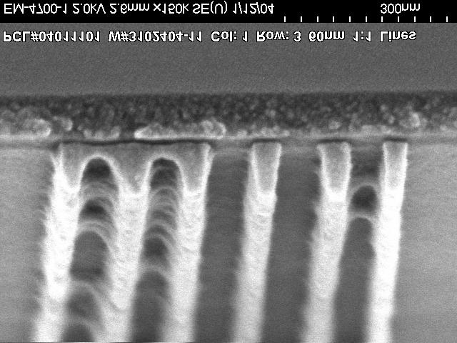
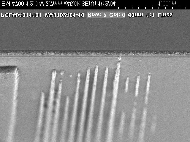
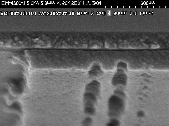
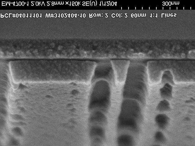
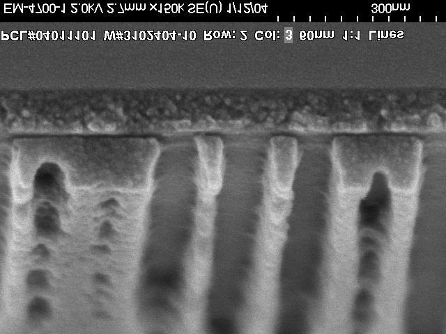
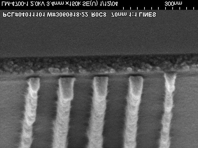
14 Binary 6nm :, Polarized Imaging Focus (positive direction) (.5 µm steps) TM 6nm :, Binary mask DIPOLE illum.77s c/.s p


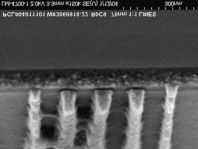
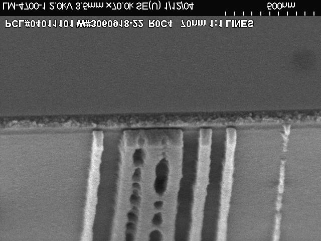
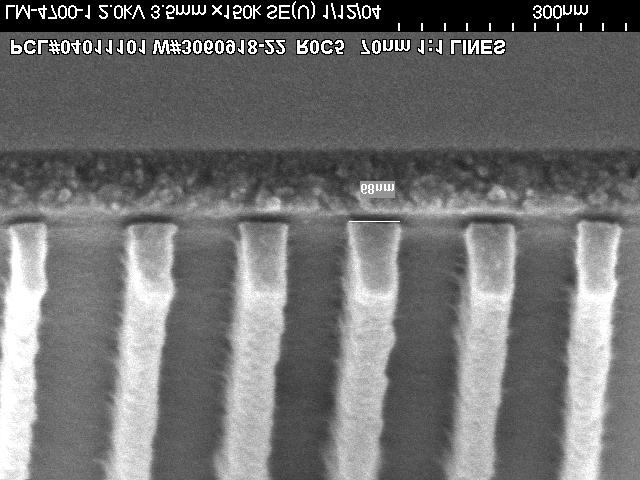
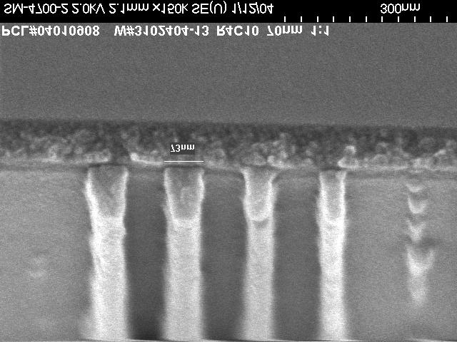
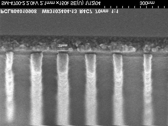
15 AltPSM 7nm :.3σ, Polarized Focus (positive direction) (. µm steps) Focus (positive direction) (.5 µm steps) TM Focus (positive direction) Unpolarized (.5 µm steps)
16 Mask Feature Effects
17 Mask-induced Polarization Wire Grid Polarizers Sub-wavelength Zero-Order Grating Parallel reflected component (TM) Polarizing wires (Wood, Philosophical Magazine, 92). Resonant high orders (Rayleigh, Philosophical Magazine, 97). p l = ( n ± sinq ) k Perpendicular transmitted component ()
18 Mask Polarization Graded Cr x O y N z over Cr x N y 8 atomic % C N O Cr Si Mask induced polarization effects at low k, A. Estroff et al Depth (Angstroms) Cr-O-N Stack Composition Layer Layer 2 Layer 3 Layer 4 Cr 9.% 8.9% 9.45%.% CrN.% 2.%.5%.% CrOx.% 79.% 89.5%.% Data for Cr-O-N Stack (Layer is closest to substrate, Layer 4 is furthest) Layer Layer 2 Layer 3 Layer 4 93nm 248nm 93nm 248nm 93nm 248nm 93nm 248nm n k Thickness (A)
19 Cr-O-N 93nm Binary Mask Polarization Normal incidence RCWA of mask structures Degree of Polarization = (-TM)/(+TM) Mask induced polarization effects at low k, A. Estroff et al Degree of Polarization Degree of Polarization TM 25% 2% 5% % 5% % % % -% -2% -3% -4% -5% -6% Cr-O-N 93nm - First Order st Order Polarization Grating Period (µm) Cr-O-N 93nm - Zero Order Degree of Polarization Unpolarized Transmission Grating Period (µm) Degree of Polarization Unpolarized Transmission th Order Polarization 9% 8% 7% 6% 5% 4% 3% 2% % % 3% 25% 2% 5% % 5% % Transmission Transmission G-Solver
20 93nm Attenuated PSM Polarization Normal incidence TaN-Si3N4 st-order Degree MoO3-SiO2 st-order Degree Degree of Polarization TM 3% 2% % % -% -2% -3% -4% -5% -6% TaN-Si3N4 Unpolarized st-order T MoO3-SiO2 Unpolarized st-order T 2% 5% st Order % 5% % -5% -% Transmission -5% -2% Grating Period (µm) TaN-Si3N4 -Order Degree MoO3-SiO2 -Order Degree TaN-Si3N4 Unpolarized -order T MoO3-SiO2 Unpolarized -order T % Transmitting Attenuated PSM Materials TaN - Si 3 N 4 MoO 3 SiO 2 Mask induced polarization effects at low k, A. Estroff et al Degree of Polarization TM 8% 6% 4% 2% % -2% -4% -6% -8% -% th Order Grating Period (µm) 6% 4% 2% % -2% -4% -6% -8% -% -2% Transmission
21 Asymmetrical Order Polarization Angular incidence.2na 4X Imaging System 7.45 in air,.5 in glass Mask induced polarization effects at low k, A. Estroff et al Degree of Polarization TM Degree of Polarization TM 4% 3% 2% % % -% 4% 3% 2% % % -% +st Order Polarization Degree of Polarization Unpolarized Transmission Grating Period (mm) -st Order Polarization Degree of Polarization Unpolarized Transmission Grating Period (mm) 4% 2% % 8% 6% 4% 2% % 4% 2% % 8% 6% 4% 2% % Transmission Transmission
22 Thin Film Reflection Effects

 =.")
 =.")
 = 2.")
23 ARC Reflectivity at Normal Incidence 93nm in Resist (.7,.5), 2% reflectivity contours n(arc) =.5 ARC thickness (nm) 2 n(arc) =.7 ARC thickness (nm) 2 n(arc) =.9 n(arc) = 2. ARC thickness (nm) 2 ARC thickness (nm) 2

 =.")
 =.")
 = 2.")
24 ARC Reflectivity at 45 Incidence Unpolarized radiation, 2% reflectivity contours n(arc) =.5 ARC thickness (nm) 2 n(arc) =.7 ARC thickness (nm) 2 n(arc) =.9 n(arc) = 2. ARC thickness (nm) 2 ARC thickness (nm) 2

 =.")
 2 9")
 2 ARC")
25 ARC Reflectivity at 45 Incidence Polarization, 2% reflectivity contours n(arc) =.5 ARC thickness (nm) 2 n(arc) =.7 ARC thickness (nm) 2 n(arc) =.9 n(arc) = 2. ARC thickness (nm) 2 ARC thickness (nm) 2
 2 n(arc) =.7 ARC thickness (nm) 2 n(arc) =.9 n(arc) = 2.")
26 ARC Reflectivity at 45 Incidence TM Polarization, 2% reflectivity contours n(arc) =.5 ARC thickness (nm) 2 n(arc) =.7 ARC thickness (nm) 2 n(arc) =.9 n(arc) = 2. ARC thickness (nm) 2 ARC thickness (nm) 2
27 Single Layer ARC Optimization for.2na Reflectance (%) optimized, ARC(.7,.5), 35nm Avg TM Reflectance (%) optimized, ARC(.7,.3), 52nm Avg TM Angle (degrees) Angle (degrees) Reflectance (%) TM optimized, ARC(.7,.5), 52nm Avg TM Reflectance (%) optimized, ARC(.7,.3), 48nm Avg TM Angle (degrees) Angle (degrees) TF Calc
28 ARC for -45 /TM Polarization Multilayer Designs Full angular optimization -45 (.2NA) 25. Reflectance (%) Avg TM ARC Resist (.7,.5) 42nm (.7,.2) 48nm (.7,.5) Poly-Si Angle (degrees) Reflectance (%) Avg TM Angle (degrees) Normal incidence optimized ARC(.7,.5) 35nm
29 Conclusions - polarized illumination can provide resolution enhancement, C-Quad may be useful - Early results at 57nm confirm polarized imaging - Mask induce polarization effects exist, the impact is to be seen (e.g. Mag). - Resist stacks require full angle / polarization optimization
Benefiting from polarization effects on high-na imaging
 Benefiting from polarization effects on high-na imaging Bruce W. Smith, Lena Zavyalova, Andrew Estroff Rochester Institute of Technology, Microelectronic Engineering Department 82 Lomb Memorial Drive,
Challenges in high NA, polarization, and photoresists
 Challenges in high NA, polarization, and photoresists Bruce W. Smith *a, Julian Cashmore **b a Rochester Institute of Technology, Microelectronic Engineering Dept., Rochester, NY b Exitech Limited, Oxford
Study of Air Bubble Induced Light Scattering Effect On Image Quality in 193 nm Immersion Lithography
 Study of Air Bubble Induced Light Scattering Effect On Image Quality in 193 nm Immersion Lithography Y. Fan, N. Lafferty, A. Bourov, L. Zavyalova, B. W. Smith Rochester Institute of Technology Microelectronic
Chapter 24. Wave Optics. Wave Optics. The wave nature of light is needed to explain various phenomena
 Chapter 24 Wave Optics Wave Optics The wave nature of light is needed to explain various phenomena Interference Diffraction Polarization The particle nature of light was the basis for ray (geometric) optics
9. Polarizers. Index of. Coefficient of Material Wavelength ( ) Brewster angle refraction (n)
 Brewster angle refraction (n)") 9. Polarizers All polarized light is to some degree elliptical in nature. Basic states of polarization like linear and circular are actually special cases of elliptically polarized light which is defined
9. Polarizers All polarized light is to some degree elliptical in nature. Basic states of polarization like linear and circular are actually special cases of elliptically polarized light which is defined
Chapter 24. Wave Optics. Wave Optics. The wave nature of light is needed to explain various phenomena
 Chapter 24 Wave Optics Wave Optics The wave nature of light is needed to explain various phenomena Interference Diffraction Polarization The particle nature of light was the basis for ray (geometric) optics
Protocol for Lab. Fundamentals
 Protocol for Lab Fundamentals Content 1. Beam propagation, law of reflection, and Snellius law... 3 1.1. Air-metal and air-plexiglass transition... 3 1.2. Air-water... 3 1.3. Plexiglass-water... 3 1.4.
IB-2 Polarization Practice
 Name: 1. Plane-polarized light is incident normally on a polarizer which is able to rotate in the plane perpendicular to the light as shown below. In diagram 1, the intensity of the incident light is 8
Chapter 82 Example and Supplementary Problems
 Chapter 82 Example and Supplementary Problems Nature of Polarized Light: 1) A partially polarized beam is composed of 2.5W/m 2 of polarized and 4.0W/m 2 of unpolarized light. Determine the degree of polarization
Unit 5.C Physical Optics Essential Fundamentals of Physical Optics
 Unit 5.C Physical Optics Essential Fundamentals of Physical Optics Early Booklet E.C.: + 1 Unit 5.C Hwk. Pts.: / 25 Unit 5.C Lab Pts.: / 20 Late, Incomplete, No Work, No Units Fees? Y / N 1. Light reflects
Basic Optics : Microlithography Optics Part 4: Polarization
 Electromagnetic Radiation Polarization: Linear, Circular, Elliptical Ordinary and extraordinary rays Polarization by reflection: Brewster angle Polarization by Dichroism Double refraction (Birefringence)
37 (15 pts) Apply Snell s law twice (external, then internal) to find it emerges at the same angle.
 Apply Snell s law twice (external, then internal) to find it emerges at the same angle.") 37 (15 pts) Apply Snell s law twice (external, then internal) to find it emerges at the same angle. 38. (4 pts) Review the section on phase changes on reflection in Pedrotti section 3-3 Solution (a) For
37 (15 pts) Apply Snell s law twice (external, then internal) to find it emerges at the same angle. 38. (4 pts) Review the section on phase changes on reflection in Pedrotti section 3-3 Solution (a) For
Immersion Microlithography at 193 nm with a Talbot Prism Interferometer
 RIT Scholar Works Presentations and other scholarship 5-28-2004 Immersion Microlithography at 193 nm with a Talbot Prism Interferometer Anatoly Bourov Yongfa Fan Frank Cropanese Neal Lafferty Lena V. Zavyalova
Three-dimensional imaging of 30-nm nanospheres using immersion interferometric lithography
 Three-dimensional imaging of 30-nm nanospheres using immersion interferometric lithography Jianming Zhou *, Yongfa Fan, Bruce W. Smith Microelectronics Engineering Department, Rochester Institute of Technology,
Compact Multilayer Film Structure for Angle Insensitive. Color Filtering
 1 Compact Multilayer Film Structure for Angle Insensitive Color Filtering Chenying Yang, Weidong Shen*, Yueguang Zhang, Kan Li, Xu Fang, Xing Zhang, and Xu Liu * E-mail: adongszju@hotmail.com
New methodology to characterize printing performance of mask materials by analyzing diffraction efficiency
 9-Oct-7 4th nternational Symposium on mmersion Lithography * The title has been modified [ 865 ; P-HM-5/5 ] New methodology to characterize printing performance of mask materials by analyzing diffraction
Optics Vac Work MT 2008
 Optics Vac Work MT 2008 1. Explain what is meant by the Fraunhofer condition for diffraction. [4] An aperture lies in the plane z = 0 and has amplitude transmission function T(y) independent of x. It is
Physics 214 Midterm Fall 2003 Form A
 1. A ray of light is incident at the center of the flat circular surface of a hemispherical glass object as shown in the figure. The refracted ray A. emerges from the glass bent at an angle θ 2 with respect
1.! Questions about reflected intensity. [Use the formulas on p. 8 of Light.] , no matter
![1.! Questions about reflected intensity. [Use the formulas on p. 8 of Light.] , no matter](/thumbs/81/83191942.jpg "1.! Questions about reflected intensity. [Use the formulas on p. 8 of Light.] , no matter") Reading: Light Key concepts: Huygens s principle; reflection; refraction; reflectivity; total reflection; Brewster angle; polarization by absorption, reflection and Rayleigh scattering. 1.! Questions about
Reading: Light Key concepts: Huygens s principle; reflection; refraction; reflectivity; total reflection; Brewster angle; polarization by absorption, reflection and Rayleigh scattering. 1.! Questions about
Refraction and Polarization of Light
 Chapter 9 Refraction and Polarization of Light Name: Lab Partner: Section: 9.1 Purpose The purpose of this experiment is to demonstrate several consequences of the fact that materials have di erent indexes
Diffraction. Single-slit diffraction. Diffraction by a circular aperture. Chapter 38. In the forward direction, the intensity is maximal.
 Diffraction Chapter 38 Huygens construction may be used to find the wave observed on the downstream side of an aperture of any shape. Diffraction The interference pattern encodes the shape as a Fourier
Chapter 24. Wave Optics
 Chapter 24 Wave Optics Diffraction Huygen s principle requires that the waves spread out after they pass through slits This spreading out of light from its initial line of travel is called diffraction
Chapter 24. Wave Optics
 Chapter 24 Wave Optics Wave Optics The wave nature of light is needed to explain various phenomena Interference Diffraction Polarization The particle nature of light was the basis for ray (geometric) optics
Interference with polarized light
 Interference with polarized light Summary of the previous lecture (see lecture 3 - slides 12 to 25) With polarized light E 1 et E 2 are complex amplitudes: E 1 + E 2 e iϕ 2 = E 1 2 + E 2 2 + 2 Re(E 1 *
ECEG105/ECEU646 Optics for Engineers Course Notes Part 5: Polarization
 ECEG105/ECEU646 Optics for Engineers Course Notes Part 5: Polarization Prof. Charles A. DiMarzio Northeastern University Fall 2008 Sept 2008 11270-05-1 Wave Nature of Light Failure of Raytracing Zero-λ
Chapter 38. Diffraction Patterns and Polarization
 Chapter 38 Diffraction Patterns and Polarization Diffraction Light of wavelength comparable to or larger than the width of a slit spreads out in all forward directions upon passing through the slit This
Snell or Fresnel The influence of material index on hyper NA lithography
 Snell or Fresnel The influence of material index on hyper NA lithography Bruce Smith and Jianming Zhou Rochester Institute of Technology, Center for Nanolithography Research Microelectronic Engineering
normal angle of incidence increases special angle no light is reflected
 Reflection from transparent materials (Chapt. 33 last part) When unpolarized light strikes a transparent surface like glass there is both transmission and reflection, obeying Snell s law and the law of
The Death of the Aerial Image
 Tutor50.doc: Version 5/9/05 T h e L i t h o g r a p h y E x p e r t (August 005) The Death of the Aerial Image Chris A. Mack, KLA-Tencor, FINLE Division, Austin, Texas The aerial image is, quite literally,
Experiment 8 Wave Optics
 Physics 263 Experiment 8 Wave Optics In this laboratory, we will perform two experiments on wave optics. 1 Double Slit Interference In two-slit interference, light falls on an opaque screen with two closely
Diffraction Efficiency
 Diffraction Efficiency Turan Erdogan Gratings are based on diffraction and interference: Diffraction gratings can be understood using the optical principles of diffraction and interference. When light
E x Direction of Propagation. y B y
 x E x Direction of Propagation k z z y B y An electromagnetic wave is a travelling wave which has time varying electric and magnetic fields which are perpendicular to each other and the direction of propagation,
Final Exam. Today s Review of Optics Polarization Reflection and transmission Linear and circular polarization Stokes parameters/jones calculus
 Physics 42200 Waves & Oscillations Lecture 40 Review Spring 206 Semester Matthew Jones Final Exam Date:Tuesday, May 3 th Time:7:00 to 9:00 pm Room: Phys 2 You can bring one double-sided pages of notes/formulas.
Polarizers. Laser Polarizers Broadband Polarizing Beamsplitting Cubes 78 Narrowband Polarizing Beamsplitting Cubes 79
 Prisms Introduction to Right Angle Prisms 72 Quality Right Angle Prisms 73 Laboratory Quality Right Angle Prisms 73 Equilateral Prisms 74 Wedge Prisms 75 Anamorphic Prism Pair 75 Penta Prisms 76 Dove Prisms
Waves & Oscillations
 Physics 42200 Waves & Oscillations Lecture 40 Review Spring 2016 Semester Matthew Jones Final Exam Date:Tuesday, May 3 th Time:7:00 to 9:00 pm Room: Phys 112 You can bring one double-sided pages of notes/formulas.
specular diffuse reflection.
 Lesson 8 Light and Optics The Nature of Light Properties of Light: Reflection Refraction Interference Diffraction Polarization Dispersion and Prisms Total Internal Reflection Huygens s Principle The Nature
Refraction and Polarization of Light
 Chapter 9 Refraction and Polarization of Light Name: Lab Partner: Section: 9.1 Purpose The purpose of this experiment is to demonstrate several consequences of the fact that materials have di erent indexes
2013 International Workshop on EUV Lithography Hanyang University
 Agenda What is photon shot noise? Attenuated PSM Stochastic simulation condition Simulation result Conclusion What is photon shot noise? Attenuated PSM Stochastic simulation condition Simulation result
POLARIZATION COMPONENTS
 POLRIZTION COMPONENTS Mirrors We offer a wide range of cube and plate polarizers to perform under different operating conditions including high energy, broad bandwidths, low dispersion and high extinction.
Approaching the numerical aperture of water - Immersion lithography at 193nm
 Approaching the numerical aperture of water - Immersion lithography at 193nm Bruce W. Smith, Anatoly Bourov, Yongfa Fan, Lena Zavyalova, Neal Lafferty, Frank Cropanese, Rochester Institute of Technology,
Discussion Question 13A P212, Week 13 Electromagnetic Waves
 Discussion Question 13A P1, Week 13 Electromagnetic Waves This problem is a continuation of discussion question 1B from last week. Please refer to your work from last week as necessary. A laser beam travels
Image Degradation due to Phase Effects in Chromeless Phase Lithography
 Image Degradation due to Phase Effects in Chromeless Phase Lithography Karsten Bubke *, Martin Sczyrba, KT Park, Ralf Neubauer, Rainer Pforr 2, Jens Reichelt 2, Ralf Ziebold 2 Advanced Mask Technology
1. Particle Scattering. Cogito ergo sum, i.e. Je pense, donc je suis. - René Descartes
 1. Particle Scattering Cogito ergo sum, i.e. Je pense, donc je suis. - René Descartes Generally gas and particles do not scatter isotropically. The phase function, scattering efficiency, and single scattering
Electromagnetic waves
 Electromagnetic waves Now we re back to thinking of light as specifically being an electromagnetic wave u u u oscillating electric and magnetic fields perpendicular to each other propagating through space
Outline The Refraction of Light Forming Images with a Plane Mirror 26-3 Spherical Mirror 26-4 Ray Tracing and the Mirror Equation
 Chapter 6 Geometrical Optics Outline 6-1 The Reflection of Light 6- Forming Images with a Plane Mirror 6-3 Spherical Mirror 6-4 Ray Tracing and the Mirror Equation 6-5 The Refraction of Light 6-6 Ray Tracing
Waves & Oscillations
 Physics 42200 Waves & Oscillations Lecture 41 Review Spring 2013 Semester Matthew Jones Final Exam Date:Tuesday, April 30 th Time:1:00 to 3:00 pm Room: Phys 112 You can bring two double-sided pages of
Chapter 2: Wave Optics
 Chapter : Wave Optics P-1. We can write a plane wave with the z axis taken in the direction of the wave vector k as u(,) r t Acos tkzarg( A) As c /, T 1/ and k / we can rewrite the plane wave as t z u(,)
Defect Repair for EUVL Mask Blanks
 Defect Repair for EUVL Mask Blanks A.Barty, S.Hau-Riege, P.B.Mirkarimi, D.G.Stearns, H.Chapman, D.Sweeney Lawrence Livermore National Laboratory M.Clift Sandia National Laboratory E.Gullikson, M.Yi Lawrence
Optics Final Exam Name
 Instructions: Place your name on all of the pages. Do all of your work in this booklet. Do not tear off any sheets. Show all of your steps in the problems for full credit. Be clear and neat in your work.
AP* Optics Free Response Questions
 AP* Optics Free Response Questions 1978 Q5 MIRRORS An object 6 centimeters high is placed 30 centimeters from a concave mirror of focal length 10 centimeters as shown above. (a) On the diagram above, locate
Phy 133 Section 1: f. Geometric Optics: Assume the rays follow straight lines. (No diffraction). v 1 λ 1. = v 2. λ 2. = c λ 2. c λ 1.
. v 1 λ 1. = v 2. λ 2. = c λ 2. c λ 1.") Phy 133 Section 1: f Geometric Optics: Assume the rays follow straight lines. (No diffraction). Law of Reflection: θ 1 = θ 1 ' (angle of incidence = angle of reflection) Refraction = bending of a wave
Phy 133 Section 1: f Geometric Optics: Assume the rays follow straight lines. (No diffraction). Law of Reflection: θ 1 = θ 1 ' (angle of incidence = angle of reflection) Refraction = bending of a wave
The sources must be coherent. This means they emit waves with a constant phase with respect to each other.
 CH. 24 Wave Optics The sources must be coherent. This means they emit waves with a constant phase with respect to each other. The waves need to have identical wavelengths. Can t be coherent without this.
The diffraction pattern from a hexagonally-shaped hole. Note the six-fold symmetry of the pattern. Observation of such complex patterns can reveal
 The diffraction pattern from a hexagonally-shaped hole. Note the six-fold symmetry of the pattern. Observation of such complex patterns can reveal the underlying symmetry structure of the object that diffracts
Phase. E = A sin(2p f t+f) (wave in time) or E = A sin(2p x/l +f) (wave in space)
 (wave in time) or E = A sin(2p x/l +f) (wave in space)") Interference When two (or more) waves arrive at a point (in space or time), they interfere, and their amplitudes may add or subtract, depending on their frequency and phase. 1 Phase E = A sin(2p f t+f)
Interference When two (or more) waves arrive at a point (in space or time), they interfere, and their amplitudes may add or subtract, depending on their frequency and phase. 1 Phase E = A sin(2p f t+f)
Understanding and selecting diffraction gratings
 Understanding and selecting diffraction gratings Diffraction gratings are used in a variety of applications where light needs to be spectrally split, including engineering, communications, chemistry, physics
13. Brewster angle measurement
 13. Brewster angle measurement Brewster angle measurement Objective: 1. Verification of Malus law 2. Measurement of reflection coefficient of a glass plate for p- and s- polarizations 3. Determination
Investigation of the foot-exposure impact in hyper-na immersion lithography when using thin anti-reflective coating
 Investigation of the foot-exposure impact in hyper-na immersion lithography when using thin anti-reflective coating Darron Jurajda b, Enrico Tenaglia a, Jonathan Jeauneau b, Danilo De Simone a, Zhimin
INTERFERENCE. where, m = 0, 1, 2,... (1.2) otherwise, if it is half integral multiple of wavelength, the interference would be destructive.
 otherwise, if it is half integral multiple of wavelength, the interference would be destructive.") 1.1 INTERFERENCE When two (or more than two) waves of the same frequency travel almost in the same direction and have a phase difference that remains constant with time, the resultant intensity of light
1.1 INTERFERENCE When two (or more than two) waves of the same frequency travel almost in the same direction and have a phase difference that remains constant with time, the resultant intensity of light
Second Year Optics 2017 Problem Set 1
 Second Year Optics 2017 Problem Set 1 Q1 (Revision of first year material): Two long slits of negligible width, separated by a distance d are illuminated by monochromatic light of wavelength λ from a point
Phys 104: College Physics EXAM 3
 Phys 14: College Physics Key Name I. VERY SHORT ANSWER: EXAM 3 FRIDAY, APRIL 16, 21 1) 3 A cat plays with a butterfly at dawn and looks directly up at light from the sun rising in the east that has been
Reflectivity metrics for optimization of anti-reflection coatings on wafers with topography
 Reflectivity metrics for optimization of anti-reflection coatings on wafers with topography Mark D. Smith, Trey Graves, John Biafore, and Stewart Robertson KLA-Tencor Corp, 8834 N. Capital of Texas Hwy,
Review Session 1. Dr. Flera Rizatdinova
 Review Session 1 Dr. Flera Rizatdinova Summary of Chapter 23 Index of refraction: Angle of reflection equals angle of incidence Plane mirror: image is virtual, upright, and the same size as the object
CHAPTER 26 INTERFERENCE AND DIFFRACTION
 CHAPTER 26 INTERFERENCE AND DIFFRACTION INTERFERENCE CONSTRUCTIVE DESTRUCTIVE YOUNG S EXPERIMENT THIN FILMS NEWTON S RINGS DIFFRACTION SINGLE SLIT MULTIPLE SLITS RESOLVING POWER 1 IN PHASE 180 0 OUT OF
Polarization. Components of Polarization: Malus Law. VS203B Lecture Notes Spring, Topic: Polarization
 VS03B Lecture Notes Spring, 013 011 Topic: Polarization Polarization Recall that I stated that we had to model light as a transverse wave so that we could use the model to explain polarization. The electric
Lecture 17 (Polarization and Scattering) Physics Spring 2018 Douglas Fields
 Physics Spring 2018 Douglas Fields") Lecture 17 (Polarization and Scattering) Physics 262-01 Spring 2018 Douglas Fields Reading Quiz When unpolarized light passes through an ideal polarizer, the intensity of the transmitted light is: A) Unchanged
Lecture 17 (Polarization and Scattering) Physics 262-01 Spring 2018 Douglas Fields Reading Quiz When unpolarized light passes through an ideal polarizer, the intensity of the transmitted light is: A) Unchanged
PHYS2002 Spring 2012 Practice Exam 3 (Chs. 25, 26, 27) Constants
 Constants") PHYS00 Spring 01 Practice Exam 3 (Chs. 5, 6, 7) Constants m m q q p e ε = 8.85 o o p e = 1.67 = 9.11 7 9 7 31 = + 1.60 = 1.60 μ = 4π k = 8.99 g = 9.8 m/s 1 kg 19 19 C kg T m/a N m C / N m C / C 1. A convex
PHYS00 Spring 01 Practice Exam 3 (Chs. 5, 6, 7) Constants m m q q p e ε = 8.85 o o p e = 1.67 = 9.11 7 9 7 31 = + 1.60 = 1.60 μ = 4π k = 8.99 g = 9.8 m/s 1 kg 19 19 C kg T m/a N m C / N m C / C 1. A convex
Dispersion Polarization
 Dispersion Polarization Phys Phys 2435: 22: Chap. 33, 31, Pg 1 Dispersion New Topic Phys 2435: Chap. 33, Pg 2 The Visible Spectrum Remember that white light contains all the colors of the s p e c t r u
Evanescent wave imaging in optical lithography
 Evanescent wave imaging in optical lithography Bruce W. Smith, Yongfa Fan, Jianming Zhou, Neal Lafferty, Andrew Estroff Rochester Institute of Technology, 82 Lomb Memorial Drive, Rochester, New York, 14623
Laboratory 6: Light and the Laser
 Laboratory 6: Light and the Laser WARNING NEVER LOOK DIRECTLY AT LASER LIGHT Index of Refraction: Snell's Law 1. Read the section on physical optics in some introductory physics text. 2. Set the semicircular
Lesson 1 Scattering, Diffraction, and Radiation
 Lesson 1 Scattering, Diffraction, and Radiation Chen-Bin Huang Department of Electrical Engineering Institute of Photonics Technologies National Tsing Hua University, Taiwan Various slides under courtesy
PHYS 3410/6750: Modern Optics Midterm #2
 Name: PHYS 3410/6750: Modern Optics Midterm #2 Wednesday 16 November 2011 Prof. Bolton Only pen or pencil are allowed. No calculators or additional materials. PHYS 3410/6750 Fall 2011 Midterm #2 2 Problem
NEW OPTICAL MEASUREMENT TECHNIQUE FOR SI WAFER SURFACE DEFECTS USING ANNULAR ILLUMINATION WITH CROSSED NICOLS
 NEW OPTICAL MEASUREMENT TECHNIQUE FOR SI WAFER SURFACE DEFECTS USING ANNULAR ILLUMINATION WITH CROSSED NICOLS Satoru Takahashi 1, Takashi Miyoshi 1, Yasuhiro Takaya 1, and Takahiro Abe 2 1 Department of
Supplementary Figure 1 Optimum transmissive mask design for shaping an incident light to a desired
 Supplementary Figure 1 Optimum transmissive mask design for shaping an incident light to a desired tangential form. (a) The light from the sources and scatterers in the half space (1) passes through the
Chapter 8: Physical Optics
 Chapter 8: Physical Optics Whether light is a particle or a wave had puzzled physicists for centuries. In this chapter, we only analyze light as a wave using basic optical concepts such as interference
LIGHT SCATTERING THEORY
 LIGHT SCATTERING THEORY Laser Diffraction (Static Light Scattering) When a Light beam Strikes a Particle Some of the light is: Diffracted Reflected Refracted Absorbed and Reradiated Reflected Refracted
Finding the Optimal Polarizer
 Finding the Optimal Polarizer William S. Barbarow Meadowlark Optics Inc., 5964 Iris Parkway, Frederick, CO 80530 (Dated: January 12, 2009) I have an application requiring polarized light. What type of
Advanced modelling of gratings in VirtualLab software. Site Zhang, development engineer Lignt Trans
 Advanced modelling of gratings in VirtualLab software Site Zhang, development engineer Lignt Trans 1 2 3 4 Content Grating Order Analyzer Rigorous Simulation of Holographic Generated Volume Grating Coupled
d has a relationship with ψ
 Principle of X-Ray Stress Analysis Metallic materials consist of innumerable crystal grains. Each grain usually faces in a random direction. When stress is applied on such materials, the interatomic distance
OPSE FINAL EXAM Fall CLOSED BOOK. Two pages (front/back of both pages) of equations are allowed.
 of equations are allowed.") CLOSED BOOK. Two pages (front/back of both pages) of equations are allowed. YOU MUST SHOW YOUR WORK. ANSWERS THAT ARE NOT JUSTIFIED WILL BE GIVEN ZERO CREDIT. ALL NUMERICAL ANSERS MUST HAVE UNITS INDICATED.
CLOSED BOOK. Two pages (front/back of both pages) of equations are allowed. YOU MUST SHOW YOUR WORK. ANSWERS THAT ARE NOT JUSTIFIED WILL BE GIVEN ZERO CREDIT. ALL NUMERICAL ANSERS MUST HAVE UNITS INDICATED.
Human Retina. Sharp Spot: Fovea Blind Spot: Optic Nerve
 I am Watching YOU!! Human Retina Sharp Spot: Fovea Blind Spot: Optic Nerve Human Vision An optical Tuning Fork Optical Antennae: Rods & Cones Rods: Intensity Cones: Color Where does light actually come
Lecture 26, March 16, Chapter 35, Polarization
 Physics 5B Lecture 26, March 16, 2012 Chapter 35, Polarization Simple Spectrometer d sin m Resolving power, to separate two lines closely spaced in wavelength by : R mn Resolving Power Two lines not resolved.
ratio of the volume under the 2D MTF of a lens to the volume under the 2D MTF of a diffraction limited
 SUPPLEMENTARY FIGURES.9 Strehl ratio (a.u.).5 Singlet Doublet 2 Incident angle (degree) 3 Supplementary Figure. Strehl ratio of the singlet and doublet metasurface lenses. Strehl ratio is the ratio of
1.Rayleigh and Mie scattering. 2.Phase functions. 4.Single and multiple scattering
 5 November 2014 Outline 1.Rayleigh and Mie scattering 2.Phase functions 3.Extinction 4.Single and multiple scattering Luca Lelli luca@iup.physik.uni-bremen.de Room U2080 Phone 0421.218.62097 Scattering
SILICON PHOTONICS WAVEGUIDE AND ITS FIBER INTERCONNECT TECHNOLOGY. Jeong Hwan Song
 SILICON PHOTONICS WAVEGUIDE AND ITS FIBER INTERCONNECT TECHNOLOGY Jeong Hwan Song CONTENTS Introduction of light waveguides Principals Types / materials Si photonics Interface design between optical fiber
Illumination artifacts in hyper-na vector imaging
 2272 J. Opt. Soc. Am. A/ Vol. 27, No. 10/ October 2010 Zhang et al. Illumination artifacts in hyper-na vector imaging Jun Zhang, 1, * Yongsik Kim, 1 Seung-Hune Yang, 2 and Tom D. Milster 1 1 College of
Lecture 16 Diffraction Ch. 36
 Lecture 16 Diffraction Ch. 36 Topics Newtons Rings Diffraction and the wave theory Single slit diffraction Intensity of single slit diffraction Double slit diffraction Diffraction grating Dispersion and
1. A detector receives one photon of green light every microsecond. What is the average power measured?
 General Optics Qualifying Exam 2009 Attempt any 10 of the following problems on your first time through, skip any problem you find difficult. All problems count equally. Begin each problem on a new sheet
2011 Optical Science & Engineering PhD Qualifying Examination Optical Sciences Track: Advanced Optics Time allowed: 90 minutes
 2011 Optical Science & Engineering PhD Qualifying Examination Optical Sciences Track: Advanced Optics Time allowed: 90 minutes Answer all four questions. All questions count equally. 3(a) A linearly polarized
Physics Midterm Exam (3:00-4:00 pm 10/20/2009) TIME ALLOTTED: 60 MINUTES Name: Signature:
 TIME ALLOTTED: 60 MINUTES Name: Signature:") Physics 431 - Midterm Exam (3:00-4:00 pm 10/20/2009) TIME ALLOTTED: 60 MINUTES Name: SID: Signature: CLOSED BOOK. ONE 8 1/2 X 11 SHEET OF NOTES (double sided is allowed), AND SCIENTIFIC POCKET CALCULATOR
Physics 431 - Midterm Exam (3:00-4:00 pm 10/20/2009) TIME ALLOTTED: 60 MINUTES Name: SID: Signature: CLOSED BOOK. ONE 8 1/2 X 11 SHEET OF NOTES (double sided is allowed), AND SCIENTIFIC POCKET CALCULATOR
Physics 1C, Summer 2011 (Session 1) Practice Midterm 2 (50+4 points) Solutions
 Practice Midterm 2 (50+4 points) Solutions") Physics 1C, Summer 2011 (Session 1) Practice Midterm 2 (50+4 points) s Problem 1 (5x2 = 10 points) Label the following statements as True or False, with a one- or two-sentence explanation for why you chose
Physics 1C, Summer 2011 (Session 1) Practice Midterm 2 (50+4 points) s Problem 1 (5x2 = 10 points) Label the following statements as True or False, with a one- or two-sentence explanation for why you chose
Chap. 4. Jones Matrix Method
 Chap. 4. Jones Matrix Method 4.1. Jones Matrix Formulation - For an incident light with a polarization state described by the Jones vector - Decompose the light into a linear combination of the "fast"
Fresnel Reflection. angle of transmission. Snell s law relates these according to the
 Fresnel Reflection 1. Reflectivity of polarized light The reflection of a polarized beam of light from a dielectric material such as air/glass was described by Augustin Jean Fresnel in 1823. While his
OPTICS MIRRORS AND LENSES
 Downloaded from OPTICS MIRRORS AND LENSES 1. An object AB is kept in front of a concave mirror as shown in the figure. (i)complete the ray diagram showing the image formation of the object. (ii) How will
Physics 130 Wave Motion, Optics and Sound Final Examination
 Physics 130 Wave Motion, Optics and Sound Final Examination 17 December, 2009 9:00 AM 12:00 PM Pavilion All Sections (Consolidated) Course Convener: Dr. M. Heimpel NAME: ID # A single 8 ½ x 11 formula
Lecture 4 Recap of PHYS110-1 lecture Physical Optics - 4 lectures EM spectrum and colour Light sources Interference and diffraction Polarization
 Lecture 4 Recap of PHYS110-1 lecture Physical Optics - 4 lectures EM spectrum and colour Light sources Interference and diffraction Polarization Lens Aberrations - 3 lectures Spherical aberrations Coma,
Chemistry Instrumental Analysis Lecture 6. Chem 4631
 Chemistry 4631 Instrumental Analysis Lecture 6 UV to IR Components of Optical Basic components of spectroscopic instruments: stable source of radiant energy transparent container to hold sample device
Lecture 24 EM waves Geometrical optics
 Physics 2102 Jonathan Dowling Lecture 24 EM waves Geometrical optics EM spherical waves The intensity of a wave is power per unit area. If one has a source that emits isotropically (equally in all directions)
MDHS Science Department SPH 4U - Student Goal Tracking Sheet
 Name: Unit name: Wave Nature of light Goals for this unit: MDHS Science Department SPH 4U - Student Goal Tracking Sheet 1) I can explain wave behaviour and apply the properties to the Wave Theory of Light.
Lecture 24: TUE 20 APR 2010 Ch : E&M Waves
 Physics 2102 Jonathan Dowling Lecture 24: TUE 20 APR 2010 Ch.33.6 10: E&M Waves Radiation Pressure Waves not only carry energy but also momentum. The effect is very small (we don t ordinarily feel pressure
Textbook Reference: Physics (Wilson, Buffa, Lou): Chapter 24
: Chapter 24") AP Physics-B Physical Optics Introduction: We have seen that the reflection and refraction of light can be understood in terms of both rays and wave fronts of light. Light rays are quite compatible with
AP Physics-B Physical Optics Introduction: We have seen that the reflection and refraction of light can be understood in terms of both rays and wave fronts of light. Light rays are quite compatible with