coding of various parts showing different features, the possibility of rotation or of hiding covering parts of the object's surface to gain an insight
|
|
|
- Rhoda Price
- 5 years ago
- Views:
Transcription
1 Three-Dimensional Object Reconstruction from Layered Spatial Data Michael Dangl and Robert Sablatnig Vienna University of Technology, Institute of Computer Aided Automation, Pattern Recognition and Image Processing Group Treitlstr. 3, 183-2, A-1040 Wien fax: ++43-(0) fmll, Abstract In this work, an approach for reconstructing 3D objects from layered spatial data points is presented. These data points are sampled at the surface of a world object using a 3D scanning system. In the first part, two algorithms for reconstructing triangle meshes from scanned objects are compared against each other showing different behavior concerning the quality and the number of reproduced triangles of the approximated model. Second, in order to allow fast visualization of the geometry, the mesh is optimized in respect of its number of triangles in a way that preserves the contour and the shape of the reconstructed object since reconstruction accuracy is more important than rendering quality in Computer Vision. Key words: Surface Reconstruction, 3D-Acquisition, Marching Cubes, Cross-Section Triangulation, Mesh Optimization 1 Introduction This work deals with the geometric three-dimensional reconstruction of objects in a scene. A scanning system delivers spatial data points along contours of cross-sections. These profile- (or cross-) sections describe the contour at a certain level. In simple cases, sections are ordered by the altitude on an axis; or they are distinguished by the degree of rotation during a rotational scanning process. In general, they represent the points of intersection from any plane with one (or several) object(s) [16]. The field of application is wide spread and covers areas such as medical scans (i.e. computer tomography (CT) and magnet resonance (MR) scans) or the industrial product domain where mechanical parts are designed by series of cross-sections. Along with proper visualization techniques, including texturing, color
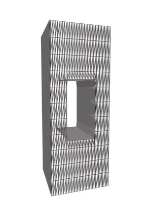
2 coding of various parts showing different features, the possibility of rotation or of hiding covering parts of the object's surface to gain an insight into hidden structures, crucial improvements are achieved where a 3D representation facilitates work. Generally, everywhere real illustrative material is not available or affordable a qualitative electronic visualization might replace the existence of a real object. The process of gaining spatial data is based on the "shape from structured light" method, described in [1], [9], and [8]. Laser lines are projected onto the object, afterwards these lines are detected in the image, and finally, vertices are transformed back to spatial data using triangulation. As for our environment, this procedure is described in [15] and [13]. Figure 1: Work-flow ofthe reconstruction process. Our approach and this paper are structured according to the work-flow ofthe reconstruction process, depicted in Figure 1. In Section 2, the surface of three-dimensional objects is geometrically reconstructed by triangulation of the input polygons (scanner data). Two algorithms, cross-section and marching cubes triangulation, are compared against each other, showing different behavior concerning the quality and the amount of triangles of the reconstructed objects. These two approaches were chosen among others ([10], [11] and [6]), since they profit from the characteristics of the input data, i.e. its organization in layers. Section 3 describes the mesh optimization step during reconstruction. For this step, an algorithm is chosen which allows control of the geometric deformation of the model while reducing the number of triangles based on a gradient criterion. Compared with other simplification algorithms ([20]) and level of detail (LOD) approximations ([17] and [3]), this approach allows an efficient optimization of the model while giving the possibility to control the committed error. Section 4 shows results computed out of synthetic and real data and the paper concludes with a discussion of the results and give an outlook on future work. 2 Reconstruction of Geometric Objects Supplied with the knowledge of the origin and the characteristics of the sampled data points that define the surface of the scanned object in layers, a general definition of a scanner mesh can be given as follows: ffl A scanner mesh (Figure 2a) is built up by a series of cross-sections. The route on which the scanning plane was moved over the object implicitly determines the order of the cross-sections. For some scanning procedures, this order is simply given along an axis; with respect to rotational cross- sections, the order of the series is equivalent to the degree of rotation. 2
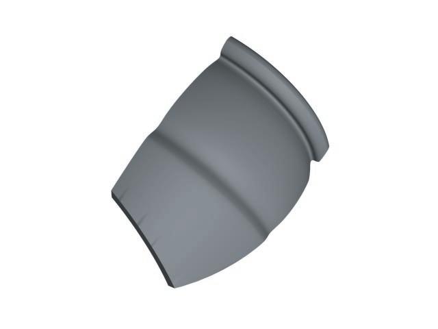
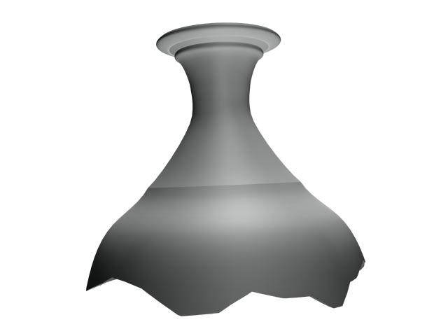
3 ffl A cross-section (Figure 2b) combines a set of planar contours retrieved by the intersection between the scanning plane and the object at a certain level. To keep the approach as general as possible, this level of abstraction is needed to allow the representation of multi-contoured objects or scenes containing several objects. ffl A contour (Figure 2c) is a planar polygon describing the shape of one object's contour at a certain level where the nodes of the polygon are ordered either clock wise or counter clock wise. (a) (b) (c) Figure 2: (a) definition of the scanner mesh, (b) cross-section, (c) contour. 2.1 Polygon Triangulation As illustrated in Figure 1, polygon triangulation is of central concern during the reconstruction process. Several strategies serving this purpose are described for example in [18]. For selecting an appropriate algorithm, let us first consider the demands of our application. No a-priori knowledge about the nature of the polygon can be assumed, that is, the algorithm has to work on any kind of polygon (convex and concave). Nevertheless, regarding the mode of operation of the scanning process, it is assured that such a polygon is free of intersection (Figure 3a), since, in order to produce a self-intersecting polygon, the scanning sensor must be able to sample the surface through the body of the object (Figure 3b). Furthermore, we do not allow the creation of new vertices on the polygon contour or inside the polygon to keep the visualization cost as low as possible. (a) (b) Figure 3: (a) the scanning device samples the surface of the objects, no polygon with intersection, (b) self-intersecting polygon, but impossible because the scanning device cannot sample through the object. Our heuristic approach is called "smallest inner angle first" which holds these demands. The algorithm systematically cuts off triangles from the polygon choosing the point with the smallest inner angle to be 3
4 the one to be removed from the polygon contour after building a triangle with its predecessor and successor node. Since the polygon is free of intersections, neither additional faces deform the contour of the model, nor vertices are dropped without being a member of a face. Figure 4 subsequently depicts the whole triangulation process for a simple polygon. In each step, the node with the smallest inner angle (bold) is selected and spans up a new triangle (dark shaded). Figure 4: Steps during polygon triangulation. In each step, a new triangle (dark shaded) is created around the polygon node having the smallest inner angle (bold). Figure 9d shows the result of the polygon triangulation algorithm applied on the contour polygon of the cerebrospinal fluid segmented from a CT scan, where we can notice one drawback ofthis algorithm: the occurrence of long triangles with an acute angle. To overcome this, the polygon re-tiling strategy proposed in [22] may be used. 2.2 Triangulation between Cross-Sections When examining cross-section triangulation, the actual problem can be formulated as follows [10]: for the bottom and top level cross- sections, reconstruct their surface by applying the polygon triangulation algorithm. Afterwards, for any pair of adjacent cross-sections, find a set of triangles (triangle-fan) which approximate the surface between these polygons with a minimal error according to the real surface of the object. Furthermore, the latter problem can be split up into the following two sub-problems: ffl An initial pair of vertices (P i,q i ) has to be found in order to define a start for the triangulation process. ffl For a given pair of vertices P j and Q j, the next point P j+1 or Q j+1 must be determined to define a triangle of the surface, together with P i and Q i. The selection criterion for the two vertices forming the initial pair of the triangulation algorithm must not be underestimated, since the quality of the triangulation process depends on these starting points (an inconvenient pair will result in distorted triangles in the triangle fan). A convenient initial pair should show similar features in respect with their polygons. The direction from the centroid C to a point is a stable feature if the distance from the point to the centroid is large (Figure 5a). Let u i and v i be vectors from the centroid to a point of the polygon's contour in the lower and upper cross-section. Now, the initial pair (P i,q j ) is selected such that the inner product of the vectors u i v j is a maximum. This guarantees an initial pair with similar features, i.e. peaks and 4
5 (a) (b) (c) Figure 5: (a) selection of the initial pair for cross-section triangulation, (b) finding the next vertex, (c) selection of the next vertex. direction of edges to neighboring polygon nodes. The direction of vector v i is taken into account, for the search for the maximum of the inner product, only nodes similar to Q i are regarded. Assume that the triangulation process has stopped after the last step leaving P i and Q i to be the points that are used for building the next triangle in the object's surface. Now either of the two vertices P i+1 or Q i+1 could be selected as the third point in the triangle. If P i+1 would be selected, the triangle (P i ;Q i ;P i+1 ) is generated and the resulting pair for the next triangulation step is (P i+1 ;Q i ). An intuitive criterion for this selection might be the length between the vertices, either P i+1 Q i or P i Q i+1. Choosing the triangle with the minimum area seems to be more natural since the original surface is approximated smoother. As for the situation in Figure 5b, P i+1 Q i is shorter than P i Q i+1 and (P i ;Q i ;P i+1 ) is designated to be processed next, leaving (P i+1 ;Q i ) the next pair. However, a criterion based on length only, fails to reproduce a natural-looking surface, if the horizontal position of the vertices is quite different (see Figure 5c). The current pair is (P i ;Q i ) and the x coordinate of P i is larger than the x coordinate of Q i. Now P i+1 Q i might be shorter than P i Q i+1 and (P i ;Q i ;P i+1 ) would be selected as the next triangle. Despite the length, the difference of direction is taken into account, because it is a more natural way for approximating the original surface. Let the difference in direction between P i P i+1 and Q i 1Q i be denoted by ff i and the one between P i 1P i and Q i Q i+1 be denoted by fi i. Now, the selection algorithm in the case of P i+1 Q i < P i ;Q i+1 determines the next pair as follows: If cos ff i >t select P i+1 otherwise if cos fi i >t select Q i+1 else select P i+1 where t is a threshold to handle the difference between the curvature of the lower and upper cross-section. The results show a more natural approximation of the surface although triangles might become larger. 2.3 Marching Cubes Triangulation One drawback concerning the triangulation with the angle criterion approach, is its inability to handle multicontoured structures. Since real world objects are single-contour primitives only rarely, complex handling 5

6 of such structures, e.g. combining simple objects to shape a more complex model, is needed. The Marching Cubes algorithm, introduced by William E. Lorensen and Harvey E. Cline [14], was designed to extract surface information from a 3D field of values and to overcome these difficulties. In order to show the method, first a two-dimensional equivalent of this approach is presented, know as Marching Squares and afterwards the procedure is expanded into 3D. Given a planar polygon (Figure 6a), the object's coordinate system is discretized with a regular grid, called the resolution of the Marching Squares algorithm (Figure 6b). Afterwards, each corner of every grid element is examined whether it lies inside or outside the polygon (Figure 6c). Now, from a lookup-table the algorithm extracts the information for each of the 24 possible cases for the corner matching the number and position of faces (if any) which represents the underlying polygon best. Finally, the source polygon becomes triangulated like given in Figure 6d. Nevertheless, this triangle set looks like a too-rough approximation of the original circle. (a) (b) (c) (d) (e) Figure 6: (a)-(d) steps during marching squares triangulation, (e) interpolation result. One obvious method to improve theaccuracy of the model is to increase the resolution of the raster, but this will lead to an exponential increase of triangles. A higher quality mesh with the same number of faces can be gained by applying interpolation inside the lookup square. Consider the square in Figure 7a. Corners 1 and 4 lie inside the object's contour, 2 and 3 do not. As a first step, the "marching square" suggests to generate face a and b which describe the actual shape of the polygon in the current raster square unsatisfactory (Figure 7b). (a) (b) (c) Figure 7: Edge interpolation inside a marching square (bold edges indicate membership of contour line - see text for details). Since we know the real coordinates of P i and P i+1 of the original polygon, we are able to interpolate the coordinates of the vertices fi 2 and fi 3 of face b and ff 3 of face a along the square's edges in order to obtain a more accurate approximation (Figure 7c). Figure 6e shows a triangle-mesh gained by theinterpolating Marching Squares algorithm applied to the polygon Figure 6a. 6

7 Now, having worked out the basic mechanism in two dimensions, we can consider the third dimension. Obviously, the former squares turn into cubes, giving rise to 28 possible cases for inside/outside corner combinations, which can be reduced to 15 base classes. The cube "marches" through object space returning a surface approximating set of triangles. Again, interpolation of vertex coordinates improves the quality of the model increasingly. If possible, interpolation is done along all three axis. The most powerful feature of the Marching Cube algorithm is its easiness to handle complex models, although the results are less accurate than using cross-section triangulation. The most aggravating drawback is the occurrence of huge sets of triangles. 3 Mesh Optimization Triangulation algorithms perform a straightforward process on their input data and tend to result in (typically heavily) over-tessellated meshes. Such meshes throw up problems concerning rendering, storing and transmission due to the enormous number of triangles they are built of. Therefore, decimation of triangles in a triangular mesh is required. One approach to speed up rendering is to replace a complex object by a level of detail (LOD) approximation (see [3], [7], [5] and [2] for examples). (a) (b) Figure 8: (a) original dragon mesh with triangles, (b) LOD approximation with triangles. However, towards our field of application where it is crucial to gain a precise representation rather than guarantee a high and/or fixed frame rate while rendering, these LOD approximations show a severe drawback (Figure 8): they might change both, the geometrical (Figure 8a) and topological (Figure 8b) features of the model. For the geometrical aspect, no reliable measure for the resulting contour change can be given. The topological transformations can result in converting non-manifold meshes into manifold counterparts. A triangle reduction function has to be found that preserves both, the non-manifold property and the contour of the input model. In [23], a method for reducing the surface description of triangulated models by adaptation to the object contour is presented. The error between the original and the simplified mesh is measured by the deviation of the spatial curvature. This allows approximations from a model where only redundancy is removed, i.e. triangles with equal normal vectors are merged, up to meshes showing a 7
8 similar contour like their original.the approach splits into four steps: 1. Creation of Free Polygons: During this step, a region growing process is performed. For each triangle of the object's, which is not already a member of any region, examine its neighbors and add them to the same region, if the following two conditions hold: ffl Each triangle of a region must have a common edge with another triangle of the same region. ffl For each pair of triangles out of one region, the angle between their normal vectors is less than a specified threshold a. Threshold a determines the curvature of a region. Using a small a, the region is nearly planar. According to an increasing value of a, the region will be more curved and the final approximation will become rough. If a = 0, the optimized model will erase redundancy in the original mesh, i.e. coplanar triangles will merge to form a region. 2. Projection of Polygons: In order to make re-triangulation possible in the last step of optimization, projecting a region onto a plane is required. The projection plane is defined by an average normal vector, which, according to [4], can be calculated as follows: Let m be the number of nodes in polygon P, V i = (x i ;y i ;z i ) be a node and j the successor index of i, j = i +1;i < m 1 and j = 0 with i = m 1. The average normal vector of P is defined by N x = mx (y i y j )(z i + z j ); N y = mx (z i z j )(x i + x j ); N z = i=1 i=1 i=1 mx (x i x j )(y i + y j ) (1) If the projected representation is not free of intersection, the region is left out of consideration and cannot be optimized. 3. Deleting Vertices from Polygon Contour: Another possibility for optimization is the elimination of vertices from the polygon contour that form a line with their predecessor and successor nodes. By deleting such a point, the model is decimated by one face. If for all m regions containing a point P the condition above isvalid, the optimization saves m triangles and additionally decreases the number of vertices of the mesh by one. 4. Retriangulation: Finally, retriangulation of these free polygons with the algorithm presented in Section 2.2 transforms all regions back to a homogenous, triangulated surface. 4 Results Figure 9a and Figure 9d represent the result from the polygon triangulation algorithm from Section 2.1 applied to a polygon of the cerebrospinal fluid segmented from a CT scan image. The original polygon consists of 154 polygon nodes, the triangulated mesh contains of 152 triangles, since no new vertices are generated. Figure 9b and Figure 9e demonstrate the cross-section algorithm described in Section 2.2. The 8
9
2D rendering takes a photo of the 2D scene with a virtual camera that selects an axis aligned rectangle from the scene. The photograph is placed into
 2D rendering takes a photo of the 2D scene with a virtual camera that selects an axis aligned rectangle from the scene. The photograph is placed into the viewport of the current application window. A pixel
CSC Computer Graphics
 // CSC. Computer Graphics Lecture Kasun@dscs.sjp.ac.lk Department of Computer Science University of Sri Jayewardanepura Polygon Filling Scan-Line Polygon Fill Algorithm Span Flood-Fill Algorithm Inside-outside
Depth. Common Classification Tasks. Example: AlexNet. Another Example: Inception. Another Example: Inception. Depth
 Common Classification Tasks Recognition of individual objects/faces Analyze object-specific features (e.g., key points) Train with images from different viewing angles Recognition of object classes Analyze
Scalar Visualization
 Scalar Visualization Visualizing scalar data Popular scalar visualization techniques Color mapping Contouring Height plots outline Recap of Chap 4: Visualization Pipeline 1. Data Importing 2. Data Filtering
L1 - Introduction. Contents. Introduction of CAD/CAM system Components of CAD/CAM systems Basic concepts of graphics programming
 L1 - Introduction Contents Introduction of CAD/CAM system Components of CAD/CAM systems Basic concepts of graphics programming 1 Definitions Computer-Aided Design (CAD) The technology concerned with the
Applications. Oversampled 3D scan data. ~150k triangles ~80k triangles
 Mesh Simplification Applications Oversampled 3D scan data ~150k triangles ~80k triangles 2 Applications Overtessellation: E.g. iso-surface extraction 3 Applications Multi-resolution hierarchies for efficient
Mesh Repairing and Simplification. Gianpaolo Palma
 Mesh Repairing and Simplification Gianpaolo Palma Mesh Repairing Removal of artifacts from geometric model such that it becomes suitable for further processing Input: a generic 3D model Output: (hopefully)a
AUTOMATED 4 AXIS ADAYfIVE SCANNING WITH THE DIGIBOTICS LASER DIGITIZER
 AUTOMATED 4 AXIS ADAYfIVE SCANNING WITH THE DIGIBOTICS LASER DIGITIZER INTRODUCTION The DIGIBOT 3D Laser Digitizer is a high performance 3D input device which combines laser ranging technology, personal
3-Dimensional Object Modeling with Mesh Simplification Based Resolution Adjustment
 3-Dimensional Object Modeling with Mesh Simplification Based Resolution Adjustment Özgür ULUCAY Sarp ERTÜRK University of Kocaeli Electronics & Communication Engineering Department 41040 Izmit, Kocaeli
Processing 3D Surface Data
 Processing 3D Surface Data Computer Animation and Visualisation Lecture 12 Institute for Perception, Action & Behaviour School of Informatics 3D Surfaces 1 3D surface data... where from? Iso-surfacing
Scalar Algorithms: Contouring
 Scalar Algorithms: Contouring Computer Animation and Visualisation Lecture tkomura@inf.ed.ac.uk Institute for Perception, Action & Behaviour School of Informatics Contouring Scaler Data Last Lecture...
Reconstruction of complete 3D object model from multi-view range images.
 Header for SPIE use Reconstruction of complete 3D object model from multi-view range images. Yi-Ping Hung *, Chu-Song Chen, Ing-Bor Hsieh, Chiou-Shann Fuh Institute of Information Science, Academia Sinica,
Processing 3D Surface Data
 Processing 3D Surface Data Computer Animation and Visualisation Lecture 17 Institute for Perception, Action & Behaviour School of Informatics 3D Surfaces 1 3D surface data... where from? Iso-surfacing
3D Modeling of Objects Using Laser Scanning
 1 3D Modeling of Objects Using Laser Scanning D. Jaya Deepu, LPU University, Punjab, India Email: Jaideepudadi@gmail.com Abstract: In the last few decades, constructing accurate three-dimensional models
Level Set Extraction from Gridded 2D and 3D Data
 Level Set Extraction from Gridded 2D and 3D Data David Eberly, Geometric Tools, Redmond WA 98052 https://www.geometrictools.com/ This work is licensed under the Creative Commons Attribution 4.0 International
Scalar Visualization
 Scalar Visualization 5-1 Motivation Visualizing scalar data is frequently encountered in science, engineering, and medicine, but also in daily life. Recalling from earlier, scalar datasets, or scalar fields,
Data Representation in Visualisation
 Data Representation in Visualisation Visualisation Lecture 4 Taku Komura Institute for Perception, Action & Behaviour School of Informatics Taku Komura Data Representation 1 Data Representation We have
Brain Surface Conformal Spherical Mapping
 Brain Surface Conformal Spherical Mapping Min Zhang Department of Industrial Engineering, Arizona State University mzhang33@asu.edu Abstract It is well known and proved that any genus zero surface can
Graphics and Interaction Rendering pipeline & object modelling
 433-324 Graphics and Interaction Rendering pipeline & object modelling Department of Computer Science and Software Engineering The Lecture outline Introduction to Modelling Polygonal geometry The rendering
Isosurface Rendering. CSC 7443: Scientific Information Visualization
 Isosurface Rendering What is Isosurfacing? An isosurface is the 3D surface representing the locations of a constant scalar value within a volume A surface with the same scalar field value Isosurfaces form
Watertight Planar Surface Reconstruction of Voxel Data
 Watertight Planar Surface Reconstruction of Voxel Data Eric Turner CS 284 Final Project Report December 13, 2012 1. Introduction There are many scenarios where a 3D shape is represented by a voxel occupancy
A Developer s Survey of Polygonal Simplification algorithms. CS 563 Advanced Topics in Computer Graphics Fan Wu Mar. 31, 2005
 A Developer s Survey of Polygonal Simplification algorithms CS 563 Advanced Topics in Computer Graphics Fan Wu Mar. 31, 2005 Some questions to ask Why simplification? What are my models like? What matters
11/1/13. Visualization. Scientific Visualization. Types of Data. Height Field. Contour Curves. Meshes
 CSCI 420 Computer Graphics Lecture 26 Visualization Height Fields and Contours Scalar Fields Volume Rendering Vector Fields [Angel Ch. 2.11] Jernej Barbic University of Southern California Scientific Visualization
Visualization. CSCI 420 Computer Graphics Lecture 26
 CSCI 420 Computer Graphics Lecture 26 Visualization Height Fields and Contours Scalar Fields Volume Rendering Vector Fields [Angel Ch. 11] Jernej Barbic University of Southern California 1 Scientific Visualization
Mesh Decimation Using VTK
 Mesh Decimation Using VTK Michael Knapp knapp@cg.tuwien.ac.at Institute of Computer Graphics and Algorithms Vienna University of Technology Abstract This paper describes general mesh decimation methods
Lecture notes: Object modeling
 Lecture notes: Object modeling One of the classic problems in computer vision is to construct a model of an object from an image of the object. An object model has the following general principles: Compact
Geometric Modeling. Bing-Yu Chen National Taiwan University The University of Tokyo
 Geometric Modeling Bing-Yu Chen National Taiwan University The University of Tokyo Surface Simplification Motivation Basic Idea of LOD Discrete LOD Continuous LOD Simplification Problem Characteristics
Handles. The justification: For a 0 genus triangle mesh we can write the formula as follows:
 Handles A handle in a 3d mesh is a through hole. The number of handles can be extracted of the genus of the 3d mesh. Genus is the number of times we can cut 2k edges without disconnecting the 3d mesh.
03 - Reconstruction. Acknowledgements: Olga Sorkine-Hornung. CSCI-GA Geometric Modeling - Spring 17 - Daniele Panozzo
 3 - Reconstruction Acknowledgements: Olga Sorkine-Hornung Geometry Acquisition Pipeline Scanning: results in range images Registration: bring all range images to one coordinate system Stitching/ reconstruction:
A Method of Automated Landmark Generation for Automated 3D PDM Construction
 A Method of Automated Landmark Generation for Automated 3D PDM Construction A. D. Brett and C. J. Taylor Department of Medical Biophysics University of Manchester Manchester M13 9PT, Uk adb@sv1.smb.man.ac.uk
Multi-View Matching & Mesh Generation. Qixing Huang Feb. 13 th 2017
 Multi-View Matching & Mesh Generation Qixing Huang Feb. 13 th 2017 Geometry Reconstruction Pipeline RANSAC --- facts Sampling Feature point detection [Gelfand et al. 05, Huang et al. 06] Correspondences
Generating 3D Meshes from Range Data
 Princeton University COS598B Lectures on 3D Modeling Generating 3D Meshes from Range Data Robert Kalnins Robert Osada Overview Range Images Optical Scanners Error sources and solutions Range Surfaces Mesh
Processing 3D Surface Data
 Processing 3D Surface Data Computer Animation and Visualisation Lecture 15 Institute for Perception, Action & Behaviour School of Informatics 3D Surfaces 1 3D surface data... where from? Iso-surfacing
Marching Cubes Robert Hunt CS 525. Introduction
 Marching Cubes Robert Hunt CS 525 Introduction The Marching Cubes algorithm is a method for visualizing a conceptual surface called an isosurface. An isosurface is formed from a set of points in 3 space
Computer Graphics 1. Chapter 2 (May 19th, 2011, 2-4pm): 3D Modeling. LMU München Medieninformatik Andreas Butz Computergraphik 1 SS2011
: 3D Modeling. LMU München Medieninformatik Andreas Butz Computergraphik 1 SS2011") Computer Graphics 1 Chapter 2 (May 19th, 2011, 2-4pm): 3D Modeling 1 The 3D rendering pipeline (our version for this class) 3D models in model coordinates 3D models in world coordinates 2D Polygons in
Computer Graphics 1 Chapter 2 (May 19th, 2011, 2-4pm): 3D Modeling 1 The 3D rendering pipeline (our version for this class) 3D models in model coordinates 3D models in world coordinates 2D Polygons in
Geometric Modeling. Mesh Decimation. Mesh Decimation. Applications. Copyright 2010 Gotsman, Pauly Page 1. Oversampled 3D scan data
 Applications Oversampled 3D scan data ~150k triangles ~80k triangles 2 Copyright 2010 Gotsman, Pauly Page 1 Applications Overtessellation: E.g. iso-surface extraction 3 Applications Multi-resolution hierarchies
A Survey of Volumetric Visualization Techniques for Medical Images
 International Journal of Research Studies in Computer Science and Engineering (IJRSCSE) Volume 2, Issue 4, April 2015, PP 34-39 ISSN 2349-4840 (Print) & ISSN 2349-4859 (Online) www.arcjournals.org A Survey
Visualization Computer Graphics I Lecture 20
 15-462 Computer Graphics I Lecture 20 Visualization Height Fields and Contours Scalar Fields Volume Rendering Vector Fields [Angel Ch. 12] April 15, 2003 Frank Pfenning Carnegie Mellon University http://www.cs.cmu.edu/~fp/courses/graphics/
Height Fields and Contours Scalar Fields Volume Rendering Vector Fields [Angel Ch. 12] April 23, 2002 Frank Pfenning Carnegie Mellon University
![Height Fields and Contours Scalar Fields Volume Rendering Vector Fields [Angel Ch. 12] April 23, 2002 Frank Pfenning Carnegie Mellon University](/thumbs/90/102611276.jpg "Height Fields and Contours Scalar Fields Volume Rendering Vector Fields [Angel Ch. 12] April 23, 2002 Frank Pfenning Carnegie Mellon University") 15-462 Computer Graphics I Lecture 21 Visualization Height Fields and Contours Scalar Fields Volume Rendering Vector Fields [Angel Ch. 12] April 23, 2002 Frank Pfenning Carnegie Mellon University http://www.cs.cmu.edu/~fp/courses/graphics/
15-462 Computer Graphics I Lecture 21 Visualization Height Fields and Contours Scalar Fields Volume Rendering Vector Fields [Angel Ch. 12] April 23, 2002 Frank Pfenning Carnegie Mellon University http://www.cs.cmu.edu/~fp/courses/graphics/
An Introduction to Geometric Modeling using Polygonal Meshes
 An Introduction to Geometric Modeling using Polygonal Meshes Joaquim Madeira Version 0.2 October 2014 U. Aveiro, October 2014 1 Main topics CG and affine areas Geometric Modeling Polygonal meshes Exact
CIS 4930/ SCIENTIFICVISUALIZATION
 CIS 4930/6930-902 SCIENTIFICVISUALIZATION ISOSURFACING Paul Rosen Assistant Professor University of South Florida slides credits Tricoche and Meyer ADMINISTRATIVE Read (or watch video): Kieffer et al,
Efficient Representation and Extraction of 2-Manifold Isosurfaces Using kd-trees
 Efficient Representation and Extraction of 2-Manifold Isosurfaces Using kd-trees Alexander Greß gress@cs.uni-bonn.de Reinhard Klein rk@cs.uni-bonn.de University of Bonn Institute of Computer Science II
FACET SHIFT ALGORITHM BASED ON MINIMAL DISTANCE IN SIMPLIFICATION OF BUILDINGS WITH PARALLEL STRUCTURE
 FACET SHIFT ALGORITHM BASED ON MINIMAL DISTANCE IN SIMPLIFICATION OF BUILDINGS WITH PARALLEL STRUCTURE GE Lei, WU Fang, QIAN Haizhong, ZHAI Renjian Institute of Surveying and Mapping Information Engineering
Advanced 3D-Data Structures
 Advanced 3D-Data Structures Eduard Gröller, Martin Haidacher Institute of Computer Graphics and Algorithms Vienna University of Technology Motivation For different data sources and applications different
Geometric Algorithms in Three Dimensions Tutorial. FSP Seminar, Strobl,
 Geometric Algorithms in Three Dimensions Tutorial FSP Seminar, Strobl, 22.06.2006 Why Algorithms in Three and Higher Dimensions Which algorithms (convex hulls, triangulations etc.) can be generalized to
3D Modeling: Surfaces
 CS 430/536 Computer Graphics I 3D Modeling: Surfaces Week 8, Lecture 16 David Breen, William Regli and Maxim Peysakhov Geometric and Intelligent Computing Laboratory Department of Computer Science Drexel
3/1/2010. Acceleration Techniques V1.2. Goals. Overview. Based on slides from Celine Loscos (v1.0)
") Acceleration Techniques V1.2 Anthony Steed Based on slides from Celine Loscos (v1.0) Goals Although processor can now deal with many polygons (millions), the size of the models for application keeps on
Acceleration Techniques V1.2 Anthony Steed Based on slides from Celine Loscos (v1.0) Goals Although processor can now deal with many polygons (millions), the size of the models for application keeps on
Alex Li 11/20/2009. Chris Wojtan, Nils Thurey, Markus Gross, Greg Turk
 Alex Li 11/20/2009 Chris Wojtan, Nils Thurey, Markus Gross, Greg Turk duction Overview of Lagrangian of Topological s Altering the Topology 2 Presents a method for accurately tracking the moving surface
Scientific Visualization. CSC 7443: Scientific Information Visualization
 Scientific Visualization Scientific Datasets Gaining insight into scientific data by representing the data by computer graphics Scientific data sources Computation Real material simulation/modeling (e.g.,
Contours & Implicit Modelling 4
 Brief Recap Contouring & Implicit Modelling Contouring Implicit Functions Visualisation Lecture 8 lecture 6 Marching Cubes lecture 3 visualisation of a Quadric toby.breckon@ed.ac.uk Computer Vision Lab.
Edge and local feature detection - 2. Importance of edge detection in computer vision
 Edge and local feature detection Gradient based edge detection Edge detection by function fitting Second derivative edge detectors Edge linking and the construction of the chain graph Edge and local feature
Volume visualization. Volume visualization. Volume visualization methods. Sources of volume visualization. Sources of volume visualization
 Volume visualization Volume visualization Volumes are special cases of scalar data: regular 3D grids of scalars, typically interpreted as density values. Each data value is assumed to describe a cubic
DATA MODELS IN GIS. Prachi Misra Sahoo I.A.S.R.I., New Delhi
 DATA MODELS IN GIS Prachi Misra Sahoo I.A.S.R.I., New Delhi -110012 1. Introduction GIS depicts the real world through models involving geometry, attributes, relations, and data quality. Here the realization
Surface Reconstruction. Gianpaolo Palma
 Surface Reconstruction Gianpaolo Palma Surface reconstruction Input Point cloud With or without normals Examples: multi-view stereo, union of range scan vertices Range scans Each scan is a triangular mesh
Contouring and Isosurfaces. Ronald Peikert SciVis Contouring 2-1
 Contouring and Isosurfaces Ronald Peikert SciVis 2007 - Contouring 2-1 What are contours? Set of points where the scalar field s has a given value c: Examples in 2D: height contours on maps isobars on
A TESSELLATION FOR ALGEBRAIC SURFACES IN CP 3
 A TESSELLATION FOR ALGEBRAIC SURFACES IN CP 3 ANDREW J. HANSON AND JI-PING SHA In this paper we present a systematic and explicit algorithm for tessellating the algebraic surfaces (real 4-manifolds) F
Scalar Data. Visualization Torsten Möller. Weiskopf/Machiraju/Möller
 Scalar Data Visualization Torsten Möller Weiskopf/Machiraju/Möller Overview Basic strategies Function plots and height fields Isolines Color coding Volume visualization (overview) Classification Segmentation
Geometric Modeling. Introduction
 Geometric Modeling Introduction Geometric modeling is as important to CAD as governing equilibrium equations to classical engineering fields as mechanics and thermal fluids. intelligent decision on the
Einführung in Visual Computing
 Einführung in Visual Computing 186.822 Rasterization Werner Purgathofer Rasterization in the Rendering Pipeline scene objects in object space transformed vertices in clip space scene in normalized device
SEOUL NATIONAL UNIVERSITY
 Fashion Technology 5. 3D Garment CAD-1 Sungmin Kim SEOUL NATIONAL UNIVERSITY Overview Design Process Concept Design Scalable vector graphics Feature-based design Pattern Design 2D Parametric design 3D
Visualization. Images are used to aid in understanding of data. Height Fields and Contours Scalar Fields Volume Rendering Vector Fields [chapter 26]
![Visualization. Images are used to aid in understanding of data. Height Fields and Contours Scalar Fields Volume Rendering Vector Fields [chapter 26]](/thumbs/74/70771954.jpg "Visualization. Images are used to aid in understanding of data. Height Fields and Contours Scalar Fields Volume Rendering Vector Fields [chapter 26]") Visualization Images are used to aid in understanding of data Height Fields and Contours Scalar Fields Volume Rendering Vector Fields [chapter 26] Tumor SCI, Utah Scientific Visualization Visualize large
Visualization Images are used to aid in understanding of data Height Fields and Contours Scalar Fields Volume Rendering Vector Fields [chapter 26] Tumor SCI, Utah Scientific Visualization Visualize large
Chapter 1. Introduction
 Introduction 1 Chapter 1. Introduction We live in a three-dimensional world. Inevitably, any application that analyzes or visualizes this world relies on three-dimensional data. Inherent characteristics
Mesh Decimation. Mark Pauly
 Mesh Decimation Mark Pauly Applications Oversampled 3D scan data ~150k triangles ~80k triangles Mark Pauly - ETH Zurich 280 Applications Overtessellation: E.g. iso-surface extraction Mark Pauly - ETH Zurich
Preferred directions for resolving the non-uniqueness of Delaunay triangulations
 Preferred directions for resolving the non-uniqueness of Delaunay triangulations Christopher Dyken and Michael S. Floater Abstract: This note proposes a simple rule to determine a unique triangulation
COMP30019 Graphics and Interaction Rendering pipeline & object modelling
 COMP30019 Graphics and Interaction Rendering pipeline & object modelling Department of Computer Science and Software Engineering The Lecture outline Introduction to Modelling Polygonal geometry The rendering
Lecture outline. COMP30019 Graphics and Interaction Rendering pipeline & object modelling. Introduction to modelling
 Lecture outline COMP30019 Graphics and Interaction Rendering pipeline & object modelling Department of Computer Science and Software Engineering The Introduction to Modelling Polygonal geometry The rendering
Geometry Vocabulary. acute angle-an angle measuring less than 90 degrees
 Geometry Vocabulary acute angle-an angle measuring less than 90 degrees angle-the turn or bend between two intersecting lines, line segments, rays, or planes angle bisector-an angle bisector is a ray that
Practical Linear Algebra: A Geometry Toolbox
 Practical Linear Algebra: A Geometry Toolbox Third edition Chapter 18: Putting Lines Together: Polylines and Polygons Gerald Farin & Dianne Hansford CRC Press, Taylor & Francis Group, An A K Peters Book
CS 4620 Midterm, March 21, 2017
 CS 460 Midterm, March 1, 017 This 90-minute exam has 4 questions worth a total of 100 points. Use the back of the pages if you need more space. Academic Integrity is expected of all students of Cornell
Chapter 4. Chapter 4. Computer Graphics 2006/2007 Chapter 4. Introduction to 3D 1
 Chapter 4 Chapter 4 Chapter 4. Introduction to 3D graphics 4.1 Scene traversal 4.2 Modeling transformation 4.3 Viewing transformation 4.4 Clipping 4.5 Hidden faces removal 4.6 Projection 4.7 Lighting 4.8
Scalar Field Visualization I
 Scalar Field Visualization I What is a Scalar Field? The approximation of certain scalar function in space f(x,y,z). Image source: blimpyb.com f What is a Scalar Field? The approximation of certain scalar
Iso-surface cell search. Iso-surface Cells. Efficient Searching. Efficient search methods. Efficient iso-surface cell search. Problem statement:
 Iso-Contouring Advanced Issues Iso-surface cell search 1. Efficiently determining which cells to examine. 2. Using iso-contouring as a slicing mechanism 3. Iso-contouring in higher dimensions 4. Texturing
Texture Mapping using Surface Flattening via Multi-Dimensional Scaling
 Texture Mapping using Surface Flattening via Multi-Dimensional Scaling Gil Zigelman Ron Kimmel Department of Computer Science, Technion, Haifa 32000, Israel and Nahum Kiryati Department of Electrical Engineering
Character Modeling COPYRIGHTED MATERIAL
 38 Character Modeling p a r t _ 1 COPYRIGHTED MATERIAL 39 Character Modeling Character Modeling 40 1Subdivision & Polygon Modeling Many of Maya's features have seen great improvements in recent updates
Volume Illumination, Contouring
 Volume Illumination, Contouring Computer Animation and Visualisation Lecture 0 tkomura@inf.ed.ac.uk Institute for Perception, Action & Behaviour School of Informatics Contouring Scaler Data Overview -
3 Polygonal Modeling. Getting Started with Maya 103
 3 Polygonal Modeling In Maya, modeling refers to the process of creating virtual 3D surfaces for the characters and objects in the Maya scene. Surfaces play an important role in the overall Maya workflow
Extracting Surface Representations From Rim Curves
 Extracting Surface Representations From Rim Curves Hai Chen 1, Kwan-Yee K. Wong 2, Chen Liang 2, and Yue Chen 1 1 College of Software Technology, Zhejiang University, Hangzhou, Zhejiang, China 310027 chenhai@gmail.com
Scene Management. Video Game Technologies 11498: MSc in Computer Science and Engineering 11156: MSc in Game Design and Development
 Video Game Technologies 11498: MSc in Computer Science and Engineering 11156: MSc in Game Design and Development Chap. 5 Scene Management Overview Scene Management vs Rendering This chapter is about rendering
Final Project, Digital Geometry Processing
 Final Project, Digital Geometry Processing Shayan Hoshyari Student #: 81382153 December 2016 Introduction In this project an adaptive surface remesher has been developed based on the paper [1]. An algorithm
Visualization Computer Graphics I Lecture 20
 15-462 Computer Graphics I Lecture 20 Visualization Height Fields and Contours Scalar Fields Volume Rendering Vector Fields [Angel Ch. 12] November 20, 2003 Doug James Carnegie Mellon University http://www.cs.cmu.edu/~djames/15-462/fall03
The Full Survey on The Euclidean Steiner Tree Problem
 The Full Survey on The Euclidean Steiner Tree Problem Shikun Liu Abstract The Steiner Tree Problem is a famous and long-studied problem in combinatorial optimization. However, the best heuristics algorithm
Indirect Volume Rendering
 Indirect Volume Rendering Visualization Torsten Möller Weiskopf/Machiraju/Möller Overview Contour tracing Marching cubes Marching tetrahedra Optimization octree-based range query Weiskopf/Machiraju/Möller
Efficient Representation and Extraction of 2-Manifold Isosurfaces Using kd-trees
 Efficient Representation and Extraction of 2-Manifold Isosurfaces Using kd-trees Alexander Greß and Reinhard Klein University of Bonn Institute of Computer Science II Römerstraße 164, 53117 Bonn, Germany
3D Surface Reconstruction of the Brain based on Level Set Method
 3D Surface Reconstruction of the Brain based on Level Set Method Shijun Tang, Bill P. Buckles, and Kamesh Namuduri Department of Computer Science & Engineering Department of Electrical Engineering University
1. Interpreting the Results: Visualization 1
 1. Interpreting the Results: Visualization 1 visual/graphical/optical representation of large sets of data: data from experiments or measurements: satellite images, tomography in medicine, microsopy,...
SURFACE CONSTRUCTION USING TRICOLOR MARCHING CUBES
 SURFACE CONSTRUCTION USING TRICOLOR MARCHING CUBES Shaojun Liu, Jia Li Oakland University Rochester, MI 4839, USA Email: sliu2@oakland.edu, li4@oakland.edu Xiaojun Jing Beijing University of Posts and
SUPPLEMENTARY FILE S1: 3D AIRWAY TUBE RECONSTRUCTION AND CELL-BASED MECHANICAL MODEL. RELATED TO FIGURE 1, FIGURE 7, AND STAR METHODS.
 SUPPLEMENTARY FILE S1: 3D AIRWAY TUBE RECONSTRUCTION AND CELL-BASED MECHANICAL MODEL. RELATED TO FIGURE 1, FIGURE 7, AND STAR METHODS. 1. 3D AIRWAY TUBE RECONSTRUCTION. RELATED TO FIGURE 1 AND STAR METHODS
Project Updates Short lecture Volumetric Modeling +2 papers
 Volumetric Modeling Schedule (tentative) Feb 20 Feb 27 Mar 5 Introduction Lecture: Geometry, Camera Model, Calibration Lecture: Features, Tracking/Matching Mar 12 Mar 19 Mar 26 Apr 2 Apr 9 Apr 16 Apr 23
Dynamic 3D Shape From Multi-viewpoint Images Using Deformable Mesh Model
 Dynamic 3D Shape From Multi-viewpoint Images Using Deformable Mesh Model Shohei Nobuhara Takashi Matsuyama Graduate School of Informatics, Kyoto University Sakyo, Kyoto, 606-8501, Japan {nob, tm}@vision.kuee.kyoto-u.ac.jp
Range Imaging Through Triangulation. Range Imaging Through Triangulation. Range Imaging Through Triangulation. Range Imaging Through Triangulation
 Obviously, this is a very slow process and not suitable for dynamic scenes. To speed things up, we can use a laser that projects a vertical line of light onto the scene. This laser rotates around its vertical
Overview. Efficient Simplification of Point-sampled Surfaces. Introduction. Introduction. Neighborhood. Local Surface Analysis
 Overview Efficient Simplification of Pointsampled Surfaces Introduction Local surface analysis Simplification methods Error measurement Comparison PointBased Computer Graphics Mark Pauly PointBased Computer
Outline of the presentation
 Surface Reconstruction Petra Surynková Charles University in Prague Faculty of Mathematics and Physics petra.surynkova@mff.cuni.cz Outline of the presentation My work up to now Surfaces of Building Practice
Parallel Computation of Spherical Parameterizations for Mesh Analysis. Th. Athanasiadis and I. Fudos University of Ioannina, Greece
 Parallel Computation of Spherical Parameterizations for Mesh Analysis Th. Athanasiadis and I. Fudos, Greece Introduction Mesh parameterization is a powerful geometry processing tool Applications Remeshing
Cell Decomposition for Building Model Generation at Different Scales
 Cell Decomposition for Building Model Generation at Different Scales Norbert Haala, Susanne Becker, Martin Kada Institute for Photogrammetry Universität Stuttgart Germany forename.lastname@ifp.uni-stuttgart.de
Mesh and Mesh Simplification
 Slide Credit: Mirela Ben-Chen Mesh and Mesh Simplification Qixing Huang Mar. 21 st 2018 Mesh DataStructures Data Structures What should bestored? Geometry: 3D coordinates Attributes e.g. normal, color,
Decimation of 2D Scalar Data with Error Control
 Decimation of 2D Scalar Data with Error Control Daniel R. Schikore Chandrajit L. Bajaj Department of Computer Sciences Purdue University West Lafayette, IN 47907 drs@cs.purdue.edu bajaj@cs.purdue.edu Abstract
APPROACH FOR MESH OPTIMIZATION AND 3D WEB VISUALIZATION
 APPROACH FOR MESH OPTIMIZATION AND 3D WEB VISUALIZATION Pavel I. Hristov 1, Emiliyan G. Petkov 2 1 Pavel I. Hristov Faculty of Mathematics and Informatics, St. Cyril and St. Methodius University, Veliko
Contours & Implicit Modelling 1
 Contouring & Implicit Modelling Visualisation Lecture 8 Institute for Perception, Action & Behaviour School of Informatics Contours & Implicit Modelling 1 Brief Recap Contouring Implicit Functions lecture
Fast marching methods
 1 Fast marching methods Lecture 3 Alexander & Michael Bronstein tosca.cs.technion.ac.il/book Numerical geometry of non-rigid shapes Stanford University, Winter 2009 Metric discretization 2 Approach I:
MARCHING CUBES AND VARIANTS
 CHAPTER MARCHING CUBES AND VARIANTS In the introduction, we mentioned four different approaches to isosurface construction. In this chapter, we describe one of those approaches to isosurface construction,