L1 - Introduction. Contents. Introduction of CAD/CAM system Components of CAD/CAM systems Basic concepts of graphics programming
|
|
|
- Tobias Osborne
- 6 years ago
- Views:
Transcription


1 L1 - Introduction Contents Introduction of CAD/CAM system Components of CAD/CAM systems Basic concepts of graphics programming 1
2 Definitions Computer-Aided Design (CAD) The technology concerned with the use of computer system to assist in the creation, modification, analysis, and optimization of a design. A computer program that embodies computer graphics and an application program facilitating engineering functions in the design process From geometric tools for manipulating shapes (at one extreme) to those for analysis and optimization (at the other extreme) Basic role of CAD is to define the geometry of design because the geometry of the design is essential to all the subsequent activities in the product cycle 2
 Computer-Aided Manufacturing (CAM) The technology concerned with the use of computer systems to plan, manage, and control manufacturing operations through either direct or indirect computer")
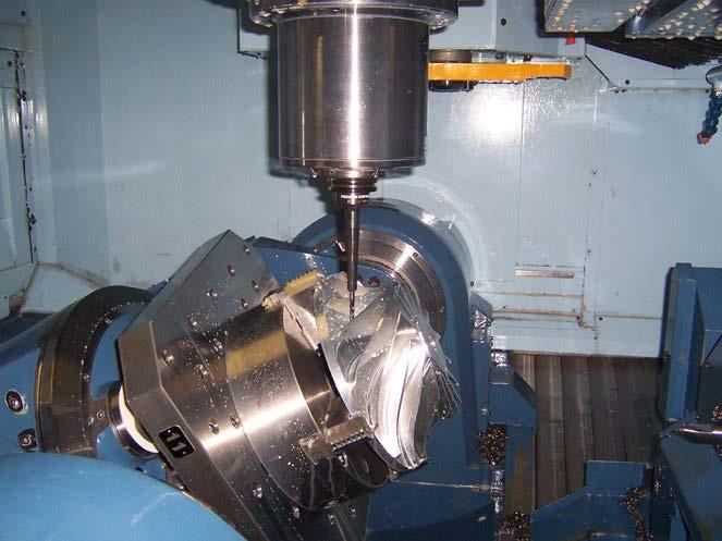
3 Definition (cont.) Computer-Aided Manufacturing (CAM) The technology concerned with the use of computer systems to plan, manage, and control manufacturing operations through either direct or indirect computer interface with the plant s production resources. One of the most mature areas of CAM is numerical control (NC) Control a machine tool for grinding, cutting, milling, punching, bending or turning raw stock into a finished part Another significant CAM function is the programming of robots May operate in a work-cell arrangement, selecting and positioning tools and work-pieces for NC machines 3

4 Modern Product Cycle CAD/CAM plays a very important role 4

5 Modern Product Cycle (cont.) 5
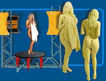
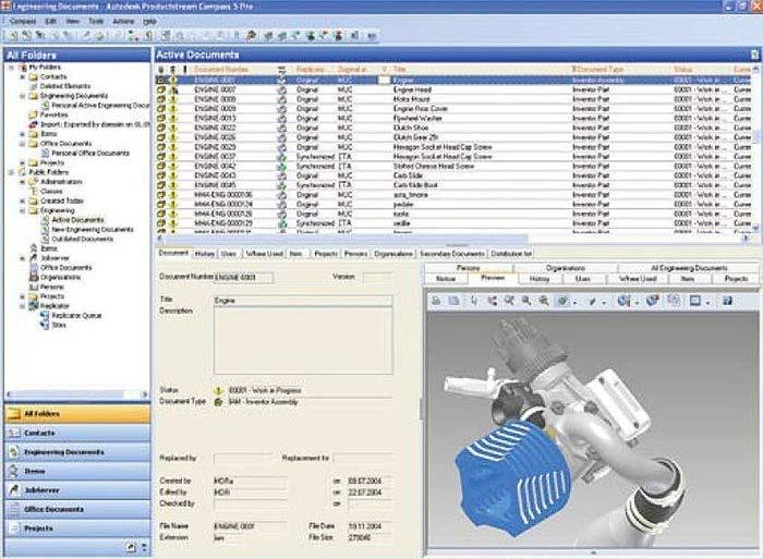
6 Using CAD/CAM/CAM System for Product Development Some Examples A story of engineering design team ( NX7 product development productivity redefined ( Jewelry industry ( bedded&v=hu_krfkdyi8) 6
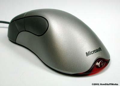
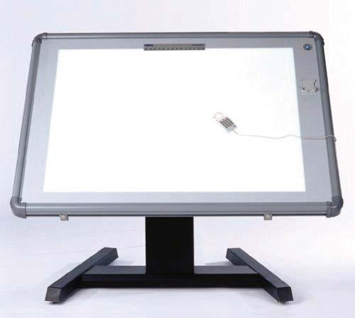
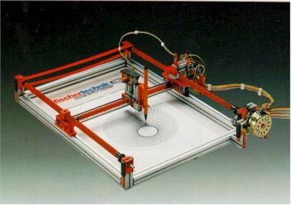
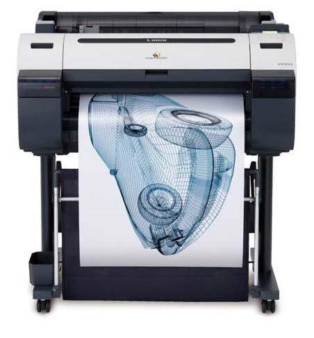
7 Hardware Components of CAD/CAM Systems 7
 monitor Scanning")


8 Raster Graphics Devices Cathode Ray Tube (CRT) monitor Scanning pattern for raster refresh A raster graphics image, or bitmap, is a data structure representing a generally rectangular grid of pixels, or points of color, Viewable via a monitor, paper, etc 8
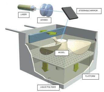
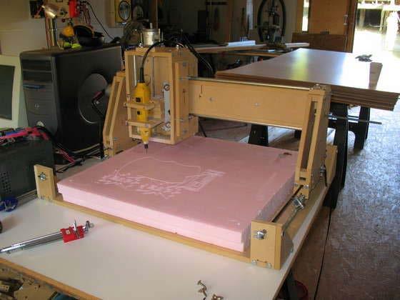
9 Manufacturing Components of CAD/CAM 9
10 Software Components 10
11 Basic Concepts of Graphics Programming World coordinate system The unique reference coordinate system used to describe what the world of interest looks like. Model coordinate system Each object in the world has its own reference coordinate system, i.e., its model coordinate system. Two models coordinate systems can be different Viewing coordinate system A reference coordinate system used for projecting all the points in the threedimensional objects onto the computer monitor (two-dimensional) to be seen by human eyes. By convention, in a viewing coordinate system, the z-axis is the viewing direction and is perpendicular to the monitor screen. 11
12 Coordinate Systems Conversion Model to World coordinate system Different parts of their own MCS assembled together with a single WCS. World to View coordinate system Convert WCS to VCS, and project the object onto the computer screen (parallel and perspective projection). VCS to virtual device coordinate system Convert the rectangle of the screen in VCS to a normalized 2D coordinate system (u,v). VDCS to specific device coordinate system 12
13 Transformation Matrix To convert a point in one coordinate system to another (for example, from MCS to WCS), a 4x4 matrix is used to achieve the task. Different types of transformation matrix Translation Rotation about one coordinate axis Rotation about an arbitrary coordinate axis Composition of translations and rotations Others 13
14 Translation The x-y-z axes of MCS are parallel to the x-y-z axes of WCS 14
15 Rotation about the x-axis MCS is rotated about the x-axis of WCS, with the origin unchanged. 15
16 Rotation about the Principle Axes MCS is rotated about the x-, y- or z-axis of WCS, with the origin unchanged. 16
17 Composition Series of translations and rotations concatenated together in a single matrix 17
18 Rotation about an Arbitrary Axis MCS is rotated about an arbitrary vector in WCS, with the origin unchanged. 18
19 19
20 Mapping The 4x4 transformation matrix T1-2 between two given coordinate systems Two methods to compute: Calculate the product of the transformation matrices, or Solving the linear equations to find the elements in T1-2 by selecting 4 pairs of corresponding points in the two coordinate systems. 20
21 Scaling Other Transformation Matrices Shearing (z-axis) 21
22 Shearing question: Can a cube become a curved barrel after a shearing transformation? 22

23 Affine Transformation Transformation made of translation, rotation, scaling, and shearing 23
24 Hidden-Line and Hidden-Surface Removal Types of algorithms Visible-line determination: examine edge geometry, and determine edge segments that are visible or are hidden (efficiency is the major problem) Z-buffer: device-precision algorithm that records the visible object found at each pixel Area subdivision algorithms: divide-and-conquer applied to object areas Ray tracing: determine visible object by tracing line from user eye to each pixel in scene Useful link: nlines/ 24
 is stored in a buffer. Is arranged as a 2D array (x-y) with one element for each screen pixel When depths conflict: a close object hides a farther one (called z-culling).")
25 z-buffering The most widely used technique Raster-graphics based Efficient Also known as depth buffering When an object is rendered by a 3D graphics card, the depth of a generated pixel (z coordinate) is stored in a buffer. Is arranged as a 2D array (x-y) with one element for each screen pixel When depths conflict: a close object hides a farther one (called z-culling). 25


26 Ray Tracing A technique for generating an image by tracing the path of light through pixels in an image plane and simulating the effects of its encounters with virtual objects 26


27 Basic Light Reflection Model For a perfect mirror surface the angle of reflection is equal to the angle of incidence However, many more factors need to be considered Direct light Ambient light Reflected light Etc. Global illumination 27

28 Geometric Modeling Systems Contents Wireframe modeling system Surface modeling system Solid modeling system (Most widely used) Non-manifold modeling system (CAE system) Mesh generation for manufacturing and analysis What is geometric modeling system? A computer system to model the geometry of a part It provides an environment similar to the one in which the physical model is created and naturally manipulated. The designer deforms, adds, and cuts pieces off the visual model in the process of detailing a shape (virtually) 28
 No volumetric info Ambiguous when displaying a solid")
29 Wireframe Modeling Systems Represents a shape by its characteristic lines and end points (60 s and 70 s) Advantages: Requires less computer speed and memory Does not require sophisticated math Disadvantages: Can t handle solid parts with inside/outside info Difficult to visualize (just wires) No volumetric info Ambiguous when displaying a solid model

30 A wireframe model of a car hood 30
31 Surface Modeling Systems In addition to the characteristic curves and end points and their connectivity information, surface information is also included (70 s and 80 ) Two main purposes: visual model used for evaluating the model aesthetically math description is used to generate NC tool path to machine the surfaces Major disadvantage: Still can t model a solid part Can t calculate volumetric properties such as mass, weight, etc. 31

32 A surface model of a shoe s bottom 32

33 A surface model of a car s body 33


34 Solid Modeling Systems It models a shape that forms a closed volume, called a solid. In addition to all the functions provided by a surface modeling system, it contains the information that determines whether any location is inside, outside, or on the closed volume (80 s and 90 s) Must be a closed model 34
35 Modeling Functions Primitive creation functions Most used analytical shapes such as blocks, cylinders, cones, wedges, torus, sphere, etc. Boolean operations To provide the user a suite of Boolean operations that can combine primitives into other geometric shapes Sweeping, Skinning, Rounding (or blending) Sweeping: sweep a planar closed curve (profile curve) along another 3D curve (path curve) Skinning: creating a skin surface over pre-specified cross-sectional planar surfaces (a construction example) Feature based modeling Model a solid by pre-set features such as slots, holes, chamfers (via subgraph) 35

36 Primitive Creation and Boolean Operations Primitives generally supported 36
37 Sweeping Operation 37

38 Skinning Operation 38
39 39


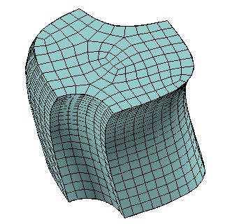
40 General Skinning Operation Example: Reconstructing Bone Joint from CT Scans 40

41 Rounding Operation 41

42 Feature Based Modeling 42
43 Data Structure Once a model is created, its exact mathematical description is also defined. But how is this description stored in a solid modeling system? Three types of data structures used in a solid modeling system to describe a solid Constructive Solid Geometry (CSG) tree structure Boundary Representation (B-rep) data structure Decomposition model structure 43
44 CSG Tree Structure A data structure that stores the history of applying Boolean operations on the primitives 44
45 CSG Tree Structure (cont.) Advantages: Simple and compact data, management of data is easy The solid stored in a CSG is always a valid solid Always convertible to other types of rep., such as B-rep Parametric modeling can be realized easily by changing the parameter values of the associated primitives Disadvantages: Limited modeling ability. Only primitives and their Boolean operations; no sweeps or lofts Computationally expensive and difficult to derive the boundary data (faces, edges, vertices) and their topology, needed for: Display of the model (faces and edges needed) Calculation of volumetric data such as mass and centroid 45
) A convenient organization for storing geometric data is to create three lists: - A vertex table, an edge table, and a polygon table An alternative arrangement is to use just")
46 B-rep Data Structure Drawback of CSG-tree => a hybrid representation of CSG and B-rep Basic elements composing the boundary of a solid are faces, edges, and vertices (simplest example of B-Rep (already shown earlier)) A convenient organization for storing geometric data is to create three lists: - A vertex table, an edge table, and a polygon table An alternative arrangement is to use just two tables: - A vertex table and a polygon table (e.g., OBJ file) 46
47 Problems with this simple B-Rep Unable to represent a face with two loops Hard to answer queries like what is the edge shared by two faces 47
 Linked list only A")

48 Half-edge and Winged-edge Data Structure Half-edge (link) Double linked list as the primitive data structure Better than the table based Still hard to process model with holes without splitting Winged-edge (link) Linked list only A edge table with winged edges - A face table - A node table - Can process faces with multiple holes more easily (For a face with inner loops, the outer boundary is ordered clockwise, while its inner loops, if any, are ordered counter clockwise) 48

49 Decomposition Model Structure A solid model is described approximately as an aggregate of simple solids such as cubes. Voxel representation: To represent a solid by equal-sized cubes, called voxels Simple and easy to develop Memory intensive data structure Resolution cannot be high It is inherently an approximation Oct-tree (Octree) representation: To represent a solid by a number of non-equal-sized hexahedra Adaptive to the shape of model to be presented 49
50 Octree Representation 50
51 Boolean Operations of Simple Polygons 1. Efficiently find all the intersection points between the edges of A and B. 2. Segment the edges of A and B by the intersection points. 3. Trace the segmented A and B to find the correct Boolean result. 51
52 Regularization The result of a Boolean operation must preserve the dimensionality and homogeneity of the initial objects A and B are 2D sets, but the theoretical A B is a line which is 1D. By regularization, A B = φ (empty). 52

53 Regularized Boolean Operations 53
54 Boolean Operations in 3D 54


55 Nonmanifold Modeling Systems Further extension of solid modeling 55


56 Assembly Modeling Provide a logical structure for grouping and organizing parts into assemblies Maintain the relationships between the parts and the associated data: Mating relationship Parametric constraint relationship Clearance/non-interference relationship Automatic determination of assembly ordering 56
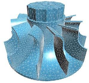
57 Mesh Generation Process Mesh Vertices Apply Manual Sizing, Match Intervals Mesh Curves Verify/correct for sizing criteria on curves For each surface Set up sizing function for surface Mesh surface Smooth/Cleanup surface mesh Verify Quality For each volume Set up sizing function for volume Mesh volume Smooth/Cleanup volume mesh Verify Quality The Mesh Generation Process 57
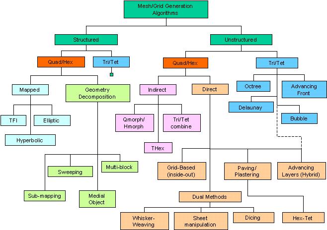
58 Meshing Algorithms 58
Geometric Modeling. Introduction
 Geometric Modeling Introduction Geometric modeling is as important to CAD as governing equilibrium equations to classical engineering fields as mechanics and thermal fluids. intelligent decision on the
Solid Modeling. Ron Goldman Department of Computer Science Rice University
 Solid Modeling Ron Goldman Department of Computer Science Rice University Solids Definition 1. A model which has a well defined inside and outside. 2. For each point, we can in principle determine whether
SEOUL NATIONAL UNIVERSITY
 Fashion Technology 5. 3D Garment CAD-1 Sungmin Kim SEOUL NATIONAL UNIVERSITY Overview Design Process Concept Design Scalable vector graphics Feature-based design Pattern Design 2D Parametric design 3D
Computer Aided Engineering Applications
 Computer Aided Engineering Applications 1A.Geometric Modeling 1.1 Geometric modelling methods 1.2 Data representation 1.3 Modeling functions 1.4 Structure of a CAD system Engi 6928 - Fall 2014 1.Geometric
Chapter 12 Solid Modeling. Disadvantages of wireframe representations
 Chapter 12 Solid Modeling Wireframe, surface, solid modeling Solid modeling gives a complete and unambiguous definition of an object, describing not only the shape of the boundaries but also the object
Introduction to Solid Modeling Parametric Modeling. Mechanical Engineering Dept.
 Introduction to Solid Modeling Parametric Modeling 1 Why draw 3D Models? 3D models are easier to interpret. Simulation under real-life conditions. Less expensive than building a physical model. 3D models
Physically-Based Modeling and Animation. University of Missouri at Columbia
 Overview of Geometric Modeling Overview 3D Shape Primitives: Points Vertices. Curves Lines, polylines, curves. Surfaces Triangle meshes, splines, subdivision surfaces, implicit surfaces, particles. Solids
CSG obj. oper3. obj1 obj2 obj3. obj5. obj4
 Solid Modeling Solid: Boundary + Interior Volume occupied by geometry Solid representation schemes Constructive Solid Geometry (CSG) Boundary representations (B-reps) Space-partition representations Operations
MODELING AND HIERARCHY
 MODELING AND HIERARCHY Introduction Models are abstractions of the world both of the real world in which we live and of virtual worlds that we create with computers. We are all familiar with mathematical
Lecture 17: Solid Modeling.... a cubit on the one side, and a cubit on the other side Exodus 26:13
 Lecture 17: Solid Modeling... a cubit on the one side, and a cubit on the other side Exodus 26:13 Who is on the LORD's side? Exodus 32:26 1. Solid Representations A solid is a 3-dimensional shape with
9. Three Dimensional Object Representations
 9. Three Dimensional Object Representations Methods: Polygon and Quadric surfaces: For simple Euclidean objects Spline surfaces and construction: For curved surfaces Procedural methods: Eg. Fractals, Particle
VALLIAMMAI ENGINEERING COLLEGE
 VALLIAMMAI ENGINEERING COLLEGE SRM Nagar, Kattankulathur 603 203 DEPARTMENT OF MECHANICAL ENGINEERING QUESTION BANK M.E: CAD/CAM I SEMESTER ED5151 COMPUTER APPLICATIONS IN DESIGN Regulation 2017 Academic
Lecture notes: Object modeling
 Lecture notes: Object modeling One of the classic problems in computer vision is to construct a model of an object from an image of the object. An object model has the following general principles: Compact
(a) rotating 45 0 about the origin and then translating in the direction of vector I by 4 units and (b) translating and then rotation.
 rotating 45 0 about the origin and then translating in the direction of vector I by 4 units and (b) translating and then rotation.") Code No: R05221201 Set No. 1 1. (a) List and explain the applications of Computer Graphics. (b) With a neat cross- sectional view explain the functioning of CRT devices. 2. (a) Write the modified version
Code No: R05221201 Set No. 1 1. (a) List and explain the applications of Computer Graphics. (b) With a neat cross- sectional view explain the functioning of CRT devices. 2. (a) Write the modified version
Solid Modeling: Part 1
 Solid Modeling: Part 1 Basics of Revolving, Extruding, and Boolean Operations Revolving Exercise: Stepped Shaft Start AutoCAD and use the solid.dwt template file to create a new drawing. Create the top
SOME 024: Computer Aided Design. E. Rozos
 SOME 024: Computer Aided Design E. Rozos Introduction to CAD theory part 2 Lesson structure Why Solid modelling Solid modelling methods Representation based Manufacturing based Solid modelling storage
Geometric and Solid Modeling. Problems
 Geometric and Solid Modeling Problems Define a Solid Define Representation Schemes Devise Data Structures Construct Solids Page 1 Mathematical Models Points Curves Surfaces Solids A shape is a set of Points
3D Modeling: Surfaces
 CS 430/536 Computer Graphics I 3D Modeling: Surfaces Week 8, Lecture 16 David Breen, William Regli and Maxim Peysakhov Geometric and Intelligent Computing Laboratory Department of Computer Science Drexel
CHAPTER 1 Graphics Systems and Models 3
 ?????? 1 CHAPTER 1 Graphics Systems and Models 3 1.1 Applications of Computer Graphics 4 1.1.1 Display of Information............. 4 1.1.2 Design.................... 5 1.1.3 Simulation and Animation...........
Advanced 3D-Data Structures
 Advanced 3D-Data Structures Eduard Gröller, Martin Haidacher Institute of Computer Graphics and Algorithms Vienna University of Technology Motivation For different data sources and applications different
Development of Reverse Engineering System for Machine Engineering Using 3D Bit-map Data. Tatsuro Yashiki* and Tarou Takagi*
 Development of Reverse Engineering System for Machine Engineering Using 3D Bit-map Data Tatsuro Yashiki* and Tarou Takagi* *Power & Industrial Systems R&D Laboratory, Hitachi, Ltd. Abstract In this paper,
Solid Modelling. Graphics Systems / Computer Graphics and Interfaces COLLEGE OF ENGINEERING UNIVERSITY OF PORTO
 Solid Modelling Graphics Systems / Computer Graphics and Interfaces 1 Solid Modelling In 2D, one set 2D line segments or curves does not necessarily form a closed area. In 3D, a collection of surfaces
3D Modeling and Design Glossary - Beginner
 3D Modeling and Design Glossary - Beginner Align: to place or arrange (things) in a straight line. To use the Align tool, select at least two objects by Shift left-clicking on them or by dragging a box
Solid Modeling Lecture Series. Prof. Gary Wang Department of Mechanical and Manufacturing Engineering The University of Manitoba
 Solid Modeling 25.353 Lecture Series Prof. Gary Wang Department of Mechanical and Manufacturing Engineering The University of Manitoba Information complete, unambiguous, accurate solid model Solid Modeling
Computer Graphics 1. Chapter 2 (May 19th, 2011, 2-4pm): 3D Modeling. LMU München Medieninformatik Andreas Butz Computergraphik 1 SS2011
: 3D Modeling. LMU München Medieninformatik Andreas Butz Computergraphik 1 SS2011") Computer Graphics 1 Chapter 2 (May 19th, 2011, 2-4pm): 3D Modeling 1 The 3D rendering pipeline (our version for this class) 3D models in model coordinates 3D models in world coordinates 2D Polygons in
Computer Graphics 1 Chapter 2 (May 19th, 2011, 2-4pm): 3D Modeling 1 The 3D rendering pipeline (our version for this class) 3D models in model coordinates 3D models in world coordinates 2D Polygons in
Images from 3D Creative Magazine. 3D Modelling Systems
 Images from 3D Creative Magazine 3D Modelling Systems Contents Reference & Accuracy 3D Primitives Transforms Move (Translate) Rotate Scale Mirror Align 3D Booleans Deforms Bend Taper Skew Twist Squash
3/3/2014. Sharif University of Technology. Session # 5. Instructor. Class time. Course evaluation. Department of Industrial Engineering
 Advanced Manufacturing Laboratory Department of Industrial Engineering Sharif University of Technology Session # 5 Instructor Omid Fatahi Valilai, Ph.D. Industrial Engineering Department, Sharif University
3D Modeling: Solid Models
 CS 430/536 Computer Graphics I 3D Modeling: Solid Models Week 9, Lecture 18 David Breen, William Regli and Maxim Peysakhov Geometric and Intelligent Computing Laboratory Department of Computer Science
Surface and Solid Geometry. 3D Polygons
 Surface and Solid Geometry D olygons Once we know our plane equation: Ax + By + Cz + D = 0, we still need to manage the truncation which leads to the polygon itself Functionally, we will need to do this
Level of Details in Computer Rendering
 Level of Details in Computer Rendering Ariel Shamir Overview 1. Photo realism vs. Non photo realism (NPR) 2. Objects representations 3. Level of details Photo Realism Vs. Non Pixar Demonstrations Sketching,
Geometric Modeling. Creating 3D solid geometry in a computer! Partial History of Geometric Modeling
 Geometric Modeling Creating 3D solid geometry in a computer! Partial History of Geometric Modeling 1963 Wireframe Computer Graphics Invented (Ivan Sutherland, MIT) 2 1 Partial History 1964 DAC-1, General
COMPUTER AIDED ARCHITECTURAL GRAPHICS FFD 201/Fall 2013 HAND OUT 1 : INTRODUCTION TO 3D
 COMPUTER AIDED ARCHITECTURAL GRAPHICS FFD 201/Fall 2013 INSTRUCTORS E-MAIL ADDRESS OFFICE HOURS Özgür Genca ozgurgenca@gmail.com part time Tuba Doğu tubadogu@gmail.com part time Şebnem Yanç Demirkan sebnem.demirkan@gmail.com
Page 1. Area-Subdivision Algorithms z-buffer Algorithm List Priority Algorithms BSP (Binary Space Partitioning Tree) Scan-line Algorithms
 Scan-line Algorithms") Visible Surface Determination Visibility Culling Area-Subdivision Algorithms z-buffer Algorithm List Priority Algorithms BSP (Binary Space Partitioning Tree) Scan-line Algorithms Divide-and-conquer strategy:
Visible Surface Determination Visibility Culling Area-Subdivision Algorithms z-buffer Algorithm List Priority Algorithms BSP (Binary Space Partitioning Tree) Scan-line Algorithms Divide-and-conquer strategy:
Engineering designs today are frequently
 Basic CAD Engineering designs today are frequently constructed as mathematical solid models instead of solely as 2D drawings. A solid model is one that represents a shape as a 3D object having mass properties.
CAD/CAM COURSE TOPIC OF DISCUSSION GEOMETRIC MODELING DAWOOD COLLEGE OF ENGINEERING & TECHNOLOGY- KARACHI- ENGR. ASSAD ANIS 4/16/2011 1
 CAD/CAM COURSE TOPIC OF DISCUSSION GEOMETRIC MODELING 1 CAD attempts to eliminate the need of developing a prototype for testing and optimizing the design CAD evaluates a design using a model with geometric
Polygon Meshes and Implicit Surfaces
 CSCI 420 Computer Graphics Lecture 9 Polygon Meshes and Implicit Surfaces Polygon Meshes Implicit Surfaces Constructive Solid Geometry [Angel Ch. 10] Jernej Barbic University of Southern California 1 Modeling
Polygon Meshes and Implicit Surfaces
 CSCI 420 Computer Graphics Lecture 9 and Constructive Solid Geometry [Angel Ch. 10] Jernej Barbic University of Southern California Modeling Complex Shapes An equation for a sphere is possible, but how
Geometric Modeling Systems
 Geometric Modeling Systems Wireframe Modeling use lines/curves and points for 2D or 3D largely replaced by surface and solid models Surface Modeling wireframe information plus surface definitions supports
SOLID MODELLING. PARAMETRICALLY WE CAN DEFINE SOLID AS- X=x(u,v,w) Y=y(u,v,w) Z=z(u,v,w) Tricubic solid- u,v,w Є [0,1]
![SOLID MODELLING. PARAMETRICALLY WE CAN DEFINE SOLID AS- X=x(u,v,w) Y=y(u,v,w) Z=z(u,v,w) Tricubic solid- u,v,w Є [0,1]](/thumbs/80/80530647.jpg "SOLID MODELLING. PARAMETRICALLY WE CAN DEFINE SOLID AS- X=x(u,v,w) Y=y(u,v,w) Z=z(u,v,w) Tricubic solid- u,v,w Є [0,1]") SOLID MODELLING PARAMETRICALLY WE CAN DEFINE SOLID AS- X=x(u,v,w) Y=y(u,v,w) Z=z(u,v,w) u w v Tricubic solid- 3 3 3 P(u,v,w) = Σ Σ Σ a ijk u i v j w k I=0 j=o k=0 u,v,w Є [0,1] GRAPH BASED MODELS OR B-Rep
SOLID MODELLING PARAMETRICALLY WE CAN DEFINE SOLID AS- X=x(u,v,w) Y=y(u,v,w) Z=z(u,v,w) u w v Tricubic solid- 3 3 3 P(u,v,w) = Σ Σ Σ a ijk u i v j w k I=0 j=o k=0 u,v,w Є [0,1] GRAPH BASED MODELS OR B-Rep
Geometric Modeling Mortenson Chapter 11. Complex Model Construction
 Geometric Modeling 91.580.201 Mortenson Chapter 11 Complex Model Construction Topics Topology of Models Connectivity and other intrinsic properties Graph-Based Models Emphasize topological structure Boolean
3D Modeling techniques
 3D Modeling techniques 0. Reconstruction From real data (not covered) 1. Procedural modeling Automatic modeling of a self-similar objects or scenes 2. Interactive modeling Provide tools to computer artists
3D Design with 123D Design
 3D Design with 123D Design Introduction: 3D Design involves thinking and creating in 3 dimensions. x, y and z axis Working with 123D Design 123D Design is a 3D design software package from Autodesk. A
Convergent Modeling and Reverse Engineering
 Convergent Modeling and Reverse Engineering 25 October 2017 Realize innovation. Tod Parrella NX Design Product Management Product Engineering Solutions tod.parrella@siemens.com Realize innovation. Siemens
3D Object Representation
 3D Object Representation Object Representation So far we have used the notion of expressing 3D data as points(or vertices) in a Cartesian or Homogeneous coordinate system. We have simplified the representation
Geometric Modeling Lecture Series. Prof. G. Wang Department of Mechanical and Industrial Engineering University of Manitoba
 Geometric Modeling 25.353 Lecture Series Prof. G. Wang Department of Mechanical and Industrial Engineering University of Manitoba Introduction Geometric modeling is as important to CAD as governing equilibrium
2/12/2015. Sharif University of Technology. Session # 4. Instructor. Class time. Course evaluation. Department of Industrial Engineering
 Advanced Manufacturing Laboratory Department of Industrial Engineering Sharif University of Technology Session # 4 Instructor Omid Fatahi Valilai, Ph.D. Industrial Engineering Department, Sharif University
11/1/13. Polygon Meshes and Implicit Surfaces. Shape Representations. Polygon Models in OpenGL. Modeling Complex Shapes
 CSCI 420 Computer Graphics Lecture 7 and Constructive Solid Geometry [Angel Ch. 12.1-12.3] Jernej Barbic University of Southern California Modeling Complex Shapes An equation for a sphere is possible,
SRM INSTITUTE OF SCIENCE AND TECHNOLOGY
 SRM INSTITUTE OF SCIENCE AND TECHNOLOGY DEPARTMENT OF INFORMATION TECHNOLOGY QUESTION BANK SUB.NAME: COMPUTER GRAPHICS SUB.CODE: IT307 CLASS : III/IT UNIT-1 2-marks 1. What is the various applications
Chapter 5. Projections and Rendering
 Chapter 5 Projections and Rendering Topics: Perspective Projections The rendering pipeline In order to view manipulate and view a graphics object we must find ways of storing it a computer-compatible way.
Modeling 3D Objects: Part 2
 Modeling 3D Objects: Part 2 Patches, NURBS, Solids Modeling, Spatial Subdivisioning, and Implicit Functions 3D Computer Graphics by Alan Watt Third Edition, Pearson Education Limited, 2000 General Modeling
Topics and things to know about them:
 Practice Final CMSC 427 Distributed Tuesday, December 11, 2007 Review Session, Monday, December 17, 5:00pm, 4424 AV Williams Final: 10:30 AM Wednesday, December 19, 2007 General Guidelines: The final will
Wednesday, 26 January 2005, 14:OO - 17:OO h.
 Delft University of Technology Faculty Electrical Engineering, Mathematics, and Computer Science Mekelweg 4, Delft TU Delft Examination for Course IN41 5 1-3D Computer Graphics and Virtual Reality Please
Course Title: Computer Graphics Course no: CSC209
 Course Title: Computer Graphics Course no: CSC209 Nature of the Course: Theory + Lab Semester: III Full Marks: 60+20+20 Pass Marks: 24 +8+8 Credit Hrs: 3 Course Description: The course coversconcepts of
CPSC GLOBAL ILLUMINATION
 CPSC 314 21 GLOBAL ILLUMINATION Textbook: 20 UGRAD.CS.UBC.CA/~CS314 Mikhail Bessmeltsev ILLUMINATION MODELS/ALGORITHMS Local illumination - Fast Ignore real physics, approximate the look Interaction of
Introduction to ANSYS DesignModeler
 Lecture 5 Modeling 14. 5 Release Introduction to ANSYS DesignModeler 2012 ANSYS, Inc. November 20, 2012 1 Release 14.5 Preprocessing Workflow Geometry Creation OR Geometry Import Geometry Operations Meshing
Geometric Modeling. Creating 3D solid geometry in a computer! MAE 455 Computer-Aided Design and Drafting
 Geometric Modeling Creating 3D solid geometry in a computer! Partial History of Geometric Modeling 1963 Wireframe Computer Graphics Invented (Ivan Sutherland, MIT) 2 Partial History 1964 DAC-1, General
Introduction to Solid Modeling
 Introduction to Solid Modeling Hongxin Zhang and Jieqing Feng 2007-01-15 State Key Lab of CAD&CG Zhejiang University Contents Solid Representations: An Introduction Wireframe Models Boundary Representations
Lecture 4, 5/27/2017, Rhino Interface an overview
 數字建築與城市设计 Spring 2017 Lecture 4, 5/27/2017, Rhino Interface an overview Copyright 2017, Chiu-Shui Chan. All Rights Reserved. This lecture concentrates on the use of tools, 3D solid modeling and editing
3D Representation and Solid Modeling
 MCS 585/480 Computer Graphics I 3D Representation and Solid Modeling Week 8, Lecture 16 William Regli and Maxim Peysakhov Geometric and Intelligent Computing Laboratory Department of Computer Science Drexel
1. Introduction to Constructive Solid Geometry (CSG)
") opyright@010, YZU Optimal Design Laboratory. All rights reserved. Last updated: Yeh-Liang Hsu (010-1-10). Note: This is the course material for ME550 Geometric modeling and computer graphics, Yuan Ze University.
opyright@010, YZU Optimal Design Laboratory. All rights reserved. Last updated: Yeh-Liang Hsu (010-1-10). Note: This is the course material for ME550 Geometric modeling and computer graphics, Yuan Ze University.
ME COMPUTER AIDED DESIGN COMPUTER AIDED DESIGN 2 MARKS Q&A
 ME6501 - COMPUTER AIDED DESIGN COMPUTER AIDED DESIGN 2 MARKS Q&A Unit I 1. What is CAD? Computer aided design (CAD) is the technology concerned with the use of computer systems to assist the creation,
Spatial Data Structures
 15-462 Computer Graphics I Lecture 17 Spatial Data Structures Hierarchical Bounding Volumes Regular Grids Octrees BSP Trees Constructive Solid Geometry (CSG) April 1, 2003 [Angel 9.10] Frank Pfenning Carnegie
Clipping. CSC 7443: Scientific Information Visualization
 Clipping Clipping to See Inside Obscuring critical information contained in a volume data Contour displays show only exterior visible surfaces Isosurfaces can hide other isosurfaces Other displays can
GEOMETRIC TOOLS FOR COMPUTER GRAPHICS
 GEOMETRIC TOOLS FOR COMPUTER GRAPHICS PHILIP J. SCHNEIDER DAVID H. EBERLY MORGAN KAUFMANN PUBLISHERS A N I M P R I N T O F E L S E V I E R S C I E N C E A M S T E R D A M B O S T O N L O N D O N N E W
CS 352: Computer Graphics. Hierarchical Graphics, Modeling, And Animation
 CS 352: Computer Graphics Hierarchical Graphics, Modeling, And Animation Chapter 9-2 Overview Modeling Animation Data structures for interactive graphics CSG-tree BSP-tree Quadtrees and Octrees Visibility
Graphics Hardware and Display Devices
 Graphics Hardware and Display Devices CSE328 Lectures Graphics/Visualization Hardware Many graphics/visualization algorithms can be implemented efficiently and inexpensively in hardware Facilitates interactive
coding of various parts showing different features, the possibility of rotation or of hiding covering parts of the object's surface to gain an insight
 Three-Dimensional Object Reconstruction from Layered Spatial Data Michael Dangl and Robert Sablatnig Vienna University of Technology, Institute of Computer Aided Automation, Pattern Recognition and Image
Computer Graphics Ray Casting. Matthias Teschner
 Computer Graphics Ray Casting Matthias Teschner Outline Context Implicit surfaces Parametric surfaces Combined objects Triangles Axis-aligned boxes Iso-surfaces in grids Summary University of Freiburg
6. CAD SOFTWARE. CAD is a really useful tool for every engineer, and especially for all the designers.
 6. CAD SOFTWARE CAD is a really useful tool for every engineer, and especially for all the designers. Not only because it makes drawing easier, but because it presents the advantage that if any detail
Polygonization of Implicit Surfaces
 Polygonization of Implicit Surfaces Hongxin Zhang and Jieqing Feng 2007-01-11 State Key Lab of CAD&CG Zhejiang University Contents Polygonization of Implicit Surfaces Other Methods for Displaying Implicit
So far, we have considered only local models of illumination; they only account for incident light coming directly from the light sources.
 11 11.1 Basics So far, we have considered only local models of illumination; they only account for incident light coming directly from the light sources. Global models include incident light that arrives
Spatial Data Structures
 15-462 Computer Graphics I Lecture 17 Spatial Data Structures Hierarchical Bounding Volumes Regular Grids Octrees BSP Trees Constructive Solid Geometry (CSG) March 28, 2002 [Angel 8.9] Frank Pfenning Carnegie
MET71 COMPUTER AIDED DESIGN
 UNIT - II BRESENHAM S ALGORITHM BRESENHAM S LINE ALGORITHM Bresenham s algorithm enables the selection of optimum raster locations to represent a straight line. In this algorithm either pixels along X
Lecture 4b. Surface. Lecture 3 1
 Lecture 4b Surface Lecture 3 1 Surface More complete and less ambiguous representation than its wireframe representation Can be considered as extension to wireframe representation In finite element, surface
Interactive Computer Graphics A TOP-DOWN APPROACH WITH SHADER-BASED OPENGL
 International Edition Interactive Computer Graphics A TOP-DOWN APPROACH WITH SHADER-BASED OPENGL Sixth Edition Edward Angel Dave Shreiner Interactive Computer Graphics: A Top-Down Approach with Shader-Based
Graphics Pipeline 2D Geometric Transformations
 Graphics Pipeline 2D Geometric Transformations CS 4620 Lecture 8 1 Plane projection in drawing Albrecht Dürer 2 Plane projection in drawing source unknown 3 Rasterizing triangles Summary 1 evaluation of
Computer Aided Design (CAD)
") CAD/CAM Dr. Ibrahim Al-Naimi Chapter two Computer Aided Design (CAD) The information-processing cycle in a typical manufacturing firm. PRODUCT DESIGN AND CAD Product design is a critical function in the
CAD/CAM Dr. Ibrahim Al-Naimi Chapter two Computer Aided Design (CAD) The information-processing cycle in a typical manufacturing firm. PRODUCT DESIGN AND CAD Product design is a critical function in the
Computer Graphics I Lecture 11
 15-462 Computer Graphics I Lecture 11 Midterm Review Assignment 3 Movie Midterm Review Midterm Preview February 26, 2002 Frank Pfenning Carnegie Mellon University http://www.cs.cmu.edu/~fp/courses/graphics/
Object representation
 Object representation Geri s Game Pixar 1997 Subdivision surfaces Polhemus 3d scan Over 700 controls 2 Computer Graphics Quick test #1 Describe the picture Graphical systems, visualization and multimedia
Chapter 4-3D Modeling
 Chapter 4-3D Modeling Polygon Meshes Geometric Primitives Interpolation Curves Levels Of Detail (LOD) Constructive Solid Geometry (CSG) Extrusion & Rotation Volume- and Point-based Graphics 1 The 3D rendering
Computer Aided Engineering Design Prof. Anupam Saxena Department of Mechanical Engineering Indian Institute of Technology, Kanpur.
 (Refer Slide Time: 00:28) Computer Aided Engineering Design Prof. Anupam Saxena Department of Mechanical Engineering Indian Institute of Technology, Kanpur Lecture - 6 Hello, this is lecture number 6 of
Ray Tracing III. Wen-Chieh (Steve) Lin National Chiao-Tung University
 Lin National Chiao-Tung University") Ray Tracing III Wen-Chieh (Steve) Lin National Chiao-Tung University Shirley, Fundamentals of Computer Graphics, Chap 10 Doug James CG slides, I-Chen Lin s CG slides Ray-tracing Review For each pixel,
Ray Tracing III Wen-Chieh (Steve) Lin National Chiao-Tung University Shirley, Fundamentals of Computer Graphics, Chap 10 Doug James CG slides, I-Chen Lin s CG slides Ray-tracing Review For each pixel,
Lecture 25 of 41. Spatial Sorting: Binary Space Partitioning Quadtrees & Octrees
 Spatial Sorting: Binary Space Partitioning Quadtrees & Octrees William H. Hsu Department of Computing and Information Sciences, KSU KSOL course pages: http://bit.ly/hgvxlh / http://bit.ly/evizre Public
Graphics and Interaction Rendering pipeline & object modelling
 433-324 Graphics and Interaction Rendering pipeline & object modelling Department of Computer Science and Software Engineering The Lecture outline Introduction to Modelling Polygonal geometry The rendering
COMPUTER GRAPHICS COURSE. Rendering Pipelines
 COMPUTER GRAPHICS COURSE Rendering Pipelines Georgios Papaioannou - 2014 A Rendering Pipeline Rendering or Graphics Pipeline is the sequence of steps that we use to create the final image Many graphics/rendering
SOLIDWORKS 2016: A Power Guide for Beginners and Intermediate Users
 SOLIDWORKS 2016: A Power Guide for Beginners and Intermediate Users The premium provider of learning products and solutions www.cadartifex.com Table of Contents Dedication... 3 Preface... 15 Part 1. Introducing
Chapter 9 3D Modeling
 Chapter 9 3D Modeling Copyright The McGraw-Hill Companies, Inc. Permission required for reproduction or display. 3D Modeling Snapshot Since Mid 1980 s become common place in industry Software Types Wireframe
The University of Calgary
 The University of Calgary Department of Computer Science Final Examination, Questions ENEL/CPSC 555 Computer Graphics Time: 2 Hours Closed Book, calculators are permitted. The questions carry equal weight.
End-Term Examination
 Paper Code: MCA-108 Paper ID : 44108 Second Semester [MCA] MAY-JUNE 2006 Q. 1 Describe the following in brief :- (3 x 5 = 15) (a) QUADRATIC SURFACES (b) RGB Color Models. (c) BSP Tree (d) Solid Modeling
Animation & Rendering
 7M836 Animation & Rendering Introduction, color, raster graphics, modeling, transformations Arjan Kok, Kees Huizing, Huub van de Wetering h.v.d.wetering@tue.nl 1 Purpose Understand 3D computer graphics
Second degree equations - quadratics. nonparametric: x 2 + y 2 + z 2 = r 2
 walters@buffalo.edu CSE 480/580 Lecture 20 Slide 1 Three Dimensional Representations Quadric Surfaces Superquadrics Sweep Representations Constructive Solid Geometry Octrees Quadric Surfaces Second degree
Recollection. Models Pixels. Model transformation Viewport transformation Clipping Rasterization Texturing + Lights & shadows
 Recollection Models Pixels Model transformation Viewport transformation Clipping Rasterization Texturing + Lights & shadows Can be computed in different stages 1 So far we came to Geometry model 3 Surface
Implicit Surfaces & Solid Representations COS 426
 Implicit Surfaces & Solid Representations COS 426 3D Object Representations Desirable properties of an object representation Easy to acquire Accurate Concise Intuitive editing Efficient editing Efficient
Computer Graphics Prof. Sukhendu Das Dept. of Computer Science and Engineering Indian Institute of Technology, Madras Lecture - 24 Solid Modelling
 Computer Graphics Prof. Sukhendu Das Dept. of Computer Science and Engineering Indian Institute of Technology, Madras Lecture - 24 Solid Modelling Welcome to the lectures on computer graphics. We have
Engineering Drawing II
 Instructional Unit Basic Shading and Rendering -Basic Shading -Students will be able -Demonstrate the ability Class Discussions 3.1.12.B, -Basic Rendering to shade a 3D model to apply shading to a 3D 3.2.12.C,
INSTRUCTIONAL PLAN L( 3 ) T ( ) P ( ) Instruction Plan Details: DELHI COLLEGE OF TECHNOLOGY & MANAGEMENT(DCTM), PALWAL
 T ( ) P ( ) Instruction Plan Details: DELHI COLLEGE OF TECHNOLOGY & MANAGEMENT(DCTM), PALWAL") DELHI COLLEGE OF TECHNOLOGY & MANAGEMENT(DCTM), PALWAL INSTRUCTIONAL PLAN RECORD NO.: QF/ACD/009 Revision No.: 00 Name of Faculty: Course Title: Theory of elasticity L( 3 ) T ( ) P ( ) Department: Mechanical
DELHI COLLEGE OF TECHNOLOGY & MANAGEMENT(DCTM), PALWAL INSTRUCTIONAL PLAN RECORD NO.: QF/ACD/009 Revision No.: 00 Name of Faculty: Course Title: Theory of elasticity L( 3 ) T ( ) P ( ) Department: Mechanical
3D ModelingChapter1: Chapter. Objectives
 Chapter 1 3D ModelingChapter1: The lessons covered in this chapter familiarize you with 3D modeling and how you view your designs as you create them. You also learn the coordinate system and how you can
03 Vector Graphics. Multimedia Systems. 2D and 3D Graphics, Transformations
 Multimedia Systems 03 Vector Graphics 2D and 3D Graphics, Transformations Imran Ihsan Assistant Professor, Department of Computer Science Air University, Islamabad, Pakistan www.imranihsan.com Lectures
Introduction to the Mathematical Concepts of CATIA V5
 CATIA V5 Training Foils Introduction to the Mathematical Concepts of CATIA V5 Version 5 Release 19 January 2009 EDU_CAT_EN_MTH_FI_V5R19 1 About this course Objectives of the course Upon completion of this
Design Intent of Geometric Models
 School of Computer Science Cardiff University Design Intent of Geometric Models Frank C. Langbein GR/M78267 GR/S69085/01 NUF-NAL 00638/G Auckland University 15th September 2004; Version 1.1 Design Intent