Development of Solid Models and Multimedia Presentations of Kinematic Pairs
|
|
|
- Gordon Sullivan
- 5 years ago
- Views:
Transcription
1 Session 2793 Development of Solid Models and Multimedia Presentations of Kinematic Pairs Scott Michael Wharton, Dr. Yesh P. Singh The University of Texas at San Antonio, San Antonio, Texas Abstract Understanding of complex 3D motion of kinematic pairs with 1 to 5 degrees of freedom is a difficult task to grasp for students enrolled in introductory course in kinematics. In this paper, the development of solid models and multimedia presentations of kinematic pairs is presented. Through the use of commercially available computer programs, Solidworks 99 and Photoworks, detailed three-dimensional models of kinematic pairs were developed. Form-closed and forceclosed variants of each kinematic pair were modeled for a total of 24 models. The models were then animated to show the relative motion between the two bodies that make up the kinematic pair. Each animation was processed into a Windows audio/video interleave (AVI) file, allowing the viewing of the animation either on the Internet or in the classroom through the use of multimedia screens. A summary of all kinematic pairs is provided in Table 1, it will serve as a useful handout for students in reviewing the classification, degrees of freedom, name, and symbol of kinematic pairs. Table 2 presents captured screen shots from the AVI movies for each of the 12 kinematic pairs, both form-closed and force-closed are shown. Introduction For students, the visual understanding of complex three-dimensional motion is a difficult task to master. In the study of biomechanics, it is highly important to understand the relative motion between two bodies. To replace the knee or elbow joint on the human body, an understanding on how the relative motion between the bones in the knee and elbow joint must be investigated. Connections that allow constrained relative motion are called kinematic joints, also referred to as kinematic pairs 1. Essentially, a kinematic pair consists of two rigid bodies that are kept in contact such that a constrained motion can occur between the two bodies. Kinematics is the study of motion of mechanisms and methods of creating them 2. Page
2 A kinematic pair can permit 1 to 5 degrees of freedom of motion between two contacting bodies. Degrees of freedom can be defined as the number of independent parameters needed to specify the relative positions of the two bodies in contact 3. An unconstrained rigid body has six degrees of freedom, three translations and three rotations about the three orthogonal axes. Kinematic pairs are divided into five different classes based on the degrees of freedom that the kinematic joint possesses 1. A class I pair has one degree of freedom and the class II pair has two degrees of freedom. The classification stops at class V because beyond five degrees of freedom the rigid bodies no longer have a contact constrained motion between them. Reuleaux introduced another classification of kinematic pairs based on type of contact between the two bodies 1. In this classification system, kinematic pairs are placed in one of the two groups, lower kinematic pairs and higher kinematic pairs. For a kinematic joint to be classified as a lower kinematic pair, the two rigid bodies have either area or surface contact. Higher kinematic pairs have either line or point contact. Form-closed and force-closed terminology helps to define the appearance of kinematic pairs. Form-closed kinematic joints use the surfaces of one body to constrain the motion of the other body in the pair. No other bodies or forces are necessary to constrain the motion of the moving body. Force-closed kinematic joints require an additional force to help constrain the motion of the moving body. The additional force may include gravity or springs which help to keep the two bodies in contact with one another. For force-closed kinematic pairs, a simple algebraic equation can be used to determine the degrees of freedom that the kinematic joint possesses. The algebraic equation states that when the number of point contacts, n c, between the kinematic pairs is subtracted from six times the difference between the number of bodies, n L, and one, the difference is the number of degrees of freedom that the pair possesses. The number six comes from the fact that an unconstrained rigid body has six degrees of freedom. The force-closed equation is shown below. DF spatial = 6 ( n 1) n (1) L C Since there are only two rigid bodies in a kinematic pair, Equation (1) simplifies to the following. DF = 6 (2) spatial n C To help identify kinematic pairs, the kinematic joints have been given names and symbols 1. For the simple case of a one-degree of freedom kinematic joint that permits rotation only, the name revolute is given. The corresponding symbol for the revolute joint is the capital letter R. Without a complete understanding of kinematic pairs and their motions, a student cannot begin to understand the more complex motions of biomedical joints. For students having trouble visualizing complex three-dimensional motion of kinematic pairs by sketches and descriptions given in textbooks, the use of multimedia animations can be of significant help in understanding the relative motion. Page
3 Three-Dimensional Modeling Through the use of SolidWorks 99, twelve different kinematic pairs were modeled 4. For each of the kinematic pairs, force-closed and form-closed models were developed. A total of 24 solid models are created. Each kinematic pair has two rigid bodies, a moving body and a fixed body. Each rigid body was modeled using Solidworks 99. Each solid model was detailed to allow for clearances and fillets. Color-coding of the kinematic pair components was used to help distinguish the fixed and moving component. The moving component of each model was colored green and the fixed rigid body was colored gray. Upon completion of the two rigid bodies, an assembly drawing was created using the moving and fixed models. The fixed model was first imported into the assembly drawing and constrained to the assembly drawing s coordinate system. This constraint forced the rigid body to be fixed in the assembly space of the drawing. The moving rigid body was then imported into the assembly drawing. Through the use of Solidwork s mating reference system, the moving body was mated with the fixed body to complete the assembly of the kinematic pairs. The mating process required that the moving body still be allowed all degrees of freedom that would be exhibited by the kinematic pair. For example, in the form-closed revolute joint, the z-axis of the fixed body was mated with the z-axis of the moving body. This mating allowed the moving body to exhibit two degrees of freedom, rotation about the z-axis and translation along the z-axis. Since the revolute joint has only one degree of freedom a second mating reference was needed to complete the mating process. The second mating reference was the point origin of the fixed body must be coincident with the point origin of the moving body. The two mating references together constrained the revolute assembly to exhibit only the rotation about the z-axis of the assembly. A similar process of mating was carried out for each of the remaining 23 assembly models. The coordinate system for each body was added to the assembly drawing to help with visualization of translation(s) and/or rotation(s). The global axes were fixed in space and these correspond to the fixed rigid body. The local coordinate system was then constrained with the moving body to reproduce all the degrees of movement that the moving body produced. If the moving body rotated about its x-axis the local axis would also rotate about its x-axis. Each coordinate system was color coded for ease of visualization. The global axes were colored blue and the local axes were colored in red. Model Rendering Through the use of Photoworks 99, each model was rendered with shadow effects to help define the three-dimensional nature of each model 5. Photoworks 99 is an add-on program that works within the Solidworks program. Photoworks 99 allows the user to define the surface appearance of the models. Aesthetically pleasing surfaces were chosen not to detract from the model. Each rendered model was then saved in a JPG picture format. The JPG picture format is a digital Page

 shows the form-closed version of the revolute joint and Fig. 1(b) shows the force-closed revolute joint.")
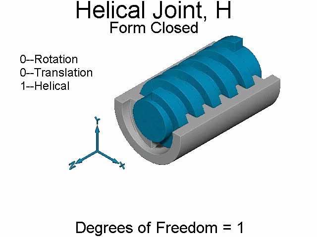
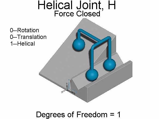
4 graphic image that is suitable to be used on the World Wide Web and many other computer programs. Kinematic Pairs The following 12 figures show the kinematic joints that were modeled using the Solidworks 99 solid modeler. Each figure was rendered using Photoworks 99 and shown in the JPG format. The axis systems have been removed from the pictures for better viewing of the kinematic pair models. A revolute joint model is shown in figure 1 given below. Figure 1(a) shows the form-closed version of the revolute joint and Fig. 1(b) shows the force-closed revolute joint. Counting the number of contact points of the force-closed model shows there are five contact points. Three of the contact points are between the pyramid that is recessed in the fixed rigid body and the sphere of the moving body. The other two contact points are between the spheres of the moving body and the flat surface of the fixed rigid body. Using equation (2), it can be shown that the forceclosed revolute joint has one degree of freedom. Knee and elbow joints of the human body are sometimes modeled as a revolute joint for simplicity. Fig. 1 Revolute Joint, R DOF = 1 Figure 2 shows the form-closed and force-closed models of the prism joint. The prism joint can only translate along one axis and therefore has one degree of freedom. The capital letter P is the given symbol for the prism joint. Fig. 2 Prism Joint, P DOF = 1 A helical joint is shown in figure 3. It is different from the revolute and prism joint that it appears to have two degrees of freedom, one rotation and one translation. The reason the helical joint is considered to have one degree of freedom is that the rotation and translation are coupled; Page


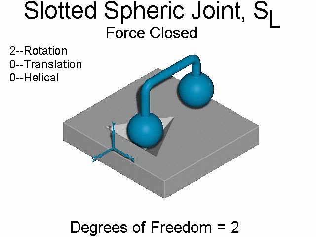
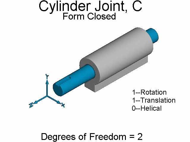
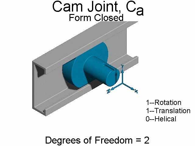
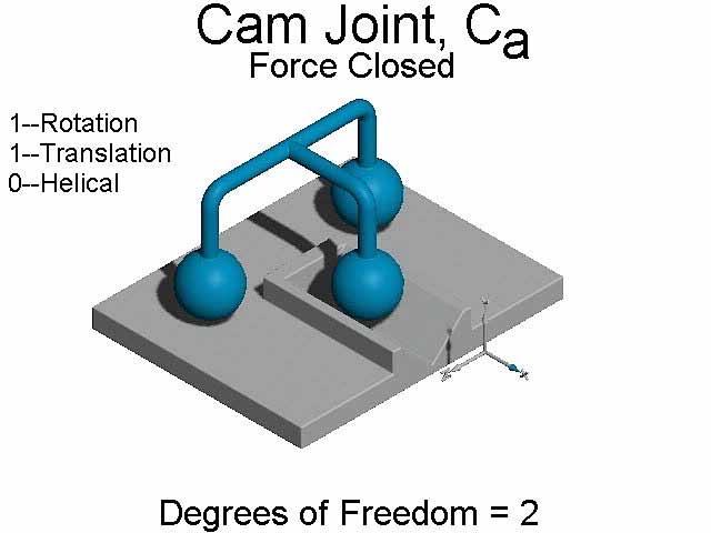
5 one cannot exist with out the other. For a given amount of rotation, the moving body will translate a fixed amount. A nut and bolt is a good example of a helical joint. The capital letter H is the symbol used for the helical joint. Fig. 3 Helical Joint, H DOF = 1 The first of the class II kinematic pairs is the slotted spheric joint shown in figure 4. The slotted spheric joint has two degrees of freedom. The degrees of freedom consist of two rotations. The symbol used for the slotted spheric joint is S L. Fig. 4 Slotted Spheric Joint, S L DOF = 2 A cylinder joint is shown in Figure 5. It has two degrees of freedom, one rotation and one translation. Unlike the helical joint, the rotation and translation in the cylinder joint are independent of one another. For a kinematic joint to be called a cylinder joint, both the rotation and translation must occur upon the same axis. The capital letter C is used as the symbol for the cylinder joint. Fig. 5 Cylinder Joint, C DOF = 2 Figure 6 illustrates a cam joint. Like the cylinder joint, the cam joint has two degrees of freedom, one rotation, and one translation. Unlike the cylinder joint, the cam joint s rotation and translation occur upon different axis. The symbol for the cam joint is C a. Page


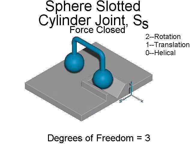
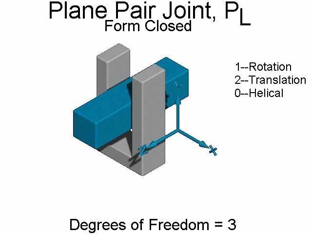
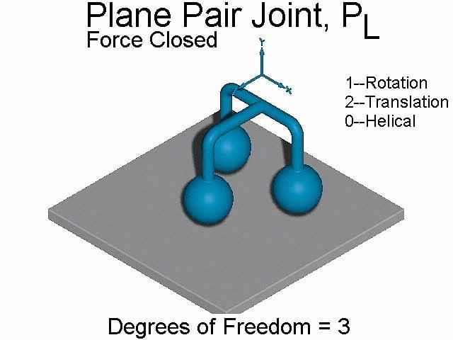
6 Fig. 6 Cam Joint, C a DOF = 2 The spheric pair joint shown in Figure 7 is a class III kinematic pair. The spheric pair joint has three rotations, one about each of its principle axis directions. For biomedical joints, the hip joint is modeled as a spheric pair. The spheric pair is also known as a ball and socket joint. The capital letter S is used as the symbol for the spheric pair joint. Fig. 7 Spheric Pair Joint, S DOF = 3 The sphere slotted cylinder pair has two rotations and one translation. Returning to equation 2, one can see that the sphere slotted cylinder has 3 degrees of freedom. The contact points are one between the flat plane of the fixed rigid body and the sphere of the moving body and two contact points exist between the v-groove in the fixed body and the sphere of the moving body. The symbol S S is given to the sphere slotted cylinder joint. The sphere slotted cylinder is shown in figure 8. Fig. 8 Sphere Slotted Cylinder Joint, S S DOF = 3 The two translations and the one rotation make the plane pair joint a class III kinematic pair. The symbol for the plane pair joint is P L. Using the Reuleaux classification system, the plane pair joint is classified as a lower kinematic pair. Viewing of the form-closed model shows that Page


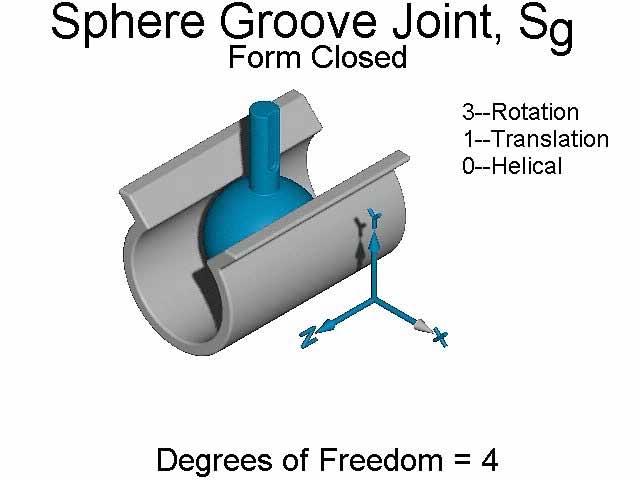
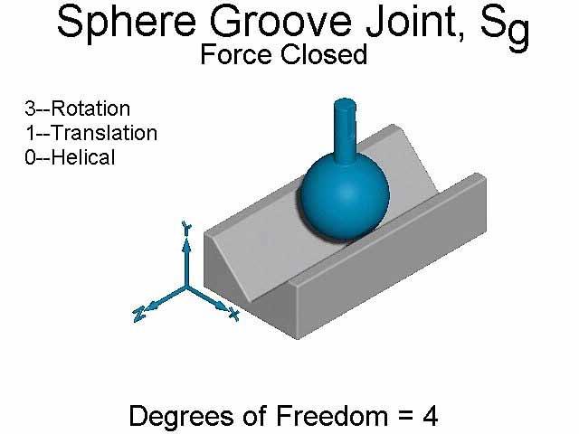
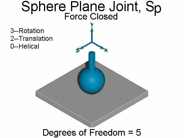
7 the surfaces of the moving body are in contact with the surface of the fixed body. Figure 9 illustrates the plane pair joint. Fig. 9 Plane Pair Joint, P L DOF = 3 The first kinematic pair in the class IV classification is the sphere groove joint. Similar to the sphere slotted cylinder joint, the sphere groove permits 3 rotations and one translation. S g is the symbol for the sphere groove joint. The sphere groove joint is shown in figure 10. Fig. 10 Sphere Groove Joint, S g DOF = 4 The cylinder plane pair is pictured in Figure 11. Using equation (2) and counting the two point contacts between the flat plane of the fixed rigid body and the two spheres of the moving body, it can be shown that the cylinder plane has four degrees of freedom. Viewing the form-closed model, it can be shown that the cylinder plane pair is a higher kinematic pair based on the Reuleaux classification system. There exists only a line contact between the cylinder of the moving body and the surface of the fixed rigid body. The symbol given to the cylinder plane pair is C p. Fig. 11 Cylinder Plane Pair Joint, C P DOF = 4 A class V kinematic pair is the sphere-plane joint. An example of a sphere plane joint is a ball on a flat table. The ball can perform three rotations, one about each of its principle axis Page

8 directions and two translations along the surface of the table. The sphere plane joint symbol is S P. Figure 12 shows the form-closed and force-closed models of a sphere-plane joint. Animation of Kinematic Pairs Fig. 12 Sphere Plane Joint, S P DOF = 5 To animate each model, animating capabilities of Solidworks 99 software were used 6. Each degree of freedom for every model was simulated using the software and saved as a Windows AVI movie. An AVI movie is a combination of still pictures with small delays between each picture to simulate animation. For a joint with multiple degrees of freedom, each degree of freedom was animated separately to help identify each movement. During the filming of each degree of freedom, further constraints were added to each assembly to insure that only one degree of freedom would be produced for that segment of film. The movies of each individual motion were then combined to make one movie that showed each degree of freedom in turn. The program used to combine the individual AVI files was ImageForge by CursurArts 7. Kinematic names and symbols were then added to the AVI files using ImageForge. Additional information about each kinematic pair, number of degrees of freedom, form-closed or forceclosed and the magnitude and type of each movement the kinematic pair exhibited, were added into the AVI movies. Summary Through the use of commercially available computer programs, solid models and animation of kinematic pairs were developed and the complex motions of kinematic pairs are presented. The Windows AVI files are created that can be placed on the World Wide Web for viewing or brought to the classroom through the use of multimedia presentation equipment. Table 1 provides a summary of all kinematic pairs. It will serve a useful handout to students to review the classification, degrees of freedom, name, and symbol of many kinematic pairs. Table 2 shows screen captured pictures from the multimedia AVI movie files. Students, who are having trouble visualizing complex three-dimensional motion of kinematic pairs by description provided in textbooks, will find the animations significantly useful. Page
9 Bibliography 1. Soni, A.H., 1974, Mechanism Synthesis and Analysis, Robert E. Krieger Publiching Company, Florida. 2. Erdman, Arthur G., and Sandor, George N., 1997, Mechanism Design, Analysis and Synthesis, Volume 1, Third Edition, Prentice Hall, New Jersey. 3. Wilson, Charles E., and Sadler, J. Peter, 1993, Kinematics and Dynamics of Machinery, Second Edition, Harper Collins College Publishers, New York. 4. Solidworks, 1999, Solidworks 99 User s Guide, Solidworks Corporation, Massachusetts. 5. Lightworks Design Limited, 1999, Photoworks Help, Lightworks Design Limited., United Kingdom. 6. Immersive Design, Inc., 1999, Solidworks Animator Help Topics, Immersive Design, Inc. Massachesett. 7. ImageForge, 2000, ImageForge Help Topics, CursorArts Company, Oregon. SCOTT MICHAEL WHARTON Scott Wharton received his master s degree in Mechanical Engineering for the University of Texas at San Antonio in the December Before returning to graduate school, Scott worked for Exponent, Inc. in Houston as a laboratory technician and with C&S Metal Fabricators in Houston as the factory supervisor. Scott received his B.S. in Engineering Technology from Texas A&M University in May Dr. YESH P. SINGH Yesh P. Singh is an Associate Professor of Mechanical Engineering at the University of Texas at San Antonio (UTSA). He also serves as Chair of ME Graduate Program and Director of the Engineering Machine Shop. He joined Mechanical Engineering at UTSA in September 1985 after 23 years of broad-based hands-on Mechanical Design experience in industries in USA, formal USSR, and India. He was elected to ASME Fellow grade in Page


10 Class Degrees of Freedom Name and Symbol KINEMATIC PAIRS Table 1 Diagram I 1 Revolute R Prism P R P H Form- Helical H R P H Force- II 2 Slotted Spheric - S L Cylinder C S L C C a Form- Cam - C a Force- S L C C a III 3 Spheric Pair S Sphere Slotted Cylinder - S S S S S P L Form- Plane Pair - P L Force- S S S P L Sphere Groove - S g Form- IV 4 Cylinder Plane Pair - C P S g C P Force- S g C P V 5 Sphere Plane - S P S P S P Form- Force- Page


11 KINEMATIC PAIRS MULTIMEDIA MOVIE SCREEN CAPTURES Table 2 Page


12 KINEMATIC PAIRS MULTIMEDIA MOVIE SCREEN CAPTURES Table 2 Continued Page
Modelling of mechanical system CREATING OF KINEMATIC CHAINS
 Modelling of mechanical system CREATING OF KINEMATIC CHAINS Mechanism Definitions 1. a system or structure of moving parts that performs some function 2. is each system reciprocally joined moveable bodies
SolidWorks Assembly Files. Assemblies Mobility. The Mating Game Mating features. Mechanical Mates Relative rotation about axes
 Assemblies Mobility SolidWorks Assembly Files An assembly file is a collection of parts The first part brought into an assembly file is fixed Other parts are constrained relative to that part (or other
Analytical and Applied Kinematics
 Analytical and Applied Kinematics Vito Moreno moreno@engr.uconn.edu 860-614-2365 (cell) http://www.engr.uconn.edu/~moreno Office EB1, hours Thursdays 10:00 to 5:00 1 This course introduces a unified and
Kinematics Fundamentals CREATING OF KINEMATIC CHAINS
 Kinematics Fundamentals CREATING OF KINEMATIC CHAINS Mechanism Definitions 1. a system or structure of moving parts that performs some function 2. is each system reciprocally joined moveable bodies the
Solving the Kinematics of Planar Mechanisms. Jassim Alhor
 Solving the Kinematics of Planar Mechanisms Jassim Alhor Table of Contents 1.0 Introduction 3 2.0 Methodology 3 2.1 Modeling in the Complex Plane 4 2.2 Writing the Loop Closure Equations 4 2.3 Solving
Theory of Machines Course # 1
 Theory of Machines Course # 1 Ayman Nada Assistant Professor Jazan University, KSA. arobust@tedata.net.eg March 29, 2010 ii Sucess is not coming in a day 1 2 Chapter 1 INTRODUCTION 1.1 Introduction Mechanisms
SAMPLE STUDY MATERIAL. Mechanical Engineering. Postal Correspondence Course. Theory of Machines. GATE, IES & PSUs
 TOM - ME GATE, IES, PSU 1 SAMPLE STUDY MATERIAL Mechanical Engineering ME Postal Correspondence Course Theory of Machines GATE, IES & PSUs TOM - ME GATE, IES, PSU 2 C O N T E N T TOPIC 1. MACHANISMS AND
ME 321 Kinematics and Dynamics of Machines
 .0 INTRODUCTION ME Kinematics and Dynamics of Machines All Text References in these notes are for: Mechanism Design: Analysis and Synthesis, Volume, Fourth Edition, Erdman, Sandor and Kota, Prentice-Hall,
Chapter 1 Introduction
 Chapter 1 Introduction Generally all considerations in the force analysis of mechanisms, whether static or dynamic, the links are assumed to be rigid. The complexity of the mathematical analysis of mechanisms
WEEKS 1-2 MECHANISMS
 References WEEKS 1-2 MECHANISMS (METU, Department of Mechanical Engineering) Text Book: Mechanisms Web Page: http://www.me.metu.edu.tr/people/eres/me301/in dex.ht Analitik Çözümlü Örneklerle Mekanizma
KINEMATICS OF MACHINES. Dr.V.SUNDARESWARAN PROFESSOR OF MECHANICAL ENGG. COLLEGE OF ENGINEERING, GUINDY ANNA UNIVERSITY CHENNAI
 KINEMATICS OF MACHINES Dr.V.SUNDARESWARAN PROFESSOR OF MECHANICAL ENGG. COLLEGE OF ENGINEERING, GUINDY ANNA UNIVERSITY CHENNAI 600 025 MECHANICS Science dealing with motion DIVISIONS OF MECHANICS Statics
CALCULATING TRANSFORMATIONS OF KINEMATIC CHAINS USING HOMOGENEOUS COORDINATES
 CALCULATING TRANSFORMATIONS OF KINEMATIC CHAINS USING HOMOGENEOUS COORDINATES YINGYING REN Abstract. In this paper, the applications of homogeneous coordinates are discussed to obtain an efficient model
Kinematic Design Principles
 Kinematic Design Principles BJ Furman 24SEP97 Introduction Machines and instruments are made up of elements that are suitably arranged and many of which that are movably connected. Two parts that are in
SYNTHESIS OF PLANAR MECHANISMS FOR PICK AND PLACE TASKS WITH GUIDING LOCATIONS
 Proceedings of the ASME 2013 International Design Engineering Technical Conferences and Computers and Information in Engineering Conference IDETC/CIE 2013 August 4-7, 2013, Portland, Oregon, USA DETC2013-12021
Analysis of a 4 Bar Crank-Rocker Mechanism Using COSMOSMotion
 Analysis of a 4 Bar Crank-Rocker Mechanism Using COSMOSMotion ME345: Modeling and Simulation Professor Frank Fisher Stevens Institute of Technology Last updated: June 29th, 2009 Table of Contents 1. Introduction
IMECE FUNCTIONAL INTERFACE-BASED ASSEMBLY MODELING
 Proceedings of IMECE2005 2005 ASME International Mechanical Engineering Congress and Exposition November 5-11, 2005, Orlando, Florida USA IMECE2005-79945 FUNCTIONAL INTERFACE-BASED ASSEMBLY MODELING James
Chapter 4. Mechanism Design and Analysis
 Chapter 4. Mechanism Design and Analysis All mechanical devices containing moving parts are composed of some type of mechanism. A mechanism is a group of links interacting with each other through joints
September 20, Chapter 5. Simple Mechanisms. Mohammad Suliman Abuhaiba, Ph.D., PE
 Chapter 5 Simple Mechanisms 1 Mohammad Suliman Abuhaiba, Ph.D., PE 2 Assignment #1 All questions at the end of chapter 1 st Exam: Saturday 29/9/2018 3 Kinematic Link or Element kinematic link (link) or
Mechanism Simulation With Working Model
 Mechanism Simulation With Working Model Shih-Liang Wang Department of Mechanical Engineering North Carolina A&T State University Greensboro, NC 27411 Introduction Kinematics is a study of motion and force
MAE 342 Dynamics of Machines. Types of Mechanisms. type and mobility
 MAE 342 Dynamics of Machines Types of Mechanisms Classification of Mechanisms by type and mobility MAE 342 Dynamics of Machines 2 Planar, Spherical and Spatial Mechanisms Planar Mechanisms: all points
A rigid body free to move in a reference frame will, in the general case, have complex motion, which is simultaneously a combination of rotation and
 050389 - Analtical Elements of Mechanisms Introduction. Degrees of Freedom he number of degrees of freedom (DOF) of a sstem is equal to the number of independent parameters (measurements) that are needed
Lesson 1: Introduction to Pro/MECHANICA Motion
 Lesson 1: Introduction to Pro/MECHANICA Motion 1.1 Overview of the Lesson The purpose of this lesson is to provide you with a brief overview of Pro/MECHANICA Motion, also called Motion in this book. Motion
Animations in Creo 3.0
 Animations in Creo 3.0 ME170 Part I. Introduction & Outline Animations provide useful demonstrations and analyses of a mechanism's motion. This document will present two ways to create a motion animation
DETC2000/MECH KINEMATIC SYNTHESIS OF BINARY ACTUATED MECHANISMS FOR RIGID BODY GUIDANCE
 Proceedings of DETC ASME International Design Engineering Technical Conferences and Computers and Information in Engineering Conference Baltimore, Maryland, September -3, DETC/MECH-7 KINEMATIC SYNTHESIS
Mechanism and Robot Kinematics, Part I: Algebraic Foundations
 Mechanism and Robot Kinematics, Part I: Algebraic Foundations Charles Wampler General Motors R&D Center In collaboration with Andrew Sommese University of Notre Dame Overview Why kinematics is (mostly)
VD - Design Validation
 Coordinating unit: Teaching unit: Academic year: Degree: ECTS credits: 2017 295 - EEBE - Barcelona East School of Engineering 717 - EGE - Department of Engineering Presentation BACHELOR'S DEGREE IN ELECTRICAL
Visualizing Regions of Integration in 2-D Cartesian Coordinates
 Classroom Tips and Techniques: Visualizing Regions of Integration Robert J. Lopez Emeritus Professor of Mathematics and Maple Fellow Maplesoft Introduction Five of the new task templates in Maple 14 are
2.007 Design and Manufacturing I Spring 2009
 MIT OpenCourseWare http://ocw.mit.edu 2.007 Design and Manufacturing I Spring 2009 For information about citing these materials or our Terms of Use, visit: http://ocw.mit.edu/terms. 2.007 Design and Manufacturing
Kinematic Synthesis. October 6, 2015 Mark Plecnik
 Kinematic Synthesis October 6, 2015 Mark Plecnik Classifying Mechanisms Several dichotomies Serial and Parallel Few DOFS and Many DOFS Planar/Spherical and Spatial Rigid and Compliant Mechanism Trade-offs
Spatial R-C-C-R Mechanism for a Single DOF Gripper
 NaCoMM-2009-ASMRL28 Spatial R-C-C-R Mechanism for a Single DOF Gripper Rajeev Lochana C.G * Mechanical Engineering Department Indian Institute of Technology Delhi, New Delhi, India * Email: rajeev@ar-cad.com
Spring Assembly. in the Begin Assembly Property. on the Standard toolbar and click Add-Ins.
 Chapter 2 Spring Assembly A. Create New Assembly. Step 1. Click File Menu > New, click Assembly and OK. Step 2. Click Cancel Manager. in the Begin Assembly Property B. Enable Toolbox Browser. Step 1. If
Kinematic and Dynamic Analysis of Stephenson Six Bar Mechanism Using HyperWorks
 Kinematic and Dynamic Analysis of Stephenson Six Bar Mechanism Using HyperWorks Kailash Chaudhary Phd Scholar Malaviya National Institute of Technology,Jaipur JLN Marg, Jaipur - 302 017, India Dr. Himanshu
ADJUSTABLE GEOMETRIC CONSTRAINTS 2001 MIT PSDAM AND PERG LABS
 ADJUSTABLE GEOMETRIC CONSTRAINTS Why adjust kinematic couplings? KC Repeatability is orders of magnitude better than accuracy Accuracy = f ( manufacture and assemble ) Kinematic Coupling Accuracy Adjusted
Using Classical Mechanism Concepts to Motivate Modern Mechanism Analysis and Synthesis Methods
 Using Classical Mechanism Concepts to Motivate Modern Mechanism Analysis and Synthesis Methods Robert LeMaster, Ph.D. 1 Abstract This paper describes a methodology by which fundamental concepts in the
Roswell Independent School District Grade Level Targets Summer 2010
 1 NM Standards Children s Progress Core Standards Target: Possesses a working knowledge of the base ten number system, including ones and tens. Q1 Counts, sketches and represents some numbers. Q2 Counts,
Principles of Kinematic Constraint
 Principles of Kinematic Constraint For holding a body (rigid thing) with the highest precision, we require: Full 6 DoF constraint If 6 DoFs not fully constrained, then one is loose. No overconstraint Any
Kinematics of Machines. Brown Hills College of Engineering & Technology
 Introduction: mechanism and machines, kinematic links, kinematic pairs, kinematic chains, plane and space mechanism, kinematic inversion, equivalent linkages, four link planar mechanisms, mobility and
[Hasan*, 4.(7): July, 2015] ISSN: (I2OR), Publication Impact Factor: 3.785
![[Hasan*, 4.(7): July, 2015] ISSN: (I2OR), Publication Impact Factor: 3.785](/thumbs/86/93816785.jpg "[Hasan*, 4.(7): July, 2015] ISSN: (I2OR), Publication Impact Factor: 3.785") IJESRT INTERNATIONAL JOURNAL OF ENGINEERING SCIENCES & RESEARCH TECHNOLOGY STUDY OF EPICYCLIC GEAR TRAINS USING GRAPH THEORY Dr. Ali Hasan* * Mech. Engg.Deptt.,Jamia Millia Islamia, New Delhi. ABSTRACT
IJESRT INTERNATIONAL JOURNAL OF ENGINEERING SCIENCES & RESEARCH TECHNOLOGY STUDY OF EPICYCLIC GEAR TRAINS USING GRAPH THEORY Dr. Ali Hasan* * Mech. Engg.Deptt.,Jamia Millia Islamia, New Delhi. ABSTRACT
Anoka Hennepin K-12 Curriculum plan
 Anoka Hennepin K-12 Curriculum plan Department: Elementary Math Unit Title: Packages and Polygons (Blue Book, Geo and Measurement) Triangles and Beyond (Blue Book, Geo and Measurement) Everyday Math: Volume
DESIGN AND ANALYSIS OF WEIGHT SHIFT STEERING MECHANISM BASED ON FOUR BAR MECHANISM
 International Journal of Mechanical Engineering and Technology (IJMET) Volume 8, Issue 12, December 2017, pp. 417 424, Article ID: IJMET_08_12_041 Available online at http://www.iaeme.com/ijmet/issues.asp?jtype=ijmet&vtype=8&itype=12
Kinematics - Introduction. Robotics. Kinematics - Introduction. Vladimír Smutný
 Kinematics - Introduction Robotics Kinematics - Introduction Vladimír Smutný Center for Machine Perception Czech Institute for Informatics, Robotics, and Cybernetics (CIIRC) Czech Technical University
Connection Elements and Connection Library
 Connection Elements and Connection Library Lecture 2 L2.2 Overview Introduction Defining Connector Elements Understanding Connector Sections Understanding Connection Types Understanding Connector Local
Attach to this tutorial, there are some drawings to create the CAD models with Solid Works.
 Modeling and Simulation Tutorial 1. (Slider Mechanism) Objective: To Create Slider Mechanism Elements to Use: SolidWorks Cosmos Motion Dynamics Books Description: This tutorial explains how to set up different
11.9 Three dimensional Coordinates
 11.9 Three dimensional Coordinates Apr 1 10:06 AM 1 A Three Dimensional Coordinate System Dec 9 5:26 PM 2 With an ordered triple (x, y, z) Dec 9 5:26 PM 3 x axis y axis z axis Dec 9 5:26 PM 4 Dec 9 5:26
About the Author. Acknowledgements
 About the Author Dr. Paul Kurowski obtained his MSc and PhD in Applied Mechanics from Warsaw Technical University. He completed postdoctoral work at Kyoto University. Dr. Kurowski is an Assistant Professor
11. Kinematic models of contact Mechanics of Manipulation
 11. Kinematic models of contact Mechanics of Manipulation Matt Mason matt.mason@cs.cmu.edu http://www.cs.cmu.edu/~mason Carnegie Mellon Lecture 11. Mechanics of Manipulation p.1 Lecture 11. Kinematic models
KINEMATICS OF AN OVERCONSTRAINED MECHANISM IN PRACTICE
 KINEMTICS OF N OVERCONSTRINED MECHNISM IN PRCTICE Vandan Kamlakar Gundale* bstract: In 1939 Paul Schatz, a Swiss anthroposophist and geometrician had invented a mechanism which with few links generates
Human Motion. Session Speaker Dr. M. D. Deshpande. AML2506 Biomechanics and Flow Simulation PEMP-AML2506
 AML2506 Biomechanics and Flow Simulation Day 02A Kinematic Concepts for Analyzing Human Motion Session Speaker Dr. M. D. Deshpande 1 Session Objectives At the end of this session the delegate would have
Lecture 30 of 41. Animation 3 of 3: Inverse Kinematics Control & Ragdoll Physics
 Animation 3 of 3: Inverse Kinematics Control & Ragdoll Physics William H. Hsu Department of Computing and Information Sciences, KSU KSOL course pages: http://bit.ly/hgvxlh / http://bit.ly/evizre Public
Lecture 30 of 41. Animation 3 of 3: Inverse Kinematics Control & Ragdoll Physics
 Animation 3 of 3: Inverse Kinematics Control & Ragdoll Physics William H. Hsu Department of Computing and Information Sciences, KSU KSOL course pages: http://bit.ly/hgvxlh / http://bit.ly/evizre Public
Chapter 19 Assembly Modeling with the TETRIX by Pitsco Building System Autodesk Inventor
 Tools for Design Using AutoCAD and Autodesk Inventor 19-1 Chapter 19 Assembly Modeling with the TETRIX by Pitsco Building System Autodesk Inventor Create and Use Subassemblies in Assemblies Creating an
Using Computer Graphics for Descriptive Geometry-style Problems in a Freshman Graphics Course
 Session 2238 Using Computer Graphics for Descriptive Geometry-style Problems in a Freshman Graphics Course Dennis R. Stevenson, P. E. University of Wisconsin-Parkside Abstract This is a report on a project
ME 3222 Design & Manufacturing II. Creating and Animating a Slider-Crank in Creo Elements (Version 2.0)
") ME 3222 Design & Manufacturing II Creating and Animating a Slider-Crank in Creo Elements (Version 2.0) Tom Chase February 18, 2016 Overview This document explains how to create a mechanism and animate
ME 3222 Design & Manufacturing II Creating and Animating a Slider-Crank in Creo Elements (Version 2.0) Tom Chase February 18, 2016 Overview This document explains how to create a mechanism and animate
Vibration Analysis with SOLIDWORKS Simulation and SOLIDWORKS. Before you start 7
 i Table of contents Before you start 7 Notes on hands-on exercises and functionality of Simulation Prerequisites Selected terminology 1: Introduction to vibration analysis 10 Differences between a mechanism
Interactive Computer Graphics
 Interactive Computer Graphics Lecture 18 Kinematics and Animation Interactive Graphics Lecture 18: Slide 1 Animation of 3D models In the early days physical models were altered frame by frame to create
Kinematics. Kinematics analyzes the geometry of a manipulator, robot or machine motion. The essential concept is a position.
 Kinematics Kinematics analyzes the geometry of a manipulator, robot or machine motion. The essential concept is a position. 1/31 Statics deals with the forces and moments which are aplied on the mechanism
Industrial Robots : Manipulators, Kinematics, Dynamics
 Industrial Robots : Manipulators, Kinematics, Dynamics z z y x z y x z y y x x In Industrial terms Robot Manipulators The study of robot manipulators involves dealing with the positions and orientations
Application Notes for Team Hydrostatic Pad Bearings
 Application Notes for Team Hydrostatic Pad Bearings THESE COMMODITIES, TECHNOLOGY, OR SOFTWARE WERE EXPORTED FROM THE UNITED STATES IN ACCORDANCE WITH THE EXPORT ADMINISTRATION REGULATIONS. DIVERSION CONTRARY
Module 2 Review. Assemblies and Rendering. Why Use Assemblies. Assemblies - Key Concepts. Sketch Planes Sketched Features.
 Module 2 Review Assemblies and Rendering EF 101 Modules 3.1, 3.2 Sketch Planes Sketched Features Extrude, Revolve Placed Features Hole, Fillet, Chamfer, Shell, Rect. Pattern Drawing Views Base, Ortho,
The School District of Palm Beach County Kindergarten Mathematics Scope st Trimester
 1 st Trimester Counting and Cardinality (CC) Know number names and the count sequence. CC.1.3 CC.2.4 CC.2.5 Read and write numerals from 0 to 20. Represent a number of objects with a written numeral 0-20
Evaluation of Structural Geometry for Mini Milling Machine by Boolean-algebra technique
 5 th International & 26 th All India Manufacturing Technology, Design and Research Conference (AIMTDR 2014) December 12 th 14 th, 2014, IIT Guwahati, Assam, India Evaluation of Structural Geometry for
Model Library Mechanics
 Model Library Mechanics Using the libraries Mechanics 1D (Linear), Mechanics 1D (Rotary), Modal System incl. ANSYS interface, and MBS Mechanics (3D) incl. CAD import via STL and the additional options
Jane Li. Assistant Professor Mechanical Engineering Department, Robotic Engineering Program Worcester Polytechnic Institute
 Jane Li Assistant Professor Mechanical Engineering Department, Robotic Engineering Program Worcester Polytechnic Institute We know how to describe the transformation of a single rigid object w.r.t. a single
Assembly Modeling Constraints. ENGR 1182 SolidWorks 05
 Assembly Modeling Constraints ENGR 1182 SolidWorks 05 Today s Objectives Creating assemblies by constraining 3D parts together Movement and Location dictated by Constraints SW05 Activity SW05 Application
Simulation and Modeling of 6-DOF Robot Manipulator Using Matlab Software
 Simulation and Modeling of 6-DOF Robot Manipulator Using Matlab Software 1 Thavamani.P, 2 Ramesh.K, 3 Sundari.B 1 M.E Scholar, Applied Electronics, JCET, Dharmapuri, Tamilnadu, India 2 Associate Professor,
What Is SimMechanics?
 SimMechanics 1 simulink What Is Simulink? Simulink is a tool for simulating dynamic systems with a graphical interface specially developed for this purpose. Physical Modeling runs within the Simulink environment
SOLIDWORKS: Lesson 1 - Basics and Modeling. UCF Engineering
 SOLIDWORKS: Lesson 1 - Basics and Modeling Fundamentals UCF Engineering SolidWorks SolidWorks is a 3D solid modeling package which allows users to develop full solid models in a simulated environment for
Algebra and Trigonometry, Second Edition By James Stewart, Lothar Redlin, & Saleem Watson 2007, Thompson Brooks / Cole
 GEOMETRY/TRIGONOMETRY Textbooks: Geometry, Integrated Mathematics, Second Edition, The University of Chicago School mathematics Project (UCSMP), Prentice Hall Algebra and Trigonometry, Second Edition By
ALGEBRA IIA/GEOMETRY FORM II
 ALGEBRA IIA/GEOMETRY FORM II Textbooks: Geometry, Integrated Mathematics, Second Edition, The University of Chicago School mathematics Project (UCSMP), Prentice Hall, Algebra and Trigonometry, Second Edition
Session #5 2D Mechanisms: Mobility, Kinematic Analysis & Synthesis
 Session #5 2D Mechanisms: Mobility, Kinematic Analysis & Synthesis Courtesy of Design Simulation Technologies, Inc. Used with permission. Dan Frey Today s Agenda Collect assignment #2 Begin mechanisms
Rebecca R. Romatoski. B.S. Mechanical Engineering Massachusetts Institute of Technology, 2006
 Robotic End Effecter for the Introduction to Robotics Laboratory Robotic Arms by Rebecca R. Romatoski B.S. Mechanical Engineering Massachusetts Institute of Technology, 2006 SUBMITTED TO THE DEPARTMENT
3 Identify shapes as two-dimensional (lying in a plane, flat ) or three-dimensional ( solid ).
 or three-dimensional ( solid ).") Geometry Kindergarten Identify and describe shapes (squares, circles, triangles, rectangles, hexagons, cubes, cones, cylinders, and spheres). 1 Describe objects in the environment using names of shapes,
Geometry Kindergarten Identify and describe shapes (squares, circles, triangles, rectangles, hexagons, cubes, cones, cylinders, and spheres). 1 Describe objects in the environment using names of shapes,
MACHINE THEORY Bachelor in Mechanical Engineering INTRODUCTION TO MACHINE DESIGN
 MACHINE THEORY Bachelor in Mechanical Engineering INTRODUCTION TO MACHINE DESIGN Ignacio Valiente Blanco José Luis Pérez Díaz David Mauricio Alba Lucero Efrén Díez Jiménez Timm Lauri Berit Sanders Machine
Geometry. Talk About It. More Ideas. Formative Assessment. Have children try the following problem.
 K.G.2 K.G.3 K.G.4 176 10 Objective Common Core State Standards Cubes and Spheres In mathematics, three-dimensional figures are also called solids. If something is three-dimensional, it is considered to
Instructional Alignment Chart
 CLUSTER HEADING: STANDARD: N/A CLUSTER HEADING: Identify and describe shapes (squares, circles, triangles, rectangles, hexagons, cubes, cones, cylinders, and spheres). STANDARD: K.G.3 Identify shapes as
Robotics Configuration of Robot Manipulators
 Robotics Configuration of Robot Manipulators Configurations for Robot Manipulators Cartesian Spherical Cylindrical Articulated Parallel Kinematics I. Cartesian Geometry Also called rectangular, rectilinear,
PPGEE Robot Dynamics I
 PPGEE Electrical Engineering Graduate Program UFMG April 2014 1 Introduction to Robotics 2 3 4 5 What is a Robot? According to RIA Robot Institute of America A Robot is a reprogrammable multifunctional
SolidWorks Motion Study Tutorial
 SolidWorks Motion Study Tutorial By: Mohamed Hakeem Mohamed Nizar Mechanical Engineering Student- May 2015 South Dakota School of Mines & Technology August 2013 Getting Started This tutorial is for you
Introduction To Robotics (Kinematics, Dynamics, and Design)
") Introduction To Robotics (Kinematics, Dynamics, and Design) SESSION # 5: Concepts & Defenitions Ali Meghdari, Professor School of Mechanical Engineering Sharif University of Technology Tehran, IRAN 11365-9567
Introduction To Robotics (Kinematics, Dynamics, and Design) SESSION # 5: Concepts & Defenitions Ali Meghdari, Professor School of Mechanical Engineering Sharif University of Technology Tehran, IRAN 11365-9567
Transformations Reflections, and Rotations
 Grade level: 9-12 Subject: mathematics Time required: 30 minutes Transformations Reflections, and Rotations by Lynne B. Uebelhoer Activity overview This activity is designed to be used in a middle-school
DESIGN OF ONE DEGREE OF FREEDOM CLOSED LOOP SPATIAL CHAINS USING NON-CIRCULAR GEARS
 DESIGN OF ONE DEGREE OF FREEDOM CLOSED LOOP SPATIAL CHAINS USING NON-CIRCULAR GEARS By MANDAR SHRIKANT HARSHE A THESIS PRESENTED TO THE GRADUATE SCHOOL OF THE UNIVERSITY OF FLORIDA IN PARTIAL FULFILLMENT
Feature-Based Modeling and Optional Advanced Modeling. ENGR 1182 SolidWorks 05
 Feature-Based Modeling and Optional Advanced Modeling ENGR 1182 SolidWorks 05 Today s Objectives Feature-Based Modeling (comprised of 2 sections as shown below) 1. Breaking it down into features Creating
Mr. Kelly s Geometry Syllabus
 Geometry Syllabus The following is a general description and an outline of the topics covered in a full year of geometry. The outline is broken into parts A and B to correspond to our trimesters. Steven
CHAPTER 1 : KINEMATICS
 KINEMATICS : It relates to the study of the relative motion between the parts of a machine. Let us consider a reciprocating engine, in this the piston is made to reciprocate in the cylinderdue to the applied
AUTOMATIC COLLISION DETECTION FOR ASSEMBLY SEQUENCE PLANNING USING A THREE-DIMENSIONAL SOLID MODEL
 Journal of Advanced Manufacturing Systems Vol. 10, No. 2 (2011) 277 291 c World Scientific Publishing Company DOI: 10.1142/S021968671100220X AUTOMATIC COLLISION DETECTION FOR ASSEMBLY SEQUENCE PLANNING
Methodology to Determine Counterweights for Passive Balancing of a 3-R Orientation Sensing Mechanism using Hanging Method
 Methodology to Determine Counterweights for Passive Balancing of a 3-R Orientation Sensing Mechanism using Hanging Method Shasa A. Antao, Vishnu S. Nair and Rajeevlochana G. Chittawadigi Department of
Unit Maps: Grade 2 Math
 Place Value and Comparing Numbers 2.3 Place value. The student understands how to represent and compare whole numbers, the relative position and magnitude of whole numbers, and relationships within the
SolidWorks. An Overview of SolidWorks and Its Associated Analysis Programs
 An Overview of SolidWorks and Its Associated Analysis Programs prepared by Prof. D. Xue University of Calgary SolidWorks - a solid modeling CAD tool. COSMOSWorks - a design analysis system fully integrated
Lesson 4: Assembly Basics
 4 Lesson 4: Assembly Basics Goals of This Lesson Understand how parts and assemblies are related. Create and modify the part Tutor2 and create the Tutor assembly. Tutor1 Tutor2 Tutor assembly Before Beginning
Consolidation of Grade 6 EQAO Questions Geometry and Spatial Sense
 Consolidation of Grade 6 EQAO Questions Geometry and Spatial Sense SE2 Families of Schools Year GV1 GV2 GV3 Spring 2006 Spring 2007 Spring 2008 MC14 MC24 MC13 OR9 MC17 OR30 OR9 MC21 MC18 MC3 MC23 OR30
MEM30004A. AutoCAD Inventor Advanced Use CAD to create and display 3D models. MEM30004A Autodesk Inventor (Advanced)
") MEM30004A AutoCAD Inventor Advanced Use CAD to create and display 3D models. BlackLine Design Page 1 of 26 Table of Contents Conditions of Use:... 2 Unit Resource Manual... 2 Manufacturing Skills Australia
MEM30004A AutoCAD Inventor Advanced Use CAD to create and display 3D models. BlackLine Design Page 1 of 26 Table of Contents Conditions of Use:... 2 Unit Resource Manual... 2 Manufacturing Skills Australia
240AR059 - Geometric Fundamentals for Robot Design
 Coordinating unit: Teaching unit: Academic year: Degree: ECTS credits: 2018 240 - ETSEIB - Barcelona School of Industrial Engineering 707 - ESAII - Department of Automatic Control MASTER'S DEGREE IN AUTOMATIC
Rigid Dynamics Solution Methodology for 3-PSU Parallel Kinematic Manipulators
 Rigid Dynamics Solution Methodology for 3-PSU Parallel Kinematic Manipulators Arya B. Changela 1, Dr. Ramdevsinh Jhala 2, Chirag P. Kalariya 3 Keyur P. Hirpara 4 Assistant Professor, Department of Mechanical
An inverse kinematics approach to hexapod design and control
 An inverse kinematics approach to hexapod design and control Frank A. DeWitt IV Melles Griot, 55 Science Parkway, Rochester, NY 1460 phone +1 585 44-70; email mgoptics@idexcorp.com COPYRIGHT 009 Society
Rigging / Skinning. based on Taku Komura, Jehee Lee and Charles B.Own's slides
 Rigging / Skinning based on Taku Komura, Jehee Lee and Charles B.Own's slides Skeletal Animation Victoria 2 CSE 872 Dr. Charles B. Owen Advanced Computer Graphics Skinning http://www.youtube.com/watch?
ME Week 11 Create Joints Project
 One of the most important elements of dynamic simulation is setting up and verifying that proper joints are created. Joints are links between two rigid components that applies force from the first component
Kinematic Model Analysis of an 8-DOF Photographic Robot
 Kinematic Model Analysis of an 8-DOF Photographic Robot Xiaowei Xie, Xingang Miao, Su Wang and Feng Zhang Abstract The photographic robot studied in this chapter is an 8-DOF PRRPR-S type. In order to obtain
DETC SLIDER CRANKS AS COMPATIBILITY LINKAGES FOR PARAMETERIZING CENTER POINT CURVES
 Proceedings of the ASME 2009 International Design Engineering Technical Conferences & Computers and Information Proceedings in Engineering of IDETC/CIE Conference 2009 ASME 2009 International Design Engineering
Motion Simulation and Mechanism Design with SOLIDWORKS Motion 2017
 Motion Simulation and Mechanism Design with SOLIDWORKS Motion 2017 Kuang-Hua Chang Ph.D. SDC P U B L I C AT I O N S Better Textbooks. Lower Prices. www.sdcpublications.com Powered by TCPDF (www.tcpdf.org)
Introduction to Solid Modeling Parametric Modeling. Mechanical Engineering Dept.
 Introduction to Solid Modeling Parametric Modeling 1 Why draw 3D Models? 3D models are easier to interpret. Simulation under real-life conditions. Less expensive than building a physical model. 3D models