MODEL-BASED SOFTWARE DESIGN TOOLS FOR THE CELL PROCESSOR. Nicholas Stephen Lowell. Thesis. Submitted to the Faculty of the
|
|
|
- Octavia Sharp
- 6 years ago
- Views:
Transcription
1 MODEL-BASED SOFTWARE DESIGN TOOLS FOR THE CELL PROCESSOR By Nicholas Stephen Lowell Thesis Submitted to the Faculty of the Graduate School of Vanderbilt University in partial fulfillment of the requirements for the degree of MASTER OF SCIENCE in Electrical Engineering May, 2009 Nashville, Tennessee Approved: Professor Gabor Karsai Professor Sandeep Neema
2 To my ever caring, ever supportive, ever encouraging, ever humbling, ever faithful, and ever loving parents. ii
3 ACKNOWLEDGEMENTS This research was performed under the support of a Raytheon grant and Raytheon contact, Andrew M. Vandivort. I want to thank Dr. Sandeep Neema, Dr. Gabor Karsai, and the Institute for Software Integrated Systems (ISIS) for the wonderful support, guidance, and opportunity to further my education and experience at Vanderbilt University and as a part of ISIS. I also want to thank those professors at Lipscomb University who willingly went beyond the call of duty to teach me and prepare me for all of life s opportunities and challenges. Finally, I thank my friends and my family. They bring me joy and laughter, they exemplify faithfulness and love, and they believe in me even when I do not. iii
4 TABLE OF CONTENTS Page DEDICATION...ii ACKNOWLEDGEMENTS...iii LIST OF TABLES...vi LIST OF FIGURES...vii LIST OF ABBREVIATIONS...ix Chapter I. INTRODUCTION... 1 II. BACKGROUND... 3 III. CELL PROCESSOR... 8 PowerPC Processing Element... 9 Synergistic Processing Element Memory Flow Controller Element Interconnect Bus Sony PlayStation IV. SIGNAL PROCESSING PLATFORM Signal Processing Modeling Language Execution Platform Code Generator Interpreter Tool Chain V. AUTOMATIC TARGET RECOGNITION EXAMPLE Modeling Generating Code Interpreting Execution on PC Reconfigure for Cell Memory Consumption Algorithm Analysis iv
5 Replacing Cores for the Cell and Code Optimizations Execution on Cell VI. RESULTS VII. FUTURE WORK VIII. CONCLUSION Appendix A. META-MODEL OF SPML DATATYPING B. META-MODEL OF SPML CORE C. META-MODEL OF SPML ARCHITECTURE D. META-MODEL OF SPML APPLICATION DATAFLOW E. GENERATED WRAPPER CODE FOR CALCULATE_DISTANCE F. GENERATED DATA TYPE HEADER FILE G. GENERATED IX86 MAIN.C SYSTEM SOURCE FILE H. GENERATED IX86 SYSTEM MAKEFILE I. GENERATED PROCESS TABLE J. GENERATED CONFIGURATION FILE K. GENERATED CELL MAIN.C SYSTEM SOURCE FILE L. GENERATED CELL SYSTEM MAKEFILE M. GENERATED WRAPPER CODE FOR SPE-RUN CALCULATE_DISTANCE N. GENERATED SPE CODE FOR CALCULATE_DISTANCE O. GENERATED SPE MAKEFILE FOR CALCULATE_DISTANCE P. MODIFIED SPE CODE FOR MULT_DIFFT_CALC_MEAN_PSR REFERENCES v
6 LIST OF TABLES Table Page 1. Run Time and FLOP Count of Pipe Tasks FLOP Count for ATR Tasks Performance of ATR Breadown of Mult_TwoDIFFT_Calc_Mean_PSR on SPEs Mult_TwoDIFFT_Calc_Mean_PSR Run Times: XLC vs GCC Breakdown of Calculate_Distance on SPEs vi
7 LIST OF FIGURES Figure Page 1. Different Processor Architectures The Cell Broadband Engine Architecture Die of Cell Processor Execution Platform Managing Code SPP Tool Chain Defining CIMAGE Data Type AppDataflow Aspect for Calculate_Distance TypeAspect Aspect for Calculate_Distance Design of calc_distance_core ImplAspect Aspect for Calculate_Distance Design of Pipe Component for ATR Defined Hardware Types Model of ATR Application for HostPC Wrapper Code Generator SPP Tool Chain Control Panel ATR GUI Running on PC Structure of Merged Pipe in ATR AppDataflow Aspect for Mult_TwoDIFFT_Calc_Mean_PSR TypeAspect Aspect for Mult_TwoDIFFT_Calc_Mean_PSR vii
8 21. ImplAspect Aspect for Mult_TwoDIFFT_Calc_Mean_PSR Design of mult_difft_calc_mean_psr_core Defining ROI Data Type Model of ATR Application for Cell ATR GUI running on Cell ATR Timeline Benefits of Double Buffering ATR Timeline with Stream Depth of ATR Timeline with Stream Depth of viii
9 LIST OF ABBREVIATIONS API Application Programming Interface ATR Automatic Target Recognition CPU Central Processing Unit DCCF Distance Classifier Correlation Filter DMA Direct Memory Access DSML Domain-Specific Modeling Language DSP Digital Signal Processor EA Effective Address EIB Element Interconnect Bus FFT Fast Fourier Transform FLOP Floating-Point Operation FLOPS Floating-Point Operations Per Second FPGA Field Programmable Gate Array GFLOPS GigaFLOPS GME Generic Modeling Environment GPR General Purpose Register GUI Graphical User Interface IFFT Inverse Fast Fourier Transform IO Input/Ouput KB Kilobyte LS Local Store ix
10 MACH Maximum Average Correlation Height MFC Memory Flow Controller MFLOPS MegaFLOPS OS Operating System PC Personal Computer PPE PowerPC Processing Element PPSS PowerPC Processor Storage Subsystem PPU PowerPC Processing Unit PSR Peak-to-Sideloab Ratio RISC Reduced Instruction Set Computing ROI Region of Interest SDK Software Development Kit SIMD Single Instruction-Multiple Data SPE Synergistic Processing Element SPML Signal Processing Modeling Language SPP Signal Processing Platform SPU Synergistic Processing Unit UI User Interface x
11 CHAPTER I INTRODUCTION As improvements slow in transistor size and clock speed, hardware developers search for alternate configurations in which to increase computational power and speed. One such implementation is the production of multi-core architectures. The increase in number of processor units within a system gives way to physical parallel processing, yielding higher throughput than single-core architectures. A major difficulty in using such specialized hardware is the call for specialized programming, in both technique and the adoption of a hardwarespecific API that supports the non-traditional instructions. Thus, adapting existing applications to these architectures either neglects to seize the computational advantage or requires a significant amount of code rewrite in order to realize the performance increase. As the complexity of embedded systems grows, the traditional method of manual code production from start to finish becomes too long and costly for practicality. The use of domain-specific modeling languages (DSMLs) [12] allows designers to describe a system using semantics appropriate for that system. Accompanying the modeling language are automation tools for transforming or generating the modeled system into a physical product (i.e. source code) in a fraction of the time it would take a user to develop the same system writing only code from start to finish. The Generic Modeling Environment (GME) [15] is a 1
12 toolkit for defining such DSMLs and assists in building the tools (i.e. model transformers, code generators) one desires to accompany the language. I have adopted the Cell Broadband Engine Architecture (or, Cell) the multi-core architecture resulting from the collaborative efforts of IBM, Sony, and Toshiba and have adapted a DSML tool suite, the Signal Processing Platform (SPP) [17], to take advantage of the multi-core structure and improve signal processing performance while requiring minimal extra work from the user by handling most of the specialized programming. The second chapter provides some general background information about multi-core architectures and some related work. The third chapter presents preliminary information surrounding the Cell architecture. Chapter four introduces the SPP tool chain the modeling language and the associated tools and highlights the updated features that support the Cell and take advantage of its multiple cores. Following, the fifth chapter provides an example Automatic Target Recognition (ATR) application showing how to port from a typical PC CPU to the Cell using the updated tools. Chapter six contains the results of the example, comparing performances between a typical PC chip and the Cell. Finally, chapter seven previews the future progressions of this project while chapter eight presents conclusions drawn from this work. 2

13 CHAPTER II BACKGROUND A multi-core processor is an arrangement of multiple independent processing cores on a single chip, typically in a manner in which some resources are shared among the cores. The architecture may require the cores to share as much as cache, memory, and busses, or the cores may have a subset of individual components that eventually diverge to a shared source. Figure 1 shows different possible core architecture designs. Figure 1. Different Processor Architectures 3
14 Regardless, there exist physically independent processing units that can be used to share the workload of a pressing application, allowing for significant improvements in various aspects of the system, such as execution performance and physical demands. However, the newness and complexity of the arrangement call for new implementations of applications and embedded systems thinking about division of labor and proper balance. A slightly different issue sprung from the multi-core emergence involves moving preexisting singlecore applications to the architecture and maintaining the temporal and reliability constraints often present in embedded systems. Work exists in both areas as developers strive to adapt to the changing hardware environments and reap the benefits. There are both physical and execution reasons for using multi-core architectures. Early on, as chip developers increased their transistor density for faster processor clocks, the combination of higher voltage requirements and increased current leakage increased the amount of power usage. This also increased density began to produce denser and faster heat production. As clock speeds increased, builders were unable to keep up with dissipating the heat produced by the high-speed single core. The solution for increased performance without burning chips involved going around the heat issue by adding more cores to a single chip cores that run at slower clock speeds thus allowing for efficient heat dissipation and, additionally, reducing the power requirements of the chip [20]. The available advantage, then, of multi-core processors that a user can utilize is physical parallelization. Developing applications to use all present 4
15 independent CPUs simultaneously is a sure-fire way to reach the system s goal faster. As it has already been alluded to, the key to developing for multi-core architectures involves paralleled systems. The most prominent method involves identifying the parallelism and implementing multiple threads to execute these tasks simultaneously [20]. However, as [20] and [4] point out, several issues must be addressed to ensure proper concurrent execution. These are issues such as preventing opportunities for race conditions and deadlocks and handling communication between the threads. [4] also mentions how the performance increase will be reduced due to necessary overhead that handles work distribution, and it warns of a thread threshold in some systems where the overhead consumes more time than the computational cores of the threads, and the performance depletes. This alludes to a difficulty in developing scalable code code that will not decrease in performance if the number of cores increases. One problem with developed single-core applications is that they often lack this feature, making it difficult to move to a multi-core architecture. Porting such an application requires extensive analysis from the user or an almost complete redevelopment. It is perhaps more difficult to take preexisting single-core specific applications and port them to a multi-core layout while maintaining the integrity of the system. [19] proposes a method for porting a large embedded system to a multi-core processor that involves a two step process of componentization and then partitioning of the tasks of the system. Components are logically grouped 5
16 tasks from a design point of view and independent of the architecture. Partitions, whose groupings may intersect with components, are arranged based on their ability to run concurrently and on which core; thus, they are dependent on the architecture. The work to be presented develops slightly different ideas of a component and the partitioning is related to that grouping, as opposed to the orthogonality in [19]. Whether porting existing systems or developing new applications, [22] and [16] talk about this difficulty and the necessary analysis of shared resources and task allocation. It is important to identify the bottlenecks in the program and avoid them if possible, and to test multiple methods that are algorithm-friendly. In talking about the impact of network sharing in multi-core architectures, [16] reveals how different work allocation methods improve different types of systems and can hinder a system if the wrong one is chosen, producing unnecessary dependencies and latency. When it comes to performance analysis, [13] looks at key points for benchmarking multi-core architectures in order to find the sources of latency in order to focus performance tuning in those locations. The two main sources of inefficiencies were memory and cache. As will be mentioned, some of the cores on the Cell processor actually lack cache eliminating that source of latency and improving benchmark simplicity. [4] takes time to address the difficulty to debug parallel programs, especially using sequential debuggers. Some specific areas in which applications are being optimized for multicore architectures to achieve increased performance are [22] which talks about network security applications and [2] which focuses on optimizing an FFT for a 6
17 multi-core architecture. It highlights the importance of domain specific knowledge and analyzing important issues of the specific application such as load balancing, work distribution, and data-reuse. The work to be presented parallels this but extends it to a more abstract perspective. Something many of these works have in common is the assumption of identical cores. With this, some of them place a great deal of the task distribution on the shoulders of the Operating System. The work to be presented here greatly differs in this venue. As will be discussed, the Cell processor has two distinguishable core designs and the task allocation is entirely up to the developer and is more involved due to a limitation of available resources. 7
18 CHAPTER III CELL PROCESSOR The Cell Broadband Engine Architecture is mainly composed of a PowerPC Processing Element (PPE), eight Synergistic Processing Elements (SPEs), and an Element Interconnect Bus (EIB). A top-level diagram of the architecture is in Figure 2 with the die in Figure 3. Figure 2. The Cell Broadband Engine Architecture 8

19 Figure 3. Die of Cell Processor 1 [10] PowerPC Processing Element The PPE is a dual-threaded, 64-bit, big-endian, RISC processor that complies with the PowerPC architecture with Single-Instruction-Multiple-Data (SIMD)/vector extensions. It is composed mainly of a PowerPC processor unit (PPU), L1 cache, and a PowerPC processor storage subsystem (PPSS). The PPE contains separate 32 KB L1 instruction and data caches and six execution units for instruction execution. The PPSS handles memory requests from the PPU and memory-coherence from the EIB. Ports between the two 1 Reprint Courtesy of International Business Machines Corporation, copyright 2009 International Business Machines Corporation 9
20 components produce a capability for loading 32 bytes and storing 16 bytes independently per processor cycle. The PPSS has a unified 512 KB L2 instruction and data cache with a cache-line size of 128 bytes (same for the L1 caches). Notable registers for the PPE are bit general purpose registers (GPRs), bit floating-point registers, and bit vector registers. Running at 3.2 GHz, the PPE is capable of its own intense processing, however, its main role is a system controller running the operating system for the applications executing on the PPE and SPEs. [5] Synergistic Processing Element Each SPE is a 128-bit RISC processor with a new SIMD Synergistic Processing Unit Instruction Set specialized for data-rich and computationally heavy applications. It is composed of three main components a synergistic processor unit (SPU), local memory store, and a memory flow controller (MFC). The SPE has a 256 KB local store (LS) for both instruction and data, bit GPRs, and no cache. It has four execution units, a direct memory access (DMA) interface, and a communication channel interface. Because a SPE does not have direct access to main memory, it must transfer any desirable data into its LS. It does this by sending DMA transfer requests to the MFC through the communication channel. The MFC then uses the DMA controller for the transfer. It is important to note that the effective address of the data to be moved must be minimally quad-word aligned (with the optimal being 128-byte aligned). 10
21 Furthermore, DMA transfers can be in sizes of 1, 2, 4, 8, or a multiple of 16 bytes with a limitation of 16 KB per transfer. Having two (odd and even) execution pipelines, the SPU is capable of completing two instructions per cycle, if the instruction types allow for it. It supports single-precision floating-point operations with a fully pipelined 4-way SIMD execution while double-precision operations are half pipelined. This includes combinational multiply-add operations for single precision, which means that two single-precision floating-point operations can be performed on four values per cycle, allowing for a theoretical performance at 3.2 GHz of = 25.6 GFLOPS for each SPE. [5] It is important to highlight this as the theoretical maximum performance. Most pertinent applications involve instructions other than floating point multiply-adds and so practical performance is decreased. Memory Flow Controller The MFC executes DMA commands autonomously, allowing the SPU to continue execution during transfers. It can initiate up to 16 independent DMA transfers. The MFC serves as the SPE s sole interface to the external world: main-storage, system devices, and other processor elements. It also handles communication (mailboxes and signal-notification messages) between the SPE and the PPE or other SPEs. 11
22 Element Interconnect Bus The EIB is the connection between all components of the Cell the processors, main memory, and IO controllers. It has four unidirectional 16-byte data rings (two clockwise, two counterclockwise) that transfer 128 bytes at a time. Processors are capable of sending and receiving data simultaneously. Its internal maximum bandwidth is 96 bytes per cycle and it can support over 100 outstanding DMA requests between main memory and the SPEs. Saturating the high bandwidth bus would be a hard task for most practical applications.[5][6][14] Sony PlayStation 3 An easy source for obtaining the Cell processor is Sony s PlayStation 3. With the supported functionality to partition the internal hard drive and install a Linux Operating System (Fedora Core 6 [21] with kernel in this case), the privilege to develop on the Cell is readily available. One downside with using the PlayStation 3 is the limitation to only six of the eight SPEs. Sony disables one SPE for increased yields and the other SPE is used by a virtualization layer (called the hypervisor) that falls between the Linux kernel and the physical layer [14]. Cheap access to the only slightly limited Cell is acceptable enough for development purposes. 12
23 CHAPTER IV SIGNAL PROCESSING PLATFORM Past work has developed a Signal Processing Platform (SPP) [17] which supports model-based design of high-performance signal processing applications. It consists of a modeling environment, a design-space exploration tool, analysis tools, a synthesis tool, and a heterogeneous dataflow execution platform. The following sections briefly describe the features and focus on the added functionality that allows for supporting the Cell. Signal Processing Modeling Language SPML is a defined DSML, integrated into GME, with the functionality for modeling the dataflow of a signal processing system (or application). There are four main features of the modeling environment, of which Appendices A-D show their defined meta-models. The first is the ability to define data types relevant to the system, which are then used in collaboration with defined components. Components are individual blocks that are designated to perform one task of the system (i.e. filter, FFT, correlation, etc.). Later, each component comes to represent one process block during execution. Often included in a component are input and output ports for designating entry and exit points for the data and a core block for representing the computational task itself. The data types that are defined are used for associations with the ports of the component. The third 13
24 feature of SPML is a hardware definition platform. Basic architectures and hardware profiles can be created and indicate the types of available communication protocols, the device type (CPU, FPGA, memory device, DSP), and a few details that pertain to that specific device (such as the type of CPU). Finally, SPML provides the venue for arranging and connecting the defined components to build the desired system s dataflow and appoint a hardware platform to the components. [17] To support the Cell processor in the SPP, it needed to be added to the available hardware types. Though it is a multi-core architecture, the decision was made to have it fall into the CPU category. Users would be able to define a CPU hardware type and then designate that CPU as a CELL. The tools associated with the SPP see this selection and know how to treat the architecture. Execution Platform The dataflow execution platform of the SPP includes a lightweight realtime non-preemptive kernel. Modeled in Figure 4, the kernel handles the management and movement of the data throughout the system from process block to process block. The process blocks interact with the kernel using a simple API for actions such as acquiring and returning memory buffers, bringing in the next set of data (called dequeuing), or pushing out processed data (called enqueuing). The benefit of the kernel handling the dataflow is that the process 14
 were only Linux-specific but just as necessary when providing support for the Cell, which had Fedora")
25 blocks remain isolated and unaware of the other processes, allowing for easy manipulation later in the design process. Figure 4. Execution Platform Some of the additions to the execution platform (already shown in Figure 4) were only Linux-specific but just as necessary when providing support for the Cell, which had Fedora Core 6 installed on it. The package s Makefiles for compiling the kernel and applications provide compilation rules for ix86 machines running Microsoft Windows, a PowerPC running VXWorks, Xilinx Virtex-II FPGAs, and now include rules for the Cell running Fedora Core 6 that link with the Makefiles accompanying IBM s Cell Software Development Kit (SDK) [7][8]. This required some additional targets, variable renaming, and meticulous scripting to force the SDK Makefiles to match the file structure that would result if one was to compile with, say, Microsoft Visual Studio on an ix86 machine. The platform will compile successfully for both the GNU Compiler Collection (GCC) [3] for the Cell and IBM s XLC/C++ [11]. 15
26 One of the more significant adjustments to the platform is that the kernel executes process blocks concurrently in the Linux environment. Previously, the run-time kernel only scheduled and ran the signal processing blocks in a round robin, sequential manner. Now, when it detects the new environment through PPU directives, it implements concurrency by creating a POSIX thread (or, pthread) upon the first execution of each process. These threads run the signal processing blocks, which now require a simple infinite loop around execution code that is required to repeat. This proved to be a wise decision for when programs are loaded and run on SPEs. Structures called SPE contexts are created and the SPE program is loaded onto the context. Then, running this SPE context initiates the SPEs to begin executing the program. The context run function is a thread-blocking call. Therefore, this thread setup is the only way to run multiple contexts simultaneously. Another set of necessary additions to the kernel revolved around the Cell s (more specifically, the SPE s) strict memory alignment stipulations, as mentioned earlier. Thus, all allocations of memory are now at least quad-word aligned in anticipation of transfers to a SPE s LS. Lastly, in order for data to safely flow through the concurrent system, the communication streams between the threads are synchronized and treated as critical resources. Mutexes nicely control the access to interprocess communication streams and produce thread stalls upon denied requests, as opposed to wasteful polling loops. A denied request occurs when a thread attempts to retrieve data from an empty stream queue or if it attempts to push 16
27 data onto a full stream queue. The kernel, as before, handles the stream connections between processes and now associates the mutexes and unique process keys to the streams. Code Generator One part of preparing the modeled system for execution involves a code generator (the SPML WrapperGen Interpreter) that produces the wrapper code for each defined component. Based on the component design, it generates the code that will interact with the kernel in order to bring in the appointed data, allocate new memory, and prepare it for passing into the core function. It then generates clean up code and code for sending on the processed data after the core returns. For each designed component, the naming and data typing of the variables and the name of the core function are all directly obtained from the SPML model. The core has a filename attribute associated with it. This is the file the user is responsible for producing. He or she needn t worry about the movement of the data, but simply how the data is handled once in the core function. The benefit of this is the modularity of the core. Once the core function signature matches what the code generator expects, it can perform the task however the user chooses. Algorithms can be swapped in and out as long as the signatures match. Figure 5 shows how a modeled FFT component has a core called fft_core and a FileName attribute of fft_core.c. The generated code, FFT.c, expects the fft_core to be defined elsewhere and proceeds to call it when 17
28 necessary. The user must then provide the fft_core.c file, with the fft_core function defined and matching the signature expected by the generated code. Figure 5. Managing Code In order for the components to continually run in the concurrent environment, an infinite for-loop is added around the generated code with a directive that checks for the Cell environment. Also, within these directives, the wrapper code isn t required to check on the stream availability it will simply hold until the kernel returns with the requested data or having pushed out the processed data. 18
29 In addition to the wrapper code, the code generator produces a header file containing all the data types that the user defined in GME. Then, each component s wrapper code includes this file in order to use the defined data types. Due to the memory alignment issues, every data type needs to be quadword aligned in case it is transferred to an SPE. This issue mostly deals with defined structures and is fixed by keeping track of the primitive data types in the structure as it is generated. Once they are added, an array of unsigned characters (one byte each) is added to produce proper alignment. The size of the padding array is calculated by the equation: pad = 16 totalpr imbytesize%16 (1) with totalprimbytesize being the total number of bytes occupied by the primitive data types in the structure. Following the padding, any user-defined data types are added. Since the user-defined data types are properly aligned themselves when defined, the alignment will hold when they are added to other data types. The largest and most valuable addition to the code generator revolves around generating code for running a core on one of the Cell s SPEs instead of the PPE. Currently, the user is faced with some responsibilities selecting what components to run on an SPE and ensuring the code and data will fit in the LS but he or she typically isn t burdened with the necessary tasks of setting up an SPE to run the process and moving the data in and out of the LS. Additionally, users have the option of using an Allocation attribute that was added to Ports in a 19
30 component in order to designate how the data should be declared on the SPE. Dynamic allocation generates a pointer to the data structure and line in which malloc_align() is used to acquire space for the data while selecting Static declares the data structure for compile-time allocation and stores the base address in the pointer. Typically, this choice should not matter; however, our example will cover an instance where these selections play an important role. After the user designs a component and decides to run it on an SPE, he or she simply adds a file name (in addition to the file name corresponding to the core function definition) to its attributes with _spu.c appended to the end and the code generator identifies it as an SPE component. First, the code generator produces wrapper code that diverges from the original code. It adds code using the API from the runtime management library [9] to create a SPE context, load the core program on the SPE, and run the context. The method for providing the SPE with the necessary data involves the generation of a context_data structure that holds the effective address (EA) of all pertinent data (which correspond to the ports in the component). Then, the EA of that structure is passed to the SPE upon execution of the context. Once again, the structure must meet alignment requirements so a pad array is added to the structure. The initialization of the context_data structure and the call to run the SPE context replace the call to the core function, which will now reside in the SPE source code. Then, the code generator creates a separate folder with _spu appended to it that corresponds to the core. This is where the SPE program will be built (it 20
31 is compiled separately). It generates a Makefile for compiling the program and and the _spu.c source file that was specified for the component in the model. The Makefile defines the program name to be the same as the folder name and it links with each object file corresponding to the file names included in the attributes of the modeled component. The source file first contains the same context_data structure that is defined in the PPE wrapper code. Then, mirroring the wrapper code, the generator declares the variables corresponding to the ports of the component and allocates properly aligned memory for them (based on the selected allocation method). It also declares the context_data structure and variables that will hold the 64-bit EAs of the data in the context_data. First, a MFC command is issued for importing the context_data structure. Then, after acquiring the individual EAs, each data element is brought in through successive MFC commands. With all data imported into the LS, the core function is invoked. When it returns, the data corresponding to the output ports is moved to main memory for transfer by the kernel on the PPE and clean up code concludes the SPE program. The only addition needed from the user is flags added to the IMPORTS variable in the Makefile that correspond to any libraries used by the core function he or she has defined. The user is still only asked to spend most of his or her resources developing the computational core, and the ability to swap core algorithms remains intact even on the SPE. 21
 are for using the DESERT [18] tool for models that have multiple potential configurations. Figure 6.")
32 Interpreter Tool Chain The SPP interpreter tool chain, shown in Figure 6, is a series of tools that map a SPML model to the dataflow execution platform. The first three (SPML2Desert, Desert, and Desert2SPML) are for using the DESERT [18] tool for models that have multiple potential configurations. Figure 6. SPP Tool Chain 22
33 These tools allow the user to choose one configuration (typically selecting hardware platforms for the components) and then another SPML model is produced with the selected configuration only in place. This model is used for the next tool, SPML2CoActive which flattens the model and prepares an XML file for the CoActive tool. The CoActive tool is the entry point of the execution platform. It takes the flattened system and synthesizes the necessary glue and configuration artifacts such as communication maps, schedule tables, and interface specifications for the platform. The final available tool in the chain is the build tool which will use Microsoft Visual Studio to compile the generated application files on the ix86 CPU running Microsoft Windows, if it is available. One tool-wide update was the addition of CELL as an accepted CPU type in the model. The tools simply carry this attribute through their processing until it reaches the CoActive tool. One of the components the CoActive tool produces is a files for a platform-specific system folder a main.c source file that contains a unique definition of main() and an associated Makefile. For example, ix86 systems running Microsoft Windows would have a system folder labeled winix86 that contained these files. The CoActive tool now generates for a folder named fc6-cbe for the Cell CPU. Because the build tool targets the ix86 system, it actually is unneeded for an application aimed at the Cell. Proper procedure for the Cell involves transferring the generated application files to the SPP file structure on the Cell system and running make at the top level. The Cell compiler (XLC or GCC) will use the pre-built and generated Makefiles to build the application for the Cell. 23
34 CHAPTER V AUTOMATIC TARGET RECOGNITION EXAMPLE The example system used for monitoring the updated SPP is an embedded real-time Automatic Target Recognition (ATR) system as taken from [1]. This image-processing system finds and classifies the objects in the input images that belong to a set of target classes. The main processing steps involve correlation filtering, where each image is correlated with template filter images associated with different target classes, producing a set of peak locations that pinpoint potential targets. These locations form the centers of regions of interest (ROIs) that are processed further and identified using a Distance Classifier Correlation Filtering (DCCF) algorithm, which increase the confidence level of the identified peaks. The system uses images of resolution and can extract up to eight ROIs (of size 32x32) while searching for three possible target classes. This computation-intensive ATR algorithm involves a pre-processing step involving a two-dimensional fast Fourier transform (2D FFT) on the image in order to correlate the images in the frequency domain. Multiple copies of the current image pass through a computational pipeline one for each possible target class with which the image can be correlated. A maximum average correlation height (MACH) filter provides these target classes. Before leaving the pipe, the distance to the other target classes are calculated according to the DCCF 24

35 algorithm. Finally, the locations of the targets (if any) are located in the image after the outputs from the pipelines are merged and post-processed. Modeling The first step to building the application involves using the SPML to model the system: the data types, the components, the potential hardware platforms, and the dataflow of the system. First, primitive data types are defined (Float, Double, Int, Char) in preparation for application specific types (typically arrays and structures) that are based on these primitives. One key data type for the system is a CIMAGE structure composed of several primitive type variables and a data array of floats, as shown in Figure 7. Figure 7. Defining CIMAGE Data Type 25
36 The next step involves defining all the components that the application will need to perform the required task. The components will designate tasks such as two-dimensional FFTs and IFFTs, scaling, copying, splitting, merging, correlating, etc. The following example will be for designing a component called Calculate_Distance. There are three aspects when designing a component. The AppDataflow aspect, in Figure 8, is used to define the ports of the component the entry and exit points for the data that will be used during the execution. Figure 8. AppDataflow Aspect for Calculate_Distance Additionally, the NodeRef is designated for applying a hardware platform to the core (which is done later when designing the dataflow). Figure 9 shows the TypeAspect view in which the ports are associated with one of the previously defined data types. For Calculate_Distance, each port is associated with a unique data type. Finally, the ImplAspect view is where the core that represents the computational function of the component is implemented. 26
37 Figure 9. TypeAspect Aspect for Calculate_Distance The Calculate_Distance core is called calc_distance_core and within it, seen in Figure 10, is each argument for the core connected to an associated data type. The expected function signature will correspond to this setup. Figure 10. Design of calc_distance_core 27
38 With the core defined, Figure 11 shows how the ports of the component are connected to the arguments of the core with a pointer association. This will have pointers to the data sent to the core function. Figure 11. ImplAspect Aspect for Calculate_Distance As mentioned earlier, the important filename attribute for the core requires the filename of the source file(s) that will contain the core function named calc_distance_core with arguments that match the designed core. For our example, this function is defined in a file name calc_distance_core.c. After Calculate_Distance and all other primitive components are defined, SPML allows the user to build a compound component which is simply a component made up of a group of components. This is merely an organizational feature, yet rather handy when designing a large system like the ATR. The pipeline in the ATR consists of several stages for processing a copy of the image that s being processed. Having the foresight that three pipes will be needed (one for each potential target), we model a compound component called Pipe. As 28
39 shown in Figure 12, the pipe consists of a scaling block (Multiply) and an IFFT (TwoDIFFT) followed by blocks that find the mean and standard deviation of the data (Calc_Mean_Std) and calculate the PSR (Calc_PSR). Figure 12. Design of Pipe Component for ATR These stages correlate the incoming image with an object class from MACH filter data. The final block (Calculate_Distance) finds the distance from the other object classes based on the DCCF data [1]. After adding the necessary ports to the design, the components are connected based on the proper dataflow and the Pipe compound component is complete. After the components needed for the ATR system are defined, before modeling the dataflow between them, the hardware type(s) the application will execute on are built. This simpler task involves choosing the type (CPU, FPGA, memory device, DSP, etc.) and filling in the necessary attributes. For CPU types, this involves selecting the type of CPU (Host, RiscPC, Cell, etc.). Then, the user is able to appoint communication ports to the hardware (serial, matlab, tcp, etc.). These are for communication between hardware types if a multi- 29


40 hardware platform is going to be used to execute the application. This is not the case for this example. Figure 13 shows two defined hardware types. HostPC is of CPUType HOST and has Matlab and Serial communication ports. Cell is of CPUType CELL with just a Serial communication port. Figure 13. Defined Hardware Types With the hardware platforms defined, the ATR components can now be combined to model the application itself. Within a system compound, copies of the predefined blocks are inserted and connected according to the dataflow of the system. Then, the hardware the application will run on is added to the model. Figure 14 shows the designed dataflow with the HostPC hardware as the selected platform for execution. Notice how three copies of the Pipe compound block are used in the model. If the grouping capability were not available, there would be several more blocks in the model, causing an unnecessary complexity and unsightliness. With this, the modeling phase for the ATR is complete. 30
, shown in Figure 15, generates the wrapper code for each defined component as previously described.")
41 Figure 14. Model of ATR Application for HostPC Generating Code With the model in place, the tools in the SPP now carry the load in developing the ATR application. First, the wrapper code generator (WrapperGen), shown in Figure 15, generates the wrapper code for each defined component as previously described. Appendix E shows the code generated for the Calculate_Distance component while Appendix F contains the generated data type header file. 31

42 Figure 15. Wrapper Code Generator Interpreting Next, the SPP Tool Chain, shown in Figure 16, is invoked to interpret the model and generate the glue code and system configuration files. The first time through the HostPC is being used, which expects a windows machine running Microsoft Visual Studio. The CoActive tool expects a win-ix86 system folder and generates the appropriate code and Makefile as well as the configuration files. Appendix G contains the generated main.c file, Appendix H shows the generated system Makefile, Appendix I shows a generated process table and Appendix J shows the generated configuration file that the kernel uses to build the system at run time. Finally, the build tool is used to compile the application for the ix86. 32

43 Figure 16. SPP Tool Chain Control Panel Execution on PC Though the output from executing the completed ATR application can be as simple as printing the coordinates of the located targets, it is much more intuitive to see the targets in the image. Thus, a GUI was added on top of the application, showing the image and the detected targets, as shown in Figure 17. Specifically, the hardware used for executing the ATR was an Intel Pentium 4 CPU running at 2.4 GHz with 1.5 GB of RAM. 33


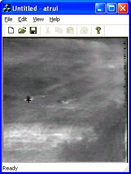
44 Figure 17. ATR GUI Running on PC 34


45 Figure 17. cont. Reconfigure for Cell With a successful model, generation, and execution of the ATR on the PC, we now desire to move it to the Cell for increased performance. With the new SPP kernel in place producing threads for each block and using synchronized communication queues an application that is functional on another supported platform, like ix86 PC, requires minimal modification even though the architectures (and even operating systems) are different. There are just a few necessary changes in order to compile and execute the ATR on the PPE of the Cell. For any application, the user only needs to switch the HostPC hardware platform with the Cell hardware that was defined earlier and rerun the interpreter tool chain (except for the build tool). The fc6-cbe 35
46 system folder will be filled with the corresponding Makefile and definition of main(), and the configuration files will actually require no change. Appendices K and H show the Cell generated system files. Then, the system can be transferred to the Cell and compiled, and the system will execute. However, remember that the PPE is a 64-bit, big-endian core while the PC chip used is 32- bit using the little-endian convention. Therefore, there are a few pivotal changes needed to those process blocks in the ATR that deal with the storage model of the data. It is impossible to give universal specifics for adapting any application because these types of changes are application specific. In the case of the ATR, the byte orders of the input files (the images, MACH filter data, and DCCF filter data) have to be reversed for proper reads. Again, we see the beauty of being able to easily exchange core function algorithms without disturbing the rest of the system. Next, we make more adjustments to the ATR in order to move the computation-heavy tasks to the SPEs. In preparation for this step, deeper analysis of the system was necessary. Though being able to fit code and data onto an SPE s LS is the motivation, much of what is discussed are general observations of the algorithm design of the ATR. Therefore, some of the changes can be applied to the application outside the Cell as well. Memory Consumption It was important to look at the amount of memory required by the system at the high computation moments (the pipelines of the system) because the 36
47 necessary resources for the computational steps must fit onto an SPE s LS along with the corresponding code. Walking through the pipeline blocks from Figure 12, the Multiply component receives an image and the MACH filter data. Each pixel of an image is stored as a complex (real and imaginary parts) value as a single-precision floating-point type (size of four bytes for the Cell). Therefore, with an image of size , it consumes 128 (128 2) 4 = 128 KB of memory half an SPE s LS! What is worse is that the MACH filter data is the same size. These two data structures alone would completely consume an SPE s 256 KB LS, leaving no room for code and other data. The multiplied image continues through the pipeline to TwoDIFFT, Calc_Mean_Std, and Calc_PSR none of these tasks needing much more memory for large data other than the image. The traveling image actually ends its journey in the Calc_PSR process which sends out PSRs for the detected peaks (up to eight peaks). The final block in the pipe, Calculate_Distance, is a rather hefty task. In order to extract and normalize the ROIs and calculate their distances (which involve multiple FFTs and IFFTs among other steps), the task calls for a copy of the original image, a place to store the ROI, another area for storing intermediate results, and the DCCF filter data. Fortunately, this filter data is only 8 KB rather than the 128 KB size of the MACH filter data. Unfortunately, the image, the ROI, and the buffer are 128 KB each. The amount of data sums to more than 384 KB far exceeding that of an SPE s LS and the larger-thanaverage code still must be included. 37
48 Being able to move these computation intensive tasks to the SPEs required an analysis and search for the truly essential resources as well as potential for segmented processing steps. Furthermore, with the initial design, with three pipes, each consisting of five blocks, there are 3 5 = 15 individual tasks and only six SPEs. The methods used for eliminating these dilemmas are discussed in the next section. Algorithm Analysis In order to fit the high-computation pipelines of the ATR application onto the six available SPEs, a deep analysis of the inner workings of the tasks and the detailed flow of the involved data was required. The two major obstacles to be handled were task allocation how the several task blocks should be placed on the SPEs and resource management how the required data could fit onto the limited LSs along with code. For task allocation, the apparent solution to fitting three pipes (of five tasks each) onto six SPEs was providing two SPEs per pipe and actually merging the five tasks in a pipe into two larger tasks. The desired result of these mergers would be two tasks of an equal computational load. Because of the synchronized queues employed in the system, if one task executes longer than the other, the shorter task will end up stalling as it waits for data to be pulled from the interconnecting queue. Quick analysis of both the execution times (on the PPE) and number of floating-point operations (FLOPs or FLOP count) for each block, shown in Table 1, provided an idea for the best division of labor. 38
49 Table 1. Run Time and FLOP Count of Pipe Tasks Task Run Time (µsec) FLOP Count Multiply TwoDIFFT Calc_Mean_Std Calc_PSR Calculate_Distance Based on these values, if the first four tasks were merged into a single task, it would theoretically execute = FLOPs in = 7061 microseconds. The first four tasks combined are still not has hefty as the Calculate_Distance task; however, it is the best configuration for a balanced load. Thus, the pipes were redesigned to contain only two task blocks, as seen in Figure 18, and the corresponding source files for the (originally) first four tasks were glued together into one task, called Mult_TwoDIFFT_Calc_Mean_PSR. Figures show the modeling of this new component. The input ports match those required by the original Multiply component and the output port corresponds to the output port from the Calc_PSR component. The newly defined mult_difft_calc_mean_psr_core, shown in Figure 21 and Figure 22, will actually do little more than invoke the separate cores used by the original separate components multiply_filter_core, ifft_2d_core, calc_mean_std_core, and calc_psrs_core. 39
50 Figure 18. Structure of Merged Pipe in ATR Figure 19. AppDataflow Aspect for Mult_TwoDIFFT_Calc_Mean_PSR 40

51 Figure 20. TypeAspect Aspect for Mult_TwoDIFFT_Calc_Mean_PSR Figure 21. ImplAspect Aspect for Mult_TwoDIFFT_Calc_Mean_PSR Figure 22. Design of mult_difft_calc_mean_psr_core 41
52 To support this, all the source files that correspond to the separate cores are now added to the FileName attribute for Mult_TwoDIFFT_Calc_Mean_PSR and a filename with _spu.c suffix is added to this core and calc_distance_core as well. This satisfies the task allocation requirements specified. With sufficient task allocation, the more difficult job resource management remains, requiring a deep look into what data is required and where in the two tasks. Because of the modularity of the system, the two task blocks can be viewed separately, starting with Mult_TwoDIFFT_Calc_Mean_PSR. Note that though this is one source and one task, the four components it is composed of remain separated within the code. Therefore, the single task or the four separate tasks of which it composed may be referred to interchangeably. Recall that the large data structures existent in the first four tasks are the image and the MACH filter data, both 128 KB each. Furthermore, originally a copy of the progressively processed image was passed through each task because they were threads operating on an image in concurrence with the other tasks, actually consuming = 512 KB. Obviously, this is impossible for the SPE, and fortunately, this is no longer required because these four tasks now operate sequentially. Thus, a single image can be passed through the algorithm and data processing is in-place. However, there is still 256 KB of data. Because the image travels through a majority of the task, it is preferable to keep this structure in the LS. Looking at the MACH filter, it is realized this data structure is only necessary during the Multiply processing, the first part of the task. 42
53 Furthermore, there is a one-to-one relationship between the filter values and the image values. This situation allows us to use part of the MACH filter data on part of the image and then replace it with another part of the filter data for processing the next corresponding section of the image. It should be sufficient to store half the MACH filter (64 KB) at a time, resulting in data storage size of about 192 KB, leaving 64 KB for code (which should also be sufficient). As mentioned earlier, the lengthy Calculate_Distance task originally required over 384 KB of data: the image, a ROI image structure, and an intermediate ROI buffer. This task s algorithm involves acquiring a ROI from a section of the image and through several stages of computation (where the intermediate ROI buffer is required) the distances are calculated. This is repeated eight times, writing a different ROI from the image each time. Because of the repeated use of the image, it is desired to once again retain it in the LS. Furthermore, recall that a ROI has a resolution of only The full image structure, CIMAGE, is used because it matches the necessary structure for the ROI, however, the ROI uses 1/16 th of the structure. The necessary size for an ROI structure is only 32 (32 2) 4 = 8 KB, significantly smaller. By implementing a new, separate data structure for the ROI and the intermediate ROI buffer, shown in Figure 23, the amount of data required for the Calculate_Distance is reduced to about 144 KB, leaving plenty of room on the LS for the other necessary components (i.e. code). 43

54 Figure 23. Defining ROI Data Type The use of the new Allocation attribute for ports is important for this example, but unfortunately only in hindsight. Because of the compactness and thorough resourcefulness of the LS, the simple method of allocating data seemed to be the difference between data corruption and/or incorrect results and successful execution. Understanding that the location of the data in the LS differs with the allocation method as does the use of extra memory for buffering, provides justification for such behavior. Through initial trial and error, we found that a uniform allocation method static or dynamic would not suffice. Only a combination would produce proper results in the end. Later, deeper analysis helped reveal a better understanding of what was occurring. For Mult_DIFFT_Calc_Mean_PSR, the quickest detected fault occurs when attempting to dynamically allocate all the major data structures. When 44
55 attempting to do this, attempting to allocate space for the filter data (after allocating for the image) always results in a NULL return, indicating a lack of space in LS. However, when declaring all structures statically, there is no complaint from the compiler about being unable to allocate LS. This time, a segmentation fault occurs when the library function ifft_1d_r2 is invoked. Observation of the stack pointer shows it in the middle of the LS at address 0xfb90 before the function call followed by a corrupted value of 0xfffff930 after the jump. More details were obtained when attempting to declare the CIMAGE dynamically but keep the other static. Using the GNU debugger and empty function calls for breakpoints, I was able to quickly isolate where the errors were occurring. However, it was discovered movement of these functions would shift the point of error slightly in the address space. This time when moving into ifft_1d_r2, the stack pointer jumps from address 0x2fbb0 to 0x1f950. Unfortunately, the data intensive library function has pointers that traverse the image and eventually overlap with this address and corrupt the stack, causing the application to fail. When the filter structure is dynamically allocated while the image and PSRs structures are static, the image is allocated starting at address 0x1fb90 while the stack pointer sits at 0xf930 in the library function. Keeping the image below the stack seems to be the solution and Mult_DIFFT_Calc_Mean_PSR executes correctly. Similarly, for Calculate_Distance, there were arrangements that caused the program to wrongfully exit when attempting to enter a function or even just a for-loop. Declaring all structures statically cause it to quit when attempting to 45
56 enter a for-loop when adding background to the extracted ROIs. Declaring all structures dynamically managed to allow the program to execute, however the distance values are incorrect and values in the image are corrupted. Incorrect mixed combinations alternate between early exits and producing incorrect distance values. The correct combination found for Calculate_Distance is dynamically allocating the image and PSRs, HDCCF_Filters, and Distances are static structures. This is viewed as a testament to how little space remains on the LS, showing efficient usage of the SPEs. With the proper allocation methods chosen, this potential problem is avoided. With all the updates in place, WrapperGen will generate the new Wrapper code and the corresponding spu files. Appendix L shows the alternate wrapper code for Calculate_Distance while Appendix M contains the corresponding code that is generated for the SPE itself, and Appendix N shows the generated Makefile for the SPE. The PPE acquires passed in data but then sets up the context_data structure, sets up the SPE context, runs the context with the structure passed in, and waits for the context to return. It then finishes by passing forward the processed data. The SPE algorithm involves moving in the context_data structure, moving in the data referenced in the structure, running the core function, and finally moving the processed data back to main memory before returning. Unfortunately, for the ATR, some minimal user intervention is necessary. Because of the necessary changes to the Mult_TwoDIFFT_Calc_Mean_PSR algorithm described above, the generated SPE code needs to be changed to 46

57 reflect this. As shown in Appendix O, the changes (in bold) involve allocating and using only half the MACH filter data at a time. Though, there should only be one core call to mult_difft_calc_mean_psr_core, it first calls the multiply_filter_core function and uses the first half of the MACH filter data. Then, it brings in the second half over top of the first half and calls the proper core, which will call the multiply_filter_core function and expect the second half of the filter data. The necessary changes are minimal and the user does not spend as much as time as he or she could writing this code from scratch. With the task allocation and resource management resolved, we now have the updated ATR model with the Cell as the targeted hardware, shown in Figure 24, and can rerun the interpretive tools to generate the proper system files for the application. Figure 24. Model of ATR Application for Cell 47
58 Replacing Cores for the Cell and Code Optimizations In addition to the new cores resulting from the merged components, we now take advantage of the interchangeability of core functions in order to develop cores that take advantage of the Cell s capabilities. The original algorithms for fft_2d_core and ifft_2d_core are replaced by methods that take advantage of the FFT library provided by IBM s Cell SDK 2.1 [7]. In addition, we replace algorithms for multiply_filter_core, calc_psr_core, and calc_distance_core with techniques that utilize the vector support of the Cell operating on four floatingpoint values at a time. Some data shuffling and a few other minor data manipulation instructions are necessary to meet data arrangement requirements when using these vector instructions, but the exceptional performance increase remains. Finally, with all necessary code having been generated, the user is perfectly capable of making whatever modifications he or she desires (similar to the necessary changes to Mult_TwoDIFFT_Calc_Mean_PSR mentioned earlier), typically in order to further increase performance. For the ATR, we observed a redundancy in repetitive acquisition of static filter data. By storing these structures locally with the processes (Multiply and Calculate_Distance), it reduces delays due to waiting for the data and unnecessary copying. Execution on Cell After a successful compilation on the Cell, we execute the ATR with a GUI overlay similar to the PC version, shown in Figure
59 Figure 25. ATR GUI running on Cell 49


60 Figure 25. cont. 50
The Pennsylvania State University. The Graduate School. College of Engineering PFFTC: AN IMPROVED FAST FOURIER TRANSFORM
 The Pennsylvania State University The Graduate School College of Engineering PFFTC: AN IMPROVED FAST FOURIER TRANSFORM FOR THE IBM CELL BROADBAND ENGINE A Thesis in Computer Science and Engineering by
IBM Cell Processor. Gilbert Hendry Mark Kretschmann
 IBM Cell Processor Gilbert Hendry Mark Kretschmann Architectural components Architectural security Programming Models Compiler Applications Performance Power and Cost Conclusion Outline Cell Architecture:
Introduction to Computing and Systems Architecture
 Introduction to Computing and Systems Architecture 1. Computability A task is computable if a sequence of instructions can be described which, when followed, will complete such a task. This says little
high performance medical reconstruction using stream programming paradigms
 high performance medical reconstruction using stream programming paradigms This Paper describes the implementation and results of CT reconstruction using Filtered Back Projection on various stream programming
Parallel Computing: Parallel Architectures Jin, Hai
 Parallel Computing: Parallel Architectures Jin, Hai School of Computer Science and Technology Huazhong University of Science and Technology Peripherals Computer Central Processing Unit Main Memory Computer
Computer Systems Architecture I. CSE 560M Lecture 19 Prof. Patrick Crowley
 Computer Systems Architecture I CSE 560M Lecture 19 Prof. Patrick Crowley Plan for Today Announcement No lecture next Wednesday (Thanksgiving holiday) Take Home Final Exam Available Dec 7 Due via email
CellSs Making it easier to program the Cell Broadband Engine processor
 Perez, Bellens, Badia, and Labarta CellSs Making it easier to program the Cell Broadband Engine processor Presented by: Mujahed Eleyat Outline Motivation Architecture of the cell processor Challenges of
Sony/Toshiba/IBM (STI) CELL Processor. Scientific Computing for Engineers: Spring 2008
 CELL Processor. Scientific Computing for Engineers: Spring 2008") Sony/Toshiba/IBM (STI) CELL Processor Scientific Computing for Engineers: Spring 2008 Nec Hercules Contra Plures Chip's performance is related to its cross section same area 2 performance (Pollack's Rule)
Sony/Toshiba/IBM (STI) CELL Processor Scientific Computing for Engineers: Spring 2008 Nec Hercules Contra Plures Chip's performance is related to its cross section same area 2 performance (Pollack's Rule)
Cell Broadband Engine. Spencer Dennis Nicholas Barlow
 Cell Broadband Engine Spencer Dennis Nicholas Barlow The Cell Processor Objective: [to bring] supercomputer power to everyday life Bridge the gap between conventional CPU s and high performance GPU s History
Mapping Multiple Processes onto SPEs of the CELL BE Platform using the SCO Model of Computation
 Mapping Multiple Processes onto SPEs of the CELL BE Platform using the SCO Model of Computation A Master s thesis Computer Science Nadia Ramjiawan January 19, 2009 Abstract The Cell Broadband Engine platform
Introduction to CELL B.E. and GPU Programming. Agenda
 Introduction to CELL B.E. and GPU Programming Department of Electrical & Computer Engineering Rutgers University Agenda Background CELL B.E. Architecture Overview CELL B.E. Programming Environment GPU
David R. Mackay, Ph.D. Libraries play an important role in threading software to run faster on Intel multi-core platforms.
 Whitepaper Introduction A Library Based Approach to Threading for Performance David R. Mackay, Ph.D. Libraries play an important role in threading software to run faster on Intel multi-core platforms.
CISC 879 Software Support for Multicore Architectures Spring Student Presentation 6: April 8. Presenter: Pujan Kafle, Deephan Mohan
 CISC 879 Software Support for Multicore Architectures Spring 2008 Student Presentation 6: April 8 Presenter: Pujan Kafle, Deephan Mohan Scribe: Kanik Sem The following two papers were presented: A Synchronous
COSC 6385 Computer Architecture - Data Level Parallelism (III) The Intel Larrabee, Intel Xeon Phi and IBM Cell processors
 The Intel Larrabee, Intel Xeon Phi and IBM Cell processors") COSC 6385 Computer Architecture - Data Level Parallelism (III) The Intel Larrabee, Intel Xeon Phi and IBM Cell processors Edgar Gabriel Fall 2018 References Intel Larrabee: [1] L. Seiler, D. Carmean, E.
COSC 6385 Computer Architecture - Data Level Parallelism (III) The Intel Larrabee, Intel Xeon Phi and IBM Cell processors Edgar Gabriel Fall 2018 References Intel Larrabee: [1] L. Seiler, D. Carmean, E.
Software Development Kit for Multicore Acceleration Version 3.0
 Software Development Kit for Multicore Acceleration Version 3.0 Programming Tutorial SC33-8410-00 Software Development Kit for Multicore Acceleration Version 3.0 Programming Tutorial SC33-8410-00 Note
Parallel Exact Inference on the Cell Broadband Engine Processor
 Parallel Exact Inference on the Cell Broadband Engine Processor Yinglong Xia and Viktor K. Prasanna {yinglonx, prasanna}@usc.edu University of Southern California http://ceng.usc.edu/~prasanna/ SC 08 Overview
Spring 2011 Prof. Hyesoon Kim
 Spring 2011 Prof. Hyesoon Kim PowerPC-base Core @3.2GHz 1 VMX vector unit per core 512KB L2 cache 7 x SPE @3.2GHz 7 x 128b 128 SIMD GPRs 7 x 256KB SRAM for SPE 1 of 8 SPEs reserved for redundancy total
Cell Processor and Playstation 3
 Cell Processor and Playstation 3 Guillem Borrell i Nogueras February 24, 2009 Cell systems Bad news More bad news Good news Q&A IBM Blades QS21 Cell BE based. 8 SPE 460 Gflops Float 20 GFLops Double QS22
PowerVR Hardware. Architecture Overview for Developers
 Public Imagination Technologies PowerVR Hardware Public. This publication contains proprietary information which is subject to change without notice and is supplied 'as is' without warranty of any kind.
Computer Architecture
 Computer Architecture Slide Sets WS 2013/2014 Prof. Dr. Uwe Brinkschulte M.Sc. Benjamin Betting Part 10 Thread and Task Level Parallelism Computer Architecture Part 10 page 1 of 36 Prof. Dr. Uwe Brinkschulte,
Accelerated Library Framework for Hybrid-x86
 Software Development Kit for Multicore Acceleration Version 3.0 Accelerated Library Framework for Hybrid-x86 Programmer s Guide and API Reference Version 1.0 DRAFT SC33-8406-00 Software Development Kit
Scheduling the Intel Core i7
 Third Year Project Report University of Manchester SCHOOL OF COMPUTER SCIENCE Scheduling the Intel Core i7 Ibrahim Alsuheabani Degree Programme: BSc Software Engineering Supervisor: Prof. Alasdair Rawsthorne
FFTC: Fastest Fourier Transform on the IBM Cell Broadband Engine. David A. Bader, Virat Agarwal
 FFTC: Fastest Fourier Transform on the IBM Cell Broadband Engine David A. Bader, Virat Agarwal Cell System Features Heterogeneous multi-core system architecture Power Processor Element for control tasks
The University of Texas at Austin
 EE382N: Principles in Computer Architecture Parallelism and Locality Fall 2009 Lecture 24 Stream Processors Wrapup + Sony (/Toshiba/IBM) Cell Broadband Engine Mattan Erez The University of Texas at Austin
AN 831: Intel FPGA SDK for OpenCL
 AN 831: Intel FPGA SDK for OpenCL Host Pipelined Multithread Subscribe Send Feedback Latest document on the web: PDF HTML Contents Contents 1 Intel FPGA SDK for OpenCL Host Pipelined Multithread...3 1.1
Cache Justification for Digital Signal Processors
 Cache Justification for Digital Signal Processors by Michael J. Lee December 3, 1999 Cache Justification for Digital Signal Processors By Michael J. Lee Abstract Caches are commonly used on general-purpose
Performance of Multicore LUP Decomposition
 Performance of Multicore LUP Decomposition Nathan Beckmann Silas Boyd-Wickizer May 3, 00 ABSTRACT This paper evaluates the performance of four parallel LUP decomposition implementations. The implementations
CSCI-GA Multicore Processors: Architecture & Programming Lecture 10: Heterogeneous Multicore
 CSCI-GA.3033-012 Multicore Processors: Architecture & Programming Lecture 10: Heterogeneous Multicore Mohamed Zahran (aka Z) mzahran@cs.nyu.edu http://www.mzahran.com Status Quo Previously, CPU vendors
1. Microprocessor Architectures. 1.1 Intel 1.2 Motorola
 1. Microprocessor Architectures 1.1 Intel 1.2 Motorola 1.1 Intel The Early Intel Microprocessors The first microprocessor to appear in the market was the Intel 4004, a 4-bit data bus device. This device
Crypto On the Playstation 3
 Crypto On the Playstation 3 Neil Costigan School of Computing, DCU. neil.costigan@computing.dcu.ie +353.1.700.6916 PhD student / 2 nd year of research. Supervisor : - Dr Michael Scott. IRCSET funded. Playstation
With Fixed Point or Floating Point Processors!!
 Product Information Sheet High Throughput Digital Signal Processor OVERVIEW With Fixed Point or Floating Point Processors!! Performance Up to 14.4 GIPS or 7.7 GFLOPS Peak Processing Power Continuous Input
A Streaming Computation Framework for the Cell Processor. Xin David Zhang
 A Streaming Computation Framework for the Cell Processor by Xin David Zhang Submitted to the Department of Electrical Engineering and Computer Science in Partial Fulfillment of the Requirements for the
CS 326: Operating Systems. Process Execution. Lecture 5
 CS 326: Operating Systems Process Execution Lecture 5 Today s Schedule Process Creation Threads Limited Direct Execution Basic Scheduling 2/5/18 CS 326: Operating Systems 2 Today s Schedule Process Creation
Main Points of the Computer Organization and System Software Module
 Main Points of the Computer Organization and System Software Module You can find below the topics we have covered during the COSS module. Reading the relevant parts of the textbooks is essential for a
This Unit: Putting It All Together. CIS 371 Computer Organization and Design. What is Computer Architecture? Sources
 This Unit: Putting It All Together CIS 371 Computer Organization and Design Unit 15: Putting It All Together: Anatomy of the XBox 360 Game Console Application OS Compiler Firmware CPU I/O Memory Digital
The Pennsylvania State University. The Graduate School. College of Engineering A NEURAL NETWORK BASED CLASSIFIER ON THE CELL BROADBAND ENGINE
 The Pennsylvania State University The Graduate School College of Engineering A NEURAL NETWORK BASED CLASSIFIER ON THE CELL BROADBAND ENGINE A Thesis in Electrical Engineering by Srijith Rajamohan 2009
INSTITUTO SUPERIOR TÉCNICO. Architectures for Embedded Computing
 UNIVERSIDADE TÉCNICA DE LISBOA INSTITUTO SUPERIOR TÉCNICO Departamento de Engenharia Informática Architectures for Embedded Computing MEIC-A, MEIC-T, MERC Lecture Slides Version 3.0 - English Lecture 12
High Performance Computing on GPUs using NVIDIA CUDA
 High Performance Computing on GPUs using NVIDIA CUDA Slides include some material from GPGPU tutorial at SIGGRAPH2007: http://www.gpgpu.org/s2007 1 Outline Motivation Stream programming Simplified HW and
Lecture 5: Process Description and Control Multithreading Basics in Interprocess communication Introduction to multiprocessors
 Lecture 5: Process Description and Control Multithreading Basics in Interprocess communication Introduction to multiprocessors 1 Process:the concept Process = a program in execution Example processes:
( ZIH ) Center for Information Services and High Performance Computing. Event Tracing and Visualization for Cell Broadband Engine Systems
 Center for Information Services and High Performance Computing. Event Tracing and Visualization for Cell Broadband Engine Systems") ( ZIH ) Center for Information Services and High Performance Computing Event Tracing and Visualization for Cell Broadband Engine Systems ( daniel.hackenberg@zih.tu-dresden.de ) Daniel Hackenberg Cell Broadband
( ZIH ) Center for Information Services and High Performance Computing Event Tracing and Visualization for Cell Broadband Engine Systems ( daniel.hackenberg@zih.tu-dresden.de ) Daniel Hackenberg Cell Broadband
Memory. From Chapter 3 of High Performance Computing. c R. Leduc
 Memory From Chapter 3 of High Performance Computing c 2002-2004 R. Leduc Memory Even if CPU is infinitely fast, still need to read/write data to memory. Speed of memory increasing much slower than processor
Roadrunner. By Diana Lleva Julissa Campos Justina Tandar
 Roadrunner By Diana Lleva Julissa Campos Justina Tandar Overview Roadrunner background On-Chip Interconnect Number of Cores Memory Hierarchy Pipeline Organization Multithreading Organization Roadrunner
Cell Programming Tips & Techniques
 Cell Programming Tips & Techniques Course Code: L3T2H1-58 Cell Ecosystem Solutions Enablement 1 Class Objectives Things you will learn Key programming techniques to exploit cell hardware organization and
CHAPTER 3 - PROCESS CONCEPT
 CHAPTER 3 - PROCESS CONCEPT 1 OBJECTIVES Introduce a process a program in execution basis of all computation Describe features of processes: scheduling, creation, termination, communication Explore interprocess
Cellular Planets: Optimizing Planetary Simulations for the Cell Processor
 Trinity University Digital Commons @ Trinity Computer Science Honors Theses Computer Science Department 4-18-2007 Cellular Planets: Optimizing Planetary Simulations for the Cell Processor Brent Peckham
CS6303 Computer Architecture Regulation 2013 BE-Computer Science and Engineering III semester 2 MARKS
 CS6303 Computer Architecture Regulation 2013 BE-Computer Science and Engineering III semester 2 MARKS UNIT-I OVERVIEW & INSTRUCTIONS 1. What are the eight great ideas in computer architecture? The eight
CONSOLE ARCHITECTURE
 CONSOLE ARCHITECTURE Introduction Part 1 What is a console? Console components Differences between consoles and PCs Benefits of console development The development environment Console game design What
Laboratory Exercise 3 Comparative Analysis of Hardware and Emulation Forms of Signed 32-Bit Multiplication
 Laboratory Exercise 3 Comparative Analysis of Hardware and Emulation Forms of Signed 32-Bit Multiplication Introduction All processors offer some form of instructions to add, subtract, and manipulate data.
Optimising for the p690 memory system
 Optimising for the p690 memory Introduction As with all performance optimisation it is important to understand what is limiting the performance of a code. The Power4 is a very powerful micro-processor
Neil Costigan School of Computing, Dublin City University PhD student / 2 nd year of research.
 Crypto On the Cell Neil Costigan School of Computing, Dublin City University. neil.costigan@computing.dcu.ie +353.1.700.6916 PhD student / 2 nd year of research. Supervisor : - Dr Michael Scott. IRCSET
This Unit: Putting It All Together. CIS 501 Computer Architecture. What is Computer Architecture? Sources
 This Unit: Putting It All Together CIS 501 Computer Architecture Unit 12: Putting It All Together: Anatomy of the XBox 360 Game Console Application OS Compiler Firmware CPU I/O Memory Digital Circuits
Cell SDK and Best Practices
 Cell SDK and Best Practices Stefan Lutz Florian Braune Hardware-Software-Co-Design Universität Erlangen-Nürnberg siflbrau@mb.stud.uni-erlangen.de Stefan.b.lutz@mb.stud.uni-erlangen.de 1 Overview - Introduction
CS370 Operating Systems
 CS370 Operating Systems Colorado State University Yashwant K Malaiya Spring 2018 Lecture 2 Slides based on Text by Silberschatz, Galvin, Gagne Various sources 1 1 2 What is an Operating System? What is
CS370 Operating Systems
 CS370 Operating Systems Colorado State University Yashwant K Malaiya Fall 2016 Lecture 2 Slides based on Text by Silberschatz, Galvin, Gagne Various sources 1 1 2 System I/O System I/O (Chap 13) Central
Network Interface Architecture and Prototyping for Chip and Cluster Multiprocessors
 University of Crete School of Sciences & Engineering Computer Science Department Master Thesis by Michael Papamichael Network Interface Architecture and Prototyping for Chip and Cluster Multiprocessors
Distributed Operation Layer Integrated SW Design Flow for Mapping Streaming Applications to MPSoC
 Distributed Operation Layer Integrated SW Design Flow for Mapping Streaming Applications to MPSoC Iuliana Bacivarov, Wolfgang Haid, Kai Huang, and Lothar Thiele ETH Zürich MPSoCs are Hard to program (
High Performance Computing. University questions with solution
 High Performance Computing University questions with solution Q1) Explain the basic working principle of VLIW processor. (6 marks) The following points are basic working principle of VLIW processor. The
Concurrent Programming with the Cell Processor. Dietmar Kühl Bloomberg L.P.
 Concurrent Programming with the Cell Processor Dietmar Kühl Bloomberg L.P. dietmar.kuehl@gmail.com Copyright Notice 2009 Bloomberg L.P. Permission is granted to copy, distribute, and display this material,
Four Components of a Computer System
 Four Components of a Computer System Operating System Concepts Essentials 2nd Edition 1.1 Silberschatz, Galvin and Gagne 2013 Operating System Definition OS is a resource allocator Manages all resources
FYS Data acquisition & control. Introduction. Spring 2018 Lecture #1. Reading: RWI (Real World Instrumentation) Chapter 1.
 Chapter 1.") FYS3240-4240 Data acquisition & control Introduction Spring 2018 Lecture #1 Reading: RWI (Real World Instrumentation) Chapter 1. Bekkeng 14.01.2018 Topics Instrumentation: Data acquisition and control
FYS3240-4240 Data acquisition & control Introduction Spring 2018 Lecture #1 Reading: RWI (Real World Instrumentation) Chapter 1. Bekkeng 14.01.2018 Topics Instrumentation: Data acquisition and control
Copyright 2013 Thomas W. Doeppner. IX 1
 Copyright 2013 Thomas W. Doeppner. IX 1 If we have only one thread, then, no matter how many processors we have, we can do only one thing at a time. Thus multiple threads allow us to multiplex the handling
This Unit: Putting It All Together. CIS 371 Computer Organization and Design. Sources. What is Computer Architecture?
 This Unit: Putting It All Together CIS 371 Computer Organization and Design Unit 15: Putting It All Together: Anatomy of the XBox 360 Game Console Application OS Compiler Firmware CPU I/O Memory Digital
Tutorial: Analyzing MPI Applications. Intel Trace Analyzer and Collector Intel VTune Amplifier XE
 Tutorial: Analyzing MPI Applications Intel Trace Analyzer and Collector Intel VTune Amplifier XE Contents Legal Information... 3 1. Overview... 4 1.1. Prerequisites... 5 1.1.1. Required Software... 5 1.1.2.
15-740/ Computer Architecture, Fall 2011 Midterm Exam II
 15-740/18-740 Computer Architecture, Fall 2011 Midterm Exam II Instructor: Onur Mutlu Teaching Assistants: Justin Meza, Yoongu Kim Date: December 2, 2011 Name: Instructions: Problem I (69 points) : Problem
Chapter 13: I/O Systems
 Chapter 13: I/O Systems DM510-14 Chapter 13: I/O Systems I/O Hardware Application I/O Interface Kernel I/O Subsystem Transforming I/O Requests to Hardware Operations STREAMS Performance 13.2 Objectives
Unit 11: Putting it All Together: Anatomy of the XBox 360 Game Console
 Computer Architecture Unit 11: Putting it All Together: Anatomy of the XBox 360 Game Console Slides originally developed by Milo Martin & Amir Roth at University of Pennsylvania! Computer Architecture
Evaluating the Portability of UPC to the Cell Broadband Engine
 Evaluating the Portability of UPC to the Cell Broadband Engine Dipl. Inform. Ruben Niederhagen JSC Cell Meeting CHAIR FOR OPERATING SYSTEMS Outline Introduction UPC Cell UPC on Cell Mapping Compiler and
CS 426 Parallel Computing. Parallel Computing Platforms
 CS 426 Parallel Computing Parallel Computing Platforms Ozcan Ozturk http://www.cs.bilkent.edu.tr/~ozturk/cs426/ Slides are adapted from ``Introduction to Parallel Computing'' Topic Overview Implicit Parallelism:
ACCELERATED COMPLEX EVENT PROCESSING WITH GRAPHICS PROCESSING UNITS
 ACCELERATED COMPLEX EVENT PROCESSING WITH GRAPHICS PROCESSING UNITS Prabodha Srimal Rodrigo Registration No. : 138230V Degree of Master of Science Department of Computer Science & Engineering University
PowerPC on NetFPGA CSE 237B. Erik Rubow
 PowerPC on NetFPGA CSE 237B Erik Rubow NetFPGA PCI card + FPGA + 4 GbE ports FPGA (Virtex II Pro) has 2 PowerPC hard cores Untapped resource within NetFPGA community Goals Evaluate performance of on chip
ARM Processors for Embedded Applications
 ARM Processors for Embedded Applications Roadmap for ARM Processors ARM Architecture Basics ARM Families AMBA Architecture 1 Current ARM Core Families ARM7: Hard cores and Soft cores Cache with MPU or
Optimizing Data Sharing and Address Translation for the Cell BE Heterogeneous CMP
 Optimizing Data Sharing and Address Translation for the Cell BE Heterogeneous CMP Michael Gschwind IBM T.J. Watson Research Center Cell Design Goals Provide the platform for the future of computing 10
ASSEMBLY LANGUAGE MACHINE ORGANIZATION
 ASSEMBLY LANGUAGE MACHINE ORGANIZATION CHAPTER 3 1 Sub-topics The topic will cover: Microprocessor architecture CPU processing methods Pipelining Superscalar RISC Multiprocessing Instruction Cycle Instruction
Chapter 3: Process Concept
 Chapter 3: Process Concept Chapter 3: Process Concept Process Concept Process Scheduling Operations on Processes Inter-Process Communication (IPC) Communication in Client-Server Systems Objectives 3.2
Chapter 3: Process Concept
 Chapter 3: Process Concept Chapter 3: Process Concept Process Concept Process Scheduling Operations on Processes Inter-Process Communication (IPC) Communication in Client-Server Systems Objectives 3.2
CS140 Final Project. Nathan Crandall, Dane Pitkin, Introduction:
 Nathan Crandall, 3970001 Dane Pitkin, 4085726 CS140 Final Project Introduction: Our goal was to parallelize the Breadth-first search algorithm using Cilk++. This algorithm works by starting at an initial
Misc. Third Generation Batch Multiprogramming. Fourth Generation Time Sharing. Last Time Evolution of OSs
 Third Generation Batch Multiprogramming Misc. Problem: but I/O still expensive; can happen in middle of job Idea: have a pool of ready jobs in memory, switch to one when another needs I/O When one job
Amir Khorsandi Spring 2012
 Introduction to Amir Khorsandi Spring 2012 History Motivation Architecture Software Environment Power of Parallel lprocessing Conclusion 5/7/2012 9:48 PM ٢ out of 37 5/7/2012 9:48 PM ٣ out of 37 IBM, SCEI/Sony,
Double-Precision Matrix Multiply on CUDA
 Double-Precision Matrix Multiply on CUDA Parallel Computation (CSE 60), Assignment Andrew Conegliano (A5055) Matthias Springer (A995007) GID G--665 February, 0 Assumptions All matrices are square matrices
Lecture 25: Board Notes: Threads and GPUs
 Lecture 25: Board Notes: Threads and GPUs Announcements: - Reminder: HW 7 due today - Reminder: Submit project idea via (plain text) email by 11/24 Recap: - Slide 4: Lecture 23: Introduction to Parallel
All About the Cell Processor
 All About the Cell H. Peter Hofstee, Ph. D. IBM Systems and Technology Group SCEI/Sony Toshiba IBM Design Center Austin, Texas Acknowledgements Cell is the result of a deep partnership between SCEI/Sony,
CSCI 402: Computer Architectures. Parallel Processors (2) Fengguang Song Department of Computer & Information Science IUPUI.
 Fengguang Song Department of Computer & Information Science IUPUI.") CSCI 402: Computer Architectures Parallel Processors (2) Fengguang Song Department of Computer & Information Science IUPUI 6.6 - End Today s Contents GPU Cluster and its network topology The Roofline performance
CSCI 402: Computer Architectures Parallel Processors (2) Fengguang Song Department of Computer & Information Science IUPUI 6.6 - End Today s Contents GPU Cluster and its network topology The Roofline performance
SDACCEL DEVELOPMENT ENVIRONMENT. The Xilinx SDAccel Development Environment. Bringing The Best Performance/Watt to the Data Center
 SDAccel Environment The Xilinx SDAccel Development Environment Bringing The Best Performance/Watt to the Data Center Introduction Data center operators constantly seek more server performance. Currently
Parallel Computer Architecture and Programming Written Assignment 3
 Parallel Computer Architecture and Programming Written Assignment 3 50 points total. Due Monday, July 17 at the start of class. Problem 1: Message Passing (6 pts) A. (3 pts) You and your friend liked the
Data Communication and Synchronization
 Software Development Kit for Multicore Acceleration Version 3.0 Data Communication and Synchronization for Cell Programmer s Guide and API Reference Version 1.0 DRAFT SC33-8407-00 Software Development
Chapter 12: I/O Systems
 Chapter 12: I/O Systems Chapter 12: I/O Systems I/O Hardware! Application I/O Interface! Kernel I/O Subsystem! Transforming I/O Requests to Hardware Operations! STREAMS! Performance! Silberschatz, Galvin
Chapter 13: I/O Systems
 Chapter 13: I/O Systems Chapter 13: I/O Systems I/O Hardware Application I/O Interface Kernel I/O Subsystem Transforming I/O Requests to Hardware Operations STREAMS Performance Silberschatz, Galvin and
Chapter 12: I/O Systems. Operating System Concepts Essentials 8 th Edition
 Chapter 12: I/O Systems Silberschatz, Galvin and Gagne 2011 Chapter 12: I/O Systems I/O Hardware Application I/O Interface Kernel I/O Subsystem Transforming I/O Requests to Hardware Operations STREAMS
Memory Architectures. Week 2, Lecture 1. Copyright 2009 by W. Feng. Based on material from Matthew Sottile.
 Week 2, Lecture 1 Copyright 2009 by W. Feng. Based on material from Matthew Sottile. Directory-Based Coherence Idea Maintain pointers instead of simple states with each cache block. Ingredients Data owners
A Simulation: Improving Throughput and Reducing PCI Bus Traffic by. Caching Server Requests using a Network Processor with Memory
 Shawn Koch Mark Doughty ELEC 525 4/23/02 A Simulation: Improving Throughput and Reducing PCI Bus Traffic by Caching Server Requests using a Network Processor with Memory 1 Motivation and Concept The goal
Chapter 13: I/O Systems
 COP 4610: Introduction to Operating Systems (Spring 2015) Chapter 13: I/O Systems Zhi Wang Florida State University Content I/O hardware Application I/O interface Kernel I/O subsystem I/O performance Objectives
Optimizing for DirectX Graphics. Richard Huddy European Developer Relations Manager
 Optimizing for DirectX Graphics Richard Huddy European Developer Relations Manager Also on today from ATI... Start & End Time: 12:00pm 1:00pm Title: Precomputed Radiance Transfer and Spherical Harmonic
PowerPC 740 and 750
 368 floating-point registers. A reorder buffer with 16 elements is used as well to support speculative execution. The register file has 12 ports. Although instructions can be executed out-of-order, in-order
Chapter 5A. Large and Fast: Exploiting Memory Hierarchy
 Chapter 5A Large and Fast: Exploiting Memory Hierarchy Memory Technology Static RAM (SRAM) Fast, expensive Dynamic RAM (DRAM) In between Magnetic disk Slow, inexpensive Ideal memory Access time of SRAM
FPGA Solutions: Modular Architecture for Peak Performance
 FPGA Solutions: Modular Architecture for Peak Performance Real Time & Embedded Computing Conference Houston, TX June 17, 2004 Andy Reddig President & CTO andyr@tekmicro.com Agenda Company Overview FPGA
Introduction to GPU hardware and to CUDA
 Introduction to GPU hardware and to CUDA Philip Blakely Laboratory for Scientific Computing, University of Cambridge Philip Blakely (LSC) GPU introduction 1 / 35 Course outline Introduction to GPU hardware
TUNING CUDA APPLICATIONS FOR MAXWELL
 TUNING CUDA APPLICATIONS FOR MAXWELL DA-07173-001_v7.0 March 2015 Application Note TABLE OF CONTENTS Chapter 1. Maxwell Tuning Guide... 1 1.1. NVIDIA Maxwell Compute Architecture... 1 1.2. CUDA Best Practices...2
RUN-TIME RECONFIGURABLE IMPLEMENTATION OF DSP ALGORITHMS USING DISTRIBUTED ARITHMETIC. Zoltan Baruch
 RUN-TIME RECONFIGURABLE IMPLEMENTATION OF DSP ALGORITHMS USING DISTRIBUTED ARITHMETIC Zoltan Baruch Computer Science Department, Technical University of Cluj-Napoca, 26-28, Bariţiu St., 3400 Cluj-Napoca,
COMPUTER SCIENCE 4500 OPERATING SYSTEMS
 Last update: 3/28/2017 COMPUTER SCIENCE 4500 OPERATING SYSTEMS 2017 Stanley Wileman Module 9: Memory Management Part 1 In This Module 2! Memory management functions! Types of memory and typical uses! Simple
Parallelism Marco Serafini
 Parallelism Marco Serafini COMPSCI 590S Lecture 3 Announcements Reviews First paper posted on website Review due by this Wednesday 11 PM (hard deadline) Data Science Career Mixer (save the date!) November