TESTING HIGH SPEED FIBER LINKS
|
|
|
- Jennifer Stevenson
- 5 years ago
- Views:
Transcription

1 TESTING HIGH SPEED FIBER LINKS Rodney Casteel, RCDD, DCDC, NTS, OSP - CommScope, Chair TIA FOTC Tyler Vander Ploeg, RCDD - Viavi Solutions Jamie Humphreys - EXFO Rob Gilberti - AFL Jim Davis - Fluke Networks
2 Agenda Intro to FOTC Basic/Tier 1 Fiber Certification Tier-2 OTDR testing & troubleshooting Short break A Live demo
3 Fiber Optics Technology Consortium Overview: Part of the Telecommunications Industry Association ( 2013, we had been known as the Fiber Optics LAN Section (FOLS). Our new name was chosen to reflect our expanding charter. Formed 23 years ago Mission: to educate users about the benefits of deploying fiber in customer-owned networks FOTC provides vendor-neutral information
4 Fiber Optics Technology Consortium Current Members AFL CommScope Corning EXFO Fluke Networks General Cable OFS Current Members Legrand Panduit Sumitomo Electric Lightwave Superior Essex The Siemon Company Viavi
5 Fiber Optics Technology Consortium Maintain a website with Fiber FAQs, White Papers and other resources Developed and maintain a free Cost Model that allows users to compare installed first costs of several architectures. Host a webinar series throughout the year with all webinars available on demand. Speak at industry conferences like BICSI Contribute to industry publications Like BICSI News. Conduct market research like the surveys today
6 Fiber Optics Technology Consortium Recent Webinars Available on Demand Keeping up with High Speed Migration in the Data Center Data Center Design, Planning & Upcoming Changes to TIA-942 Best Practices for Achieving Tier 1 Fiber Certification Visit or our channel on BrightTalk Webinars are eligible for CEC credit for up to two years after they are first broadcast. liz@goldsmithpr.com if you have completed a webinar and want to receive your CEC.
7 Important Notice Any product(s) identified or identifiable via a trade name or otherwise in this presentation as a product(s) supplied by a particular supplier(s) is provided for the convenience of users of this presentation and does not constitute an endorsement of any kind by TIA of the product(s) named. This information may be provided as an example of suitable product(s) available commercially. Equivalent product(s) may be used if they can be shown to lead to the same results.
8 Basic/Tier 1 Fiber Certification Tyler Vander Ploeg, RCDD Fiber Solutions Marketing Manager VIAVI Solutions Orlando, FL, February 5, 2018
9 Agenda Testing Basics Standards / Channels and Links / db vs. dbm Tier 1 Testing Certification Requirements Main Challenges Reference methods Tier 1 Testing for MPO Additional Challenges Conclusion/Q&A
10 Testing Basics
11 Relevant TIA Standards D Optical fiber cabling and component standard Updated to revision D in June 2016 Transmission performance and test requirements in Clause 7 Annex E (informative) provided guidelines for field testing ANSI/TIA C-2015 Test procedures for installed multimode fiber cable plant Released in April 2015 Adaptation of IEC Ed. 2.0 Encircled Flux for 850nm/50 micron ANSI/TIA A Test procedure for installed single mode fiber cable plant Released in July 2015 Adoption of IEC Ed 2.0 What about MPO? Existing fiber test standards do not address MPO-specific concerns SC 86C WG 1 released a Technical Report (TR) on testing MPO Testing Multi-fiber optic cable plant terminated with MPO connectors
12 Tests Defined in Standards Both TIA and ISO/IEC standards specify to tiers of certification Tier 1 (or basic): loss, length, and polarity Tier 2 (or extended): Optical time domain reflectometer (OTDR) Tier 2 (extended) tests are an optional addition to tier 1 (basic) tests Fiber end-face inspection and certification is also a requirement to ensure pristine end-face condition PRIOR to mating


13 Channels and Links Equipment Cord Connections and splices possible Equipment Cord Equipment Optical Patch Panel Link Optical Patch Panel Equipment Channel
14 db vs. dbm dbm = an ABSOLUTE measurement of power (1mW = 0dBm) db = a RELATIVE measurement Loss is a Reference Measurement (not an Absolute Measurement) First step in an accurate loss measurement is performing a reference! Purpose of a reference is to zero out any test cables and connectors 1 mw = 0 dbm Tx 2 db 5 db.5 db Loss = 7.5 db -7.5 dbm Rx
15 Testing to a specific Application Application is the protocol that will ride on the fiber (Typically Ethernet or Fiber Channel) Most Enterprise Optical Loss Test Sets will report Compliant Networks based on loss measurement Cautions! Can PASS standards-based generic limit, but have too much loss for specific application Most testing performed is on links but applications run on channels If the Application to be carried on the fiber is known use Application (Network) limit on your test device
16 Tier 1 Testing
 Document")
17 Tier 1 Certification Requirements Measure Length Measure Loss Check Polarity Ensure Loss does not exceed a limit (AKA loss budget) Document results
18 Main Challenges with Tier 1 Testing 1. Contaminated Fiber Endfaces 2. Multimode Transmitter Launch Condition 3. Not using Test Reference Cords (TRCs) 4. Errors with Referencing
19 What Makes a BAD Fiber Connection? Today s connector design and production techniques have eliminated most of the challenges to achieving Core Alignment and Physical Contact. What remains challenging is maintaining a Pristine End-face. As a result, CONTAMINATION is the #1 source of troubleshooting in optical networks. A single particle mated into the core of a fiber can cause significant back reflection, insertion loss and even equipment damage. Light Core Back Reflection Insertion Loss Cladding DIRT

20 Follow this simple INSPECT BEFORE YOU CONNECT process to ensure fiber end faces are clean prior to mating connectors.
21 Multimode Launch Conditions Different multimode light sources = different modal power distributions Commonly referred to as launch conditions Launch conditions directly impact link loss measurements accuracy LED overfills a multimode fiber tending to overstate loss Laser underfills a multimode fiber tending to understate loss Lower modes Cladding Higher modes Lower modes Cladding Overfilled source (LED) Core Cladding Underfilled source (Laser) Core Cladding

22 IEC sets standards for MM launch conditions Ratio between the transmitted power at a given radius of the fiber core and the total injected power 1 0,9 0,8 0,7 Defined in IEC standard to characterize the launch conditions of MM test sources Encircled flux 0,6 0,5 0,4 0,3 0,2 0,1 Is measured at the launch cord connector NOT at the source output radius (µm) Replaces older launch condition requires such as Coupled Power Ratio (CPR) Can be achieved by using a universal or matched modal controller

23 MM Launch Condition Source: IEC
24 Universal and Matched Controllers Universal Controller For legacy sources Adds a black box to the output of the legacy source Matched Controller Specific source matched with specific launch cord Launch cord may have additional conditioning Specific Source Black Box (optional) Legacy Source Black Box Universal Controller Matched Controller Launch Cord
25 Test Reference Cords (TRCs) Use high performance (reference grade) connectors Optimal optical and geometrical characteristics Numerical aperture (NA) Core/ferrule concentricity When mated with other TRCs produce near zero loss Minimizes uncertainty Called for in various standards for loss measurements of installed fiber cabling Source: IEC

26 Losses associated with mating of TRCs Source: IEC Source: IEC
27 Correct Steps for Referencing Turn units on and let sources warm up for 5 min Select and configure appropriate limit Set reference method on device Connect devices together according to reference method selected (+ Inspect) Perform reference Verify reference (+ Inspect) Test (+ Inspect)
28 Setting Reference Three options: 1 Cord Reference Connect the OLTS together w/trc reference power meter (set to 0dB) Light Source TRC Power Meter Disconnect the fiber at the power meter. Connect a TRC to the power meter. Connect to the fiber system under test Light Source TRC Adapter Fiber System under Test Adapter TRC Power Meter OLTS = Optical Loss Test Set. Typically has Light Source and Power Meter at both ends. Simplex shown for clarity.
29 One-Cord Reference Method Source: IEC
30 Setting Reference Three options: 2 Cord Reference Connect the OLTS together using two TRCs and an adapter reference power meter (set to 0dB) Light Source TRC Adapter TRC Power Meter Disconnect the fibers at the adapter and connect the system to be tested. Light Source TRC Adapter Fiber System under Test Adapter TRC Power Meter
31 Setting Reference Three options: 3 Cord Reference Connect the OLTS together with two TRCs, two adapters AND a third TRC reference power meter (set to 0dB) Light Source TRC Adapter TRC Adapter TRC Power Meter Disconnect the fibers at the adapters, remove the third TRC and connect to the system to be tested. Light Source TRC Adapter Fiber System under Test Adapter TRC Power Meter
32 Reference Verification Connect test cords together and measure loss Light Source TRC Adapter TRC Ensure no gainers Negative loss on most loss test sets Ensure loss does not exceed the values for TRC-TRC connections Multimode 0.1 db Single mode 0.2 db Save result for proof of good reference Power Meter
33 Summary of Reference Methods Difference is the number of bulkhead (coupler) connections included in the loss measurement. Use the method recommended by your local standards OR by your vendor! For link testing, 1 cord method is universally recommended Losses included in measurement based on reference method One cord Two cord Three cord Light Source Fiber System under Test Power Meter TRC TRC
 850nm = 3.0 db 1300nm = 1.5 db 1310 nm = 1.0 db 1550 nm = 1.")
34 Loss Limits Acceptable loss limit is based on several factors: Number of connections Number of splices Loss per Km (at specific wavelengths) 3.0 db/km Maximum allowable losses Loss per connection = 0.75 db Loss per splice= 0.3dB Loss per Km (slope) 850nm = 3.0 db 1300nm = 1.5 db 1310 nm = 1.0 db 1550 nm = 1.0 db For Tier 1 Certification the user must tell the OLTS how many connections and splices are in the fiber system under test
35 Calculating Standards-Based Limits Link Attenuation Allowance (db) = Cabled Fiber Attenuation Allowance (db) + Connections Attenuation Allowance (db) + Fiber Splices Attenuation Allowance (db) + Test Cord Attenuation Allowance (db) Where: Cabled Fiber Attenuation Allowance (db) = Maximum Cabled Fiber Attenuation Coefficient (db/km) Length (km) Connections Attenuation Allowance (db) = Number of Connections within the link Connection Loss Allowance (db/connection) Note: The number of connections within the link excludes the connections on the ends of the link to the test cords that are accounted for subsequently as Test Cord Attenuation Allowance. Fiber Splices Attenuation Allowance (db) = Number of Splices Fiber Splice Loss Allowance (db/splice) Test Cord Attenuation Allowance for one-cord reference method = 2 Test Cord Loss Allowance Test Cord Attenuation Allowance for two-cord reference method = 1 Test Cord Loss Allowance Test Cord Attenuation Allowance for three-cord reference method = 0 Test Cord Loss Allowance
36 Loss Limit Example Light Source TRC Adapter Fiber System under Test 100m Adapter TRC Power Meter Limit is based on settings Loss is measured Margin in calculated 850 nm example: Cabled fiber attenuation allowance = 3.0dB/km (0.3dB) Test cord attenuation allowance = 0.3dB x 2 (0.6dB) Connections If no connections or splices in system under test, loss budget = 0.9dB If two connections (0.75dB/connection) in system under test, loss budget = 2.4dB
37 Will My Application Actually Work? In this context, application is the protocol that will ride on the fiber. Typically Ethernet or Fiber Channel What is the connection between the limit on the previous slide and what the application requires? Very little Loss and Length Limits at 850nm Cable Type 1GbE 10GbE 40 /100GbE Loss (db) Length (m) Loss (db) Length (m) Loss (db) Length (m) OM OM


 limit on your")
38 Compliant Networks Most Enterprise Optical Loss Test Sets will report Compliant Networks based on loss measurement Cautions! Can PASS standards-based generic limit, but have too much loss for specific application Most testing performed is on links but applications run on channels If the Application to be carried on the fiber is known Then use Application (Network) limit on your test device
39 Wideband Multimode Fiber OM5 (WBMMF) Optical characteristics other than bandwidth remain essentially the same. Field Testing is the same as OM4 Test with traditional duplex fiber OLTS Encircled Flux compliant Wavelengths at 850/1300nm Bounds all wavelengths between λ1 λ2 λ3 λ4 Testing λ s
40 Tier 1 Testing for MPO
 Can then test a pinned system Cannot verify reference without adding a third cord There are MPO connectors available that allow pins to be retracted or")
41 Additional Challenges for Tier 1 Testing of MPO Contaminated MPO Endfaces One-cord reference If test set has pinned ports then unpinned to unpinned test cord must be used to perform reference Receive cord is then added (unpinned to unpinned) Can then test a pinned system Cannot verify reference without adding a third cord There are MPO connectors available that allow pins to be retracted or removed Helps solve pinned/unpinned challenges


42 Tier 1 Certification: MPO to MPO Test MPO Links and Channels Loss Length Polarity

43 Tier 1 Certification: MPO to MPO MPO Bulkhead MPO Bulkhead MPO Test Cord MPO Backbone MPO Test Cord MPO Optical Light Source MPO Optical Power Meter


44 MPO Connectors are more likely to be contaminated White ceramic ferrule One fiber per connector Common types include LC, SC, FC, and ST Smaller Surface Area Single-Fiber Connector MPO Connector Polymer ferrule Multiple fibers in linear array 6x or 12x density connectivity Larger Surface Area 1.25mm ferrule = 1.2mm 2 area 9.5mm X 5.0mm opening = 47.5mm 2 area If 1 fiber is 95% likely to be clean, 12 fibers are (0.95) 12 = 55% likely to be clean


45 Follow this simple INSPECT BEFORE YOU CONNECT process to ensure fiber end faces are clean prior to mating MPO connectors.


46 Anatomy of a 12-fiber Multi-Mode MPO Connector Note: MPO connectors with higher fiber counts (e.g. 24) will have multiple rows of fiber on the ferrule


47 Consider Cloud Solutions for Tier 1 Certification Manage projects with confidence at every stage Align your team and project requirements in one place Increase team workflow with cloud connectivity Track project status and analyze results from anywhere Enhance your test tools for greater productivity Generate Tier 1 certification reports & more
48 Conclusion: Tier 1 Testing Treat all of your connections with respect (TRCs AND fiber under test) Inspect Before You Connect SM Understand your multimode launch condition and have a plan to move to Encircled Flux Understand reference methods and their impact on limit, loss, and margin Reference method chosen in tester setup is correct and matches actual physical setup Verify and check the reference often Use test reference cords Be aware of new challenges when performing Tier 1 Testing for MPO MPO end-face condition is the most critical element in a channel with MPO connections Polarity can be a challenge especially when adapting existing MPO backbones to new services Be aware of pinned/unpinned presents challenges for testing (test cords must mate with system challenges with test device and test cord gender) Consider Cloud Solutions for Tier 1 Certification
49 Tyler Vander Ploeg, RCDD VIAVI Solutions
50 Tier-2 OTDR testing & troubleshooting Jamie Humphreys Senior Technical Sales Specialist EXFO


51 Data Center Evolution Majority of Data Centers Today Mix of MM/SM Fiber Line Rates 10G-100G Legacy & New Optics Migration of Data Centers HyperScale DC 100% SM Line Rates 100G-400G-(Tbps?) New MM Fiber/Optics- SWDM

52 Architectural Changes Greater Fiber Density


53 Tier 2- OTDR Functions Link Loss/ Distance End of the Fiber Link ORL Adversely affects 100G + Transmission Performance Loss/Location of each Splice and Connector Macrobends Located Assuring Quality Network Performance Connector Reflection Indication of Connector Cleanliness And quality of endface termination


54 OTDR Helps Assure Network Quality LOCATES: Dirty connectors Macrobends Fiber cuts /High loss Clean connectors Clean fiber management 2017 EXFO Inc. All rights reserved.


55 OTDR Basics- Launch/Receive Cable In order to properly measure the loss and refection of the first and the last connectors, launch and receive cables are required

56 OTDR Basics- MMF Bi-Directional Testing TIA B (and IEC ). Bi-directional testing is required if the fiber characteristics of the test cords differ from those of the cable under test. If the launch cord and tail cord have identical scattering characteristics and it is only the total insertion loss of the link that is required to be measured, then it is sufficient to carry out OTDR testing in one direction only. Launch Cable With EF Mode Coupling Receive (Tail) Cable A B Receive (Tail) Cable A B Launch Cable With EF Mode Coupling Post Analysis SoftwareAuto Average the A>B and B>A Traces
 The optical energy that is reflected back towards the source when significant change in the IOR")
57 Reflectance The amount of energy reflected back from specific points within the network Each reflectance point is independant (expressed as a negative value) The optical energy that is reflected back towards the source when significant change in the IOR occurs
58 Loss/Reflectance Tolerances Rates MMF Budget loss in 850 nm (Reach) SMF Budget loss in 1310/1550 nm (Reach) Connector Reflectance (db) Standard Connector Reflectance (db) Customers 10GBASE (IEEE 802.3ae 2002) S- Serial (OM3/4) 2.6 (300m) L- Serial (OS1-OS2) 6.0 (10km) -20 (MMF) -26 (SMF) No requirements 40GBASE-SR4 100GBASE-SR10 40GBASE-LR4 100GBASE-LR4 (IEEE 802.3bm 2015) SR4 / SR (70m) (OM3) 1.5 (100m) (OM4) LR4 (OS1-OS2) 6.7 (10km) -20 (MMF) -26 (SMF) -35 db TIA D -40 to -45 db (SMF / UPC polish) 4x25G lanes New MSAs: 100G-PSM4 (4X25 MPO) 100G-CWDM4 (4x25 LC) 100G-SWDM4 (LC) OM5/SWDM4 1,5 (100m) OS1-OS2 3.3 db (500m) 5.0 db (2km) -20 (MMF) -26 (SMF) -40 to -45 db
59 Reflectance : Growing Concern Reflectance Thresholds: Standards (TIA D (2013, b.3), IEC (2010): SMF 35dB (MMF 20dB) IEEE 802.3bs ( G): SMF -45 to -47dB for each discrete reflectance (4 connectors+) standard not yet ratified Strict correlation (clean vs. oil) Typical Operator Requirement db average change (clean vs. oil) Finger oil


60 MPO OTDR/iOLM Test Setup SC/APC Launch Cable 30m Receive Cable 30m MPO12U MPO12P MPO12P MPO12P Singlemode fiber testing MPO12/24 Launch cable MPO EXFO Inc. All rights reserved. 60


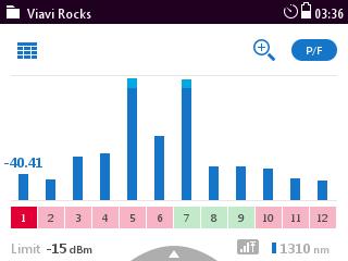
61 Network MPO OTDR Test 2 30 meters 3 SC/APC 20 meters 20 meters Launch SC/APC MPO12/APC 1 4 MPO12/APC MPO12/APC Receive 2017 EXFO Inc. All rights reserved. 6 1

62 MPO Cable 5 Fiber 2 has high Loss Fiber 8 has high loss & Reflectance Fiber 9 has high Loss


63 MPO Fiber Inspection Fiber Inspection Probe X400 Magnification MPO FIP Tip MPO Bulkhead Inspection MPO Cable/fiber Inspection Capture/Analysis Software MPO Cleaning Tools
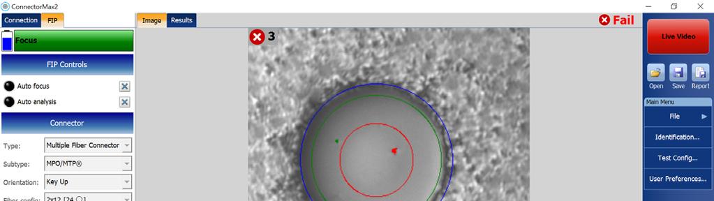


64 MPO Inspection Criteria Capture/Analysis Software

 -")

 - Fail")
65 iolm Trace MPO Cable 5- Fiber 8 Fiber 8 MPO(Unpinned) - Pass 9 8 MPO_5_08 Fails Reflectance Fibers 8,9 MPO(Pinned) - Fail 2017 EXFO Inc. All rights reserved. 65


66 MPO-SMF OTDR/Switch Test Case Fiber 9 MPO(U), after wet /dry 9 8 Fiber 8-9 MPO(P), after wet /dry

67 Cloud Based Test Management Remote Control Run Tests Remotely Shared application specific test licenses Test Data Manager Test Results Uploaded Test Configurations & Test Plans Downloaded Test Equipment Manager SW Revision Control Inventory Control

68 Jamie Humphreys EXFO
Trends in Testing Data Center Infrastructure. Ed Gastle VIAVI Solutions
 Trends in Testing Data Center Infrastructure Ed Gastle VIAVI Solutions Agenda INTRODUCTION Modern Data Center Architecture Historically Enterprise has been a 3 tier topology Core, Aggregation, Access Cloud
Insuring 40/100G Performance Multimode Fiber Bandwidth Testing & Array Solutions. Kevin Paschal Sr. Product Manager Enterprise Fiber Solutions
 Insuring 40/100G Performance Multimode Fiber Bandwidth Testing & Array Solutions Kevin Paschal Sr. Product Manager Enterprise Fiber Solutions Fiber Optics LAN Section Part of the Telecommunications Industry
Testing Parallel Optics
 White Paper Testing Parallel Optics Author: Ed Gastle VIAVI Solutions To accommodate the relentless need for speed, driven by mobile devices, watching videos online and uploading and sharing content, network
PARALLEL OPTICS CLEANING AND TESTING JANUARY 2018 FOR PROFESSIONALS MANAGING THE CABLE AND WIRELESS SYSTEMS THAT ENABLE CRITICAL COMMUNICATIONS DESIGN
 JANUARY 2018 FOR PROFESSIONALS MANAGING THE CABLE AND WIRELESS SYSTEMS THAT ENABLE CRITICAL COMMUNICATIONS CLEANING AND TESTING PARALLEL OPTICS DESIGN PAGE 5 Single pair Ethernet: Data and power DATA CENTER
Fiber in Data Centers What s Next? Srinivasan B, RCDD
 Fiber in Data Centers What s Next? Srinivasan B, RCDD Hubbell Fiber Systems 10G / 40G / 100G / 400G Standards, Applications and Practices Agenda Part 1: Current Technologies Standards Review IEEE 802.3:
Fiber Optic Cabling Systems for High Performance Applications
 Fiber Optic Cabling Systems for High Performance Applications BICSI Conference Bangkok, Thailand 17-18 November 2016 Nicholas Yeo, RCDD/NTS/DCDC Data Center Trends Computing evolution Cloud computing Servers
Data Center: First-Time Right Acceptance Testing Steps for Certification and Troubleshooting - Intra & Inter-connect. Nicholas Gagnon EXFO
 Data Center: First-Time Right Acceptance Testing Steps for Certification and Troubleshooting - Intra & Inter-connect Nicholas Gagnon EXFO Data Center today Source: EXFO Global Data Center Traffic by Destination
Common Mistakes Made in Certification Specifications and Testing. Jim Davis Regional Marketing Engineer Fluke Networks
 Common Mistakes Made in Certification Specifications and Testing Jim Davis Regional Marketing Engineer Fluke Networks Common Mistake #1 Failing to specify a Permanent Link test #1 Permanent Link or Channel?
The Fiber Formula Fact, Fiction & Fantasy Rodney Casteel, RCDD, DCDC, NTS, OSP - CommScope, Chair TIA FOTC Paul Neveux, Jr., Ph.D.
 The Fiber Formula Fact, Fiction & Fantasy Rodney Casteel, RCDD, DCDC, NTS, OSP - CommScope, Chair TIA FOTC Paul Neveux, Jr., Ph.D. - Superior Essex International, LP Tony Irujo, OFS David Asta, RCDD, Panduit
Choosing MPO Connectors for the Data Center. Ken Hall, RCDD, NTS Data Center Architect CommScope
 Choosing MPO Connectors for the Data Center Ken Hall, RCDD, NTS Data Center Architect CommScope Agenda Network Architecture changes Data Center & MPO Standards Application comparisons Additional considerations
Testing Considerations for Beyond 10Gigabit Ethernet. Erin Hallett
 Testing Considerations for Beyond 10Gigabit Ethernet Erin Hallett JDSU Agenda Intro Need for Speed Growth of IP traffic Fiber vs. Copper Fiber Tightening requirements Testing considerations and practices
Advances in Fiber Tier 2 Enterprise & Data Center Testing
 Advances in Fiber Tier 2 Enterprise & Data Center Testing As the volume of fibers deployed into enterprise increases significantly, fiber cabling advances like multi-fiber (MPO) connectors and interfaces
Overcoming the Testing Challenges of 40G and Beyond. Eric Farst Channel Sales Manager
 Overcoming the Testing Challenges of 40G and Beyond Eric Farst Channel Sales Manager Agenda Introduction Increased demand for speed & capacity in the Enterprise/Data Center How Enterprises/Data Centers
Are Conflicts in Data Center Fiber Optic Structured Cabling Standards Putting Your Organization at Risk?
 Are Conflicts in Data Center Fiber Optic Structured Cabling Standards Putting Your Organization at Risk? Rick Dallmann Senior Data Center Infrastructure Architect CABLExpress 36 Years of Experience CABLExpress
A Fork in the Road OM5 vs. Single-Mode in the Data Center. Gary Bernstein, Sr. Director, Product Management, Network Solutions
 A Fork in the Road OM5 vs. Single-Mode in the Data Center Gary Bernstein, Sr. Director, Product Management, Network Solutions Outline Definition of Enterprise and Cloud Data Centers The Growth of Cloud
Multimode Measurement Cords Recommendations for Multimode Link Field Certification
 Multimode Measurement Cords Recommendations for Multimode Link Field Certification FiberXpert OTDR 1 BACKGROUND Different Multimode Cable Categories Multimode cables are at current categorised into 4 different
Presenter: Roland Schlehuber. Fluke Networks
 Fiber optic theory and testing Presenter: Roland Schlehuber NE Distribution Sales Manager Fluke Networks Agenda Trends and Performance Requirements in Fiber optics Fiber Inspection and Cleaning Tier 1
Optical Fiber for Today s Premises Applications
 Optical Fiber for Today s Premises Applications Tony Irujo Customer Technical Support Mgr. OFS Optical Fiber Division 508-347-8582 tirujo@ofsoptics.com 1 Copyright 2006 Fitel USA Corp., All rights reserved.
Optical Fiber Networks: Industry. and New Options for Networks
 Optical Fiber Networks: Industry Trends, Application Influences and New Options for Networks Herbert V Congdon II, PE Manager, Standards & Technology Tyco Electronics AMP NETCONNECT Solutions Preview Deciding
The Impact of Emerging Data Rates on Layer One Fiber Cabling Infrastructures. Rick Dallmann Senior Data Center Infrastructure Architect CABLExpress
 The Impact of Emerging Data Rates on Layer One Fiber Cabling Infrastructures Rick Dallmann Senior Data Center Infrastructure Architect CABLExpress 36 Years of Experience CABLExpress is a manufacturer of
MTP/MPO Cable Assemblies
 MTP/MPO Cable Assemblies MTP cable assemblies are multi-fiber patch cords suitable for high-density back plane and PCB solutions. MTP brand Fan-Out, Interconnect and Trunk cable offer up to 36 times the
Leaders in the Advancement of Multimode Fiber. Fiber Future and Beyond
 Leaders in the Advancement of Multimode Fiber Fiber Future and Beyond Major Milestones in the Advancement of Multimode Fiber (MMF) Transmission OM4 Signature Core Fiber Cabling TIA WBMMF ISO/IEC OM5 (WBMMF)
100G SWDM4 MSA Technical Specifications Optical Specifications
 100G SWDM4 MSA Technical Specifications Specifications Participants Editor David Lewis, LUMENTUM The following companies were members of the SWDM MSA at the release of this specification: Company Commscope
Fiber Backbone Cabling in Buildings
 White Paper Fiber Backbone Cabling in Buildings www.commscope.com Contents Introduction 3 Backbone Cabling Speeds 3 Optical Fiber in the Backbone 4 b/s Optical Fiber Backbone 4 Migrating to 40 Gbps and
Optical Trends in the Data Center. Doug Coleman Manager, Technology & Standards Distinguished Associate Corning Optical Communications
 Optical Trends in the Data Center Doug Coleman Manager, Technology & Standards Distinguished Associate Corning Optical Communications Telecom 2017 Corning Restricted Incorporated 2 Server Access Switch
Copper Cabling from 10G to 400G, and back down to 10Mbps, but on 1 pair only
 1 Copper Cabling from 10G to 400G, and back down to 10Mbps, but on 1 pair only Gautier Humbert, RCDD Standards Coordinator Digital Infrastructures Legrand District Chair Mainland Europe BICSI 2 Agenda
Intra-DC & DCI considerations for 100G+ migration
 Intra-DC & DCI considerations for 100G+ migration Nicholas Gagnon, BDM Data Center NANOG 68 Dallas - October 18 th, 2016 2015 EXFO Inc. All rights reserved. 1 10G/40G to 100G/200G/400G Migration 2 DC global
DC Network Connectivity
 DC Network Connectivity Options & Optimizing TCO Rakesh SAMBARAJU - Application Engineer Nexans Data Center Solutions Agenda l Part I Ethernet Standards and Technologies Ø Current Ethernet Standards Ø
Test Equipment Depot Washington Street Melrose, MA TestEquipmentDepot.com. FiberTEK III
 Test Equipment Depot - 800.517.8431-99 Washington Street Melrose, MA 02176 - TestEquipmentDepot.com FiberTEK III User Manual Page 1 COPYRIGHT NOTICE The information contained in this document is the property
THE FABULOUS, FAST MOVING, FEVER PITCH, FOREVER ACCELERATING FIBER FRENZY Rodney Casteel, RCDD, DCDC, NTS, OSP - CommScope, Chair TIA FOTC Cindy
 THE FABULOUS, FAST MOVING, FEVER PITCH, FOREVER ACCELERATING FIBER FRENZY Rodney Casteel, RCDD, DCDC, NTS, OSP - CommScope, Chair TIA FOTC Cindy Montstream, EE, RCDD, NTS, CPLP - Legrand, Standards Chair
Enterprise Network Test Strategies for Network Availability and Performance. A Sitaramaiah Director Fluke Networks India
 Enterprise Network Test Strategies for Network Availability and Performance A Sitaramaiah Director Fluke Networks India 1 Why is Enterprise Network Testing becoming increasingly important? IT is increasingly
Tim Takala RCDD. Vice President Field Application Engineer APAC. Mobility is Driving Changing Network Architectures & Transceiver Evolutions
 Tim Takala RCDD Vice President Field Application Engineer APAC Mobility is Driving Changing Network Architectures & Transceiver Evolutions 5TOP TRENDS SHAPING NETWORKS 1. Mobility 2. Connected Devices
Data Center & Cloud Computing Infrastruture Solutions DATASHEET. Standard Fiber Patch Cable. Make high-speed Ethernet network equipment connections
 Data Center & Cloud Computing Infrastruture Solutions DATASHEET Standard Fiber Patch Cable Make high-speed Ethernet network equipment connections 1 Description Fiber optic patch cables are ideal for supporting
ExtremeSwitching TM. 100Gb Ethernet QSFP28 Transceivers and Cables. Product Overview. Data Sheet. Highlights. 100Gb Ethernet QSFP28 SR4 MMF
 Data Sheet Highlights Compact Quad Small Form-factor Pluggable (QSFP28) products for high density 100Gb Ethernet applications Hot swappable, field serviceable modular interfaces for Extreme Networks switches
Wideband Multimode Fiber What is it and why does it make sense?
 White Paper Wideband Multimode Fiber What is it and why does it make sense? March, 2015 Contents Executive summary 3 A brief history of MMF 3 The role of fiber connectors 4 Introducing WBMMF 5 2 Executive
Fiber backbone cabling in buildings
 White paper Fiber backbone cabling in buildings www.commscope.com 1 Contents Introduction 3 Backbone cabling speeds 3 Optical fiber in the backbone 3 10 Gbps optical fiber backbone 3 Migrating to 40 Gbps
How to Decide on Optical Fibre Termination Options. Thomas Ko, RCDD Product Manager Tyco Electronics / AMP NetConnect
 How to Decide on Optical Fibre Termination Options Thomas Ko, RCDD Product Manager Tyco Electronics / AMP NetConnect Termination Choices Optical Fiber Cabling in Data Center Options available Traditional
Opt-X Enterprise Fiber Trunk Cables
 APPLICATION Factory-terminated and tested fiber trunk cables connect central patching locations to zones or pods. Available terminated with both modular (MTP ) and discrete connectors, these trunks are
Cisco 100GBASE QSFP-100G Modules
 Data Sheet Cisco 100GBASE QSFP-100G Modules Product Overview The Cisco 100GBASE Quad Small Form-Factor Pluggable (QSFP) portfolio offers customers a wide variety of high-density and low-power 100 Gigabit
Optical Certifier I. Tier-1 Fibre Certifier for Multimode and Single-mode Fibre Cabling. Proof of Performance
 Optical Certifier I Tier-1 Fibre Certifier for Multimode and Single-mode Fibre Cabling Proof of Performance Optical Certifier I Tier-1 Fibre Certifier for Multimode and Single-mode fibre cabling The Optical
White Paper: Testing Strategies for SYSTIMAX High Speed Migration Solutions
 White Paper: Testing Strategies for SYSTIMAX High Speed Migration Solutions Exploding demand for bandwidth is pushing data center teams to rethink their network infrastructure as they look to support faster
User Manual Fiber Certification Testing
 User Manual Fiber Certification Testing User Manual Fiber Certification, WireXpert v7.1.0, build #276 WireXpert4500_Fiber_IT_EN_U_201511_102S Copyrights 2015 Softing Inc. http://itnetworks.softing.com/
History of Standards
 History of Standards From 10Mbps to 100Gbps Ethernet 12 th May 2014 Gautier Humbert, RCDD Business Development Manager Legrand East and Central Europe Agenda 1- Current standards and their structures
Using Low DMD, Laser Optimized Multimode Fiber to Expand 10-Gigabit Network Design Options
 Using Low DMD, Laser Optimized Multimode Fiber to Expand 10-Gigabit Network Design Options Lisa Huff Technical Manager, Advanced Design & Applications Berk-Tek, a Nexans Company Adam Murano Fiber Engineering
Standards Update. Mylaraiah J N, RCDD Member, BICSI India Steering Committee
 Standards Update Mylaraiah J N, RCDD Member, BICSI India Steering Committee Standards Update International Standards Interrelations Reference Guide Standard ISO/IEC CENELEC TIA/EIA Performance / Generic
Factory assembled FO cabling system with LC-Duplex adapter-interfaces in PURE quality, GHMT channel certified
 Factory assembled FO cabling system with LC-Duplex adapter-interfaces in PURE quality, GHMT channel certified Our motivation for the development of is the requirement of today`s high performance transmission
SUMITOMO SPECIFICATION. FutureFLEX. Multimode 62.5 µm Core Optical Fiber (OM1) Gigabit Grade
 Gigabit Grade") SUMITOMO SPECIFICATION FutureFLEX Multimode 62.5 µm Core Optical Fiber (OM1) Gigabit Grade SUMITOMO ELECTRIC LIGHTWAVE CORP. 201 South Rogers Lane, Suite 100, Raleigh, NC 27610 (919) 541-8100 or 1-800-358-7378
SUMITOMO SPECIFICATION FutureFLEX Multimode 62.5 µm Core Optical Fiber (OM1) Gigabit Grade SUMITOMO ELECTRIC LIGHTWAVE CORP. 201 South Rogers Lane, Suite 100, Raleigh, NC 27610 (919) 541-8100 or 1-800-358-7378
Data Center & Cloud Computing Infrastruture Solutions DATASHEET. MTP/MPO-LC Breakout Cable Aseemblies High Density Cabling System
 Data Center & Cloud Computing Infrastruture Solutions DATASHEET MTP/MPO-LC Breakout Cable Aseemblies High Density Cabling System REV.2.0 2018 MTP/MPO Breakout Cable 01 Description MTP/MPO breakout assemblies
HIGH DENSITY DATA CENTER CABLING GUIDE. Optics DACs Cables Cable Management Fiber TAPs Media Converters
 HIGH DENSITY DATA CENTER CABLING GUIDE Optics DACs Cables Cable Management Fiber TAPs Media Converters PROVIDING MTP CABLING SOLUTIONS FOR THE SMART DATA CENTER. APPROVED NETWORKS SETS THE STANDARD The
Optics Modules and Cables Data Sheet
 Optics Modules and Cables Data Sheet Key Features Deployment flexibility of 100GbE, 40GbE, 25GbE, 10GbE or 1GbE modules Smallest and lowest power SFP optic module form factor for 1GbE, 10GbE and 25GbE
Physical Layer changes coming to a network near you, soon! Wayne Allen Regional Marketing Engineer Fluke Networks
 Physical Layer changes coming to a network near you, soon! Wayne Allen Regional Marketing Engineer Fluke Networks Agenda New ISO/IEC 11801 Standard New Fibre standards and encoding methods Higher speeds,
MTP Multi Lite Trunk Assemblies
 MTP Multi Lite Trunk Assemblies MTP Multi-Lite Trunk assemblies are a neat solution for providing up to four MTP -MTP links within a compact, high density ruggedised cable. The cable construction consists
MTP Cabling Overview. MTP Cabling System
 MTP cabling architectures utilise varying cable and patchcord configurations as defined in TIA-568-C.0-2. These cables vary by gender, fibre orientation and pair management. AFL manufactures a large and
Dell Networking Optics and Cables Connectivity Guide
 Dell Networking and Cables Connectivity Guide 1 Gigabit Ethernet (1GbE) 10 Gigabit Ethernet (10GbE) 40 Gigabit Ethernet (40GbE) 100 Gigabit Ethernet (100GbE) Fibre Channel Networking I/O Connectivity Options
RIFOCS Corp. Component Services Division
 RIFOCS Corp. Component Services Division Overview The Components Division is one of four business units within RIFOCS Corporation. The other three divisions are Instruments, Harsh Environments, and International.
THE NEW OPTICAL FIBRE CATEGORIES What do they promise?
 THE NEW OPTICAL FIBRE CATEGORIES What do they promise? prepared and delivered by ϕ Breakfast Seminar 13th March 2001 Fibreoptic Industry Association PO Box MT65 LEEDS LS17 8YD UK Tel: +44 (0) 113 232 3721
Datasheet: FI-500 FiberInspector Micro-Fiber Optic Endface Inspection Scope with PortBright Illumination.
 Datasheet: FI-500 FiberInspector Micro-Fiber Optic Endface Inspection Scope with PortBright Illumination. Datasheet: FI-500 FiberInspector Micro-Fiber Optic Endface Inspection Scope with PortBright Illumination.
LAN Standards, News & Trends Update 2017 June 15, 2017
 LAN Standards, News & Trends Update 2017 June 15, 2017 Greg Olson Jtech Systems, Inc Infrastructure Specialist Greg@jtechreps.com 425-437-1962 Our Objectives Review new & ongoing applications work in IEEE
Data center applications standards reference guide
 White paper Data center applications standards reference guide Networking and storage Contents Scope 3 Introduction 3 Data center cabling standard ISO/IEC 24764 3 Ethernet (IEEE 802.3) 4 Proprietary 40
ConnectorMax MPO Link Test Solution A COMPLETE MPO POLARITY, CONTINUITY AND CONNECTOR INSPECTION SOLUTION FOR SHORT FIBER LINKS (UP TO 5 KM)
") A COMPLETE MPO POLARITY, CONTINUITY AND CONNECTOR INSPECTION SOLUTION FOR SHORT FIBER LINKS (UP TO 5 KM) All-in-one, easy-to-use solution to validate the polarity type, continuity and connector cleanliness
A COMPLETE MPO POLARITY, CONTINUITY AND CONNECTOR INSPECTION SOLUTION FOR SHORT FIBER LINKS (UP TO 5 KM) All-in-one, easy-to-use solution to validate the polarity type, continuity and connector cleanliness
AMENDED FINAL REPORT FOR:
 731 Enterprise Drive Lexington, KY 40510 Telephone: 859-226-1000 Facsimile: 859-226-1040 www.intertek-etlsemko.com AMENDED FINAL REPORT FOR: CUSTOMER NAME: PRODUCT NAME: Leviton 2222 222nd St. SE Bothell,
OTS-600 Series Optical Sources, Meters, Testers and Kits with Data Storage Capabilities
 features and benefits Large LCD screen and soft key menus Source and meter in one unit Auto wavelength switching and detection USB data ports OTS-600 Series Light Source and Power Meter Photo LAN1193 Ease
Cisco 100GBASE QSFP-100G Modules
 Data Sheet Cisco 100GBASE QSFP-100G Modules Product Overview The Cisco 100GBASE Quad Small Form-Factor Pluggable (QSFP) portfolio offers customers a wide variety of high-density and low-power 100 Gigabit
FTTE Revisited for New Technologies
 FTTE Revisited for New Technologies A new look into FTTE design to allow great flexibility as well as compliance to the latest 40G and 100G. Gautier Humbert, RCDD, CDCDP Business Development Manager Eastern
High Speed Migration: Choosing the right multimode multi-fiber push on (MPO) system for your data center
 system for your data center") High Speed Migration: Choosing the right multimode multi-fiber push on (MPO) system for your data center Table of Contents Introduction 3 Figure 1 - The Ethernet road map 3 Planning considerations 4 Fiber
High Speed Migration: Choosing the right multimode multi-fiber push on (MPO) system for your data center Table of Contents Introduction 3 Figure 1 - The Ethernet road map 3 Planning considerations 4 Fiber
Polymer Coated Fiber Cable (PCF)
") Polymer Coated Fiber Cable (PCF) Panduit has introduced a Polymer Coated Fiber (PCF) to their fiber cable offering available in 50µm and 62.5µm core diameters. Along with this cable having a stronger durability
Polymer Coated Fiber Cable (PCF) Panduit has introduced a Polymer Coated Fiber (PCF) to their fiber cable offering available in 50µm and 62.5µm core diameters. Along with this cable having a stronger durability
Pre-terminated Multi Fibre Cable Assemblies
 AFL manufactures a broad range of factory terminated and tested multi-fibre cable assemblies. These assemblies are available in various fibre types and counts, cable constructions and connector options.
Adrian Young Leviton Network Solutions
 Adrian Young Leviton Network Solutions In This Session Multimode fiber types How many fibers do I need for my application? Future IEEE and non IEEE applications Will my existing fiber plant support these?
WIREXPERT FIBER LOSS TEST KIT TECHNICAL REFERENCE MANUAL. WireXpert Fiber Loss Test Kit Technical Reference Manual
 WireXpert Fiber Loss Test Kit Technical Reference Manual i Table of Contents Introduction... 1 Package Contents... 1 Single-mode Certification Kit... 1 Multi-mode Certification Kit... 1 Features and Benefits...
Testing Optical Feeds in Wireless Systems Remote Radio Units (RRU) and Distributed Antenna Systems (DAS)
 and Distributed Antenna Systems (DAS)") Application Note Testing Optical Feeds in Wireless Systems Remote Radio Units (RRU) and Distributed Antenna Systems (DAS) MT9090A/MU909011A Network Master Optical Fault Locator (OTDR) By Stephen Colangelo
Application Note Testing Optical Feeds in Wireless Systems Remote Radio Units (RRU) and Distributed Antenna Systems (DAS) MT9090A/MU909011A Network Master Optical Fault Locator (OTDR) By Stephen Colangelo
Cisco 40GBASE QSFP Modules
 Data Sheet Cisco 40GBASE QSFP Modules Product Overview The Cisco 40GBASE QSFP (Quad Small Form-Factor Pluggable) portfolio offers customers a wide variety of high-density and low-power 40 Gigabit Ethernet
OPTICAL CONNECTOR CONTAMINATION
 OPTICAL CONNECTOR CONTAMINATION 6 What do the standards say? The test procedures specified by 568-C require tools and procedures for ensuring connector quality. End faces on cords and trunks shall be in
MaxTester 940 Fiber Certifier OLTS OPTIMIZED FOR DATA-CENTER AND ENTERPRISE TIER-1 FIBER CERTIFICATION
 OPTIMIZED FOR DATA-CENTER AND ENTERPRISE TIER-1 FIBER CERTIFICATION Fully featured tier-1 fiber certifier with tablet-inspired design. Minimized learning curve. Optimized clear, fast and first-time-right
AMENDED FINAL REPORT FOR:
 731 Enterprise Drive Lexington, KY 40510 Telephone: 859-226-1000 Facsimile: 859-226-1040 www.intertek.com AMENDED FINAL REPORT FOR: CUSTOMER NAME: PRODUCT NAME: Leviton Manufacturing Co. 417 Stone Drive
MaxTester 945 OLTS KEY FEATURES APPLICATIONS COMPLEMENTARY PRODUCTS SPEC SHEET
 FULLY AUTOMATED FASTEST TM BIDIRECTIONAL INSERTION LOSS, ORL AND LENGTH MEASUREMENT ANALYSIS SOFTWARE First tablet-inspired multifunction optical loss test set (OLTS) delivering insertion loss (IL), optical
Field Testing Installed Optical Fiber Cabling. Field Testing Installed Optical Fiber Cabling JUNE 2010 WHITE PAPER JUNE 2010
 JUNE 2010 Field Testing Installed Optical Fiber Cabling 1 BY: JAY PAUL MYERS, RCDD TECHNICAL TRAINING SPECIALIST LEGRAND ORTRONICS BY: JASON TARN PRODUCT MARKETING MANAGER FLUKE NETWORKS 2 This joint white
PREPARING FOR FUTURE STRUCTURED CABLING REQUIREMENTS IN THE DATA CENTER: 40/100 GIGABIT ETHERNET AND BEYOND
 PREPARING FOR FUTURE STRUCTURED CABLING REQUIREMENTS IN THE DATA CENTER: 40/100 GIGABIT ETHERNET AND BEYOND Cindy Montstream, RCDD/NTS, EE, CPLP Director of elearning and Standards DATA COMMUNICATIONS
The Arista Universal transceiver is the first of its kind 40G transceiver that aims at addressing several challenges faced by today s data centers.
 ARISTA WHITE PAPER QSFP-40G Universal Transceiver The Arista Universal transceiver is the first of its kind 40G transceiver that aims at addressing several challenges faced by today s data centers. Increased
MTP Outdoor Cabling System
 The AFL MTPE (MTP Elite) Low Loss outdoor cabling system offers a market leading, low loss, fast and efficient connection system for underground (UG) and outside plant applications. These assemblies offer
Optical Trends in the Data Center
 Optical Trends in the Data Center Romeo Lazar Sales Manager, Eastern Europe Corning Optical Communications EMEA September 2016 Agenda Agenda Corning overview Data Center Server and Switch Trends Standards
Using Laser-Optimized Multimode Fiber for 1 and 10 Gigabit Campus Backbone Applications
 Using Laser-Optimized Multimode Fiber for 1 and 10 Gigabit Campus Backbone Applications David Kozischek, Market Manager Enterprise Networks, Corning Optical Communications Systems engineers at Corning
MTP/MPO SOLUTIONS FIBERTRONICS. General Applications & Loss Specifications
 MTP/MPO SOLUTIONS FIBERTRONICS Multifiber Push-On (MPO) connectors have answered the call for more bandwidth and more space efficiency. MPO connectors are able to provide up to 24 or more fibers in a single
Transceiver Fiber Inspection and Cleaning
 Application Note Transceiver Fiber Inspection and Cleaning VIAVI Solutions Introduction This document provides basic overview and background information for transceiver types that are commonly used in
MaxTester 940/945 Fiber Certifier OLTS OPTIMIZED FOR DATA CENTER AND ENTERPRISE TIER-1 FIBER CERTIFICATION
 OPTIMIZED FOR DATA CENTER AND ENTERPRISE TIER-1 FIBER CERTIFICATION Fully featured tier-1 fiber certifier with a tablet-inspired design and short learning curve. Optimized, clear and fast first-time-right
Cisco 10GBASE SFP+ Modules
 Data Sheet Cisco 10GBASE SFP+ Modules Product Overview The Cisco 10GBASE SFP+ modules (Figure 1) offer customers a wide variety of 10 Gigabit Ethernet connectivity options for data center, enterprise wiring
Next-gen 400 and 200 Gb/s PHYs over Fewer MMF Pairs Call For Interest Consensus Presentation. IEEE Draft 0.3
 Next-gen 400 and 200 Gb/s PHYs over Fewer MMF Pairs Call For Interest Consensus Presentation IEEE 802.3 Draft 0.3 Agenda Overview Discussion Presenter 1 Presentations Market Drivers Presenter 2 Technical
Complete Tier 1 and Tier 2 test solutions. Fiber test tools catalogue
 Complete Tier 1 and Tier 2 test solutions Fiber test tools catalogue Complete Tier 1 and Tier 2 test solutions Fiber test tools catalogue EXFO is a global leader in telecom test and measurement solutions.
Sumitomo Fiber Specification SE-7** Non-Zero Dispersion Shifted Single-Mode Fiber. PureMetro SM Optical Fiber, TIA Type Ivd, ITU-T G.
 Sumitomo Fiber Specification SE-7** Non-Zero Dispersion Shifted Single-Mode Fiber PureMetro SM Optical Fiber, TIA Type Ivd, ITU-T G.655 Issued: January 2006 CONTENTS 78 Alexander Drive, Research Triangle
Arista 400G Transceivers and Cables: Q&A
 Arista 400G Transceivers and Cables: Q&A What are the benefits of moving to 400G technology? 400G Transceivers and Cables Q&A Arista s 400G platforms allow data centers and high-performance computing environments
Cisco 10GBASE SFP+ Modules
 Cisco 10GBASE SFP+ Modules Product Overview The Cisco 10GBASE SFP+ modules (Figure 1) offer customers a wide variety of 10 Gigabit Ethernet connectivity options for data center, enterprise wiring closet,
Qualified Partner Programme QPP. Fiber Optic Gigabit Ethernet Theory Felice Guarna
 Qualified Partner Programme QPP Fiber Optic Gigabit Ethernet Theory Felice Guarna Applications The protocols used in LAN mostly base on Ethernet technology. In 1998 the IEEE 802.3z was passed (Gigabit
MT-RJ OPTICAL FIBER SYSTEMS TESTING. Field Testing Made Easy
 MT-RJ OPTICL FIER SYSTEMS TESTING Field Testing Made Easy TLE of CONTENTS Introduction...3 Recommended Test Components...4 Testing With Dual Sources and Detectors...5 Testing with a One Port Test Set...9
Optical Fiber Premises Standards News & Trends
 1 Optical Fiber Premises Standards News & Trends Herb Congdon Tyco Electronics Updated: October 2005 hvcongdon@tycoelectronics.com 2 IEEE Ten Gigabit Ethernet (10GBASE-F) Published as IEEE802.3ae in June
PARKING. JDSU Solutions for Enterprise Structured Cabling
 COMMUNICATIONS TEST AND MEASUREMENT SOLUTIONS JDSU Solutions for Enterprise Structured Cabling JDSU offers a complete range of communications test and measurement solutions to address the needs of cabling
MaxTester 940/945 OLTS FULLY AUTOMATED FASTEST BIDIRECTIONAL MEASUREMENTS FOR INSERTION LOSS, OPTICAL RETURN LOSS AND FIBER LENGTH
 MaxTester 940/945 OLTS FULLY AUTOMATED FASTEST BIDIRECTIONAL MEASUREMENTS FOR INSERTION LOSS, OPTICAL RETURN LOSS AND FIBER LENGTH ANALYSIS SOFTWARE First tablet-inspired multifunction optical loss test
NGBASE-T Cabling Requirements
 NGBASE-T Cabling Requirements Dr. T. C. Tan, DMTS, CommScope Labs B.Sc (Eng), DIC, PhD, CEng, FIET White paper www.commscope.com Contents Contents Contents 2 1.0 Introduction 3 2.0 IEEE 802.3 NGBASE-T
Pretium EDGE HD Solutions A LANscape Pretium Solutions Product
 Pretium EDGE HD Solutions for Enterprise Data Centers and Storage Area Networks Corning Pretium EDGE HD solutions create a fiber optic tip-to-tip solution for data centers and storage area networks (SANs)
DATA CENTER SYMPOSIUM
 DATA CENTER SYMPOSIUM Dynamic Changes in Data Center Optic Transmissions & The Impact to Structured Fiber Cabling Rick Dallmann CABLExpress Years of Experience CABLExpress is a manufacturer of custom built
AMENDED FINAL REPORT FOR:
 731 Enterprise Drive Lexington, KY 40510 Telephone: 859-226-1000 Facsimile: 859-226-1040 www.intertek.com AMENDED FINAL REPORT FOR: CUSTOMER NAME: Leviton Manufacturing Co. 417 Stone Drive St. Charles,
High Speed Migration 100G & Beyond
 High Speed Migration 100G & Beyond Moses Ngugi Field Application Engineer 5th September 2017 BANDWIDTH GROWTH Mobile Data IP Video Global Cloud IP Traffic Global IP Traffic Cisco CAGR: 50+% CAGR: 35%+