HARTING. News People Power Partnership
|
|
|
- Meghan Angelica Tyler
- 5 years ago
- Views:
Transcription


1 HARTING News 2008 People Power Partnership


2 Quality Connections Worldwide HARTING was founded in 1945 by the family that still owns the company. Its headquarters are situated in Espelkamp, in Eastern Westphalia. Today, HARTING employs approximate 3,000 people worldwide, including 300 engineers and scientists. Over 500 technical specialists are available to implement customer requirements. With subsidiaries in 27 countries and ten production plants, the company is one of the leading manufacturers of electrical and electronic connectors. The global HARTING network means that the company is always in close touch with the market and ideally placed to work together with its customers. As the market leader HARTING offers the benefits of just-in-time service and maintains close business relations with all of its key customers in the global marketplace. In more than one of its product areas, HARTING leads the field. HARTING products are manufactured using advanced, automated techniques, with CAD systems employed both in research and development and in tool-making. In matters of quality, HARTING is convinced that zero-defect production can only be achieved through fully automated processes. Our quality assurance organization and procedures are documented in accordance with EN ISO 9001 in a quality assurance manual. In 2006 HARTING became the first company worldwide to receive the new IRIS quality certificate (the International Railway Industry Standard). HARTING employs around 60 staff in quality assurance alone. The majority of these engineers and technicians are trained and qualified to standards laid down by the DGQ (German Association of Quality) or SAQ (Swiss Association of Quality).
3 HARTING News Contents Seite Industrial Connectors Han 4 A Quick Lock... 6 Han Q 5/0 Quick Lock... 7 Han-Modular EE Module Quick Lock Han Q 12/ Han-Modular Compact M25 und M Han-Elisa Han-Power T Modular Twin Han 3 A Hood with integrated Cable Gland Han-INOX 3 A Han A Gasket Han 16 HPR Bulkhead mounted Housing with Cover Han Q 4/2 Inserts with PCB adapter Han Q 8/0 Inserts with PCB adapter Han PushPull Han PushPull Power 4/0 Metal Han PushPull Power 4/0 Plastic Han PushPull RJ45 Metal Han PushPull RJ45 Plastic Han PushPull SCRJ Metal Han PushPull SCRJ Plastic HARAX HARAX M8-S HARAX M8-S (0.8 mm²) HARAX M12-S HARAX M12-L Profibus HARAX M12 with HARAX IDC HARAX M12 with Crimp terminal Industrial Ethernet HARTING econ HARTING econ 2050-AA HARTING econ 2160-A HARTING econ 3000 Media converter HARTING econ 3011-AD HARTING econ 3011-ASFP
4 HARTING News Contents Seite HARTING scon Introduction HARTING scon HARTING scon 3061-AE HARTING scon 3063-AE HARTING scon 3082-AE HARTING scon 3061-AF HARTING scon 3082-AF HARTING mcon HARTING mcon 3061-AE HARTING mcon 3063-AE HARTING mcon 3082-AE HARTING mcon HARTING mcon 1052-AE HARTING mcon 1052-AE HARTING mcon 1061-AE HARTING mcon 1070-AE HARTING mcon 1082-AE HARTING mcon 1083-AE Accessories mcon HARTING pcon HARTING pcon HARTING pcon HARTING pcon HARTING pcon System cable Cat. 6 PVC System cable Cat. 6 PUR System cable Cat. 6 Outdoor Installation cable Cat. 6A System cable Cat. 5 PUR System cable with HARTING RJ Industrial on both sides System cable with HARTING PushPull on both sides System cable with HARTING PushPull to RJ45 (IP 20) System cable with Han 3 A to RJ45 (IP 20) System cable with Han PushPull on both sides Additional information about overmoulded system cables HARTING PushPull Hybrid Device side Connector System cable, overmoulded
5 HARTING News Contents Page Electronic Connectors D-Sub SMT board connectors D-Sub filter adapter har-link connectors and cable assemblies SEK male headers with straight press-in pins SEK pcb transition connectors, 2 rows SEK female cable connectors SEK male headers with straight solder pins, kinked TCA connectors General information AdvancedMC connectors for AdvancedTCA Power connectors for AdvancedTCA AdvancedMC connector for MicroTCA Power output connectors for MicroTCA Plug connectors for MicroTCA and AdvancedTCA Press-in tooling Signal integrity support Summary Catalogues Addresses


 Insulation resistance 10 10 Material Polycarbonate Flammability acc.")
6 Han 4 A Quick Lock Han-Quick Lock Features Innovative Han-Quick Lock termination technology Field assembly without special tools Compatible to Han 4 A standard inserts Reduced wiring times Insert suitable for all metal and plastic hoods and housings of the sizes Han 3 A Vibration resistant Technical characteristics Protection degree IP 65 / IP 67 Number of contacts 4 + PE Electrical data acc. to DIN EN A 230/400 V 4 kv 3 Rated current 10 A Rated voltage conductor-ground 230 V Rated voltage conductor-conductor 400 V Rated impulse voltage 4 kv Pollution degree 3 Termination Han-Quick Lock Wire gauge 0.5 bis 2.5 mm² (AWG 20 14) Insulation resistance Material Polycarbonate Flammability acc. to UL 94 V 0 Mechanical working life 500 mating cycles Han 4 A Quick Lock Male insert Female insert


 Insulation resistance 10 10 Material Polycarbonate Flammability acc.")
7 Han Q 5/0 Quick Lock Han-Quick Lock Features Innovative Han-Quick Lock termination technology Field assembly without special tools Compatible with Han Q 5/0 standard inserts Reduced wiring times Insert suitable for all metal and plastic hoods and housings of the sizes Han 3 A Vibration resistant Technical characteristics Protection degree IP 65 / IP 67 Number of contacts 5 + PE Electrical data acc. to DIN EN A 230/400 V 4 kv 3 Rated current 16 A Rated voltage conductor-ground 230 V Rated voltage conductor-conductor 400 V Rated impulse voltage 4 kv Pollution degree 3 Termination Han-Quick Lock Wire gauge 0.5 bis 2.5 mm² (AWG 20 14) Insulation resistance Material Polycarbonate Flammability acc. to UL 94 V 0 Mechanical working life 500 mating cycles Han Q 5/0 Quick Lock Male insert Female insert


8 Han EE Module Quick Lock Han-Quick Lock Samples available by November 2008 Features Innovative Han-Quick Lock termination technology Field assembly without special tools Compatible to standard Han EE module with crimp termination Reduced wiring times Technical characteristics Number of contacts 8 Electrical data acc. to DIN EN A 400 V 6 kv 3 Rated current 16 A Rated voltage 400 V Rated impulse voltage 6 kv Pollution degree 3 Termination Han-Quick Lock Wire gauge 0.5 bis 2.5 mm² (AWG 20 14) Insulation resistance Material Polycarbonate Flammability acc. to UL 94 V 0 Mechanical working life 500 mating cycles Bezeichnung Bestell-Nummer Zeichnung Maße in mm Han EE module Quick Lock Male insert Female insert
9 Notes 9


10 Han Q 12/0 Han-Quick Lock Number of contacts 12 + Inserts Part Number Han Q 12/ Coding pins order separately 1 unit à 20 pieces Wire gauge Part Number ² Male contacts Female contacts Dimensions in mm Han D crimp contacts silver plated gold plated mm² 0.5 mm² 0.75 mm² 1.0 mm² 1.5 mm² 2.5 mm² Wire gauge ø Stripping length AWG AWG 20 AWG 18 AWG 18 AWG 16 AWG mm 1.10 mm 1.30 mm 1.45 mm 1.75 mm 2.25 mm 8 mm 8 mm 8 mm 8 mm 8 mm 6 mm 10
11 Han Q 12/0 Features 12 contact chambers taking the control contacts of the series Han D with crimp termination 1 PE contact with innovative Han-Quick Lock termination technology 2 coding pins offering 16 coding possibilities Insert suitable for metal and plastic hoods and housings of the series Han 3 A Technical characteristics DIN VDE 0627 DIN VDE 0110 DIN EN Inserts Number of contacts 12 + PE Electrical data acc. to DIN EN A 400 V 6 kv 3 Rated current 10 A Rated voltage 400 V Rated impulse voltage 4 kv Pollution degree 3 Pollution degree 2 also 10 A 400/690 V 6 kv 2 Termination Han D contacts Crimp Termination PE contact Han-Quick Lock Wire gauge PE contact mm² AWG Insulation resistance Material Polycarbonate Limiting temperatures -40 C C Flammability acc. to UL 94 V 0 Mechanical working life 500 mating cycles Contacts Material Copper alloy Surface - hard silver plated 3 µm Ag - hard gold plated 2 µm Au over 3 µm Ni Contact resistance 3 m Crimp termination - mm² mm² - AWG Maximum insilation cross section - power contacts ø = 5 mm Plastic hoods/ housings Material Polycarbonate Locking element Polyamide Flammability acc. to UL 94 V 0 Hoods/ housings seal NBR Limiting temperatures -40 C C Degree of protection acc. to DIN EN in locked position IP 67 Metal hoods/ housings Material Die cast zinc alloy Locking element Steel galvanized Hoods/ housings seal NBR Limiting temperatures -40 C C Degree of protection acc. to DIN EN in locked position IP 44 IP 67 with sealing screw


12 Han-Modular Compact *Available by May 2008 Hoods and housings M25 and M32 Hood side entry M screws are included in delivery range Hood top entry M screws are included in delivery range Hood* top entry M32 screws are added separately screws are included in delivery range Carrier hood Protection cover with lever and seal Housing bulkhead mounting Panel cut out Protection cover
13 Han-Modular Compact Features Technical characteristics Hoods/Housings Material Zinc die-cast Surface Nickel plated Locking element Stainless steel Hoods/housings sealing NBR Limiting temperatures Degree of protection acc. to DIN EN for coupled connectors IP 65 Mechanical working life 500 mating cycles PE contact Wire gauge Stripping length 10 mm Tightening torque 1 Nm Protection covers Material Locking element Hoods/housings sealing NBR Limiting temperatures Degree of protection acc. to DIN EN for coupled connectors IP 65 Flammability acc. to UL 94 V 0 Current carrying capacity The current carrying capacity of the connectors is limited by the thermal load capability of the contact element material including the connections and the insulating parts. The derating intermittent) through each contact element of the connector evenly, without exceeding the allowed maximum temperature. Measuring and testing techniques acc. to DIN EN
 Economy of space by reduction the number of terminal blocks and interface modules in the switch cabinet General description The Han-Elisa -")

14 Han-Elisa Flexibles I/O system integrated inside the connector Features the connector Individual combination of input and output modules for optimal signal pre-processing Minimum size for integration in Han industrial connectors (Han-Modular and Han-Snap ) Economy of space by reduction the number of terminal blocks and interface modules in the switch cabinet General description The Han-Elisa - directly in the connector. The In- and Output modules are developed for 1 or 2 channels and can be combined variously and thin the product family modules are available for current/voltage conversion, temperature, relay and timer. Due to the minimized size these modules can be integrated into the Han-Modular and Han-Snap system. connector and this will reduce installation space for terminal blocks and the number of interface modules. So the switch cabinets can be made smaller. 14
15 Han-Elisa Ethernet Switch SmartCon General Technische technical Kennwerte characteristics Environmental conditions Operation -20 C C Storage -40 C C Mechanical data Dimensions (WxDxH) 30.3 x 53 x 14.7 mm Material Polycarbonate / LCP Mating face Input module: male Output module: female Degree of protection acc. to DIN IP 20 IP 65 within mated connector (e.g. Han B housing, high construction) Cage clamp terminal mm² Power supply (combination input and output module) Supply voltage 24 V (-10% %) Current consumption < 0.08 A Power consumption < 2 W Total transmission error < 0.2 % Product matrix and possible combinations of Han-Elisa modules Output modules Relay Optocoupler Input modules Different version Different versions Timing X X Output current ma galvanically isolated Output voltage V galvanically isolated Connecting 1:1 X X Temperature Pt100 Different temperature ranges Temperature thermo element type J, K Different temperature ranges Input current ma Input voltage V X = on request = available X X X X X X 15
 Economy of space by reduction the number of terminal blocks and interface modules in the switch")


16 Han-Elisa Available by August 2008 Pt100 Input module Features Minimum size for integration in Han industrial connectors (Han-Modular and Han-Snap ) Economy of space by reduction the number of terminal blocks and interface modules in the switch cabinet Male module for signal output Technical characteristics Sensor Pt100 acc. to IEC 751 Termination technology 2, 3, 4 wire technology Sensor input current 0.8 ma, constant Max. permissible conductor resistance 10 Min. measuring range 100 C Open circuit detection integrated Type of connection - cage clamp termination mm² Power diagnostic LED (green) Temperature module Pt100 Measuring range: C C additional measuring ranges on request Input 16
")

 Load I out < 500 Load U out 10 k Residual ripple < 20 mv (500 )")
 < 30 ms Type of connection - cage clamp termination 0.14-1.")

17 Han-Elisa Available by August 2008 Output module Features Minimum size for integration in Han industrial connectors (Han-Modular and Han-Snap ) Economy of space by reduction the number of terminal blocks and interface modules in the switch cabinet Female module for signal input Technical characteristics Supply voltage 24 V DC (-10 % %) Load I out < 500 Load U out 10 k Residual ripple < 20 mv (500 ) Step response ( %) < 30 ms Type of connection - cage clamp termination mm² Power diagnostic LED (green) Output module, current galvanically isolated Output signal ma Output Output module, voltage galvanically isolated Output signal V Output Additional output signals on request 17


18 Han-Power T Modular Twin Samples available by September 2008 with Han-Modular Twin Part-Number: Features Han-Power T 1 connection for power input and output each 1 T-connection to device 3 power contacts 5 signal contacts Metal hood Locking lever Han-Easy Lock Han-Modular Twin Hoods Dimensions in mm Technical characteristics Han-Power T Modular Twin hood Rated voltage 400 V Rated current 40 A Number of contacts 3 power contacts + PE max. 6 mm² 5 signal contacts max. 2.5 mm² Surface powder coated RAL 7037 Sealing NBR Temperature range -40 C C Protection degree acc. to DIN IP 65 Suitable inserts Han C module with crimp termination Number of contacts 3 Rated current 40 A Rated voltage Conductor - Ground 400 V Conductor - Conductor 690 V Rated impulse voltage 6 kv Pollution degree 3 Han ES module with cage clamp termination Number of contacts 5 Rated current 16 A Rated voltage 400 V Rated impulse voltage 6 kv Pollution degree 3 Material Polycarbonate 10 Temperature range -40 C C Flammability acc. to UL 94 V 0 18 For more Han-Modular inserts see chapter 6 in the main catalogue of HARTING Electric GmbH & Co. KG

 Cable gland Brass, nickel-plated")


19 Han 3 A Hood with integrated Cable gland Features Installation height reduced by 25 % compared with existing standard solutions Large clamping range of 6 17 mm Reduction of logistic complexitiy by integration of cable gland Technical characteristics Material Zinc die-cast Surface Powder-coated RAL 7037 ( grey) Cable gland Brass, nickel-plated with high quality rubber sealing element Clamping range 6-17 mm Limiting temperatures -40 C C Degree of protection accd. to EN in locked position IP 44 IP 67 with use of sealing screw Without glued sealing Clamping range 6-12 mm mm With glued sealing Clamping range 6-12 mm Assembly instructions For small cable diameter For large cable diameter Remove blue insert: place the screw driver vertically into the separation seam and lift out the blue insert 19


20 Han-INOX Available by June 2008 Stainless steel hoods and housings Features Hoods and housings as well as locking elements out of stainless steel Resistant against aggressive detergents Fields of application - Food and beverage industry - Water and sewage industry - Pharmaceutical industry - Chemical industry - Offshore and shipbuilding Available in the size 3 A Han 3 A Technical characteristics Material Stainless steel Sealing NBR Limiting temperatures -40 C C Protection degree in locked position IP 65 Locking lever Stainless steel Hood Han 3 A top entry with glued sealing Panel cut out 22 x 22 mm Bulkhead mounted housing Han 3 A with 1 metal locking lever _ 20


21 Han A Gasket Han A standard hoods and housings with gasket Features Is included in the delivery range Smart handling Fast panel mounting Long life time Suitable for rough environments Avoid loosing panel mounting screws Technical characteristics Material NBR Surface black Limiting temperatures -40 C C Degree of protection acc. to EN IP 65 Han gasket size 10 A * Han gasket size 16 A * Size Length in mm a b c 10 A A *... only for the use in combination with bulkhead mounting housings including blind hole 21

")

22 Han 16 HPR Size B Bulkhead mounted housing with cover Features HPR cover cap included Pressure tight design Highly EMI resistant Captive screws Corrosion resistant Technical characteristics Material Corrosion resistant die cast aluminium alloy Surface - Top Coat Epoxy powder paint (black) Limiting temperatures -40 C C Degree of protection acc. to DIN IP 65 Han 16 HPR bulkhead mounting with cover B Panel cut out 22
23 Notes 23
24 Han Q 4/2 inserts with PCB adapter Features Robust Design Suitable for Han-Compact hoods and housings Low wiring costs High contact density Technical characteristics Number of contacts 4/2 + PE Electrical data accd. to DIN EN Power area 30 A 400/690 V 6 kv 2 Rated current 30 A Rated voltage conductor - ground 400 V conductor - conductor 690 V Rated impulse voltage 6 kv Pollution degree 2 Signal area 7.5 A 250 V 4 kv 2 Rated current 7.5 A Rated voltage 250 V Rated impulse voltage 4 kv Pollution degree 2 Insulation resistance Material LCP Limiting temperatures -40 C C Flammability accd. to UL 94 V 0 Mechanical working life 500 mating cycles Layout of printed circuit boards Dimensions in mm Assembly details Dimensions in mm PCB PCB adapter X = with signal contact without signal contact Wall of cabinet Han-Compact bulkhead mounted housing Han Q 4/2 double contact Han Q 4/2 insert 24
 Female")


 Drawings Dimensions in mm to")


25 Han Q 4/2 inserts with PCB adapter Part-Number Inserts Male insert (M) Female insert (F) Drawings Dimensions in mm order contacts separately Contact arrangement view from termination side PCB adapter Part-Number Drawings Dimensions in mm for PCBs up to 2.4 mm Part-Number Han Q 4/2 double contacts Male contact (M) Female contact (F) Drawings Dimensions in mm to connect the PCB adapter power contact signal contact Housing bulkhead mounting Part-Number Drawings Dimensions in mm plastic Panel cut out Mating connector crimp terminal see chapter in main catalogue 02 3 Industral Connectors Han 25
26 Han Q 8/0 inserts with PCB adapter 230/400 V 16 A Features Robust Design Suitable for Han-Compact hoods and housings Low wiring costs High contact density Technical characteristics Number of contacts 8 Electrical data accd. to DIN EN A 230/400 V 4 kv 2 Rated current 16 A Rated voltage conductor - ground 230 V conductor - conductor 400 V Rated impulse voltage 4 kv Pollution degree 2 Insulation resistance Material Polycarbonate Limiting temperatures -40 C C Flammability accd. to UL 94 V 0 Mechanical working life 500 mating cycles Layout of printed circuit boards Dimensions in mm Assembly details Dimensions in mm PCB PCB adapter Wall of cabinet Han-Compact bulkhead mounted housing Han E double contact 26 Han Q 8/0 insert
 Female insert (F) Drawings Dimensions in mm order contacts separately Contact")

 Drawings Dimensions in mm to connect the PCB adapter 09 33 000 6180 09")

27 Han Q 8/0 inserts with PCB adapter 230/400 V 16 A Part-Number Inserts Male insert (M) Female insert (F) Drawings Dimensions in mm order contacts separately Contact arrangement view from termination side PCB adapter Part-Number Drawings Dimensions in mm for PCBs up to 1.6 mm Part-Number Han E double contacts Male contact (M) Female contact (F) Drawings Dimensions in mm to connect the PCB adapter Housing bulkhead mounting Part-Number Drawings Dimensions in mm plastic Panel cut out Mating connector crimp terminal see chapter in main catalogue 02 3 Industral Connectors Han 27
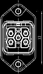
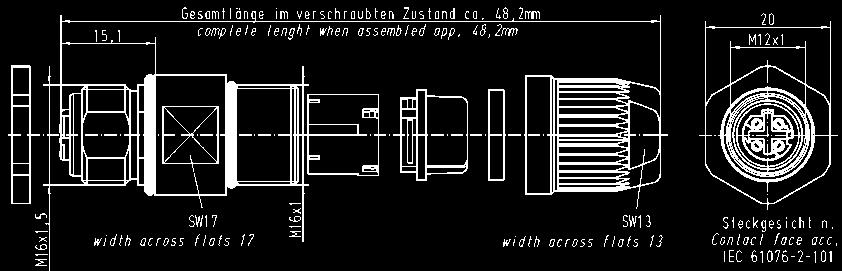
28 Han PushPull Power 4/0 Metal Features HARTING Push Pull Technology Compact design Finger protected Cable side; female insert - crimp termination - fast termination technology Han-Quick Lock Panel feed through - crimp termination - fast termination technology Han-Quick Lock - solder termination Technical characteristics Number of contacts 4 + PE Electrical data acc. to DIN EN Rated current 16 A Rated voltage - solder termination 230/400 V - crimp termination 690 V - Han-Quick Lock termination 690 V Degree of pollution 3 Locking system PushPull Degree of protection IP 65 / IP 67 Max. cable diameter 13 mm Wire gauge 2.5 mm² Flammability acc. to UL 94 V0 Material of housing Metal Acessories Part number Drawing Dimensions in mm Han PushPull dust protection cover for device side Han PushPull Power for cable side Han PushPull IP 65 for cable side Part number Crimp contacts Han P silver plated for 0.5 mm² for 0.75 mm² for 1.0 mm² for 1.5 mm² for 2.5 mm² Wire gauge Ø Stripping length for 0.5 mm² AWG mm 6 mm for 0.75 mm² AWG mm 6 mm for 1.0 mm² AWG mm 6 mm for 1.5 mm² AWG mm 6 mm for 2.5 mm² AWG mm 6 mm 28


29 Han PushPull Power 4/0 Metal Connector for device termination Han PushPull Power 4/0 Cable side including hood and female insert 16 A, 690 V with crimp termination please order crimp contacts separately Total length assembled approx mm Cable side including hood and female insert 16 A, 690 V with Han-Quick Lock termination Total length assembled approx mm Panel feed through including housing and male insert 16 A, 690 V with crimp termination please order crimp contacts separately Panel cut out Panel feed through including hood and male insert 16 A, 690 V with Han-Quick Lock termination Panel cut out Panel feed through including hood and male insert 16 A, 230/400 V on PCB with solder termination Panel cut out 29
30 Han PushPull Power 4/0 Plastic Features HARTING Push Pull Technology Compact design Finger protected Cable side; female insert - crimp termination - fast termination technology Han-Quick Lock Panel feed through - crimp termination - fast termination technology Han-Quick Lock - solder termination Technical characteristics Number of contacts 4 + PE Electrical data acc. to DIN EN Rated current 16 A Rated voltage - solder termination 230/400 V - crimp termination 690 V - Han-Quick Lock termination 690 V Degree of pollution 3 Locking system PushPull Degree of protection IP 65 / IP 67 Max. cable diameter 13 mm Wire gauge 2.5 mm² Flammability acc. to UL 94 V0 Material of housing Plastic Acessories Part number Drawing Dimensions in mm Han PushPull dust protection cover for device side Han PushPull Power for cable side Han PushPull IP 65 for cable side Part number Crimp contacts Han P silver plated for 0.5 mm² for 0.75 mm² for 1.0 mm² for 1.5 mm² for 2.5 mm² Wire gauge Ø Stripping length for 0.5 mm² AWG mm 6 mm for 0.75 mm² AWG mm 6 mm for 1.0 mm² AWG mm 6 mm for 1.5 mm² AWG mm 6 mm for 2.5 mm² AWG mm 6 mm 30


31 Han PushPull Power 4/0 Plastic Connector for device power supply Han PushPull Power 4/0 Cable side including hood and female insert 16 A 690 V with crimp termination please order crimp contacts separately Total length assembled approx mm Cable side including hood and female insert 16 A 690 V with Han-Quick Lock termination Total length assembled approx mm Panel feed through including housing and male insert 16 A 690 V with crimp termination please order crimp contacts separately Panel cut out Panel feed through including housing and male insert 16 A 690 V with Han-Quick Lock termination Panel cut out Panel feed through including housing and male insert 16 A, 230/400 V on PCB with solder termination Panel cut out 31
32 Han PushPull RJ45 Metal Features HARTING PushPull Technology Compact design High density Fast termination technique without tools PC board connection for device integration Panel feed through with different termination possibilities Technical characteristics Number of contacts 4, shielded Locking system PushPull Degree of protection IP 65 / IP 67 Max. cable diameter 9 mm AWG solid Transmission characteristic Cat 5e Flammability acc. to UL 94 V0 Material of housing Metal Acessories Part number Drawing Dimensions in mm Han PushPull dust protection cover for device side Han PushPull Power for cable side Han PushPull IP for cable side 32


33 Han PushPull RJ45 Metal Ethernet connector based on RJ45 Automation Initiative German Domestic Automobile Manufacturers Han PushPull RJ45 Metal PROFINET O-Plug RJ45 Total length assembled approx. 73 mm Cable side including hood and male insert HARTING RJ Industrial Han PushPull RJ45 Metal Panel feed through including housing and printed board with 2 x RJ45 jack horizontally mounted Panel cut out Panel feed through including housing and printed board with RJ45 jack and SEK board Panel cut out Panel feed through including housing and printed board with RJ45 jack and RJ45 jack vertically mounted in the IP20 range Panel cut out Panel feed through including housing and printed board with RJ45 jack and 47 jack vertically mounted in the IP20 range Panel cut out Recommendation for female insert and assembly manual on request. 33
34 Han PushPull RJ45 Plastic Features HARTING PushPull Technology Compact design High density Fast termination technique without tools PC board connection for device integration Panel feed through with different termination possibilities Technical characteristics Number of contacts 4, shielded Locking system PushPull Degree of protection IP 65 / IP 67 Max. cable diameter 9 mm AWG solid Transmission characteristic Cat 5e Flammability acc. to UL 94 V0 Material of housing Plastic Acessories Part number Drawing Dimensions in mm Han PushPull dust protection cover for device side Han PushPull Power for cable side Han PushPull IP for cable side 34


35 Han PushPull RJ45 Plastic Ethernet connector based on RJ45 Automation Initiative German Domestic Automobile Manufacturers Han PushPull RJ45 Plastic PROFINET O-Plug RJ45 Total length assembled approx. 67 mm Cable side including hood and male insert HARTING RJ Industrial Cable diameter mm Cable diameter mm Han PushPull RJ45 Plastic Panel feed through including housing and printed board with 2 x RJ45 jack horizontally mounted Panel cut out Panel feed through including housing and printed board with RJ45 jack and SEK board Panel cut out Panel feed through including housing and printed board with RJ45 jack and RJ45 jack vertically mounted in the IP20 range Panel cut out Panel feed through including housing and printed board with RJ45 jack and 47 jack vertically mounted in the IP20 range Panel cut out Recommendation for female insert and assembly manual on request. 35
 HCS = Hard Clad Silica (is registered trade mark of the SpecTran Corporation) 2) POF")


36 Han PushPull SCRJ Metal Optical connector based on SCRJ Advantages HARTING Push Pull Technology Compact design High density Transceiver for device integration 1) HCS = Hard Clad Silica (is registered trade mark of the SpecTran Corporation) 2) POF = Polymer-Optical Fibre Automation Initiative German Domestic Automobile Manufacturers General Description Locking system Push Pull Degree of protection IP 65 / IP 67 Mating face SCRJ acc. to IEC MM 50 µm / 125 µm MM 62.5 µm /125 µm SM 10 µm / 125 µm HCS 1) 200 µm / 230 µm POF 2) 1 mm Material of housing Metal Flammability according to UL 94 V0 Han PushPull SCRJ Metal PROFINET O-Plug SCRJ Total length assembled approx. 69 mm Cable side including hood and insert SCRJ order SC contacts separately Han PushPull SCRJ Panel feed through Panel cut out Available by August 2008 Contacts SC POF contact, 1 mm SC 125 GI contact SC 230 HCS contact Part number
 2) POF = Polymer-Optical Fibre Automation Initiative German Domestic Automobile")
 200 µm / 230 µm POF 2) 1 mm Material of housing Plastic Flammability according to UL 94 V0 Han PushPull SCRJ PROFINET O-Plug")

37 Han PushPull SCRJ Plastic Optical connector based on SCRJ Advantages HARTING Push Pull Technology Compact design High density Transceiver for device integration 1) HCS = Hard Clad Silica (is registered trade mark of the SpecTran Corporation) 2) POF = Polymer-Optical Fibre Automation Initiative German Domestic Automobile Manufacturers General Description Locking system Push Pull Degree of protection IP 65 / IP 67 Mating face SCRJ acc. to IEC MM 50 µm / 125 µm MM 62.5 µm /125 µm SM 10 µm / 125 µm HCS 1) 200 µm / 230 µm POF 2) 1 mm Material of housing Plastic Flammability according to UL 94 V0 Han PushPull SCRJ PROFINET O-Plug SCRJ Total length assembled approx. 69 mm Cable side including hood and insert SCRJ order SC contacts separately Han PushPull SCRJ Panel feed through Panel cut out Available by August 2008 Contacts SC POF contact, 1 mm SC 125 GI contact SC 230 HCS contact Part number
38 Circular Connectors with HARAX IDC Technical characteristics Approvals IEC HARAX M8-S HARAX M8-S (0.08 mm²) HARAX M12-S / / / 2405 Rated voltage 32 V 32 V 32 V Rated current 4 A 2 A 4 A (see current carrying capacity) wire gauge mm² mm² mm² AWG AWG AWG Diameter of individual strands Conductor insulation material PVC, PP, TPE PVC, PP, TPE PVC, PP, TPE Conductor diameter mm mm mm Cable diameter mm mm (transparent) mm (transparent) 3 seals mm (grey) mm (black) Limiting temperatures -25 C C -25 C C -25 C C Temperature during connection -5 C C -5 C C -5 C C Degree of protection IP 67 IP 67 IP 67 Termination cycles with the same cross section Recommended tightening torque / 0.4 Nm / Nm / Nm / 13 HARAX Han M12 HARAX IDC terminal Crimp terminal / / / Rated voltage 32 V 50 V 50 V Rated current (see current carrying capacity) 4 A 4 A 4 A wire gauge mm² mm² mm² AWG AWG AWG Diameter of individual strands Conductor insulation material PVC, cell PE PVC, PE PVC, PE Conductor diameter mm mm mm Cable diameter mm mm (black) mm mm (beige) Limiting temperatures -25 C C -25 C C -25 C C Temperature during connection -5 C C -5 C C -5 C C Degree of protection IP 67 IP 67 IP 67 Termination cycles with the same cross section Coding B A, D A, D Recommended tightening torque / 0.6 Nm / Nm / Nm / 17 38
39 Circular Connectors with HARAX IDC Features HARAX M8-S, 3 pins Less single parts 3 seals in one frame Corresponding seals are easy to assign HARAX M8-S for mm², 3 pins Well-known and proven HARAX IDC termination Short and robust design Wider range of suitable wire gauges for HARAX M8-S HARAX M12-S, 4 pins More comfortable handling Easy maintenance HARAX HARAX IDC termination Easy termination of the shielding No special tools necessary for assembly Current carrying capacity The current carrying capacity of the connectors is limited by the thermal load capability of the contact element material including the connections and the insulating parts. The de- tantly (non-intermittent) through each contact element of the connector evenly, without exceeding the allowed maximum temperature. Measuring and testing techniques acc. to DIN EN M8-S, 4 pins M12-S, 4 pins Panel feed through Han M12 with HARAX and crimp termination Short and robust design for harsh environments Available with HARAX and with crimp termination Field assembly possible Suitable for different types of shielded cables M12, Crimp 1 = wire gauge 0.34 mm² / 0.5 mm² 39


40 Circular Connectors M8/M12 with HARAX IDC HARAX M8-S, 0.08 mm² Male, straight version, 3 pins Available by July 2008 Set of 3 seals for HARAX M8-S for cable outer diameter mm mm mm HARAX M12-S Male, straight version, 4 pins Female, straight version, 4 pins HARAX M12-L, screened Male, 2 pins, B-coding HARAX M12-L, screened Female, 2 pins, B-coding


41 Panel Feed Throughs Han M12 HARAX panel feed through Male, A-coding Wire gauge mm² AWG: Cable outer diameter: mm Female, A-coding Wire gauge mm² AWG: Cable outer diameter: mm Han M12 panel feed through crimp Male, A-coding Cable outer diameter: mm Female, A-coding Cable outer diameter: mm HARAX panel feed through Female, D-coding Wire gauge mm² AWG: Cable outer diameter: mm HARAX panel feed through Female, D-coding Cable outer diameter: mm
, Fast Ethernet (100 Mbit/s) and Gigabit Ethernet (1000 Mbit/s).")

42 HARTING econ 2000 Introduction and features Ethernet Switch HARTING econ 2000 Ethernet Switches, unmanaged, in control cabinets General Description The Ethernet Switches of the product family HARTING econ 2000 are suitable for industrial applications and support Ethernet (10 Mbit/s), Fast Ethernet (100 Mbit/s) and Gigabit Ethernet (1000 Mbit/s). The product family enables the connection of up to 16 network devices (according to type) over shielded Twisted Pair cables. integrated LEDs on each port, the econ 2000 Ethernet Switch family supports fast and easy network diagnosis. The econ Ethernet Switch operates as an Unmanaged Switch in Store and Forward Switching Mode and supports Auto-crossing, Autonegotiation and Auto-polarity. Features l Auto-crossing l Auto-negotiation l Auto-polarity l Store and Forward Switching Mode For Ethernet Switch econ 2050-AA only: l complete designed for Gigabit Ethernet Due to their mechanical attachment, the econ 2000 Ethernet Switches can be mounted on or dismounted from standard 35 mm top-hat rails without tools. l Jumbo Frames up to 9728 Bytes l 4 K MAC addresses Advantages l Flat housing design l Industrial automation l Robust metal housing l Automotive industry l Adapted for mounting onto top-hat mounting rail 35 mm according to EN l RoHS compliant l Wind power l Power distribution systems 42
43 HARTING econ 2000 Technical characteristics econ 2160-A Ethernet interface RJ45 Number of ports Cable types according to IEEE x / 4x / 5x / 16x 10/100Base-T(X) Shielded Twisted Pair (STP) or Unshielded Twisted Pair (UTP), Category 5 10 Mbit/s or 100 Mbit/s (RJ45) Data rate Maximum cable length 100 m (Twisted Pair; with Category 5 cable acc. to DIN EN ) Termination RJ45 (Twisted Pair) Diagnostics (via LED) l Status Link Green l l Data transfer rate (Speed) 100 Mbit/s: Yellow 10 Mbit/s: OFF Topology Line, Star or mixed Power supply Input voltage Termination Diagnostics (via LED) 24 V DC (12 to 48 V DC) 5-pole pluggable screw contact (PRW1 + / PWR1 - / PWR2 + / PWR2 - / PE) Power supply - Green Design features Housing material Aluminium, anodised Dimensions (W x H x D) 120 x 105 x 25.5 mm (without connectors) Degree of protection acc. to DIN IP 30 Mounting 35 mm top-hat rail acc. to EN Weight approx. 0.4 kg Environmental conditions Operating temperature 10 C to +70 C Storage temperature 40 C to +85 C Relative humidity 10 % to 95 % (non-condensing) 43
44 HARTING econ 2000 Technical characteristics econ 2050-AA Ethernet interface RJ45 Number of ports Cable types according to IEEE x 10/100/1000Base-T(X) Shielded Twisted Pair (STP) or Unshielded Twisted Pair (UTP), Category 5 10, 100 or 1000 Mbit/s (RJ45) Data rate Maximum cable length 100 m (Twisted Pair; with Category 5 cable acc. to DIN EN ) Termination RJ45 (Twisted Pair) Diagnostics (via LED) l Status Link Green l l Data transfer rate (Speed) 1000 Mbit/s: Green 100 Mbit/s: Yellow 10 Mbit/s: OFF Topology Line, Star or mixed Power supply Input voltage Termination Diagnostics (via LED) 24 V DC (12 to 48 V DC) - redundant 5-pole pluggable screw contact (PRW1 + / PWR1 - / PWR2 + / PWR2 - / PE) Power supply (PWR1; PWR2) - Green Design features Housing material Aluminium, anodised Dimensions (W x H x D) 70 x 105 x 25.5 mm (without connectors) Degree of protection acc. to DIN IP 30 Mounting 35 mm top-hat rail acc. to EN Weight approx. 0.4 kg Environmental conditions Operating temperature 10 C to +70 C Storage temperature 40 C to +85 C Relative humidity 10 % to 95 % (non-condensing) 44
 Input voltage / Termination Permissible range (min/max) Input current 24 V DC / 5-pole pluggable screw contact (PRW1 + / PWR1 - / PWR2 + / PWR2 - / PE) 12 V to 48 V DC approx.")
45 HARTING econ 2000 Ethernet Switch HARTING econ 2160-A in control cabinets Unmanaged IP 30 PROFINET compatible X EtherNet/IP compatible Number of ports, Copper / Termination 16x 10/100Base-T(X) / RJ45 (Twisted Pair) Input voltage / Termination Permissible range (min/max) Input current 24 V DC / 5-pole pluggable screw contact (PRW1 + / PWR1 - / PWR2 + / PWR2 - / PE) 12 V to 48 V DC approx. 220 ma (at 24 V DC) Housing material Aluminium, anodised Dimensions (W x H x D) 120 x 105 x 25.5 mm (without connectors) Weight approx. 0.4 kg Operating temperature 10 C to +70 C Approvals cul (in preparation) HARTING econ 2160-A Ethernet Switch with 16 RJ45 ports
 / RJ45 (Twisted Pair) Input voltage / Termination Permissible range (min/max) Input current 24 V DC / 5-pole pluggable screw contact")
 Weight approx. 0.")
46 HARTING econ 2000 Ethernet Switch HARTING econ 2050-AA in control cabinets Unmanaged IP 30 PROFINET compatible X EtherNet/IP compatible Number of ports, Copper / Termination 5x 10/100/1000Base-T(X) / RJ45 (Twisted Pair) Input voltage / Termination Permissible range (min/max) Input current 24 V DC / 5-pole pluggable screw contact (PRW1 + / PWR1 - / PWR2 + / PWR2 - / PE) 12 V to 48 V DC approx. 250 ma (at 24 V DC) Housing material Aluminium, anodised Dimensions (W x H x D) 70 x 105 x 25.5 mm (without connectors) Weight approx. 0.4 kg Operating temperature 10 C to +70 C Approvals cul (in preparation) HARTING econ 2050-AA Gigabit Ethernet Switch with 5 RJ45 ports
47 HARTING econ 3000 Introduction and features Ethernet Mediaconverter HARTING econ 3011 Ethernet Mediaconverter, unmanaged, for installation in control cabinets General Description Features The Fast Ethernet Mediaconverter econ3011 of the product family HARTING econ 3000 is suitable for industrial applications and support both Ethernet (10 Mbit/s) and Fast Ethernet (100 Mbit/s). The Mediaconverter enables the conversion from shielded Twist- Singlemode). Switch and offers a variety of control functions. The Mediaconverter has two operating modes: In the switch mode, it operates as an unmanaged Ethernet Switch with Store and Forward Switching which supports asynchronous data communication, Auto-crossing and Auto-negotiation. In the converter mode, it works with a data rate of 100 Mbit/s (Full duplex). The latency is very low in this operation mode. l Converter Mode with a very low latency l Store and Forward switch mode l Link Fault Path Through (LFP) l Power over Ethernet (Power Source Equipment) l 9 kbyte Jumbo Frames in converter mode l 2 kbyte Frames in switch mode Advantages l Power over Ethernet (IEEE 802.3af) l Industrial automation l Automotive industry l Small and robust metal housing l Wind power l Adapted for mounting onto top-hat mounting rail 35 mm according to EN l Power distribution systems 47
48 HARTING econ 3000 Technical characteristics Media converter Ethernet interface RJ45 Number of ports Cable types according to IEEE x 10/100Base-T(X) Shielded Twisted Pair (STP) or Unshielded Twisted Pair (UTP), Category 5 10 Mbit/s or 100 Mbit/s (RJ45) Class II (latency 860 ns in converter mode) Data rate Repeater class Maximum cable length 100 m (Twisted Pair; with Category 5 cable acc. to DIN EN ) Termination RJ45 (Twisted Pair) Diagnostics (via LED) l Status Link Green l l Data transfer rate (Speed) 100 Mbit/s: Yellow / 10 Mbit/s: OFF l Duplex Full duplex: Yellow / Half duplex: OFF l PoE (Power Source Equipment) (PSE) Green Topology Line Power supply Input voltage Input voltage, mode PoE Termination Diagnostics (via LED) 24 V DC (12 to 30 V DC) 48 V DC (46 to 57 V DC) 5-pole pluggable screw contact (PRW1 + / PWR1 - / PWR2 + / PWR2 - / PE) Power supply - Green C via DIP switches: Mode, Auto-negotiation, Data rate, Duplex TP, Duplex FX, Link Fault Path Through, PoE (PSE) Design features Housing material Metal (powder coated) Dimensions (W x H x D) 23 x 130 x 100 mm (without connectors) Degree of protection acc. to DIN IP 30 Mounting 35 mm top-hat rail acc. to EN Weight approx. 0.6 kg Environmental conditions Operating temperature 40 C to +70 C Storage temperature 40 C to +85 C Relative humidity 10 % to 95 % (non-condensing) 48
49 HARTING econ 3000 Technical characteristics Media converter - F.O. termination Ethernet interface F.O. Number of ports Data rate Link monitoring Maximum cable length Termination Diagnostics (via LED) Wavelength Transceive power T(X) max. (dynamic) Transmission power T(X) min. Receive power RX typical (dynamic) Receive power RX max. (dynamic) Signal detection (dynamic) Topology 1x 100Base-FX 100 Mbit/s Link Fault Path Through (LFP) 2000 m (Multimode) SC-D female l Status Link Green l l Duplex Full duplex: Yellow / Half duplex: OFF 1300 nm l -14 dbm (50 / 125 µm) l -14 dbm (62.5 / 125 µm) l dbm (50 / 125 µm) l -20 dbm (62.5 / 125 µm) l dbm (window) l dbm (centre) -14 dbm -33 dbm Line 49
 Unmanaged IP 30 PROF")
 / RJ45 (Twisted Pair) 1x 100Base-FX / SC-D female Input voltage / Termination Permissible range (min/max) Input voltage mode PoE Permissible range (min/max) Input")
50 HARTING econ 3000 Ethernet Media converter HARTING econ 3011-AD 2-port Ethernet Media converter for vertical installation in control cabinets including 1 F.O. port (SC, MM) Unmanaged IP 30 PROFINET compatible X EtherNet/IP compatible Number of ports, Copper / Termination Number of ports, F.O. / Termination 1x 10/100Base-T(X) / RJ45 (Twisted Pair) 1x 100Base-FX / SC-D female Input voltage / Termination Permissible range (min/max) Input voltage mode PoE Permissible range (min/max) Input current 24 V DC / 5-pole pluggable screw contact, redundancy (PRW1 + / PWR1 - / PWR2 + / PWR2 - / PE) 12 V to 48 V DC 48 V DC when using as PSE 46 V to 57 V DC approx. 100 ma (at 24 V DC) approx. 100 ma to 400 ma (at 48 V DC with PoE) Housing material Metal (powder coated) Dimensions (W x H x D) 23 x 130 x 100 mm (without connectors) Weight approx. 0.6 kg Operating temperature 40 C to +70 C Approvals cul (in preparation) HARTING econ 3011-AD Ethernet Media converter with 1 RJ45 port 1 F.O. port
 Unmanaged IP 30 PROF")
 / RJ45 (Twisted Pair) 1x 100 Mbit/s SFP module slot Input voltage / Termination Permissible range (min/max) Input voltage mode PoE Permissible range (min/max) Input")
51 HARTING econ 3000 Ethernet Media converter HARTING econ 3011-ASFP 2-port Ethernet Media converter for vertical installation in control cabinets including 1 F.O. port (SFP) Unmanaged IP 30 PROFINET compatible X EtherNet/IP compatible Number of ports, Copper / Termination Number of ports, F.O. / Termination 1x 10/100Base-T(X) / RJ45 (Twisted Pair) 1x 100 Mbit/s SFP module slot Input voltage / Termination Permissible range (min/max) Input voltage mode PoE Permissible range (min/max) Input current 24 V DC / 5-pole pluggable screw contact, redundant (PRW1 + / PWR1 - / PWR2 + / PWR2 - / PE) 12 V to 48 V DC 48 V DC when using as PSE 46 V to 57 V DC approx. 100 ma (at 24 V DC) approx. 100 ma to 400 ma (at 48 V DC with PoE) Housing material Metal (powder coated) Dimensions (W x H x D) 23 x 130 x 100 mm (without connectors) Weight approx. 0.6 kg Operating temperature 40 C to +70 C Approvals cul (in preparation) HARTING econ 3011-ASFP Ethernet Media converter with 1 RJ45 port 1 port SFP module slot Optional accessories: SFP modules (see page 78) 51

52 HARTING scon Introduction and features Introduction For the user, HARTING s innovative solution opens up new, more convenient and extensive options solutions available to date offered only very limited or simple options for making alterations to different settings on an Ethernet switch. makes it possible for the user to implement many possible. Ease of handling and operation has been designed in for real-life applications. The goal of ration. All Ethernet switches in HARTING s scon connection cable. from Ethernet switches available to date. The possi- to the user when the Ethernet switch is connected to a PC, laptop or hand-held PC via its front-panel USB port. Once the scon Ethernet switch has been connected to a PC, it displays in the same manner as a commercially available USB stick (refer to Figure 1: The start-up menu). The user needs only to copy the scon software in advance onto the respective PC. No administrator rights are required. pear to be uncomplicated. However, accidentally more quickly than one would think possible, and in so doing make considerable changes to the previously-set procedures. The scon product family pre- - without a USB connection and the software. The previous ring solutions on the market were proprietary or based on IEEE standard software solutions of the Rapid Spanning Tree Proto- tions were often unacceptable because of their high costs. The ring redundancy of the scon product family, based on unmanaged switches, is better suited to user requirements. With previous solutions, functions such as port mirroring, port redundancy, port prioritization or ring redundancy were reserved for managed Ethernet switches. HARTING s scon product family has the quirements of many applications. If the conditions at a facility change on-site, the Ethernet switch can be quickly and easily adapted to new circumstances guration can be transferred to the Ethernet switch switch function functions as a plug-and-play switch with its standard parameters. While scon is a solution for unmanaged Ethernet switches, it does comes very close to the functionality of a managed Ethernet switch. 52 Figure 1 The start-up menu
53 HARTING scon 3000 Introduction and features Ethernet Switch HARTING scon 3000 Ethernet Switch family, unmanaged, for mounting onto top-hat mounting rail in control cabinets including scon functions General Description The Fast Ethernet Switches of the product family port for special or more performance-oriented industrial usages. There are almost no limits to the different possibilities. Features l Ethernet Switch acc. to IEEE l Store and Forward Switching Mode, non-blocking, unmanaged Activation of parallel and / or ring redundancy or port prioritisation will clearly increase the availability and reliability of data communications through the scon l Auto-crossing, Auto-negotiation, Auto-polarity l Diagnostic LEDs (Link status, Act, Power, Data transmission rate, Error) l Following settings are available via USB port: l Alarm signalling contact l Auto-negotiation l 10/100/1000 Mbit/s l Full/Half Duplex l Ring and/or parallel redundancy l Port enable / disable l Port priority l Port mirroring Advantages l l Industrial automation l Metal housing l Railway applications l EMC, temperature range and mechanical stability meet the toughest demands l Ring and/or parallel redundancy l Power distribution systems l Automotive industry l Mechanical engineering 53
54 HARTING scon 3000 Technical characteristics Ethernet interface RJ45 Number of ports Cable types according to IEEE x / 8x / 10x 10/100Base-T(X), 2x 10/100/1000Base-T(X) Shielded Twisted Pair (STP) or Unshielded Twisted Pair (UTP), Category 5 10 Mbit/s, 100 Mbit/s or 1000 Mbit/s (RJ45) Data rate Maximum cable length 100 m (Twisted Pair; with Category 5 cable acc. to DIN EN ) Termination RJ45 (Twisted Pair) Diagnostics (via LED) l Status Link Green l l Data transfer rate (Speed) 1000 Mbit/s: Green 100 Mbit/s: Yellow 10 Mbit/s: OFF Topology Line, Ring, Star or mixed Power supply Input voltage Termination Diagnostics (via LED) 24 V DC 5-pole screw terminal, pluggable for redundant power supply Power supply Alarm signalling contact Change-over contact, potential-free, 24 V DC / 0.5 A 3-pole pluggable screw contact Design features Housing material Metal (powder coated) Dimensions (W x H x D) 60 x 132 x 104 mm (incl. cap, without connectors) Degree of protection acc. to DIN IP 30 scon xxxx-ae IP 20 Mounting l 35 mm top-hat rail acc. to EN l Panel mounting, vertical assembly Weight approx. 0.6 kg Environmental conditions Operating temperature 0 C to +70 C Storage temperature 40 C to +85 C Relative humidity 10 % to 95 % (non-condensing) 54
55 HARTING scon 3000 Technical characteristics - F.O. termination Ethernet interface F.O. Number of ports Cable types according to IEEE Data rate Maximum cable length Termination Diagnostics (via LED) Wavelength Transceive power T(X) max. (dynamic) Transmission power T(X) min. Receive power RX typical (dynamic) Receive power RX max. (dynamic) Signal detection (dynamic) Topology 1x / 2x / 3x 100Base-FX l l 100 Mbit/s l 2000 m (Multimode) l 15 km (Singlemode) SC-D female / ST female l Status Link Green l 1300 nm l -14 dbm (50 / 125 µm) l -14 dbm (62.5 / 125 µm) l dbm (50 / 125 µm) l -20 dbm (62.5 / 125 µm) l dbm (window) l dbm (centre) -14 dbm -33 dbm Line, Ring, Star or mixed 55
 and scon functions Unmanaged IP 20 PROF")
 / RJ45 (Twisted Pair) 1x 100Base-FX / ST female Input voltage / Termination Permissible range (min/max) Input current Alarm")
 Change-over contact, potential-free, 24 V DC / 0.")
56 HARTING scon 3000 Ethernet Switch HARTING scon 3061-AE 7-port Ethernet Switch for mounting onto top-hat mounting rail in control cabinets including 1 F.O. port (ST, MM) and scon functions Unmanaged IP 20 PROFINET compatible X EtherNet/IP compatible Number of ports, Copper / Termination Number of ports, F.O. / Termination 6x 10/100Base-T(X) / RJ45 (Twisted Pair) 1x 100Base-FX / ST female Input voltage / Termination Permissible range (min/max) Input current Alarm signalling contact 24 V DC / 5-pole screw terminal, pluggable redundant power supply 9.6 V to 36 V DC approx. 240 ma (at 24 V DC) Change-over contact, potential-free, 24 V DC / 0.5 A 3-pole pluggable screw contact Housing material Metal (powder coated) Dimensions (W x H x D) 60 x 132 x 104 mm (incl. cap, without connectors) Weight approx. 0.6 kg Operating temperature 0 C to +70 C Approvals UL 508 MTBF h HARTING scon 3061-AE Ethernet Switch 6 RJ45 ports 1 ST port including Set for assembly on standard rail
 and scon functions Unmanaged IP 20 PROF")
 / RJ45 (Twisted Pair) 3x 100Base-FX / ST female Input voltage / Termination Permissible range (min/max) Input current Alarm signalling contact 24 V DC / 5-pole screw")
57 HARTING scon 3000 Ethernet Switch HARTING scon 3063-AE 9-port Ethernet Switch for mounting onto top-hat mounting rail in control cabinets including 3 F.O. ports (ST, MM) and scon functions Unmanaged IP 20 PROFINET compatible X EtherNet/IP compatible Number of ports, Copper / Termination Number of ports, F.O. / Termination 6x 10/100Base-T(X) / RJ45 (Twisted Pair) 3x 100Base-FX / ST female Input voltage / Termination Permissible range (min/max) Input current Alarm signalling contact 24 V DC / 5-pole screw terminal, pluggable redundant power supply 9.6 V to 36 V DC approx. 290 ma (at 24 V DC) Change-over contact, potential-free, 24 V DC / 0.5 A 3-pole pluggable screw contact Housing material Metal (powder coated) Dimensions (W x H x D) 60 x 132 x 104 mm (incl. cap, without connectors) Weight approx. 0.6 kg Operating temperature 0 C to +70 C Approvals UL 508 MTBF h HARTING scon 3063-AE Ethernet Switch 6 RJ45 ports 3 ST ports including Set for assembly on standard rail
 and scon functions Unmanaged IP 20 PROF")
 / RJ45 (Twisted Pair) 2x 100Base-FX / ST female Input voltage / Termination Permissible range (min/max) Input current Alarm signalling contact 24 V DC / 5-pole screw")
58 HARTING scon 3000 Ethernet Switch HARTING scon 3082-AE 10-port Ethernet Switch for mounting onto top-hat mounting rail in control cabinets including 2 F.O. ports (ST, MM) and scon functions Unmanaged IP 20 PROFINET compatible X EtherNet/IP compatible Number of ports, Copper / Termination Number of ports, F.O. / Termination 8x 10/100Base-T(X) / RJ45 (Twisted Pair) 2x 100Base-FX / ST female Input voltage / Termination Permissible range (min/max) Input current Alarm signalling contact 24 V DC / 5-pole screw terminal, pluggable redundant power supply 9.6 V to 36 V DC approx. 260 ma (at 24 V DC) Change-over contact, potential-free, 24 V DC / 0.5 A 3-pole pluggable screw contact Housing material Metal (powder coated) Dimensions (W x H x D) 60 x 132 x 104 mm (incl. cap, without connectors) Weight approx. 0.6 kg Operating temperature 0 C to +70 C Approvals UL 508 MTBF h HARTING scon 3082-AE Ethernet Switch 8 RJ45 ports 2 ST ports including Set for assembly on standard rail
 and scon functions Unmanaged IP 30 PROF")
59 HARTING scon 3000 Ethernet Switch HARTING scon 3061-AF 7-port Ethernet Switch for mounting onto top-hat mounting rail in control cabinets including 1 F.O. port (SC, SM) and scon functions Unmanaged IP 30 PROFINET compatible X EtherNet/IP compatible Number of ports, Copper / Termination Number of ports, F.O. / Termination 6x 10/100Base-T(X) / RJ45 (Twisted Pair) 1x 100Base-FX / SC-D female (Singlemode) Input voltage / Termination Permissible range (min/max) Input current Alarm signalling contact 24 V DC / 5-pole screw terminal, pluggable redundant power supply 9.6 V to 36 V DC approx. 240 ma (at 24 V DC) Change-over contact, potential-free, 24 V DC / 0.5 A 3-pole pluggable screw contact Housing material Metal (powder coated) Dimensions (W x H x D) 60 x 132 x 104 mm (incl. cap, without connectors) Weight approx. 0.6 kg Operating temperature 0 C to +70 C Approvals cul (in preparation) HARTING scon 3061-AF Ethernet Switch 6 RJ45 ports 1 SC port including Set for assembly on standard rail
 and scon functions Unmanaged IP 30 PROF")
 / RJ45 (Twisted Pair) 2x 100Base-FX / SC-D female (Singlemode) Input voltage / Termination Permissible range (min/max) Input current Alarm signalling contact 24 V DC")
60 HARTING scon 3000 Ethernet Switch HARTING scon 3082-AF 10-port Ethernet Switch for mounting onto top-hat mounting rail in control cabinets including 2 F.O. ports (SC, SM) and scon functions Unmanaged IP 30 PROFINET compatible X EtherNet/IP compatible Number of ports, Copper / Termination Number of ports, F.O. / Termination 8x 10/100Base-T(X) / RJ45 (Twisted Pair) 2x 100Base-FX / SC-D female (Singlemode) Input voltage / Termination Permissible range (min/max) Input current Alarm signalling contact 24 V DC / 5-pole screw terminal, pluggable redundant power supply 9.6 V to 36 V DC approx. 260 ma (at 24 V DC) Change-over contact, potential-free, 24 V DC / 0.5 A 3-pole pluggable screw contact Housing material Metal (powder coated) Dimensions (W x H x D) 60 x 132 x 104 mm (incl. cap, without connectors) Weight approx. 0.6 kg Operating temperature 0 C to +70 C Approvals cul (in preparation) HARTING scon 3082-AF Ethernet Switch 8 RJ45 ports 2 SC ports including Set for assembly on standard rail
61 HARTING mcon 3000 Introduction and features Ethernet Switch HARTING mcon 3000 Ethernet Switches, managed, for mounting onto top-hat mounting rail in control cabinets General Description The fully Managed Ethernet Switches of the product family HARTING mcon 3000 enable the connection of up to 10 network devices (according to type) over (Multi- and Singlemode). The mcon 3000 Ethernet Switch family, with its integrated LEDs on each port, supports fast and easy network diagnosis. The mcon 3000 Ethernet Switches are designed for an effective, industrial and individual use. They support both SNMP and an easy Web interface for management functions. Features l Ethernet Switch acc. to IEEE l Store and Forward Switching Mode l up to 10 ports, managed, non-blocking l Auto-crossing, Auto-negotiation, Auto-polarity Advantages l Metal housing l Industrial automation l EMC, temperature range and mechanical stability meet the highest demands l Integrated management functions l Automotive industry l Wind power l Power distribution systems 61
62 HARTING mcon 3000 Technical characteristics Ethernet interface RJ45 Number of ports Cable types according to IEEE x / 8x / 10x 10/100Base-T(X), 2x 10/100/1000Base-T(X) Shielded Twisted Pair (STP) or Unshielded Twisted Pair (UTP), Category 5 10 Mbit/s, 100 Mbit/s or 1000 Mbit/s (RJ45) Data rate Maximum cable length 100 m (Twisted Pair; with Category 5 cable acc. to DIN EN ) Termination RJ45 (Twisted Pair) Diagnostics (via LED) l Status Link Green l l Data transfer rate (Speed) 1000 Mbit/s: Green 100 Mbit/s: Yellow 10 Mbit/s: OFF Topology Ring, Line, Star or mixed Power supply Input voltage Termination Diagnostics (via LED) 24 V DC 5-pole screw terminal, pluggable for redundant power supply Power supply Alarm signalling contact Change-over contact, potential-free, 24 V DC / 0.5 A 3-pole pluggable screw contact Design features Housing material Metal (powder coated) Dimensions (W x H x D) 60 x 132 x 104 mm (incl. cap, without connectors) Degree of protection acc. to DIN IP 30 mcon xxxx-ae IP 20 Mounting l 35 mm top-hat rail acc. to EN l Panel mounting, vertical assembly Weight approx. 0.6 kg Environmental conditions Operating temperature 0 C to +70 C Storage temperature 40 C to +85 C Relative humidity 10 % to 95 % (non-condensing) 62
63 HARTING mcon 3000 Technical characteristics - F.O. termination Ethernet interface F.O. Number of ports Data rate Maximum cable length Termination Diagnostics (via LED) Wavelength Transceive power T(X) max. (dynamic) Transmission power T(X) min. Receive power RX typical (dynamic) Receive power RX max. (dynamic) Signal detection (dynamic) Topology 1x / 2x / 3x 100Base-FX 100 Mbit/s 2000 m (Multimode) SC-D female / ST female l Status Link Green l 1300 nm l -14 dbm (50 / 125 µm) l -14 dbm (62.5 / 125 µm) l dbm (50 / 125 µm) l -20 dbm (62.5 / 125 µm) l dbm (window) l dbm (centre) -14 dbm -33 dbm Ring, Line, Star or mixed 63
64 HARTING mcon 3000 Management functions Basic functions l Store and Forward Switching Mode (IEEE 802.3) l l IGMP Snooping and Querier (IEEE 802.1) l VLAN (IEEE 802.1Q) l Spanning Tree Protocol (STP) (IEEE 802.1D) l Rapid Spanning Tree (RSTP) (IEEE 802.1W) l QoS (IEEE 802.1P) l DHCP Client SNMP Web-based access (password protection) Additional services Diagnostics l SNMP V1 and SNMP V3 l Enterprise (HARTING MIB) l MIB II l RMON (statistics, history, alarm, events) l Dot1Bridge l SnmpDot3mauMIB l PtopoMIB l EntityMIB l RstpMIB l System l ifmib l ICMP l IP l TCP l at l UDP l SNMP l transmission l Status overview l Port settings l l Password settings l Alarm settings l Diagnostics l Parameter Import / Export l Firmware Import / Export l SMTP l l System time via SNTP l Service Mode via port 1 l LEDs for Power, Link, Status, Data transmission and Fault l Port diagnostic l Port Mirroring l History l Alarms via and SNMP Traps l Signalling contact for low voltage detection and Link break 64 Additional information about Management functions and Firmware updates can be found on our Web server.
 Managed IP 20 PROF")
65 HARTING mcon 3000 Ethernet Switch HARTING mcon 3061-AE 7-port Ethernet Switch for mounting onto top-hat mounting rail in control cabinets including 1 F.O. port (ST, MM) Managed IP 20 PROFINET compatible X EtherNet/IP compatible X Number of ports, Copper / Termination Number of ports, F.O. / Termination 6x 10/100Base-T(X) / RJ45 (Twisted Pair) 1x 100Base-FX / ST female Input voltage / Termination Permissible range (min/max) Input current Alarm signalling contact 24 V DC / 5-pole screw terminal, pluggable redundant power supply 9.6 V to 36 V DC approx. 270 ma (at 24 V DC) Change-over contact, potential-free, 24 V DC / 0.5 A 3-pole pluggable screw contact Housing material Metal (powder coated) Dimensions (W x H x D) 60 x 132 x 104 mm (incl. cap, without connectors) Weight approx. 0.6 kg Operating temperature 0 C to +70 C Approvals UL 508 MTBF h Management fully Managed via Web interface and SNMP Functions see page 64 HARTING mcon 3061-AE Ethernet Switch, managed 6 RJ45 ports 1 ST port including Set for assembly on standard rail
 Managed IP 20 PROF")
 / RJ45 (Twisted Pair) 3x 100Base-FX / ST female Input voltage / Termination Permissible range (min/max) Input current Alarm signalling contact 24 V DC / 5-pole screw")
66 HARTING mcon 3000 Ethernet Switch HARTING mcon 3063-AE 9-port Ethernet Switch for mounting onto top-hat mounting rail in control cabinets including 3 F.O. ports (ST, MM) Managed IP 20 PROFINET compatible X EtherNet/IP compatible X Number of ports, Copper / Termination Number of ports, F.O. / Termination 6x 10/100Base-T(X) / RJ45 (Twisted Pair) 3x 100Base-FX / ST female Input voltage / Termination Permissible range (min/max) Input current Alarm signalling contact 24 V DC / 5-pole screw terminal, pluggable redundant power supply 9.6 V to 36 V DC approx. 320 ma (at 24 V DC) Change-over contact, potential-free, 24 V DC / 0.5 A 3-pole pluggable screw contact Housing material Metal (powder coated) Dimensions (W x H x D) 60 x 132 x 104 mm (incl. cap, without connectors) Weight approx. 0.6 kg Operating temperature 0 C to +70 C Approvals UL 508 MTBF h Management fully Managed via Web interface and SNMP Functions see page 64 HARTING mcon 3063-AE Ethernet Switch, managed 6 RJ45 ports 3 ST ports including Set for assembly on standard rail
 Managed IP 20 PROF")
 / RJ45 (Twisted Pair) 2x 100Base-FX / ST female Input voltage / Termination Permissible range (min/max) Input current Alarm signalling contact 24 V DC / 5-pole screw")
67 HARTING mcon 3000 Ethernet Switch HARTING mcon 3082-AE 10-port Ethernet Switch for mounting onto top-hat mounting rail in control cabinets including 2 F.O. ports (ST, MM) Managed IP 20 PROFINET compatible X EtherNet/IP compatible X Number of ports, Copper / Termination Number of ports, F.O. / Termination 8x 10/100Base-T(X) / RJ45 (Twisted Pair) 2x 100Base-FX / ST female Input voltage / Termination Permissible range (min/max) Input current Alarm signalling contact 24 V DC / 5-pole screw terminal, pluggable redundant power supply 9.6 V to 36 V DC approx. 290 ma (at 24 V DC) Change-over contact, potential-free, 24 V DC / 0.5 A 3-pole pluggable screw contact Housing material Metal (powder coated) Dimensions (W x H x D) 60 x 132 x 104 mm (incl. cap, without connectors) Weight approx. 0.6 kg Operating temperature 0 C to +70 C Approvals UL 508 MTBF h Management fully Managed via Web interface and SNMP Functions see page 64 HARTING mcon 3082-AE Ethernet Switch, managed 8 RJ45 ports 2 ST ports including Set for assembly on standard rail
, Fast Ethernet (100 Mbit/s) and Gigabit Ethernet (1000 Mbit/s), HARTING's manageable Fast Ethernet Switch product family mcon 1000 is suitable for use in industrial")
68 HARTING mcon 1000 Introduction and features Ethernet Switch HARTING mcon 1000 Ethernet Switches, managed, for mounting onto top-hat mounting rail in control cabinets General Description Features Supporting Ethernet (10 Mbit/s), Fast Ethernet (100 Mbit/s) and Gigabit Ethernet (1000 Mbit/s), HARTING's manageable Fast Ethernet Switch product family mcon 1000 is suitable for use in industrial environments. The product family mcon 1000 is particularly well suited for communications networks in power distribution stations, wind turbine facilities, or similar applications. Selected Ethernet Switchs of this product family conform to the demands of the IEC Up to 10 Ethernet stations can be connected to the Ether- cal cables. The protection class, temperature range and mechanical stability ensure a high level of operational security and suitability for the most demanding industrial requirements. l Protocol-transparent transmission l Store-and-forward switching mode, self-learning l mode (HDX) l Flow Control according to IEEE 802.3x in full-duplex mode (FDX) l High performance non-blocking switching fabric l Ring, star and line topologies, can be implemented in any way Advantages l Robust metal housing l Railway applications l EMC, temperature range and mechanical stability meet the highest demands l Management functions are integrated l Industrial automation l Automotive industry l Wind power 68
69 HARTING mcon 1000 Technical characteristics Ethernet interface RJ45 Number of ports Cable types according to IEEE x / 6x / 7x 10/100/1000Base-T(X) 1x 10/100/1000Base-T(X) (mcon 1082-AD and mcon 1083-ASFP only) Shielded Twisted Pair (STP) or Unshielded Twisted Pair (UTP), Category 5 10 Mbit/s, 100 Mbit/s or 1000 Mbit/s (RJ45) Data rate Maximum cable length 100 m (Twisted Pair; with Category 5 cable acc. to DIN EN ) Termination RJ45 (Twisted Pair) Diagnostics (via LED) l Status Link active: Green l Transmission mode (FDX) Full duplex: Yellow l Management (State) active: Green Topology Ring, Line, Star or mixed Power supply Input voltage Termination 24 V DC (18 to 36 V DC) 48 V DC (44 to 57 V DC) 4-pole screw terminal, pluggable for redundant power supply Diagnostics (via LED) l Power supply S1 present Green l Power supply S2 present Green l Power supply S4/S5 present Green l Operating state (Run) Green Alarm signalling contact 2 change-over contacts, potential-free, 30 V DC / 1 A 4-pole pluggable screw contact Diagnostics (via LED) l Alarm signalling contact M1 active: Red l Alarm signalling contact M2 active: Red Design features Housing material Metal (coated) Dimensions (W x H x D) mcon 1052 / 1061 / x 105 x 106 mm (without connectors) mcon 1082 / x 105 x 106 mm (without connectors) Degree of protection acc. to DIN IP 30 Mounting l 35 mm top-hat rail acc. to EN l Panel mounting, vertical assembly Weight approx. 0.8 kg Environmental conditions Operating temperature -10 C to +60 C -40 C to +70 C on request Storage temperature -20 C to +85 C Relative humidity 20 % to 90 % (non-condensing) 69
70 HARTING mcon 1000 Technical characteristics F.O. terminations Ethernet interface F.O. Number of ports Cable types according to IEEE Data rate Maximum cable length Termination Diagnostics (via LED) Wavelength Transceive power T(X) max. Transmission power T(X) min. Receive power RX max Receive power RX min Topology 1x/2x 100Base-FX (AD variants only) 2x 1000Base-FX (mcon 1082-AD only) l 100 Mbit/s or 1000 Mbit/s l 2000 m (Multimode) SC-D female l Status Link Green l 1300 nm l -14 dbm (50 / 125 µm) l -14 dbm (62.5 / 125 µm) l dbm (50 / 125 µm) l -20 dbm (62.5 / 125 µm) -8 dbm -31 dbm Ring, Line, Star or mixed 70
71 HARTING mcon 1000 Management functions Basic functions l Store and Forward Switching Mode (IEEE 802.3) l l IGMP Snooping and Querier (IEEE 802.1) l VLAN (IEEE 802.1Q) l Spanning Tree Protocol (STP) (IEEE 802.1D) l Rapid Spanning Tree (RSTP) (IEEE 802.1W) l QoS (IEEE 802.1P) l DHCP Client, BootP l Port based Network Access control (IEEE 802.1x) l RADIUS SNMP l SNMP V1 and SNMP V2 l Enterprise (HARTING MIB) l MIB II l RMON (statistics, history, alarm, events) l Dot1Bridge l DHCP Options l ICMP l IP l TCP l UDP l SNMP Web-based access (password protection) l Status overview l Port settings l l Password settings l Alarm settings l Diagnostics Additional services l SYSLOG l l System time via SNTP Diagnostics l LEDs for Power, Link, Status, Data transmission and Fault l Port diagnostic l Port Mirroring l History l Alarms via SYSLOG and SNMP Traps Additional information about Management functions and Firmware updates can be found on our Web server. 71
 Managed IP 30 PROF")
72 HARTING mcon 1000 Ethernet Switch HARTING mcon 1052-AD 7-port Ethernet Switch for mounting onto top-hat mounting rail in control cabinets including 2 F.O. ports (SC, MM) Managed IP 30 PROFINET compatible EtherNet/IP compatible X Number of ports, Copper / Termination Number of ports, F.O. / Termination 5x 10/100Base-T(X) / RJ45 (Twisted Pair) 2x 100Base-FX / SC-Duplex female Input voltage / Termination Permissible range (min/max) Input current Alarm signalling contact 24 V DC / 4-pole screw terminal, pluggable redundant power supply 48 V DC / 2-pole screw terminal, pluggable 18 V to 36 V DC (at 24 V DC) / 44 V to 57 V DC (at 48 V DC) approx. 290 ma (at 24 V DC) 2 change-over contacts, potential-free, 30 V DC / 1 A 4-pole pluggable screw contact Housing material Metal Dimensions (W x H x D) 75 x 105 x 106 mm (without connectors) Weight approx. 0.8 kg Operating temperature -10 C to +60 C MTBF h (20 C according to SN :1995) Management fully Managed via Web interface, SNMP, Telnet and V.24 (RS 232) Functions see page 71 HARTING mcon 1052-AD Ethernet Switch, managed, with 5 ports RJ45 and 2 ports F.O. (SC-Duplex) including Set for assembly on standard rail
 / RJ45 (Twisted Pair) 2x plug-in slot for SFP modules (100")

73 HARTING mcon 1000 Ethernet Switch HARTING mcon 1052-ASFP 7-port Ethernet Switch for mounting onto top-hat mounting rail in control cabinets including 2 ports for SFP modules IEC compliant Managed IP 30 PROFINET compatible EtherNet/IP compatible X Number of ports, Copper / Termination Number of other ports 5x 10/100Base-T(X) / RJ45 (Twisted Pair) 2x plug-in slot for SFP modules (100 MB, see Accessories) Input voltage / Termination Permissible range (min/max) Input current Alarm signalling contact 24 / 48 V DC / 4-pole screw terminal, pluggable redundant power supply 21 V to 57 V DC approx. 290 ma (at 24 V DC) 2 change-over contacts, potential-free, 30 V DC / 1 A 4-pole pluggable screw contact Housing material Metal Dimensions (W x H x D) 75 x 105 x 106 mm (without connectors) Weight approx. 0.8 kg Operating temperature -10 C to +60 C -40 C to +70 C on request Management fully Managed via Web interface, SNMP, Telnet and V.24 (RS 232) Functions see page 71 HARTING mcon 1052-ASFP Ethernet Switch, managed, with 5 ports RJ45 and 2 ports for SFP modules including Set for assembly on standard rail
 Managed IP 30 PROF")
 / RJ45 (Twisted Pair) 1x 100Base-FX / SC-Duplex female Input voltage / Termination Permissible range (min/max) Input current Alarm signalling contact 24 V DC / 4-pole")
74 HARTING mcon 1000 Ethernet Switch HARTING mcon 1061-AD 7-port Ethernet Switch for mounting onto top-hat mounting rail in control cabinets including 1 F.O. port (SC, MM) Managed IP 30 PROFINET compatible EtherNet/IP compatible X Number of ports, Copper / Termination Number of ports, F.O. / Termination 6x 10/100Base-T(X) / RJ45 (Twisted Pair) 1x 100Base-FX / SC-Duplex female Input voltage / Termination Permissible range (min/max) Input current Alarm signalling contact 24 V DC / 4-pole screw terminal, pluggable redundant power supply 48 V DC / 2-pole screw terminal, pluggable 18 V to 36 V DC (at 24 V DC) / 44 V to 57 V DC (at 48 V DC) approx. 290 ma (at 24 V DC) 2 change-over contacts, potential-free, 30 V DC / 1 A 4-pole pluggable screw contact Housing material Metal Dimensions (W x H x D) 75 x 105 x 106 mm (without connectors) Weight approx. 0.8 kg Operating temperature -10 C to +60 C MTBF h (20 C according to SN :1995) Management fully Managed via Web interface, SNMP, Telnet and V.24 (RS 232) Functions see page 71 HARTING mcon 1061-AD Ethernet Switch, managed, with 6 ports RJ45 and 1 port F.O. (SC-Duplex) including Set for assembly on standard rail
 / RJ45 (Twisted Pair) Input voltage / Termination Permissible range (min/max) Input current Alarm signalling contact 24 V DC / 4-pole screw")
 2 change-over contacts, potential-free, 30 V DC / 1 A 4-pole pluggable screw contact Housing material Metal Dimensions (W x H x D) 75 x 105 x 106 mm (without connectors) Weight")
75 HARTING mcon 1000 Ethernet Switch HARTING mcon 1070-A 7-port Ethernet Switch for mounting onto top-hat mounting rail in control cabinets Managed IP 30 PROFINET compatible EtherNet/IP compatible X Number of ports, Copper / Termination 7x 10/100Base-T(X) / RJ45 (Twisted Pair) Input voltage / Termination Permissible range (min/max) Input current Alarm signalling contact 24 V DC / 4-pole screw terminal, pluggable redundant power supply 48 V DC / 2-pole screw terminal, pluggable 18 V to 36 V DC (at 24 V DC) / 44 V to 57 V DC (at 48 V DC) approx. 290 ma (at 24 V DC) 2 change-over contacts, potential-free, 30 V DC / 1 A 4-pole pluggable screw contact Housing material Metal Dimensions (W x H x D) 75 x 105 x 106 mm (without connectors) Weight approx. 0.8 kg Operating temperature -10 C to +60 C MTBF h (20 C according to SN :1995) Management fully Managed via Web interface, SNMP, Telnet and V.24 (RS 232) Functions see page 71 HARTING mcon 1070-A Ethernet Switch, managed, with 7 ports RJ45 including Set for assembly on standard rail
 IEC 61 850-3 compliant Managed IP 30 PROF")
 / RJ45 (Twisted Pair) 1x 10/100/1000Base-T(X) / RJ45 (Twisted Pair) 2x 1000Base-FX / SC-Duplex female Input voltage / Termination Permissible range (min/max) Input")
76 HARTING mcon 1000 Ethernet Switch HARTING mcon 1082-AD 10-port Ethernet Switch for mounting onto top-hat mounting rail in control cabinets including 2 F.O. ports (SC, MM) IEC compliant Managed IP 30 PROFINET compatible EtherNet/IP compatible X Number of ports, Copper / Termination Number of ports, F.O. / Termination 7x 10/100Base-T(X) / RJ45 (Twisted Pair) 1x 10/100/1000Base-T(X) / RJ45 (Twisted Pair) 2x 1000Base-FX / SC-Duplex female Input voltage / Termination Permissible range (min/max) Input current Alarm signalling contact 24 / 48 V DC / 4-pole screw terminal, pluggable redundant power supply 21 V to 57 V DC approx. 500 ma (at 24 V DC) 2 change-over contacts, potential-free, 30 V DC / 1 A 4-pole pluggable screw contact Housing material Metal Dimensions (W x H x D) 85 x 105 x 106 mm (without connectors) Weight approx. 0.8 kg Operating temperature -10 C to +60 C -40 C to +70 C on request Management fully Managed via Web interface, SNMP, Telnet and V.24 (RS 232) Functions see page 71 HARTING mcon 1082-AD Ethernet Switch, managed, with 8 ports RJ45 and 2 ports F.O. (SC-Duplex) including Set for assembly on standard rail
 / RJ45 (Twisted Pair) 1x 10/100/1000Base-T(X) / RJ45 (Twisted")

77 HARTING mcon 1000 Ethernet Switch HARTING mcon 1083-ASFP 10-port Ethernet Switch for mounting onto top-hat mounting rail in control cabinets including 3 ports for SFP modules IEC compliant Managed IP 30 PROFINET compatible EtherNet/IP compatible X Number of ports, Copper / Termination Number of other ports 7x 10/100Base-T(X) / RJ45 (Twisted Pair) 1x 10/100/1000Base-T(X) / RJ45 (Twisted Pair) 3x plug-in slots for SFP modules (see Accessories) Input voltage / Termination Permissible range (min/max) Input current Alarm signalling contact 24 / 48 V DC / 4-pole screw terminal, pluggable redundant power supply 21 V to 57 V DC approx. 500 ma (at 24 V DC) 2 change-over contacts, potential-free, 30 V DC / 1 A 4-pole pluggable screw contact Housing material Metal Dimensions (W x H x D) 85 x 105 x 106 mm (without connectors) Weight approx. 0.8 kg Operating temperature -10 C to +60 C -40 C to +70 C on request Management fully Managed via Web interface, SNMP, Telnet and V.24 (RS 232) Functions see page 71 HARTING mcon 1083-ASFP Ethernet Switch, managed, with 8 ports RJ45 and 3 ports for SFP modules including Set for assembly on standard rail
 are small standardized modules for network connections. tion of modular optical transceivers.")
78 HARTING mcon 1000 Accessories Accessories Ethernet Switch HARTING mcon 1000 SFP modules MMC memory card General Description Features HARTING s mcon 1000 Ethernet Switch product fa- cables with SFP transceivers. SFPs (Small Form-factor Pluggable) are small standardized modules for network connections. tion of modular optical transceivers. The devices are constructed as connecting plugs for extremely quick network connections. The SFPs are available in a variety of models, depending on the cable type (multi-mode or singlemode), the wave length (850 nm, 1300 nm, 1550 nm or CWDM), data rate or range. Copper-based SFP are also available. SFP modules l l l l Easily swapped out in event of malfunction Hot swappable Variants: 100 Mbit/s X X 1000 Mbit/s X X user and also serve to store the Ethernet switch s con- Note: The MMC memory cards are different from the commercial types, and therefore not compatible. Advantages l SFP used as connecting plug for extremely quick network connections l Standardized modules for network connections l l Railway applications l Industrial automation l Automotive industry l Wind power 78
 3 km 300 m (62.")
79 HARTING mcon 1000 Accessories SFP modules MMC Memory Card SFP: Type SFP 100 Transceiver GI(LC) SFP 100 Transceiver SM(LC) SFP 1000 Transceiver GI(LC) SFP 1000 Transceiver SM(LC) Wave length 1300 nm 1300 nm 850 nm 1300 nm Fiber 50 / 125 µm or 9 / 125 µm 50 / 125 µm or 9 / 125 µm 62.5 / 125 µm 62.5 / 125 µm Typ. cable length* 5 km 8 km 500 m (50 / 125) 3 km 300 m (62.5 / 125) Connector LC connector duplex LC connector duplex LC connector duplex LC connector duplex Optical budget min. 10 db min. 7 db min. 9 db min. 9.5 db Data rate 100 Mbit/s 100 Mbit/s 1000 Mbit/s 1000 Mbit/s MMC Memory Card MMC Memory Card for i-system with MAC address SFP modules SFP 100 Transceiver GI(LC) SFP 100 Transceiver SM(LC) SFP 1000 Transceiver GI(LC) SFP 1000 Transceiver SM(LC) other types on request 79

80 HARTING pcon 2000 Industrial Power supply Industrial Power supplies Serial HARTING pcon 2000 for centralised power supply in control cabinets with degree of protection IP 20 General Description The power supplies of the product family HARTING pcon 2000 are designed for power supply solutions for control units, Ethernet and other automation components. With their wide range of input voltage, the units are suitable for world-wide use. The quick connection technique guarantees easy installation. Features l Wide range input for world-wide use l High efficiency of up to 92 % l Easy installation and toolless connection l Range of operating temperature of up to 70 C without derating Advantages l Wide operating temperature range l Industrial automation l Compact design and high power density l Automotive industry l Proof against sustained short-circuits, overloads and no-load operation l Power generation and distribution l International approvals l Protection class II (no earth connection necessary) l Proof against dynamic overload (150% rated current for up to 2.5 seconds) 80
 85 to 264 V AC (100 to 375 V DC) < 0.4 A at 230 V < 0.")
 Mains buffering time > 100 ms (at 230 V AC) > 15 ms (at 115 V AC) Input frequency 47 to 63 Hz Remaining ripple < 40 mvss (at rated values) Input")
81 HARTING pcon 2000 Industrial Power supply HARTING pcon for centralised power supply in control cabinets with degree of protection IP 20 2x spring-type terminals IP V DC 34 W Input Rated voltage Input voltage range Input rated current 100 to 240 V AC (Wide range input) 85 to 264 V AC (100 to 375 V DC) < 0.4 A at 230 V < 0.8 A at 100 V Output Output voltage 24 V DC ± 1% (setting range V) Output current Max. output power Input current < 40 A (active limiting) Mains buffering time > 100 ms (at 230 V AC) > 15 ms (at 115 V AC) Input frequency 47 to 63 Hz Remaining ripple < 40 mvss (at rated values) Input fuse internal T 4 A Sensibility < 2% Recommended backup fuse B 16 A (EN ) Protection function Proof against sustained shortcircuits, overloads and no-load operation Protection class II (no earth connection Overload behavior Limiting current 2.5 A necessary) Output voltage indication LED Green General data Termination Power / Load Spring-type terminal mm² / AWG (solid) / mm² / AWG (stranded) Product standards EN (SELV) 89% (230 V) / 87% (115 V) Approvals CE, GS, ccsa us (UL , UL 508) Weight approx. 160 g 1.4 A 34 W HARTING pcon Industrial Power supply for mounting onto 35 mm top-hat mounting rail according to DIN EN
82 HARTING pcon 2000 Industrial Power supply HARTING pcon for centralised power supply in control cabinets with degree of protection IP 20 2x spring-type terminals IP V DC 60 W Input Rated voltage Input voltage range Input rated current 100 to 240 V AC (Wide range input) 85 to 264 V AC (100 to 375 V DC) < 0.7 A at 230 V < 1.3 A at 100 V Output Output voltage 24 V DC ± 1% (setting range V) Output current Max. output power Input current < 40 A (active limiting) Mains buffering time > 100 ms (at 230 V AC) > 15 ms (at 115 V AC) Input frequency 47 to 63 Hz Remaining ripple < 40 mvss (at rated values) Input fuse internal T 4 A Sensibility < 2% Recommended backup fuse B 16 A (EN ) Protection function Proof against sustained shortcircuits, overloads and no-load operation Protection class II (no earth connection necessary) Overload behavior 2.5 A 60 W Limiting current 2.7 A (static) / 5.0 A (dynamic) LED Green Output voltage indication General data Termination Power / Load Spring-type terminal mm² / AWG (solid) / mm² / AWG (stranded) Product standards EN (SELV) 91.5% (230 V) / 90% (115 V) Approvals CE, GS, ccsa us Weight approx. 250 g (UL , UL 508) HARTING pcon Industrial Power supply for mounting onto 35 mm top-hat mounting rail according to DIN EN
83 HARTING pcon 2000 Industrial Power supply HARTING pcon for centralised power supply in control cabinets with degree of protection IP 20 2x spring-type terminals IP V DC 60 W Input Rated voltage Input voltage range Input rated current 100 to 240 V AC (Wide range input) 85 to 264 V AC (100 to 375 V DC) < 0.7 A at 230 V < 1.3 A at 100 V Output Output voltage 48 V DC ± 1% (setting range V) Output current Max. output power 1.25 A Input current < 40 A (active limiting) Mains buffering time > 100 ms (at 230 V AC) > 15 ms (at 115 V AC) Input frequency 47 to 63 Hz Remaining ripple < 40 mvss (at rated values) Input fuse internal T 4 A Sensibility < 2% Recommended backup fuse B 16 A (EN ) Protection function Proof against sustained shortcircuits, overloads and no-load operation Protection class II (no earth connection necessary) Overload behavior 60 W Limiting current 1.5 A (static) / 2.5 A (dynamic) LED Green Output voltage indication General data Termination Power / Load Spring-type terminal mm² / AWG (solid) / mm² / AWG (stranded) Product standards EN (SELV) 92% (230 V) / 90% (115 V) Approvals CE, GS, ccsa us Weight approx. 250 g (UL , UL 508) HARTING pcon Industrial Power supply for mounting onto 35 mm top-hat mounting rail according to DIN EN
 85 to 264 V AC (100 to 375 V DC) < 1.4 A at 230 V < 2.")
 Mains buffering time > 100 ms (at 230 V AC) > 15 ms (at 115 V AC) Input frequency 47 to 63 Hz Remaining ripple < 40 mvss (at rated")
84 HARTING pcon 2000 Industrial Power supply HARTING pcon for centralised power supply in control cabinets with degree of protection IP 20 2x spring-type terminals IP V DC 120 W Input Rated voltage Input voltage range Input rated current 100 to 240 V AC (Wide range input) 85 to 264 V AC (100 to 375 V DC) < 1.4 A at 230 V < 2.6 A at 100 V Output Output voltage 24 V DC ± 1% (setting range V) Output current Max. output power 5 A 120 W Input current < 40 A (active limiting) Mains buffering time > 100 ms (at 230 V AC) > 15 ms (at 115 V AC) Input frequency 47 to 63 Hz Remaining ripple < 40 mvss (at rated values) Input fuse internal T 6.3 A Sensibility < 2% Recommended backup fuse B 16 A (EN ) Protection function Proof against sustained shortcircuits, overloads and no-load operation Protection class II (no earth connection necessary) Overload behavior Limiting current 5 A (static) / 10 A (dynamic) LED Green Output voltage indication General data Termination Power / Load Spring-type terminal mm² / AWG (solid) / mm² / AWG (stranded) Product standards EN (SELV) 92% (230 V) / 90.5% (115 V) Approvals CE, GS, ccsa us Weight approx. 500 g (UL , UL 508) HARTING pcon Industrial Power supply for mounting onto 35 mm top-hat mounting rail according to DIN EN

85 HARTING Ethernet Cabling 8-wire Cables Industrial Cat. 6 cable, stranded, 8-wire, PVC (one- or two-sided assembled system cables) IP 20 X IP 65 / IP 67 X PVC Cat. 5 Cat. 6 X Cable structure 4 x 2, Twisted Pair, shielded, PIMF Core structure Cord, 4 x 2 x AWG 27/7 Sheath material PVC Cable sheath diameter 6.7 mm Transmission performance Category 6 / Class E up to 250 MHz according to ISO/IEC :2002, EN Transmission rate 10/100/1000 Mbit/s Shielding paired shielded with additional cable shield Operating temperature range 10 C to + 80 C Standard lengths Colour 20 m / 50 m / 100 m / 500 m Yellow Advantages Robust design suitable for industry Optimal performance reserves best usable for all 8-wire HARTING RJ45 connectors Industrial Cat. 6 cable, stranded, 8-wire PVC 20 m ring m ring m ring m drum
86 HARTING Ethernet Cabling 8-wire Cables Industrial Cat. 6 cable, stranded, 8-wire, PUR (one- or two-sided assembled system cables) IP 20 X IP 65 / IP 67 X PUR Cat. 5 Cat. 6 X Cable structure 4 x 2, Twisted Pair, shielded, PIMF Core structure Cord, 4 x 2 x AWG 27/7 Sheath material PUR Cable sheath diameter 6.7 mm Transmission performance Category 6 / Class E up to 250 MHz according to ISO/IEC :2002, EN Transmission rate 10/100/1000 Mbit/s Shielding paired shielded with additional cable shield Operating temperature range 40 C to + 70 C Standard lengths Colour 20 m / 50 m / 100 m / 500 m Yellow Advantages Robust design suitable for industry Optimal performance reserves halogen free Industrial Cat. 6 cable, stranded, 8-wire PUR 20 m ring m ring m ring m drum

87 HARTING Ethernet Cabling 8-wire Cables Industrial Cat. 6 cable, stranded, 8-wire, PVC, Outdoor (one- or two-sided assembled system cables) IP 20 X IP 65 / IP 67 X PVC Cat. 5 Cat. 6 X Cable structure 4 x 2, Twisted Pair, shielded, PIMF Core structure Cord, 4 x 2 x AWG 27/7 Sheath material PVC Cable sheath diameter 6.6 mm Transmission performance Category 6 / Class E up to 250 MHz according to ISO/IEC :2002, EN Transmission rate 10/100/1000 Mbit/s Shielding paired shielded with additional cable shield Operating temperature range 10 C to + 80 C Standard lengths Colour 20 m / 50 m / 100 m / 500 m Black Advantages Robust design suitable for industry Optimal performance reserves Usable for outdoor applications UL recognised Industrial Cat. 6 cable, stranded, 8-wire PVC 20 m ring m ring m ring m drum

88 HARTING Ethernet Cabling 8-wire Cables Industrial Cat. 6 A installation cable, 8-wire, FRNC IP 20 X IP 65 / IP 67 X FRNC Cat. 5 Cat. 6 X Cable structure 4 x 2, Twisted Pair, shielded, PIMF Core structure 4 x 2 x AWG 23/1, solid Sheath material FRNC Cable sheath diameter 7.4 mm Transmission performance Category 6 A / Class E A up to 500 MHz according to ISO/IEC :2002, EN Transmission rate 10/100 Mbit/s and 1/10 Gbit/s Shielding paired shielded with additional cable shield Operating temperature range 20 C to + 60 C Supply lengths Colour 500 m / 1000 m Black Advantages Robust design suitable for industry Optimal performance reserves Usable for transfer rate up to 10 Gigabit Ethernet non-halogene Industrial Cat. 6 A installation cable, 8-wire FRNC 500 m drum m drum

89 HARTING Ethernet Cabling 8-wire Cables Industrial Cat. 5 cable, stranded, 8-wire, PUR (one- or two-sided assembled system cables) IP 20 X IP 65 / IP 67 X PUR Cat. 5 X Cat. 6 Cable structure 4 x 2, Twisted Pair, shielded Core structure Cord, 4 x 2 x AWG 26/7 Sheath material PUR Cable sheath diameter 6.7 mm Transmission performance Category 5 / Class D up to 100 MHz according to ISO/IEC :2002, EN Transmission rate 10/100/1000 Mbit/s Shielding Foil screen and additional plaited cable Operating temperature range 10 C to + 60 C Standard lengths Colour 20 m / 50 m / 100 m / 500 m Yellow Advantages Robust design suitable for industry non-halogene UL recognised oil proof with Fast Connect inside sheath Industrial Cat. 5 stranded cable, 8-wire PUR 20 m ring m ring m ring m drum
90 HARTING Ethernet Cabling 8-poles System cables HARTING RJ Industrial System cable RJ45, 8-wire RJ45 connection cable for control or distributor cabinets or within controllers IP 20 X IP 65 / IP 67 IP 65 / IP 67 to IP 20 Cat. 5 Cat. 6 X Connector types RJ45 Cable types 4 x 2, Twisted Pair, shielded, PIMF Sheath material PVC / PUR Wiring 8-pole, 1:1 Transmission performance Category 6 / Class E up to 250 MHz according to ISO/IEC :2002, EN Transmission rate 10/100/1000 Mbit/s Shielding fully shielded, 360 shielding contact Operating temperature range 10 C to + 70 C Standard lengths Colour 1.5 m / 3 m / 5 m / 10 m / 20 m other lengths available on request Yellow Advantages Robust industrial design High operational reliability in vibration-prone locations Part number HARTING RJ Industrial System cable RJ45, 8-wire Yellow Yellow Length 1.5 m Length 3.0 m Length 5.0 m Length 10.0 m Length 20.0 m
91 HARTING Ethernet Cabling 8-poles System cables HARTING PushPull System cable RJ45, 8-wire RJ45 connection cable HARTING PushPull for IP 65 / IP 67 applications IP 20 IP 65 / IP 67 X IP 65 / IP 67 to IP 20 Cat. 5 Cat. 6 X Connector types HARTING PushPull Cable types 4 x 2, Twisted Pair, shielded, PIMF Sheath material PVC / PUR Wiring 8-pole, 1:1 Transmission performance Category 6 / Class E up to 250 MHz according to ISO/IEC :2002, EN Transmission rate 10/100/1000 Mbit/s Shielding fully shielded, 360 shielding contact Operating temperature range 10 C to + 70 C Standard lengths Colour 1.5 m / 3 m / 5 m / 10 m / 20 m other lengths available on request Yellow Advantages Standardised PushPull interface for IP 65 / IP 67 according to ISO/IEC Easy and safe operation Especially space-saving Part number HARTING PushPull System cable RJ45, 8-wire Yellow Yellow Length 1.5 m Length 3.0 m Length 5.0 m Length 10.0 m Length 20.0 m
92 HARTING Ethernet Cabling 8-poles System cables HARTING PushPull System cable RJ45, 8-wire connection cable HARTING PushPull to RJ45 (IP 20) IP 20 IP 65 / IP 67 IP 65 / IP 67 to IP 20 X Cat. 5 Cat. 6 X Connector types HARTING PushPull and RJ45 (IP 20) Cable types 4 x 2, Twisted Pair, shielded, PIMF Sheath material PVC / PUR Wiring 8-pole, 1:1 Transmission performance Category 6 / Class E up to 250 MHz according to ISO/IEC :2002, EN Transmission rate 10/100/1000 Mbit/s Shielding fully shielded, 360 shielding contact Operating temperature range 10 C to + 70 C Standard lengths Colour 1.5 m / 3 m / 5 m / 10 m / 20 m other lengths available on request Yellow Advantages Standardised PushPull interface for IP 65 / IP 67 according to ISO/IEC Easy transition from harsh industrial environment into saved IP 20 environment Part number HARTING PushPull System cable RJ45, 8-wire Yellow Length 1.5 m Length 3.0 m Length 5.0 m Length 10.0 m Length 20.0 m
93 HARTING Ethernet Cabling 8-poles System cables Han 3 A System cable RJ45, 8-wire RJ45 connector cable Han 3 A for IP 65 / IP 67 applications to RJ45 (IP 20) IP 20 IP 65 / IP 67 IP 65 / IP 67 to IP 20 X Cat. 5 Cat. 6 X Connector types Han 3 A RJ45 (IP 65 / IP 67) RJ45 (IP 20) Cable types 4 x 2, Twisted Pair, shielded Sheath material PVC Wiring 8-pole, 1:1 Transmission performance Category 6 / Class E up to 250 MHz according to ISO/IEC :2002, EN Transmission rate 10/100/1000 Mbit/s Shielding fully shielded, 360 shielding contact Operating temperature range 10 C to + 70 C Standard lengths Colour 1.5 m / 3 m / 5 m / 10 m / 20 m other lengths available on request Yellow Advantages Very robust metal housing Han 3 A for IP 65 / IP 67 Additional locking Easy change-over from harsh industrial environment to protected IP 20 environment Easy handling for all applications Part number Han 3 A System cable RJ45, IP 65 / IP 67 to IP 20 8-wire Yellow Length 1.5 m Length 3.0 m Length 5.0 m Length 10.0 m Length 20.0 m
94 HARTING Ethernet Cabling 4-poles System cables Han PushPull System cable RJ45, 4-wire RJ45 connection cable, Han PushPull, for IP 65 / IP 67 applications IP 20 IP 65 / IP 67 X IP 65 / IP 67 to IP 20 Cat. 5 X Cat. 6 Connector types RJ45 Han PushPull Cable types PROFINET Cable type Type A Type B Type C Outdoor Cables Copper, solid, shielded Copper, stranded, shielded Copper, stranded, shielded, useable as trailing cable Copper, stranded, shielded Wire gauge 4 x AWG 22/1 4 x AWG 22/7 4 x AWG 22/7 4 x AWG 22/7 Sheath material PVC PVC PUR PVC Operating temperature range 40 C to +70 C 40 C to +70 C 40 C to +70 C 45 C to +60 C Colour Green Green Green Black Wiring 4-pole (RJ45 contacts 1/2 and 3/6) Transmission performance Category 5 / Class D up to 100 MHz according to ISO/IEC :2002, EN Transmission rate 10/100 Mbit/s Shielding fully shielded, 360 shielding contact Standard lengths 1.5 m / 3 m / 5 m / 10 m / 20 m other lengths available on request Advantages Space-saving IP 65 / IP 67 interface AIDA compliant PROFINET compliant Easy handling 94
95 HARTING Ethernet Cabling 4-poles Part number Han PushPull System cable RJ45, 4-wire Type A Length 1,5 m Length 3,0 m Length 5,0 m Length 10,0 m Length 20,0 m Han PushPull System cable RJ45, 4-wire Type B Length 1,5 m Length 3,0 m Length 5,0 m Length 10,0 m Length 20,0 m Han PushPull System cable RJ45, 4-wire Type C Length 1,5 m Length 3,0 m Length 5,0 m Length 10,0 m Length 20,0 m Han PushPull System cable RJ45, 4-wire Outdoor Length 1,5 m Length 3,0 m Length 5,0 m Length 10,0 m Length 20,0 m
96 HARTING Ethernet Cabling 4-poles System cables Additional technical information about overmoulded System cables IP 20 X IP 65 / IP 67 X IP 65 / IP 67 to IP 20 X Cat. 5 X Cat. 6 Electrical characteristics at 20 C Dielectric withstand voltage: contact - contact contact - ground 1 kv 1.5 kv Electrical characteristics after damp heat cycles Dielectric withstand voltage: contact - contact 1 kv contact - ground 1.5 kv 96

97 HARTING PushPull Hybrid HARTING PushPull Hybrid type acc. to IEC variant 4 Advantages HARTING PushPull Hybrid In the future all new machine generations will be equipped with Fast Ethernet, no matter if PROFINET, Ethernet/IP, Powerlink, Ethercat, Varan or other Ethernetprofiles. With the change of the communication technology also the possibility is offered of simplifying the machine installation and of introducing an innovative Hybrid installation concept. This simplification will unite by data and 24V (5A)-supply in a Hybrid cable, at least with the space requirement of a M12-connector. For this new installation solution HARTING with the HARTING PushPull Hybrid offers the trend-setting installation technology. Everything is halved: the number of pluggings, the number of cables and the space requirement for the connection technology. Everything becomes simpler: the installation, attaching and safe plugging. The Hybrid connectors were developed particular under the criteria of simple attaching in the field and the particular safe data communication with the patented omega screen concept. As contacts D-Sub and HDD Sub contacts worked world-wide are used. This socket pin contact system ensures highest reliability and optimal shock and vibration stability. Technical characteristics Advantages l Compact, space-saving design l Very compact housing with high degree of protection l Polarisation with nose l Sixfold codable Typical application areas l Factory and building automation l Industrial electronics l Telecommunication and wireless networks l Transportation l Industrial monitoring and camera systems l Lighting and display technology l Access control systems Recommended pin assignment l Power contacts Contact Function Conductor colour 1 V + Red 2 Ground Brown 3 V + (switched) Yellow l Data contacts Contact Signal Function Conductor colour 4 RD Receiver Data Blue 5 RD + Receiver Data + White 6 TD Transmission Data Orange 7 TD + Transmission Data + Yellow With the optional available coding pins 6 different codings can be realized. This connector is available in the variants straight or angled as well as for field assembling or overmolded. Structure Hybrid cable Data: 4x AWG26/7 Power: 3x AWG20/7 97


 Power: 3, (5A / 32V) Plastic, black Identification Part No.")
 Female insert PCB jack")
98 HARTING PushPull Hybrid HARTING PushPull Hybrid, type acc. to IEC variant 4 device side Advantages l Combined data- and power-supply up to 5A/32V included to one connector l HARTING PushPull technology l Compact design l High packing density l Sixfold codable l Suitable for all Fast-Ethernet variants Technical characteristics Locking PushPull Technology acc. to IEC variant 4 Degree of protection IP 65 / IP 67 Termination Solder pins Transmission performance Transmission rate Number of contacts Housing material Flammability acc. to UL 94 V 0 Category 5 / Class D up to 100 MHz acc. to ISO/IEC :2002, EN ISO / 100 Mbit/s Data: 4, shielded (Ethernet) Power: 3, (5A / 32V) Plastic, black Identification Part No. Drawing Dimensions in mm Components device side Set straight HARTING PushPull Hybrid housing bulkhead mounting and pcbs female shielded, IP 65 / IP 67, black, 180 straight Set angled HARTING PushPull Hybrid housing bulkhead mounting and pcbs female shielded, IP 65 / IP 67, black, 90 angled (in preparation) Female insert PCB jack shielded 180 straight PCB jack shielded 90 angled (in preparation) 98 Housing bulkhead mounting for female insert straight for female insert angled Panel feed-through 1 x Hybrid female IP 65 / IP 67 on 1 x RJ45 female and 3 pcb clamps, board drillings for M (in preparation)


 Power: 3, (5A / 32V) Plastic, black Identification Part No.")
 Accessories Coding pin set to avoid accidental incorrect mating a coding system is required.")
99 HARTING PushPull Hybrid HARTING PushPull Hybrid, type acc. to IEC variant 4 Hybrid connector Advantages l Combined data- and power-supply up to 5A / 32V included to one connector l HARTING PushPull technology l Compact design l High packing density l Sixfold condable l Suitable for all Fast-Ethernet variants Technical characteristics Locking PushPull Technology acc. to IEC variant 4 Degree of protection IP 65 / IP 67 Termination Crimp Cable diameter AWG 26 for Ethernet AWG 20 for Power Transmission performance Number of contacts Housing material Flammability acc. to UL 94 V 0 Category 5 / Class D up to 100 MHz acc. to ISO/IEC :2002, EN ISO Data: 4, shielded (Ethernet) Power: 3, (5A / 32V) Plastic, black Identification Part No. Drawing Dimensions in mm Connector HARTING PushPull Hybrid connector, IP 65/ 67, black, with cable gland and crimp contacts straight angled (in preparation) Accessories Coding pin set to avoid accidental incorrect mating a coding system is required. This coding pins are inserted without loss of contact Tools Crimping tool for data contacts Crimping tool for power contacts Insertion and removal tool for data contacts for power contacts
100 HARTING PushPull Hybrid HARTING PushPull Hybrid, type acc. to IEC variant 4 overmoulded Hybrid system cables Advantages l Combined data- and power-supply up to 5A / 32V included to one connector l HARTING PushPull technology l Robust design, suitable for industrial applications l High packing density l Sixfold codable l Suitable for all Fast-Ethernet variants Technical characteristics Cable construction: Twisted Pair shielded + 3 Power cables Core structure Data: 4x AWG 26/7 Power: 3x AWG 20/7 Transmission performance Sheath material Cableouter diameter Shielding Category 5 / Class D up to 100 MHz acc. to ISO/IEC :2002, EN ISO FRNC ø (7.0 ±0.4) mm Shielding foil and shielding braid Temperature range - 40 up to + 80 C Colour black Identification Part No. Drawing Dimensions in mm System cables 2x HARTING PushPull Hybrid Length 0,5 m m m m m m m System cables 1x HARTING PushPull Hybrid, second side open Length 0,5 m m m m m m m Structure Hybrid cable 100 Hybrid cable Ring 20 m Ring 50 m Ring 100 m Trommel 500 m
101 D-Sub SMT solder version Technical characteristics Number of contacts 9, 15*, 25* Contact arrangement View from termination side Working current 5 A Test voltage U r.m.s. Clearance and creepage 1 kv 1.0 mm M F 9 way M F 15 way* M = Male connector F = Female connector M F 25 way* Contact resistance Insulation resistance 25 m 5 G Mating conditions as per DIN Temperature range as per profile JEDEC 020 D Terminations Solder pins for P.C.B. pads Materials Mouldings Contacts Grounding die Shell Contact surface Contact zone Grounding die Shell LCP black UL 94-V0 Phosphorus bronze Zamac Steel selectively gold-plated according to performance level 1) Pure tin Nickel plated Insertion and withdrawal force insertion max. per connector: 30 N withdrawal min. per connector: 3.3 N 1) Performance level 3, 50 mating cycles, no gas test Performance level 2 as per CECC , 250 mating cycles, 4 days 4 mixed gas test IEC Performance level 1 as per CECC , 500 mating cycles, 10 days 4 mixed gas test IEC * Available on request 101
102 D-Sub Number of contacts 9* Standard Versions SMT stamped solder pins, angled with grounding board locks No. of Identification contacts Part No. Performance levels Explanations see page 101 Other performance levels on request Male connector metal shell with dimples Performance level 3 Performance level 2 Performance level Female connector metal shell Please insert digit for flange thread or fitted female screw locks M UNC 12 fitted screw locks M3 33 fitted screw locks 4-40 UNC 13 * 15 and 25 way connectors are available on request Connector dimensions see page 103. Mating conditions see page 101.


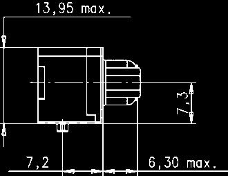
103 D-Sub Number of contacts 9* Standard Versions SMT stamped solder pins, angled with grounding board locks Identification Drawing Dimensions in mm Male connector M3 or 4-40 UNC fitted screw locks M3 or 4-40 UNC Mating face acc. to: CECC M3 or 4-40 UNC fitted screw locks M3 or 4-40 UNC Female connector Mating face acc. to: CECC M3 or 4-40 UNC fitted screw locks M3 or 4-40 UNC pcb layout Packaging (1 reel = 140 pieces) Reel diameter = 330 mm Last 11 pieces without connector 140 pieces with connector First 10 pieces without connector 103
104 D-Sub Number of contacts 9* Low-Profile Versions SMT stamped solder pins, angled with grounding board locks No. of Identification contacts Part No. Performance levels Explanations see page 101 Other performance levels on request Male connector metal shell with dimples Performance level 3 Performance level 2 Performance level Female connector metal shell Please insert digit for flange thread or fitted female screw locks M UNC 16 fitted screw locks M3 18 fitted screw locks 4-40 UNC 17 * 15 and 25 way connectors are available on request Connector dimensions see page 105. Mating conditions see page 101.


 Reel diameter = 330")


105 D-Sub Number of contacts 9* Low-Profile Versions SMT stamped solder pins, angled with grounding board locks Identification Drawing Dimensions in mm Male connector M3 or 4-40 UNC fitted screw locks M3 or 4-40 UNC Mating face acc. to: CECC M3 or 4-40 UNC fitted screw locks M3 or 4-40 UNC Female connector Mating face acc. to: CECC M3 or 4-40 UNC fitted screw locks M3 or 4-40 UNC pcb layout Both holes Packaging (1 reel = 160 pieces) Reel diameter = 330 mm Last 11 pieces without connector 160 pieces with connector First 10 pieces without connector 105
106 D-Sub filter adapters Technical characteristics Number of contacts 9, 15, 25, 37 Working current 6.5 A max. Working voltage Dielectric withstanding voltage 100 V max. for standard capacitance values higher working voltages are available as specific. 250 V DC max. higher dielectric withstanding voltages are available as specific. Contact resistance Insulation resistance 10 m 1000 M Temperature range -20 O C O C Materials Insulation Contacts Contact surface Contact zone Performance level Metal shell PCT, glass-fibre filled, flame retardant acc. to UL 94-V0 Copper alloy Male and female contacts are turned Selectively plated according to performance level Performance level 2, as per CECC , 250 mating cycles, 4 days 4 mixed gas test IEC Steel 106


107 D-Sub Number of contacts Filter adapters No. of Identification contacts Part No. Male / female filter adapters with C filter Please insert digit for capacitance 47 pf pf pf pf 40 Dimensions A B (14.5) 4-40 UNC Male 4-40 UNC (28.3) (16.5) Label Screws are not pre-mounted to allow mounting from any ends 4-40 UNC Female Dimensions in mm 107
, AWG 28/7-30/7, AWG 30 solid Solder pins for ø 0.6 mm min.")
108 Technical characteristics Number of contacts 10 Approvals IEC UL recognized: E Contact pitch Connector pitch 2 mm 6 mm Working current 1.5 A at 70 O C Test voltage U r.m.s. 750 V Contact resistance Insulation resistance 30 m Temperature range during reflow soldering -55 O C O C female: max O C for 60 s Mating cycles 250, performance level 2 Terminations Insulation displacement (male), AWG 28/7-30/7, AWG 30 solid Solder pins for ø 0.6 mm min. (female) Insertion force Withdrawal force 10 N max. / module 2 N min. / module (without locking levers) Latching system Locking levers Materials Mouldings Contacts Shells Contact surface Contact zone Male connector: Polyester, UL 94-V0 Female connector: High temperature plastic material, UL 94-V0 Copper alloy Male connector: Stainless steel Female connector: Silver nickel Selectively gold-plated 108
 27 21 121 8000 10 Red 27 21 121 8002 10 Yellow 27 21 121")
 for pin z 0.4 x (0.3) for pins a, b, c, d, e Identification Part No. Standard cable assembly with single shielding and 1:1 wiring Length: L = 0.5 m L = 1.")

109 Male connectors, straight Female connectors, angled Cable assemblies No. of Identification contacts Colour Part No. Male connector for insulation displacement 10 Black Female connector with solder pins 10 Beige (standard) Red Yellow Green Blue Black Male connector First mate - last break pin (2c) Female connector date code Shielding pins Nipple location Shielding pins 0.4 x (0.25) for pin z 0.4 x (0.3) for pins a, b, c, d, e Identification Part No. Standard cable assembly with single shielding and 1:1 wiring Length: L = 0.5 m L = 1.0 m L = 2.0 m First mate pin har link male IDC connector 5Px28 / 7 AWG braid + foil High end cable assembly with double shielding and 1:1 wiring suitable for HF applications Length: L = 0.5 m L = 1.0 m L = 2.0 m First mate pin har link male IDC connector 5x2x30 / 7 AWG screened pairs braid + foil Dimensions [mm] 109
110 110 Notes
111 SEK Press-in standard version Technical characteristics Number of contacts 10, 14, 16, 20, 26, 34, 40, 50, 60, 64 Contact arrangement straight Terminations Tin-lead plated PCB Recommended PCB through holes Hole 1.15 ±0.025 Cu min. 25 µm Sn max. 15 µm Plated hole mm Contact length 4.5 mm Approvals IEC Design acc. to D 2632 BT 224 BS 9525 NFC (HE 10) MIL DTL Pitch 2.54 mm [0.100 ] Chemical tin-plated PCB Au / Ni plated PCB Hole 1.15 ±0.025 Cu min. 25 µm Sn min. 0.8 µm Plated hole mm Hole 1.15 ±0.025 Cu min. 25 µm Ni 3-7 µm Au µm Plated hole mm Silver plated PCB Hole 1.15 ±0.025 Cu min. 25 µm Ag µm Plated hole mm Working current 1 A OSP copper plated PCB Hole 1.15 ±0.025 Cu min. 25 µm Plated hole mm Working voltage 350 V DC or AC peak PCB board thickness: 1.6 mm Test voltage U r.m.s. 1 kv Contact resistance Insulation resistance 20 m 10 9 Temperature range -55 O C O C The maximum temperature includes heating of contacts and ambient temperature Materials Moulding Contacts Contact surface Contact zone PBT UL 94-V0 Phosphor bronze gold-plated according to performance level 1) Insertion and withdrawal forces Maximum force [N] Number of contacts Performance level ) Performance level 1 as per IEC , 500 mating cycles, 10 days gas test 111
112 SEK IEC Number of contacts Male header, straight press-in pins No. of Part No. Identification contacts Without levers With short levers With long levers Male header with straight press-in terminations Length: 4.5 mm For dimensions see page 113 Performance level 1 as per IEC , other performance levels on request


113 SEK IEC Number of contacts Male header, straight press-in pins Identification Drawing Dimensions in mm Male header No. of contacts A C D E F G x 4 = x 6 = x 7 = x 9 = x 12 = x 16 = x 19 = x 24 = x 29 = x 31 = Marking No. 1 contact Short levers Long levers 2 holes Ø Section B-B 2 holes Ø Board drillings No. 1 contact 1) No polarization slot for 10 or 14 way male header 2) Pitch tolerance: ±


114 SEK Cable connectors pcb 2 rows Technical characteristics Number of contacts 6, 8, 10, 14, 16, 20, 24, 26, 30, 34, 40, 50, 60, 64 Pitch On pcb side: 2.54 mm [0.100 ] On cable side: 1.27 mm [0.050 ] Working current 1 A Test voltage U r.m.s. 1 kv AC 1 minute Contact resistance Insulation resistance 35 m max Temperature range -55 O C O C The maximum temperature includes heating of contacts and ambient temperature Terminations Solder pins: mm x 0.3 mm Dimensions for pcb hole: Standard version: Ø 0.9 ±0.10 mm Kinked version: Ø 1.0 ±0.05 mm Diagonal: 0.71 mm IDC flat cable 1.27 mm [0.050 ] pitch: AWG 28/7 Materials Moulding Thermoplastic resin (PBT) UL 94-V0 114


115 SEK Number of contacts Pcb transition connector, 2 rows, low-profile with 5.5 mm height No. of Identification contacts Part No. Drawing Dimensions in mm Pcb transition connector 2 rows Standard low-profile version No. of contacts A ±0,38 B ±0, x 2 = x 3 = x 4 = x 6 = x 7 = x 9 = x 11 = x 12 = x 14 = x 16 = x 19 = x 24 = x 29 = x 31 = Pcb transition connector 2 rows Kinked low-profile version 2 kinked pins at each extremity Lead No. 1 Lead No. 2 Kinked pins pre-assembled preassembled Standard version assembled Kinked version assembled Board drillings Lead No. 2 Ø 0.90 ±0.10 standard version Ø 1.00 ±0.05 kinked version 1) Pitch tolerance: ± 0.05 Lead No
116 SEK Cable connectors female Technical characteristics Number of contacts 6, 10, 14, 16, 20, 26, 30*, 34, 40, 50, 60, 64 Approvals IEC DIN EN D 2632 BT 224 NFC (HE 10) Current carrying capacity The current carrying capacity is limited by maximum temperature of materials for inserts and contacts including terminals. The current capacity-curve is valid for continuous, not interrupted current-loaded contacts of connectors when simultaneous power on all contacts is given, without exceeding the maximum temperature. Control and test procedures according to DIN IEC UL recognized: E comply with MIL DTL Pitch 2.54 mm [0.100 ] Working current 1 A Working current [A] Working voltage Test voltage U r.m.s. 320 V for pollution degree 1 1 kv Ambient temperature [ C] Example: 50 way connector Temperature rise Derating Derating curve at I max. x 0.8 (IEC ) Contact resistance Insulation resistance Temperature range 20 m O C O C The maximum temperature includes heating of contacts and ambient temperature Terminations IDC flat cable 1.27 mm [0.050 ] pitch: AWG 26/7 AWG 28/7 Insertion and withdrawal forces Maximum force [N] Number of contacts Performance level 1 and 2 Performance level Materials Moulding Contact surface Contact zone Thermoplastic resin (PBTP) UL 94-V0 gold-plated according to performance level 1) 116 1) Performance level 3 as per IEC , 50 mating cycles, no gas test * on request Performance level 2 as per IEC , 250 mating cycles, 4 days gas test as per MIL DTL , > 0.76 µm Au (30 µ inch), other performance levels on request
117 SEK IEC Number of contacts Female connector No. of Identification contacts Part No. Drawing Dimensions in mm Female connector with central polarization without strain relief clamp open end cover closed end cover No. 1 contact No. 2 contact open end cover option closed end cover without strain relief clamp with bulk packaging 2) Packaging unit 5,000 pieces 3) Packaging unit 3,000 pieces U 2) U 2) U 2) U 2) U 2) U 2) U 3) U 3) Marking No. 1 contact Strain relief clamp option with strain relief clamp * * * * * * * * * * * No. of contacts A B No. of contacts A B contacts on request 117 For performance level 3 please specify digit For performance level 2 please specify digit > 0.76 µm Au (30 µinch) on request 7 7 * * 5 * 1) Pitch tolerance: ± 0.1 * Not normally kept in stock

 Packaging unit 5,000 pieces 4) Packaging unit 3,000 pieces 6 09 18 506 9002 58U 3) 6 10 09 18 510 9002 58U 3) 10 14 09 18 514 9002 58U 3) 14 16 09 18 516 9002 58U 3) 16 20 09")
 Strain relief clamp Female connector Low-profile male")
118 SEK IEC Number of contacts Strain relief clamp/locking lever No. of Identification contacts Part No. Drawing Dimensions in mm Strain relief clamp No. of contacts A with bulk packaging 3) Packaging unit 5,000 pieces 4) Packaging unit 3,000 pieces U 3) U 3) U 3) U 3) U 3) U 3) U 4) U 4) contacts on request Locking lever for female connector Only in conjunction with low-profile male header and strain relief ) Strain relief clamp Female connector Low-profile male header Coding system with loss of contact Code pin ) When the security of latching is required and space is a premium, these locking levers can be fitted onto the strain relief of the HARTING female connector. This can then be used in conjunction with male low-profile headers. To avoid cross-plugging adjacent connectors a coding system is required. A code pin is inserted into the appropriate cavity in the female connector. The corresponding male contact is removed by a special removal tool. 118 Removal tool for male contacts 1) Order 2 per female connector 2) Part No. comprises 6 code pins
119 SEK Solder board connectors Technical characteristics Number of contacts 6, 10, 14, 16, 20, 26, 30*, 34, 40, 50, 60, 64 Contact arrangement Contact length straight 2.9 mm Current carrying capacity The current carrying capacity is limited by maximum temperature of materials for inserts and contacts including terminals. The current capacity-curve is valid for continuous, not interrupted current-loaded contacts of connectors when simultaneous power on all contacts is given, without exceeding the maximum temperature. Control and test procedures according to DIN IEC Approvals IEC DIN EN D 2632 BT 224 NFC (HE 10) UL recognized: E comply with MIL DTL Pitch 2.54 mm [0.100 ] Working current [A] Working current Working voltage 1 A 500 V for pollution degree 1 Ambient temperature [ C] Example: 50 way connector Temperature rise Derating Derating curve at I max. x 0.8 (IEC ) Test voltage U r.m.s. Contact resistance Insulation resistance Temperature range 1 kv 20 m O C O C The maximum temperature includes heating of contacts and ambient temperature Terminations For pcb hole Ø 1 ± 0.1 mm DIN IEC Diagonal: 0.79 mm Insertion and withdrawal forces Maximum force [N] Number of contacts Performance level 1 and 2 Performance level Materials Moulding Contact surface Contact zone Thermoplastic resin (PBTP) UL 94-V0 gold-plated according to performance level 1) 1) Performance level 3 as per IEC , 50 mating cycles, no gas test * on request Performance level 2 as per IEC , 250 mating cycles, 4 days gas test as per MIL DTL , > 0.76 µm Au (30 µ inch), other performance levels on request 119
120 SEK IEC Number of contacts Male header with straight solder pins, kinked No. of Part No. Identification contacts Without levers With short levers With long levers Male header with straight solder pins, kinked Length: 2.9 mm contacts on request * Not normally kept in stock For dimensions see page 121 For performance level 3 please specify digit For performance level 2 please specify digit > 0.76 µm Au (30 µinch) on request 7 * * 5 * 5 *


121 SEK IEC Number of contacts Male header with straight solder pins, kinked Identification Drawing Dimensions in mm Male header No. of contacts A C D E F G x 2 = x 4 = x 6 = x 7 = x 9 = x 12 = x 16 = x 19 = x 24 = x 29 = x 31 = Short levers for use with female connector without strain relief clamp No. 1 contact Long levers for use with female connector with strain relief clamp No. 2 contact Marking No. 1 contact No. 1 contact Board drillings No. 2 contact l Kinked contact: pcb thickness from 1.50 to 1.94 mm after Cu + Sn plating with non-remelted through holes ø 0.80 to ø 0.95 mm. Max. insertion force = 125 N. Min. retention force = 6 N. Non-kinked contact: Solder pins for pcb connections ø 1 ± 0.1 mm as per IEC ) No polarization slot for 6, 10 or 14 way male header 2) No polarization slot for 6 way male header 3) Pitch tolerance: ±


 targets the requirements of the next generation of carrier grade telecommunications equipment.")
122 General information 122 PICMG, formally known as the PCI Industrial Computing Manufacturing Group is an industry consortium of over 450 companies. PICMG s standard architectures in an effort to reduce system costs and development cycles and since its 1994 foundation, PICMG has been responsible for the establishment of several of successfully implemented, open, industrial standards. Open standards have proven themselves to be very advantageous for system manufacturers and enduser, because they create multiple vendors of similar parts, low prices at high volumes, and a shortened time-to-market. Historically, PICMG has created several successful standards. PICMG 1.x Series a passive backplane PCI PICMG 2.x Series the CompactPCI standard Today, the AdvancedTCA (PICMG 3.x) targets the requirements of the next generation of carrier grade telecommunications equipment. AdvancedTCA, short for Advanced Telecom Computing Architecture and sometimes simply abbreviated ATCA, incorporates an impressive suite of recent technological advancements including the latest trends in high speed interconnect technologies. Features of AdvancedTCA include optimization for high-capacity, high-performance telecom and industrial applications, improved reliability, manageability, redundability, and serviceability. Encompassing a technological growth path valid for up to ten years, AdvancedTCA has earned a solid position within the telecom systems market. The rack or chassis, is responsible for housing the backplane and the daughtercards, as well as cooling AdvancedTCA chassis with backplane and powering the system. HARTING offers the ATCA power connector that energises the blades, both the straight backplane and the right angled daughtercard connector. The backplane, said to be passive, is merely a medium for the daughtercards to communicate with each other. And, the daughtercards, sometimes called blades or boards, provide the system with its functionality and allow for an easy, hot-swappable module exchange from the front of the system. functionality, and they had to be replaced once their functionality became obsolete or the demands of the system changed. With the continuation of exponential technological growth, concept proved to be a costly endeavour for the end-user. To extend the functionality and modularity of AdvancedTCA, blade manufacturers conceived the idea of upgradeable daughtercards, and began to insert mezzanine cards onto the blades when needed. To achieve a common mezzanine concept, PICMG developed the Advanced Mezzanine Card (AdvancedMC ) standard AMC.0. AdvancedMC modules for different applications For the use of Advanced Mezzanine Cards, as well called AdvancedMC modules, a carrier is necessary. A carrier is an ATCA blade with only little functionality beyond AdvancedMC management. It contains the mechanical environment for the AdvancedMC modules. Depending on their size, up to eight AdvancedMC modules can be hotswapped in and out of a carrier, this enabled the creation of extremely scalable and upgradeable systems.
, current market developments focus on type B+.")
.")

123 General information AdvancedTCA carrier board with AdvancedMC modules To connect AdvancedMC modules to carrier connector: the AdvancedMC connector a card edge connector mounted on the carrier board. It contacts directly with the module s PCB gold pads. connector types (B, B+, AB and A+B+), current market developments focus on type B+. The HARTING AdvancedMC B+ connector features a new design element that supplements the standard increases the mating reliability and prevents contact interruptions and surface wear when subjected to shocks or vibrations. termination technologies. The connector design press-in process control, HARTING offers a special top and bottom tool (see page 140). The HARTING AdvancedMC Plug Connector can replace the module s PCB gold pads and increase the more information about the HARTING AdvancedMC Plug Connector on page 135. MicroTCA double cube system Naturally the mating face of the AdvancedMC connector for MicroTCA is the same as for ATCA, but with a right angled mating direction. It contains the new GuideSpring and is available in press-in termination. PICMG members voted HARTING s MicroTCA connector footprint as the termination technology. AdvancedMC and power connectors for MicroTCA The MicroTCA backplane is typically powered by Power Supply Units (PSU). The PSU connects to the backplane through a MicroTCA power connector This revolutionary AdvancedMC -based design concept has led to the recent development of a completely mezzanine-based system MicroTCA. MicroTCA, short for Micro Telecom Computing than AdvancedTCA when dealing with smaller applications, yet powerful enough to address the needs of telecom, enterprise and medical applications. This newly-implemented PICMG standard, outlined concept whereby AdvancedMC s the same kind used in ATCA systems plug directly into a passive backplane; this eliminates the need for carrier boards. MicroTCA backplane The module management is performed by a MicroTCA Carrier Hub, or MCH. An MCH is connected to the backplane by up to four adjacent card-edge connectors. One MCH can control up to 12 AdvancedMC modules, thus depending on redundancy requirements, workload, or both, one or two MCHs may be used within a single system. For a precise mechnical alignment of the mating tongues HARTING offers the special Plug Connectors according to MTCA.0. (see page 138). 123


124 con:card+ What is con:card+? con:card+ is a quality seal for AdvancedMC connectors that increase in the reliability of MicroTCA TM and AdvancedTCA systems. In order to reach the target availability of %, all system components must be carefully coordinated, and they must function reliably. The selection of suitable connectors is an essential, decisive factor here, as today it is virtually impossible for series production to meet the strict tolerances for the AdvancedMC TM the con:card+ on the internet at Special contact material order to ensure a permanently reliable contact, this single contact tongue must press against contact material for the con:card+ PdNi contact coating 124 In order better to meet the high requirements placed on the connectors, a palladium-nickel As a result, wear resistance is increased by PdNi surfaces offer a quality and corrosionresistant coating that meets the high requirements placed on the connection far


125 Smooth contact surface copper can only stand up to this high load if the This is the case with the con:card+ GuideSpring tight tolerances with certainty in the series tolerances slightly larger than allowed by The con:card+ pressing the module against the opposite towards the middle, the slot is optimally and the mating reliability increases module position in the case of shocks and corrosion-resistant, low-ohm quality mechanical connection between the pin and the through substantiate that the required transmission rates 125
126 AdvancedMC connectors for AdvancedTCA Technical characteristics Design according PICMG AMC.0 (RoHS compliance) Number of contacts 170 Contact spacing 0.75 mm Clearance and creepage distance between contacts 0.1 mm min. Working current of C power contacts max. 30 C temp. rise as defined in AMC.0 spec. Test voltage 80 V r.m.s. Initial contact resistance ground contacts 60 m max. signal, power, general purpose contacts 90 m max. Initial insulation resistance 100 M min. Nominal differential impedance 100 ±10 % Max. 25 ps risetime Bottom route Adjacent 0.55 % Basic-to-extended (diagonal) 0.68 % Basic-to-extended (opposite) 0.39 % Multiline (five multi-aggressor differential pairs) 2.74 % max extended side basic side ground PCB library on request (PADS/Dx-Designer) SPICE models and S-Parameter on request Differential propagation delay Basic side: 125 ps Extended side: 145 ps Differential skew Between basic and extended side: 20 ps Within basic and extended side: ±2 ps Materials Moulded parts Contacts Contact surface Packaging Liquid Crystal Polymer (LCP), UL 94-V0 Copper Alloy Palladium nickel plated Cardboard box (other packaging on request) Recommended plated through hole specification Hole Ø 0.64 ±0.01 mm Tin plated PCB (HAL) Cu µm Sn 5 15 µm Plated hole Ø mm Hole Ø 0.64 ±0.01 mm Cu µm Au / Ni plated PCB Ni 3 7 µm Au µm Plated hole Ø mm Hole Ø 0.64 ±0.01 mm Chemical tin plated PCB Cu µm Sn µm Plated hole Ø mm Hole Ø 0.64 ±0.01 mm Silver plated PCB Cu µm Ag µm Plated hole Ø mm Hole Ø 0.64 ±0.01 mm OSP copper plated PCB Cu µm Plated hole Ø mm The press-in zone of the AdvancedMC connector is tested according to Telcordia/Bellcore GR 1217CORE Part7. It is approved to be used with a plated through hole according IEC with a diameter of 0.55 ±0.05 mm (drilled hole 0.64 ±0.01 mm). Based on our experiences regarding the production process of the PCB manufacturer we recommend a plated through hole configuration like shown in the above spreadsheet. To achieve the recommended plated through hole diameter, it is important to specify especially the drilled hole diameter of 0.64 ±0.01 mm to your PCB supplier. For drillings use e.g. drill bit # 72 (0.025" Hole Ø 126 Temperature range -55 C +105 C Durability as per AMC.0 specification 200 mating cycles Termination technique Mating force Withdrawal force Press-in termination 100 N max. 65 N max. Plated hole Ø Cu e.g. Sn
![AdvancedMC connectors for AdvancedTCA Card edge connectors, angled Contact length [mm] No.](/docs-images/92/108187468/images/127-2.jpg "of termination Identification contacts side Part number AdvancedMC connector for ATCA, type B+ with peg and with GuideSpring 170 2.")
127 AdvancedMC connectors for AdvancedTCA Card edge connectors, angled Contact length [mm] No. of termination Identification contacts side Part number AdvancedMC connector for ATCA, type B+ with peg and with GuideSpring AdvancedMC connector for ATCA, type B+ without peg and with GuideSpring With peg Without peg With peg Without peg 1) fixing-hole optional 2) non-metallized drillings 3) recommended plated through hole specification see page 126 Board drillings (view magnified) all holes keep out area for press in bottom tool row for ground Dimensions [mm] 127

128 Power connectors for AdvancedTCA Technical characteristics Design according PICMG 3.0 R2.0 Total number of contacts 30, max. 34 Power contacts 8 Signal contacts 22, max. 26 Clearance and creepage distance between contacts Within group mm min. Within group mm min. 25 to mm min. Within group mm min to mm min to mm min to mm min. Sequential contact engagement 1st 25, 26, 28, 29, 30, 31 2nd 33 3rd 5 24, 34 4th 27, 32 Working current Power contacts Signal contacts Test voltage Contacts 1 16 Contacts Initial contact resistance Power contacts Signal contacts Insulation resistance 16 A 1 A 1000 V r.m.s V r.m.s. 2.2 m 8.5 m Temperature range -55 C +125 C Durability 250 mating cycles Termination technique Mating force Withdrawal force Press-in termination 67 N max. 67 N max. Materials Moulded parts Contacts Contact surface Packaging PBT, glass-fibre filled, UL 94-V0 Copper Alloy Selectively gold plated Tray packaging (other packaging on request) Recommended plated through hole specification Tin plated PCB (HAL) Au / Ni plated PCB Chemical tin plated PCB Silver plated PCB OSP copper plated PCB Signal contacts Power contacts Hole Ø 1.15 ±0.025 mm 1.75 ±0.025 mm Cu µm µm Sn 5 15 µm 5 15 µm Plated hole Ø mm mm Hole Ø 1.15 ±0.025 mm 1.75 ±0.025 mm Cu µm µm Ni 3 7 µm 3 7 µm Au µm µm Plated hole Ø mm mm Hole Ø 1.15 ±0.025 mm 1.75 ±0.025 mm Cu µm µm Sn µm µm Plated hole Ø mm mm Hole Ø 1.15 ±0.025 mm 1.75 ±0.025 mm Cu µm µm Ag µm µm Plated hole Ø mm mm Hole Ø 1.15 ±0.025 mm 1.75 ±0.025 mm Cu µm µm Plated hole Ø mm mm The press-in zone of the AdvancedTCA power connector is tested according to Telcordia/Bellcore GR 1217CORE Part7. It is approved to be used with a plated through hole according IEC with a diameter of mm for signal contacts and mm for power contacts (drilled hole 1.15 ±0.025 mm resp ±0.025 mm). Based on our experiences regarding the production process of the PCB manufacturer we recommend a plated through hole configuration like shown in the above spreadsheet. To achieve the recommended plated through hole diameter, it is important to specify especially the drilled hole diameter of 1.15 ±0.025 mm resp ±0.025 mm to your PCB supplier. Derating for ATCA power contacts Contact loading acc. PICMG 3.0 Current [A] Hole Ø Cu 128 À Derating Á I max. x 0.8 (acc. IEC ) Ambient temperature [ C] Plated hole Ø e.g. Sn
![Power connectors for AdvancedTCA Contact length [mm]](/docs-images/92/108187468/images/129-0.jpg "No. of termination Identification contacts side Part")


129 Power connectors for AdvancedTCA Contact length [mm] No. of termination Identification contacts side Part number Power connector for AdvancedTCA, male Power connector for AdvancedTCA, female Male connector with 30 contacts Female connector with 30 contacts Board drillings view X Signal contacts Dimension A position , Power contacts Dimension B position view X position position position 1) + 2) recommended plated through hole specification see page 128 Dimensions [mm] 129
130 AdvancedMC connector for MicroTCA Technical characteristics Design according PICMG MTCA.0 R1.0 (RoHS compliance) Number of contacts 170 Contact spacing 0.75 mm Clearance and creepage distance between contacts 0.1 mm min. Materials Moulded parts Contacts Contact surface Packaging Liquid Crystal Polymer (LCP), UL 94-V0 Copper Alloy Palladium nickel plated Cardboard box (other packaging on request) Working current of C power contacts max. 30 C temp. rise as defined in MTCA.0 spec. Test voltage 80 V r.m.s. Initial contact resistance 25 m max. Initial insulation resistance 100 M min. Nominal differential impedance 100 ±10 % Max. 25 ps risetime Bottom route Adjacent 0.58 % Basic-to-extended (diagonal) 0.30 % Basic-to-extended (opposite) 0.38 % Multiline (five multi-aggressor differential pairs) 1.91 % max extended side ground basic side PCB library on request (PADS/Dx-Designer) SPICE models and S-Parameter on request Differential propagation delay Basic side: 75 ps Extended side: 75 ps Differential skew Between basic and extended side: ±2 ps Within basic and extended side: ±2 ps Recommended plated through hole specification Hole Ø 0.64 ±0.01 mm Tin plated PCB (HAL) Cu µm Sn 5 15 µm Plated hole Ø mm Hole Ø 0.64 ±0.01 mm Cu µm Au / Ni plated PCB Ni 3 7 µm Au µm Plated hole Ø mm Hole Ø 0.64 ±0.01 mm Chemical tin plated PCB Cu µm Sn µm Plated hole Ø mm Hole Ø 0.64 ±0.01 mm Silver plated PCB Cu µm Ag µm Plated hole Ø mm Hole Ø 0.64 ±0.01 mm OSP copper plated PCB Cu µm Plated hole Ø mm The press-in zone of the AdvancedMC connector is tested according to Telcordia/Bellcore GR 1217CORE Part7. It is approved to be used with a plated through hole according IEC with a diameter of 0.55 ±0.05 mm (drilled hole 0.64 ±0.01 mm). Based on our experiences regarding the production process of the PCB manufacturer we recommend a plated through hole configuration like shown in the above spreadsheet. To achieve the recommended plated through hole diameter, it is important to specify especially the drilled hole diameter of 0.64 ±0.01 mm to your PCB supplier. For drillings use e.g. drill bit # 72 (0.025" Hole Ø 130 Temperature range -55 C +105 C Durability as per MTCA.0 spec. 200 mating cycles Termination technique Mating force Withdrawal force Press-in termination 100 N max. 65 N max. Plated hole Ø Cu e.g. Sn
![AdvancedMC connector for MicroTCA Card edge connector, straight Contact length [mm] No.](/docs-images/92/108187468/images/131-0.jpg "of termination Identification contacts side Part number AdvancedMC connector for MicroTCA with")
 recommended plated through hole specification see page 130 2)")

131 AdvancedMC connector for MicroTCA Card edge connector, straight Contact length [mm] No. of termination Identification contacts side Part number AdvancedMC connector for MicroTCA with GuideSpring ) recommended plated through hole specification see page 130 2) fixing-hole optional non-metallized drillings 3) optional: use fillister-head tapping screws 2.2 x length, shape C, acc. to ISO 7049 (length = PCB thickness + min. 4 mm) Board drillings (view magnified) all holes Lc of card slot row for ground housing contour Dimensions [mm] 131
 Total number of contacts 96 Power contacts 24 Signal contacts 72 Sequential contact engagement 1st Power 4 11 2nd Power 1 3, power 12 24 3rd Signal A2 H9 4th Signal A1 Working")
132 Power output connectors for MicroTCA Technical characteristics Design according PICMG MTCA.0 R1.0 (RoHS compliance) Total number of contacts 96 Power contacts 24 Signal contacts 72 Sequential contact engagement 1st Power nd Power 1 3, power rd Signal A2 H9 4th Signal A1 Working current Power contacts Signal contacts Initial contact resistance Power contacts 5 m Signal contacts 25 m Temperature range -55 C +105 C Durability 200 mating cycles Termination technique Mating force Withdrawal force % derating acc. IEC and 70 C ambient temperature and 30 C temperature rise 1 80 % derating acc. IEC and 70 C ambient temperature Initial insulation resistance 100 M min. Press-in termination 145 N max. 110 N max. Derating for MicroTCA power contacts Contact loading acc. MTCA.0 Materials Moulded parts Contacts Contact surface Power contacts: Signal contacts: Packaging PBT, glass-fibre filled, UL 94-V0 Copper Alloy selectively gold plated selectively palladium nickel plated Tray packaging (other packaging on request) Recommended plated through hole specification Hole Ø 0.7 ±0.02 mm Tin plated PCB (HAL) Cu µm Sn 5 15 µm Plated hole Ø mm Hole Ø 0.7 ±0.02 mm Cu µm Au / Ni plated PCB Ni 3 7 µm Au µm Plated hole Ø mm Hole Ø 0.7 ±0.02 mm Chemical tin plated PCB Cu µm Sn µm Plated hole Ø mm Hole Ø 0.7 ±0.02 mm Silver plated PCB Cu µm Ag µm Plated hole Ø mm Hole Ø 0.7 ±0.02 mm OSP copper plated PCB Cu µm Plated hole Ø mm PCB board thickness: The press-in zone of the MicroTCA power connector is tested according to Telcordia/Bellcore GR 1217CORE Part7. It is approved to be used with a plated through hole according IEC with a diameter of mm (drilled hole 0.70 ±0.02 mm). Based on our experiences regarding the production process of the PCB manufacturer we recommend a plated through hole configuration like shown in the above spreadsheet. To achieve the recommended plated through hole diameter, it is important to specify especially the drilled hole diameter of 0.70 ±0.02 mm to your PCB supplier. Hole Ø Current [A] Cu 132 À Derating Á I max. x 0.8 (acc. IEC ) Ambient temperature [ C] Plated hole Ø e.g. Sn


133 Power output connectors for MicroTCA Contact length [mm] No. of termination Identification contacts side Part number Power output connectors for MicroTCA module version backplane version Module version Backplane version view X Board drillings position row all holes row position position all holes position row all holes row all holes 1) recommended plated through hole specification see page 132 Dimensions [mm] 133

. Compact-Size 3 HP 15.24 mm Mid-Size 4 HP 20.32 mm Full-Size 6 HP 30.48 mm MCH 1.5 HP 7.")
 could unintentional mate with connectors of the adjacent slot or could be plugged into the wrong slot.")


 need to be designed into the backplane or the sub rack mechanics.")
134 Protection Block for MicroTCA backplanes Identification Part number MicroTCA Protection Block The MicroTCA specification defines modules with the option of multiple mating interfaces like the MCH module for system management and switching. There are four different pitches defined for the module interfaces and the backplane connectors respectively, the basic unit is called horizontal pitch (HP) and is 5.08 mm (0.2 inch). Compact-Size 3 HP mm Mid-Size 4 HP mm Full-Size 6 HP mm MCH 1.5 HP 7.62 mm Any MCH (or other multiple mating interface modules) with more than two mating interfaces (2x MCH-pitch 1.5 HP = Compact-Size pitch 3 HP) could unintentional mate with connectors of the adjacent slot or could be plugged into the wrong slot. Even though the pinassignment and e-keying for the MCH is defined, it can cause system failures or even destroy hardware if a MCH is inserted into two adjacent AMC Compact-Size slots. For other multiple mating interface modules, this situation is even worse, because neither e-keying nor pin assignment is specified in MTCA.0. To prevent errors in case of misinsertion, MTCA.0 R1.0 chapter 2.13 outlines protection blocks that occupy the space between two adjacent connectors in a Compact-Size slot. Furthermore this protection block can be used for keying functions of multiple mating interface modules. HARTING designed a protection block fully independent of the backplane and sub rack design. The HARTING protection block is clipped between two connectors, hence no fixing features (holes, clips...) need to be designed into the backplane or the sub rack mechanics. The assembly is done quick and easy by hand. It can The free space between the backplane connectors is occupied by the protection block even be installed easily after the backplane is mounted with a simple flat-head screwdriver, an easy removal is possible in a similar way. The keying block can be placed into four different positions, hence a keying of multitongue modules by using tongues with a cutout is possible. 134 MicroTCA backplane with protection blocks


135 General information As already explained in the chapter con:card+, it is very difficult for a PCB manufacturer to produce the tight tolerances of the AdvancedMC module card edge in a consistent process. Furthermore the quality of the card edge gold pads is not well defined in detail by the specification. With the introduction of the con:card+ connectors, HARTING supports the reliable operation of AdvancedMC by the different con:card+ features. But some disadvantages of a card edge connection can only be eliminated by a mating half connector. HARTING AdvancedMC Plug The most important advantages of the HARTING AdvancedMC Plug Connector are the low module insertion forces and enhanced contact surfaces resulting in higher mating cycles with much tighter two piece connector tolerances. The AdvancedMC Plug Connector replaces the gold pads of the module card edge. The AdvancedMC module with a Plug Connector is still within the module envelope of the PICMG AMC.0 specification and is fully mating compatible with AdvancedMC card edge connectors. Consequently the Plug Connector can be used in both MicroTCA and ATCA environments. The PICMG standard AMC.0 defines hard gold for the card edge interface. But a common and unique definition of hard gold does not exist today. As a result the quality of the gold pads in terms of hardness and roughness is highly unsteady. Additionally, the gaps between the pre and functional pad (which are necessary for the hot-swap ability) require a selective hard gold process which is more complicated than a standard process. This can lead to exposed copper and sharp pad edges. The contacts of the HARTING AdvancedMC Plug Connector are plated all-around and are manufactured in a defined band plating process with controlled quality. There are different performance levels possible as the noble finish thickness can be easily adapted to customer demands. By using a HARTING AdvancedMC Plug Connector, the mating interface of the module is defined by the connector instead of the PCB. This fact leads to decisive advantages and provides a wide scope for the module development. For the module card egde, the prepads of lagging contacts are required by the Telcordia/Bellcore specification to avoid wearing of the connector contact when sliding on the FR4 base material. The Plug Connector does not need prepads. The four mating steps are realized as real lagging contacts. The sophisticated design of the insulator reduces the mating forces of the module significantly. The card edge chamfer is important to reduce mating forces and to avoid wearing and damage of the backplane connector. But also the PCB milling process of the chamfer is critical. In contrast to the PCB the Plug Connector has a moulded chamfer with a smooth surface protecting the backplane connector contacts. As the Plug Connector defines the mating tongue, the restriction of the PCB thickness of 1.6 mm ±10% does not need to be considered anymore. The maximum PCB thickness is only limited by the card guide for the AMC modules. The Plug Connector itself has a thickness of 1.5 ±0.04 mm to reduce the mating force. The width of the Plug Connector is near the maximum width of the specification to support high mating reliability when the module is plugged into a connector without the GuideSpring con:card+ feature. The connector is mounted to the PCB with the pinin-hole-reflow solder technology (PIHR) and is pickand-place compatible. Another advantages of this efficient and mechanically stable technology, is that the connector can be replaced. This can avoid the scrapping cost of a module if the mating interface is damaged during handling. AdvancedMC module with a HARTING AdvancedMC Plug Connector Depending on the application, the additional cost of the connector can be compensated by several savings during the production process of the AdvancedMC module. Please contact our local sales office for further information about the advantages of the HARTING AdvancedMC Plug Connector. 135
136 Technical characteristics for Plug Connectors Design according PICMG MicroTCA.0 R1.0 PICMG AMC.0 R2.0 (RoHS compliance) Number of contacts 170 Materials Moulded parts Contacts Liquid Crystal Polymer (LCP), UL 94-V0 Copper alloy Contact spacing 0.75 mm Contact surface Au over Ni Clearance and creepage distance between contacts 0.1 mm min. Packaging Tray packaging (other packaging on request) Working current min C max. 30 C temp. rise acc. to pin configuration in AMC.0 spec. Working current tested with HARTING MicroTCA backplane connector 2 A min. Test voltage 80 V r.m.s. Initial contact resistance Initial insulation resistance 25 m max. 100 M min. Nominal differential impedance 100 ±10 % Plated through hole recommendations A Plated hole-ø mm 0.02 B Hole-Ø 0.65 ±0.01 mm C Remaining pad 0.95 mm Temperature range -55 C +105 C during reflow soldering 220 C for 2 minutes 270 C max. short-term Durability as per AMC.0 specification Termination technique Pick-and-place-weight Mating force Withdrawal force 200 mating cycles in total Solder termination (Pin in Hole Intrusive Reflow) < 7 g 100 N max. 65 N max. Stencil recommendation 136 The mating and withdrawal force is highly depending on the mating half connector, but typically only 50 % to 70 % of the mating force of a PCB card edge. Each termination requires a solder paste volume of 0.57 mm³. Since the stencil can only provide fractions of this volume (0.29 mm³ at 0.15 mm stencil thickness), the remaining solder paste must be pressed into the plated through hole. For a nominal AMC card (1.6 mm PCB thickness, 0.55 mm plated hole diameter) the paste must penetrate the hole by 0.7 mm.


 Non-metallized")
137 AdvancedMC Plug Connector for MicroTCA and AdvancedTCA No. of Identification contacts Part number AdvancedMC Plug Connector AdvancedMC Plug Connector with nozzle pad for pick and place assembly AdvancedMC Plug Connector Board drillings 1) Plated holes, plating recommendations see page 136 2) Non-metallized drillings Dimensions [mm] 137


138 General information One important component of a MicroTCA system is the so called MicroTCA Carrier Hub, abbreviated MCH. The main functions of an MCH module are the hardware platform management and the management of the fabric connectivity. As the MCH module needs many more connections than a standard AdvancedMC module, an MCH can have up to 4 mating tongues each with 170 contacts. To build a connector stack for two, three or four mating tongues, the HARTING Plug Connectors are mounted like building blocks via pegs and holes of the adjacent Plugs. For additional mechanical stability, the connector stack is fixed by up to four metal stacking pins. The complete connector stack can be easily installed without any special tooling by only handling three different parts (AdvancedMC Plug Connector, MCH Plug Connector and the corresponding stacking pins). stacking pins AdvancedMC Plug MCH Plug MCH Plug The MTCA.0 specification recommends the use of a special Plug Connector to reduce the insertion force of the module and to solve the tolerance stack-up problem between the multiple tongues and the backplane connectors. The HARTING Plug Connector system consists of a configuration with two different Plug Connectors. The AdvancedMC Plug Connector is mated with the backplane MCH connector. MCH connector 1 is needed for the base function of the system. Furthermore it can be used for any conventional AdvancedMC module to replace the PCB gold pads. The MCH Plug Connector is mated with the backplane MCH connectors 2, 3, 4 depending on the MicroTCA configuration. Compared to the AdvancedMC Plug, the MCH Plug insulator has standoffs securing the right distance for the slot width between two tongues or backplane connectors respectively. The MCH and AdvancedMC Plugs have different contact staggering on the basic side, the extended side is equal. For a MicroTCA system with more than 6 AdvancedMC modules using the switched fabric fat pipe, an MCH module MCH Plug with 4 mating tongues has to be used. Depending on the application, the switched fabric is located only on the third board, so a high speed connection is needed between the mating tongue 4 and the PCB 3. For this purpose, HARTING offers a special high speed adapter. The MCH Flex Adapter offers high speed characteristics with mechanical flexibility. HARTING delivers the complete assembly consisting of one MCH Plug and a mezzanine connector soldered to a flexible PCB. The mating half of the mezzanine connector can be delivered by HARTING also. 138 MCH modules can have up to 4 mating tongues. HARTING offers two versions of the Plug and a special Flex Adapter.


 1) Plated holes, plating")
139 Plug Connectors for MCH modules No. of Identification contacts Part number AdvancedMC Plug Connector AdvancedMC Plug Connector with nozzle pad for pick and place assembly MCH Plug Connector MCH Plug Connector with nozzle pad for pick and place assembly AdvancedMC MCH Plug stacking-pin double, length mm triple, length mm quad, length mm MCH Flex Adapter AdvancedMC Plug Connector MCH Plug Connector Board drillings (view magnified) 1) Plated holes, plating recommendations see page 136 2) Non-metallized drillings alle Löcher Dimensions [mm] 139
140 Press-in tooling For a reliable and safe press-in process HARTING has developed a special tooling system. Each tooling is adapted to the special requirements of the individual connector range, thus a good handling and quick adjustment is guaranteed. The different demands of the system designs will be covered from the highly adaptable tooling system for AdvancedTCA or MicroTCA with the following options: Guiding of the connector and alignment of the top and the bottom tool Guiding of the PCB and alignment of the top and the bottom tool Pins for guiding the connector PCB Example for different options to guide connector or PCB. Pins for guiding the PCB Identification Part No. Drawing Top tool for AdvancedTCA B+ Bottom tool for AdvancedTCA B Top tool for AdvancedTCA B+ Bottom tool for AdvancedTCA B+ Top tool for MicroTCA Bottom tool for MicroTCA Top tool for MicroTCA Bottom tool for MicroTCA Top tool for AdvancedTCA Power Male and female connector Bottom tool for AdvancedTCA Power Male and female connector Top tool for AdvancedTCA Power and MicroTCA Power, module version Bottom tool for AdvancedTCA Power Top tool for MicroTCA Power Module version Backplane version Bottom tool for MicroTCA Power Module version Backplane version Top tool for MicroTCA Power, backplane version Bottom tool for MicroTCA Power, module version Bottom tool for MicroTCA Power, backplane version 140 Removal tool for AdvancedTCA B+ Removal tool for MicroTCA Repair pliers for MicroTCA Removal tool for AdvancedTCA B+ Removal tool for MicroTCA Repair pliers for MicroTCA


 Guide frame with base plate Standard")

141 Press-in tooling Identification Part No. Drawing Dimensions in mm Hand bench press Technical characteristics Working stroke 25 mm Press force 15 kn max. Hole ø in the ram ø 10 mm Net weight approx. 23 kg Pneumatic press 40 kn Technical characteristics Total stroke 48 mm Working stroke 0-6 mm Press force 40 kn max. Air pressure 6 bar Hole ø in the ram ø 10 mm Net weight 136 kg Power supply 110 V / 220 V AC CPM prestige Technical characteristics Drive electromechanical, servo Press-in force 100 kn max. PCB dimensions 600 x 1000 mm Floor space 1200 x 1150 mm Weight 980 kg Power supply 208 / 380 / 400 / 415 V Consumption < 1 kw Colour on request Adaptor for height compensation 1) Guide frame with base plate Standard type for PCB size x = 123,5-309,5 mm Long type 2) for PCB size x = 123,5-668,5 mm Base plate ) suitable for and all CPM machines 2) not suitable for hand bench press base plate 141


142 Signal integrity support Introduction HARTING offers signal integrity support to the end customers. We provide simulation models and evaluation kits with our products for signal integrity investigations. The evaluation kits are assembled with SMA s to connect them directly with the measurement instruments. The benefit is that the customer saves time and costs for pre-evaluation of the connector. We offer test boards suitable for the connector evaluation itself and have built reference backplanes and test cards for measurements within applications like VME, CompactPCI, AdvancedTCA and MicroTCA. Reference structures and well established measurement techniques allow a full de-embedding of the propagation characteristics of the interconnect itself for test and verification. Furthermore we developed several high-speed test backplane with different connector areas and PCB design topologies. We can provide footprint and routing recommendations for our products. A variety of testboards, simulation models and further technical data for different products are available on request. HARTING is also an active member in standardization groups like VITA, PICMG, OBSAI and supports sub-committees for new interconnect solutions. We are in close cooperation with customers, universities and industrial partners for research activities. Signal integrity capabilities Simulation and modeling Measurement and verification Test fixture & reference backplane design Design-in support Simulation and modeling Capability to perform full 3D-FEM simulations of the CAD-geometry with different well established tools like CST Microwave Studio and Ansoft HFSS. Post-processing of the data for field-distribution and full S-parameter and time-domain analysis within the software packages themselves and additional Matlab tools. 142 For SPICE-modeling, impedance calculation and field distribution analysis of the geometry S-parameter models are used in combination with static 3D-FEM, 2D-FEM and planar field solvers depending on the desired bandwidth of the signal. These models are used as library parts for channel simulations including particular chip, trace, vias and connector subcircuits. Eye-diagram, S-parameter and waveform analysis of the entire channel are performed with tools like HSPICE and ADS (Advanced Design System).


 Insertion- and return loss,")


143 Signal integrity support Measurement and verification Time-domain measurements Parameters: Characteristic impedance Propagation delay Rise time degradation Reflection Crosstalk Eye-diagram and mask-test Bit-error rate testing (BERT) up to 12.5 Gbps per differential line Frequency-domain measurements Parameters: 4 port S-parameter analysis (up to 40 GHz) Insertion- and return loss, crosstalk, VSWR Fourier-transformation, gating, error-location PLTS software to calculated time-domain data, eye-diagrams, etc. Test fixture & reference backplane design Design-in support Customized PCB design close to the real application Footprint and routing recommendations Full measurement characterization and test report Simulation models 143


144 Catalogue order information Please send me further information: CD-Rom HARKIS basic DVD HARKIS basic Interface Connectors Telecom Outdoor Solutions Industrial Connectors Han Connectors DIN Ethernet Network Solutions Automation IT Coaxial and Metric Connectors Application brochure Sender: Company: TCA Connectors Device Connectivity DeviceCon Street: Backplanes and Integrated Systems Department: Name: Prename: Function: representatives (see page addresses) or visit us Postcode/Town: Country: Phone: Fax:


 20 764 61 Fax +358 (0) 20 764 6820 E-Mail:")


145 Production plants worldwide Representatives worldwide Argentina Condelectric S.A. Hipólito Yrigoyen 2591 (B1640HFY) Martínez, Buenos Aires Phone + Fax info@condelectric.com.ar Estonia HARTING Electric SKS Tehnika OÜ, Liimi 1 EE Tallinn Tel , Fax tehnika@sks.fi Internet: Espelkamp / Germany Plant 1 Espelkamp / Germany Plant 2 Espelkamp / Germany Plant 3 Canada HARTING Electric Chartwell Electronics Inc. 140 Duffield Drive Markham, Ontario L6G 1B5 Phone Toll Free Fax Internet: Denmark Knud Wexøe A/S Skaettekaeret 11, P.O. Box 152 DK-2840 Holte Phone Fax wexoe@wexoe.dk Internet: Zhuhai / China Finland HARTING Electric SKS Automaatio Oy Martinkyläntie 50, FI Vantaa Phone +358 (0) Fax +358 (0) automaatio@sks.fi Internet: Finland HARTING Electronics INTOTEL OY Kutojantie 4, Espoo, Finland P.O. Box 125, Espoo, Finland Phone Fax into@intotel.fi Internet: Island HARTING Electric Smith & Norland, Nóatún 4 IS 105 Reykjavík Phone Fax olaf@sminor.is Internet: Israel HARTING Electric MIGVAN Technologies & Eengineering Ltd. 13 Hashiloh St., P.O.Box 7022 IL Petach Tikva Phone Fax info@mte.co.il Internet: Espelkamp / Germany Plant 4 Northampton / Great Britain Biel / Switzerland Espelkamp / Germany Plant 5 Sibiu / Romania Elgin / USA
HARTING. News People Power Partnership
 98 42 914 0201 HARTING News 2008 People Power Partnership Quality Connections Worldwide HARTING was founded in 1945 by the family that still owns the company. Its headquarters are situated in Espelkamp,
Han-Brid. Contents Han-Brid Features Han-Brid Data interfaces Han-Brid Overview Han-Brid Cu
 Contents Page Features... 19.02 Data interfaces... 19.03 Overview... 19.04 Cu... 19.06 F.O.... 19.08 Quintax 3 A... 19.10 RJ45 C... 19.12 USB / FireWire... 19.14 Han 4 A SC... 19.16 Hoods/Housings... 19.18
HARTING News 2007
 98 42 914 0201 HARTING News 2007 People Power Partnership Quality Connections Worldwide HARTING was founded in 1945 by the family that still owns the company. Its headquarters are situated in Espelkamp,
HARTING econ 3000 Introduction and features
 Introduction and features HARTING econ 3000 es, unmanaged, for installation in control cabinets General Description Features The Fast es of the product family HARTING econ 3000 are suitable for industrial
Ethernet cabling. B Ethernet cabling. Ethernet cabling overview B 2. Cabling 4-poles IP 20 B.1 8 IP 65 / IP 67 B Cables B Tools B.
 Ethernet cabling Contents Page B Ethernet cabling Ethernet cabling overview B 2 Cabling 4-poles B.1 8 B.1 22 Cables B.1 96 Tools B.1 104 Cabling 8-poles B.2 8 B.2 20 Cables B.2 90 Tools B.2 98 B 1 Profile
Han PCB termination. Han-Fast Lock PCB adapter for Han DD PCB adapter for Han DDD module
 Han termination Contents Page Han-Fast Lock... 20.11 adapter for Han DD... 20.13 adapter for Han DDD module... 20.16 adapter for Han 40 A Axial module... 20.18 adapter for Han E... 20.20 adapter for Han
HARTING scon Introduction and features
 HARTING scon Introduction and features Introduction For the user, HARTING s novel and innovative solutions open up new, more convenient and exten- Switches. The solutions available to date offered only
HARTING. Interface Connectors. People Power Partnership
 11 5 HARTING Interface Connectors People Power Partnership Directory chapter 00 Modular metric high speed connectors, 2.0 mm pitch Page connector system general information......................... 00.04
02. PushPull CONNECTORS
 . CONNECTORS A distributed automation system does not contain any central automated control cabinets. Controls, sensors and actuators are designed for a high degree of protection (IP 65 / IP 67) and are
HARTING. Ethernet Network Solutions Automation IT
 19 3 HARTING Ethernet Network Solutions Automation IT HARTING WORLDWIDE Introduction Transforming customer wishes into concrete solutions 00 Headquartered in Espelkamp in East Westphalia, Germany, the
02. PushPull CONNECTORS
 . CONNECTORS A distributed automation system does not contain any central automated control cabinets. Controls, sensors and actuators are designed for a high degree of protection (IP 65 / IP 67) and are
M12 connector D-coding M12 connector X-coding RJ45 IP20 connector PushPull RJ45 IP65 / IP67 connector
 M12 connectors Directory Chapter Page General information....02 M12 connector D-coding....06 M12 connector X-coding....20 RJ45 IP20 connector....27 PushPull RJ45 IP65 / IP67 connector....46 Han 3 A RJ45
HARTING Device Connectivity PushPull
 HARTING Device Connectivity PushPull People Power Partnership O v e r v i e w Device Connectivity: Solutions from HARTING For device manufacturers, Harting offers a comprehensive product line of device
harting Smart Network Infrastructure Selection Guide
 harting Smart Network Infrastructure Selection Guide Selection guide In just a few steps to a complete network With this selection guide you get an easy tool, which supports you in designing your Automation
Technical characteristics A Technical characteristics F.O. termination A Ha-VIS mcon 3100-AV A Ha-VIS mcon 3100-AAV A.
 Ha-VIS mcon Contents Page Management Software Overview A.4 3 Management functions A.4 9 mcon 3000 Introduction and features A.4 11 Technical characteristics A.4 12 Technical characteristics F.O. termination
Ha-VIS mcon 3000 Next Generation Introduction and features
 Ha-VIS Next Generation Introduction and features Ha-VIS Next Generation es, managed, for mounting onto top-hat mounting rail in control cabinets General Description Features The fully Managed es of the
07. har-link INTERFACE CONNECTORS
 . INTERFACE CONNECTORS The highest data rates in combination with perfect shielding characterize the connector. This way data can be passed on optimally within the control cabinet. The locking mechanism
Ha-VIS econ 2000 Fast and Full Gigabit Ethernet Basic. Features
 2000 Fast and Full Gigabit Ethernet Basic Commercial Temp.: / Industrial Temp.: Power Sourcing Equipment (PSE) with 4 Ports PoE+ (34.2 watts per port) General description Unmanaged Ethernet switches of
Transforming customer wishes into concrete solutions
 HARTING News 2013 HARTING worldwide Introduction Transforming customer wishes into concrete solutions The HARTING Technology Group is skilled in the fields of electrical, electronic and optical connection,
07. har-link Interface Connectors
 . Interface Connectors The highest data rates in combination with perfect shielding characterize the connector. This way data can be passed on optimally within the control cabinet. The locking mechanism
HARTING. News People Power Partnership
 98 42 914 0201 HARTING News 2011 People Power Partnership H A R T I N G w o r l d w i d e Transforming customer wishes into concrete solutions 2 The HARTING Technology Group is skilled in the fields of
Applications
 Han PCB adapter Contents Page Technical characteristics PCB adapter for Han DD... 20.02 Han DD Inserts with PCB adapter... 20.03 Technical characteristics PCB adapter for Han E... 20.04 Han E Inserts with
HARTING Connectors for High Mating Cycles
 HARTING Connectors for High Mating Cycles HARTING worldwide Transforming customer wishes into concrete solutions The HARTING Technology Group is skilled in the fields of electrical, electronic and optical
Han R 23. Circular Connector. Certified acc. to DIN EN ISO 9001 in design/ development, production, installation and servicing.
 Circular Connector Certified acc to DIN EN ISO 9001 in design/ development, production, installation and servicing Data Sheet 0039-4 Circular Connectors Features Size R 23 Outer diameter 26 mm High contact
HARTING Ha-VIS mcon 3000 Next Generation Full managed Ethernet PROFINET Switch
 HARTING Ha-VIS mcon 3000 Next Generation Full managed Ethernet PROFINET Switch Datenblatt / Datasheet Zubehör / Accessoires 1 Ha-VIS mcon 3000 Next Generation Introduction and features Ha-VIS mcon 3000
07. har-link Interface Connectors
 . Interface Connectors The highest data rates in combination with perfect shielding characterize the connector. This way data can be passed on optimally within the control cabinet. The locking mechanism
Standard Hoods/Housings Han B Size 16 B
 Standard / Han B Size 16 B Metal hoods/housings for industrial applications / 2 lever locking system 09 30 016 1520 1 x 21 09 30 016 0520 1 x 21 09 30 016 0521 1 x 29 angled entry 09 30 016 0663 2 x 21
Better all-round. DataVoice Circular connectors STX M12x1 IP67 Connector series for industrial applications. PoE+ 10 GBE. coded.
 Better all-round. X coded D coded 10 GBE PoE+ DataVoice Circular connectors STX M12x1 IP67 Connector series for industrial applications STX M12x1 IP67 connector series With the STX M12x1 IP67 connector
Industrial Ethernet Panel-Mount Adaptors for PROFINET or EtherNet/IP Applications
 Industrial Ethernet Panel-Mount Adaptors for PROFINET or EtherNet/IP Applications Type 0981 ENC 100 RJ45/M12 adaptor, female receptacle connector M12, D coding, chassis side thread PG 9, RJ45 female connector,
FL MC 2000T. Fiber optic converter for 10/100Base-Tx to single- or multi-mode fiberglass with SC-duplex and ST connections. Data sheet 3379_en_B
 Fiber optic converter for 10/100Base-Tx to single- or multi-mode fiberglass with SC-duplex and ST connections Data sheet 3379_en_B 1 Description PHOENIX CONTACT 2015-07-14 2 Features Media converters provide
PROFIBUS Repeater PRC P PROFIBUS Converter PCF PF P PROFIBUS Converter PCF PF P20.05
 Contents chapter age General information............................... 00 Repeater.......................................... 10 Repeater RC 67-10............................... 10.01 Converter.........................................
revos revos Industrial Multipole Connectors
 revos revos Industrial Multipole Connectors Catalog 2018 revos MINI Plant II, Rodezstraße in Bamberg Company headquarters in Bamberg STOCKO main plant in Wuppertal Solutions for Building technology AT
Details of the Han-Terminal block connector Han D AV Han D AV Distributor Han E AV Han ES AV
 Contents -Terminal Block Connectors Page Details of the -Terminal block connector........................ 08.02 D................................................... 08.10 D Distributor...........................................
6000 Series Buccaneer. 30 twist locking Tamperproof lock prevents accidental un-mating. Cat 5e shielded coupler Maintains shielding
 circular connectors that combine the ease of use of a push/pull coupling mechanism with proven environmental sealing. Available with metal or plastic bodies, the range supports both data (USB and Ethernet),
HARTING Rugged Indoor/Outdoor Light & Sound connections
 HARTING Rugged Indoor/Outdoor Light & Sound connections People Power Partnership HARTING WORLDWIDE Transforming customer wishes into concrete solutions The HARTING Technology Group is skilled in the fields
Transforming customer wishes into concrete solutions
 HARTING News 2016 HARTING worldwide Transforming customer wishes into concrete solutions 2 The HARTING Technology Group is skilled in the fields of electrical, electronic and optical connection, transmission
Description of parts Panel mounting Insert mounting without/with Carrier element Plastic housings
 - Contents Page Features -... 11.02 Component range -... 11.03 Description of parts... 11.04 Latching parts without/with Strain relief and Panel mounting parts... 11.06 Panel mounting... 11.08 Insert mounting
INDUSTRIAL ETHERNET SWITCHES WAGO Solutions at the Heart of the Industrial ETHERNET
 INDUSTRIAL ETHERNET SWITCHES WAGO Solutions at the Heart of the Industrial ETHERNET 1 Contents ETHERNET Switches ECO and Standard 3 4 SFP Modules Interface for Fiber-Optic 5 ETHERNET Switches Managed 6
FL MC 2000E (SM40) LC
 LC") IEC 61850 fiber optic converter with LC fiber optic connection (1310 nm) to convert 100Base-Tx to single- or multi-mode fiber glass Data sheet 3205_en_C 1 Description PHOENIX CONTACT 2014-04-04 2 Features
IEC 61850 fiber optic converter with LC fiber optic connection (1310 nm) to convert 100Base-Tx to single- or multi-mode fiber glass Data sheet 3205_en_C 1 Description PHOENIX CONTACT 2014-04-04 2 Features
Operating voltages up to 40 kvdc Operating current up to 30 Amps Advanced contact technology Silver plated and gold plated contacts available High
 Operating voltages up to 40 kvdc Operating current up to 30 Amps Advanced contact technology Silver plated and contacts available High performance insulation material General characteristics and technical
FL MC 10/100BASE-T/FO-660
 Extract from the online catalog FL MC 10/100BASE-T/FO-660 Order No.: 2708193 FO converter, for converting 10/100Base-T to polymer and HCS fiber, (660 nm), SCRJ FO connection (PROFINET standard), rail-mountable,
Industrial Switches Industrial Switches
 Industrial Switches Industrial Switches Copper cables Fiber optic cable Ring redundancy Industrial Switches Contents 23 General Product Information 2 Interfaces and Configurations 2 Application and Installation
Modular Connectors 75
 75 Plug/Jack Compliant to Enhanced Category 5 standards Connector type Size Series Name Page plug connectors compliant to enhanced category 5 standards 8 TM21P 77 jack connectors for high-speed LAN transmission
09. DIN Connectors
 . Connectors Connectors that comply with have been in use for years for both board-to-board applications and cable-to-board applications. Their robustness and universality are legendary. The classic signal
8-port 10/100TX + 2-Port 10/100/1000T/100/1000 SFP Combo with 8 PoE Injectors Industrial Ethernet Switch User Manual
 8-port 10/100TX + 2-Port 10/100/1000T/100/1000 SFP Combo with 8 PoE Injectors Industrial Ethernet Switch User Manual FCC Warning This Equipment has been tested and found to comply with the limits for a
Device Server for the conversion of serial interfaces (RS-232/422/485) to IP.
 to IP.") Manual Entry Line Industrial Gigabit Ethernet Switch 4x 10/100/1000Base-T, 1x SFP Ports MICROSENS General The IP protocol has already left the in-house environment and is going to take all remaining communication
Manual Entry Line Industrial Gigabit Ethernet Switch 4x 10/100/1000Base-T, 1x SFP Ports MICROSENS General The IP protocol has already left the in-house environment and is going to take all remaining communication
4 10/100/1000T Mini-GBIC with 4 IEEE 802.3at High Power PoE Industrial Wide Temperature Switch. User Manual SISTP LRT
 4 10/100/1000T + 2 1000 Mini-GBIC with 4 IEEE 802.3at High Power PoE Industrial Wide Temperature Switch User Manual V1.0 September-2013 FCC Warning This Equipment has been tested and found to comply with
04 4E HARTING. Solutions for Industrial Ethernet
 04 4E HARTING Solutions for Industrial Ethernet People Power Partnership Quality Connections Worldwide HARTING was founded in 1945 by the family that still owns the company. Today, HARTING employs around
Type Qty. Order No. IE-PI-HYB-10P
 IP67 plug-in connector Hybrid plug inserts Cat.5 IP 20 For Variant 1, 4 and 14 housings Crimp Passive components C Category Degree of protection Plugging cycles Shielding Housing main material Wire cross-section,
Modular Connector System with High Power, Signal, Fibre-Optic, Coaxial Contacts and Pneumatic Valves
 Modular Connector System with High Power, Signal, Fibre-Optic, Coaxial Contacts and Pneumatic Valves 2 rue René Laennec 51500 Taissy France Fax: 03 26 85 19 08, Tel : 03 26 82 49 29 E-mail:hvssystem@hvssystem.com
Extract from new. Device Connectivity catalogue. HARTING har-flex. People Power Partnership
 Extract from new Device Connectivity catalogue HARTING har-flex People Power Partnership . har-flex CONNECTORS The continuous scalability by an even number of contacts, i.e. from 6 to 100, of the HARTING
Technical data: Pin Spacing
 282 Female Connectors, Double-Row Pin Spacing: 3.5 mm Universal connection for all conductor types Unique, compact, double-row connector system for conductor cross sections up to 1.5 mm 2 High-density,
09. DIN CONNECTORS
 . 41 612 CONNECTORS Connectors that comply with 41 612 have been in use for years for both board-to-board applications and cable-to-board applications. Their robustness and universality are legendary.
General. 5 and 8 port Fast Ethernet switches. 6 and 8 Port Gigabit Ethernet switches. Switches with fiber uplink
 Entry Line Industrial Gigabit Ethernet Switch 4x 10/100/1000Base-T with PoE+, 1x 10/100/1000Base-T or 100/1000Base-X Combo Port, 1x 100/1000Base X SFP Slot General The IP protocol has already left the
modlink msdd Front panel interfaces
 Tight and with full visibility The connecting mechanism of the Modlink MSDD with integrated locking mechanism allows the components to be used under protection class IP65. This protection class prevents
6000 Series Buccaneer
 Robust, instant connections for harsh environments 6000 Series Buccaneer - circular connectors that combine the ease of use of a push/pull coupling mechanism with proven environmental sealing. Available
10/100/1000T to Mini-GBIC Industrial Switch Converter 10/100/1000T to 1000SX/LX Industrial Switch Converter. AMG9011G-H (-40 to 75C) User Manual
 User Manual") 10/100/1000T to Mini-GBIC Industrial Switch Converter 10/100/1000T to 1000SX/LX Industrial Switch Converter AMG9011G-H (-40 to 75C) User Manual www.amgsystems.com Content Overview...1 Introduction... 1
10/100/1000T to Mini-GBIC Industrial Switch Converter 10/100/1000T to 1000SX/LX Industrial Switch Converter AMG9011G-H (-40 to 75C) User Manual www.amgsystems.com Content Overview...1 Introduction... 1
LNP-0602 series. 6-port Industrial PoE+ Unmanaged Ethernet Switches 4*10/100Tx (30W/Port) + 2*100Fx. User Manual
 + 2*100Fx. User Manual") LNP-0602 series 6-port Industrial PoE+ Unmanaged Ethernet Switches 4*10/100Tx (30W/Port) + 2*100Fx User Manual FCC Warning This Equipment has been tested and found to comply with the limits for a Class-A
LNP-0602 series 6-port Industrial PoE+ Unmanaged Ethernet Switches 4*10/100Tx (30W/Port) + 2*100Fx User Manual FCC Warning This Equipment has been tested and found to comply with the limits for a Class-A
ODU MINI-SNAP PC Product Description. ODU MINI-SNAP PC: The Connector with Push-Pull-Locking in Plastic
 ODU MINI-SNAP PC Product Description ODU MINI-SNAP PC: The Connector with Push-Pull-Locking in Plastic Cylindrical Connectors are generally available with several locking mechanisms: The most frequently
EPIC Circular Connectors CIRCON M23 Series
 The M3 connectors have many inherent features which offer application advantages and provide significant benefits for the customer. These features make it one of the most application friendly connectors
Summary of shell housings and accessories Shell housing A Shell housing D EMC housing
 Directory chapter 20 Page Summary of shell and accessories........................... 20.02 housing C.......................... 20.04 housing A................................................. 20.08 housing
FISCHER MINIMAX TM SERIES
 TECHNICAL SPECIFICATIONS FISCHER TM SERIES Fischer Connectors SA All rights reserved Web version 1.0-03.2016 Changes without prior notice FISCHER TM SERIES KEY FEATURES The Fischer MiniMax Series increases
D-Sub SEaled subminiature D connectors, 2.54 mm pitch
 SE D-Sub SEaled subminiature D connectors, 2.54 mm pitch Page Technical characteristics.......................................... 02 IP 67 versions with turned solder cups......... 04 IP 67 versions with
Data sheet... OMNIMATE Power - series BL/SL 7.62HP BLZ 7.62HP/04/180LR SN BK BX
 Power on board #96 100% safety, 100% integration, 100% cost-effectiveness: The compact and efficient solution for UL-600V applications in the lower performance range (up to 12 kva). 29 A at 400V (IEC)
HARTING Han-Power Power Networks and Industrial Cabling
 HARTING Han-Power Power Networks and Industrial Cabling 400 V People Power Power Partnership Partnership 24 V 1 04 08 10 12 * MCU 14 PRODUKTFAMILIE 16 18 LEISTUNGSKLASSE PRODUKTNAME STECKVERBINDER INSTA
M12 Field Wireable Connectors. M12 CAT.6A Field Wireable Connectors. M12 Field Wireable Connectors for PROFINET
 M12 Connectors Application Advantage Shielded design ETHERLINE Ethernet Cable, Connectors & Tools M12 Field Wireable Connectors Male Female Temperature Range: Max. 85 C Nominal Voltage: Nominal Current:
CONEC Industrial Ethernet Circular Sealed RJ45 Connector System consists of a RJ45 Plug Kit, a Receptacle Kit and a Protective Cover Assembly.
 Revised Sept-28-2009 Sealed Industrial Ethernet Circular IP67 Cat. 5e RJ45 Connector System Instructions CONEC Industrial Ethernet Circular Sealed RJ45 Connector System consists of a RJ45 Plug Kit, a Kit
M23 Connectors and cables
 Contents Product Description: SAI M23 Connectors.2 Contact assignment.7 Technical data.8 Overview.10 M23 connector for signal transmission.12 M23 connector for power transmission.18 Moulded M23 cables.22
Innovative system solutions flexible connection technology
 426 Innovative system solutions flexible connection technology Systems for direct Ethernet device connection 1 Direct PC Board Connection 433 2 IP67 Protected Connectors Variant 1 436 3 IP67 Protected
IP68 Sealed - Mini USB Buccaneer
 IP68 Sealed - IP68 Over moulded assembly provides IP68 cable seal Coupling ring, screw thread provides secure cable coupling Mini USB connector O ring maintains IP68 seal at connector interface Mini USB
NEW. Phone: Fax: Web: -
 NEW 8-port unmanaged switch in IP67 Just 54 mm wide One LED per port for link / speed / data Fault relay: 1 x M12 A-coded, 5-pole (24 V DC / 1 A) 8 x M12 D-coded, 4-pole Redundant voltage supply 2 x M12
M12x1 Circular Connectors
 M12x1 Circular Connectors Agenda 1. Introduction M12x1 Circular Connectors 2. M12x1 X-coded 3. M12x1 D-coded 4. Accessories and Nomenclature 3 / 2015 Product Presentation M12x1 Page 2 M12x1 Circular Connectors
1 10/100TX FX w/ 1 PoE Injector Industrial Switch. User Manual
 1 10/100TX + 1 100FX w/ 1 PoE Injector Industrial Switch User Manual CE Mark Warning This is a Class-A product. In a domestic environment this product may cause radio interference in which case the user
Multipole Industrial Connectors Heavy duty connectors
 Multipole Industrial Connectors Heavy duty connectors Compact catalogue For more technical details, specifications ions and special products please consult the Westec General Catalogue Multipole Industrial
VMEbus systems System description Technical characteristics System description
 Directory chapter 06 / inverse Page VMEbus systems................................................ 06.02 System description.............................................. 06.03 Technical characteristics..........................................
LNP series. 5-port Industrial PoE+ Unmanaged Ethernet Switches 4*10/100Tx (30W/Port) + 1*10/100Tx, 12~36VDC Input.
 + 1*10/100Tx, 12~36VDC Input.") LNP-0500-24 series 5-port Industrial PoE+ Unmanaged Ethernet Switches 4*10/100Tx (30W/Port) + 1*10/100Tx, 12~36VDC Input User Manual FCC Warning This Equipment has been tested and found to comply with
LNP-0500-24 series 5-port Industrial PoE+ Unmanaged Ethernet Switches 4*10/100Tx (30W/Port) + 1*10/100Tx, 12~36VDC Input User Manual FCC Warning This Equipment has been tested and found to comply with
10/100TX to 100FX w/ 1 PoE Injector Industrial Media Converter User Manual
 10/100TX to 100FX w/ 1 PoE Injector Industrial Media Converter User Manual v1.02 FCC Warning This Equipment has been tested and found to comply with the limits for a Class-A digital device, pursuant to
gigabit industrial ethernet user manual Models , ,
 gigabit industrial ethernet Switch user manual Models 503495, 503532, 503570 Model shown: 503495 INT-503495/503532/503570-UM-0308-01 introduction Thank you for purchasing this INTELLINET NETWORK SOLUTIONS
EPIC LS1 Series Circular Power & Mixed Power Connectors
 EPIC LS1 Series Circular Power & Mixed Power Connectors EPIC LS1 Circular and Mixed Power Connectors are designed to DIN specification EN61984 and have a standard M23 threaded connection housing. They
IEC-0101FT Industrial 10/100TX to 100M-FX Slim Type Converter User Manual
 Lantech IEC-0101FT Industrial 10/100TX to 100M-FX Slim Type Converter User Manual FCC Warning This Equipment has been tested and found to comply with the limits for a Class A digital device, pursuant to
Industrial 5-Port Fast Ethernet Switches. with SFP Slot and optional 4 PoE PSE Ports. Basic Model: KSD-541. PoE Model: KSD-541-HP. Installation Guide
 Industrial 5-Port Fast Ethernet Switches with SFP Slot and optional 4 PoE PSE Ports Basic Model: KSD-541 PoE Model: KSD-541-HP Installation Guide DOC.141201-1- (C) 2014 KTI Networks Inc. All rights reserved.
Connector System for Fluorescent Lighting Fixtures. Connectors for In-Line Mounting of Fluorescent Lighting Fixtures. Fully Polarized Connectors
 Connector System for Fluorescent Lighting Fixtures Connectors for In-Line Mounting of Fluorescent Lighting Fixtures Fully Polarized Connectors Luminaire Disconnect Connectors Pluggable Lighting Connectors
PowerDRIVE-Box GEL 6505 Interface for controlling up to 5 positioning drives
 PowerDRIVE-Box GEL 6505 Interface for controlling up to 5 positioning drives Technical information Version 208-05 GEL 6505A: Box for top hat rail mounting, IP 20 variant General The PowerDRIVE-Box GEL
Standard Buccaneer - Ethernet
 IP6 rated IP69K, Tested in accordance with DIN 40050/Part 9 IP6k9k or compliant PUR / PVC jacket on cable Shielded system or shielded coupler Shroud on RJ45 Screw coupling Rewireable flex connector PCB
6000 Series Buccaneer
 Robust, instant connections for harsh environments 6000 Series Buccaneer - circular connectors that combine the ease of use of a push/pull coupling mechanism with proven environmental sealing. Available
LNX-0702G-SFP Series
 LNX-0702G-SFP Series 7-Port Industrial Gigabit Unmanaged Ethernet Switches 5*10/100/1000Tx + 2*100/1000 SFP Slots User Manual Version 1.0 i Copyright 2014 Antaira Technologies, LLC All Rights Reserved
Electrical Interconnection
 Electrical Interconnection Edition 208/ Rail-Mount Terminal Block Systems Full Line Catalog, Volume Edition 207/208 PCB Terminal Blocks and Connectors Full Line Catalog, Volume 2 Edition 207/208 2 Automation
Data sheet C6 A modul 90 jack
 Illustrations Dimensional drawing Cut-out Page 1/7 See enlarged drawings at the end of document Product specification modular Cat.6 A termination unit RJ45 mounting version: module, 90 cable feed solid,
PoE Powered 10/100BASE-TX to 100BASE-FX Media Converters. KC-351 Series. Installation Guide
 PoE Powered 10/100BASE-TX to 100BASE-FX Media Converters KC-351 Series Installation Guide -1- DOC.070820-KC-351 (C) 2007 KTI Networks Inc. All rights reserved. No part of this documentation may be reproduced
Absolute Encoders Multiturn
 The multiturn encoders 6 and 8, with interface and combined optical and magnetic sensor technology, offer a maximum resolution of 5 bits. These encoders are programmable via the Ezturn software. The hollow
PROFIBUS Repeater PRC P PROFIBUS Converter PCF PF P PROFIBUS Converter PCF PF P20.05
 Contents chapter age General information............................... 00 Repeater.......................................... 10 Repeater RC 67-10............................... 10.01 Converter.........................................
Lantech. IPES /100TX with 4 PoE Injectors 24~48VDC Industrial Switch. User Manual
 Lantech IPES-0008-4 8 10/100TX with 4 PoE Injectors 24~48VDC Industrial Switch User Manual V1.00 Jun 2010 FCC Warning This Equipment has been tested and found to comply with the limits for a Class-A digital
Standard Buccaneer BUCCANEER FOR POWER
 IP8 rating tested at 1.05kg/sq cm (15lb/sq in) 10m depth for weeks and.8kg/sq cm (10lb/sq in) 100m depth for hours IPK, Tested in accordance with DIN 0050/Part IPkk Water and dustproof to IP8 when mated,,,,,,
User Manual Entry Line Industrial Fast Ethernet Switch 5x 10/100Base-TX
 User Manual Entry Line Industrial Fast Ethernet Switch 5x 10/100Base-TX Entry Line Fast Ethernet Switch Fast Ethernet Switch for Industrial Use Page 2/11 Table of Contents General... 3 Benefits... 3 Front
DESINA installation technology
 DEcentralized Standardized INstAllation technology DESINA describes an extensive concept for the standardization and decentralization of the fluid power and electrical installation of machines and applications.
Manual 2Wire Converter
 Manual 2Wire Converter Ethernet everywhere via any existing pair of wires Adatis GmbH & Co. KG Version 08/2015 Page 1 of 14 Table of contents 1. About this product 3 1.1. Features 3 1.2. Equipment overview
Industrial Switches. Industrial switches. Copper cables Fiber optic cables Ring redundancy
 Industrial Switches Industrial switches Copper cables Fiber optic cables Ring redundancy www.wago.com Volume Section Industrial Switches Industrial Switches Contents Page General Product Information 8
Item No.: /
 mounting adapter also for DIN 35 rail; % protected against mismating; Plate thickness 06x12 mm; Male connector; with snap-in mounting foot; 4-pole; pin spacing 35 mm / 0138 in; with 209-137 mounting adapter
FL SWITCH SFN(T) 16-Port Standard Function Ethernet Switches for Normal and Extreme Environments. AUTOMATION Data Sheet 2806_en_C
 16-Port Standard Function Ethernet Switches for Normal and Extreme Environments. AUTOMATION Data Sheet 2806_en_C") 16-Port Standard Function Ethernet Switches for Normal and Extreme Environments AUTOMATION Data Sheet 2806_en_C 1 Description PHOENIX CONTACT 2011-06-28 2 Features and Benefits The FL SWITCH SFN(T) 16(15)(14)TX
16-Port Standard Function Ethernet Switches for Normal and Extreme Environments AUTOMATION Data Sheet 2806_en_C 1 Description PHOENIX CONTACT 2011-06-28 2 Features and Benefits The FL SWITCH SFN(T) 16(15)(14)TX
1000Base-SX / LX to 10/100/1000Base-T 802.3at PoE Industrial Media Converter
 Base-SX / LX to 10/100/Base-T 802.3at Industrial Media Converter Physical Port PLANET IGTP-80xT Industrial Gigabit Media Converter series combines Ethernet media conversion (from Base-X to 10/100/Base-T)